


TV |
|
|
|
|
|
Service Manual |
|||
Zusätzlich erforderliche Unterlagen für den Komplettservice Additionally required Service Documents for the Complete Service
Service |
NUR |
|
Manual |
||
|
||
Sicherheit |
|
|
Safety |
|
|
Materialnr./Part No. |
|
|
720108000001 |
|
|
|
|
ARGANTO 23
LW 60-6410 TOP
GMK9100
|
|
|
|
|
|
|
|
|
|
|
|
|
|
GEBRAUCH |
||
|
|
|
|
|
|
|
|
|
|
|
|
|
|
|||
|
|
|
|
|
|
|
|
|
|
|
|
|
|
|
|
Y |
|
|
|
|
|
|
|
|
INTERNEN |
|
USE |
ONL |
|||||
|
|
|
|
|
|
|
|
|
|
|||||||
|
|
|
|
|
|
|
|
|
|
|
||||||
FÜR |
INTERNAL |
|
|
|||||||||||||
FOR |
|
|
|
|
|
|
|
|
||||||||
Materialnummer/Part Number 720100485000 Änderungen vorbehalten/Subject to alteration H-S43 0804
http://www.grundig.com
GRUNDIG Service |
ARGANTO 23 LW 60-6410 TOP |
Es gelten die Vorschriften und Sicherheitshinweise gemäß dem Service Manual "Sicherheit", Materialnummer 720108000001, sowie zusätzlich die eventuell abweichenden, landesspezifischen Vorschriften!
The regulations and safety instructions shall be valid as provided by the "Safety" Service Manual, part number 720108000001, as well as the respective national deviations.
Inhaltsverzeichnis
|
Seite |
Allgemeiner Teil ................................... |
1-2…1-6 |
Allgemeine Hinweise .................................................................... |
1-2 |
Technische Daten ........................................................................ |
1-3 |
Mögliche Auflösungen PC-Eingang ............................................. |
1-3 |
Serviceund Sonderfunktionen .................................................... |
1-4 |
Fehlersuchdiagram ...................................................................... |
1-5 |
Platinenabbildungen |
|
und Schaltpläne ................................. |
2-1…2-16 |
Blockschaltplan ............................................................................ |
2-1 |
Netzteil ......................................................................................... |
2-2 |
Hauptplatte ................................................................................... |
2-3 |
– Teil 1 VGA Interface ................................................................. |
2-3 |
– Teil 2 YPrPb Interface .............................................................. |
2-4 |
– Teil 3 Audio Interface ............................................................... |
2-5 |
– Teil 4 Scart Interface ................................................................ |
2-6 |
– Teil 5 MPU Interface ................................................................ |
2-7 |
– Teil 6 Panel Interface ............................................................... |
2-8 |
– Teil 7 Power Interface .............................................................. |
2-9 |
– Teil 8 Videotext ...................................................................... |
2-10 |
– Teil 9 Video Interface ............................................................. |
2-11 |
– Teil 10 Scaler ......................................................................... |
2-12 |
Scart-Platte ................................................................................ |
2-16 |
Tuner-Platte ............................................................................... |
2-17 |
Explosionszeichnung |
|
und Ersatzteilliste ................................ |
3-1…3-2 |
Explosionszeichnung ................................................................... |
3-1 |
Ersatzteilliste ................................................................................ |
3-2 |
Allgemeiner Teil
Allgemeine Hinweise
Vor dem Öffnen des Gehäuses den Netzstecker ziehen! Achtung: ESD-Vorschriften beachten 
Leitungsverlegung
Bevor Sie die Leitungen und insbesondere die Masseleitungen lösen, muss die Leitungsverlegung zu den einzelnen Baugruppen beachtet werden.
Nach erfolgter Reparatur ist es notwendig, die Leitungsführung wieder in den werkseitigen Zustand zu versetzen um evtl. spätere Ausfälle oder Störungen zu vermeiden.
Durchführen von Messungen
Bei Messungen mit dem Oszilloskop an Halbleitern sollten Sie nur
Tastköpfe mit 10:1 - Teiler verwenden. Außerdem ist zu beachten, dass nach vorheriger Messung mit AC-Kopplung der Koppelkondensator des Oszilloskops aufgeladen sein kann. Durch die Entladung
über das Messobjekt können Bauteile beschädigt werden.
Messwerte und Oszillogramme
Bei den in den Schaltplänen und Oszillogrammen angegebenen Messwerten handelt es sich um Näherungswerte!
Table of Contents
|
Page |
General Section .................................... |
1-2…1-8 |
General Notes .............................................................................. |
1-2 |
Technical Data ............................................................................. |
1-3 |
Possible Resolutions of PC Input ................................................. |
1-3 |
Service and Special Funtions ...................................................... |
1-4 |
Fault Finding Diagram .................................................................. |
1-7 |
Layout of PCBs |
|
and Circuit Diagrams ......................... |
2-1…2-16 |
Block Diagram .............................................................................. |
2-1 |
Power Supply ............................................................................... |
2-2 |
Main Board ................................................................................... |
2-3 |
– Part 1 VGA Interface ................................................................ |
2-3 |
– Part 2 YPrPb Interface ............................................................. |
2-4 |
– Part 3 Audio Interface .............................................................. |
2-5 |
– Part 4 Scart Interface ............................................................... |
2-6 |
– Part 5 MPU Interface ................................................................ |
2-7 |
– Part 6 Panel Interface .............................................................. |
2-8 |
– Part 7 Power Interface ............................................................. |
2-9 |
– Part 8 Videotext ...................................................................... |
2-10 |
– Part 9 Video Interface ............................................................ |
2-11 |
– Part 10 Scaler ........................................................................ |
2-12 |
Scart PCB .................................................................................. |
2-16 |
Tuner PCB ................................................................................. |
2-17 |
Exploded View |
|
and Spare Parts List ............................ |
3-1…3-2 |
Exploded View ............................................................................. |
3-1 |
Spare Parts List ........................................................................... |
3-2 |
General Section
General Notes
Before opening the cabinet disconnect the mains plug! Attention: Observe the ESD safety regulations 
Wiring
Before disconnecting any leads and especially the earth connecting leads observe the way they are routed to the individual assemblies. On completion of the repairs the leads must be laid out as originally fitted at the factory to avoid later failures or disturbances.
Carrying out Measurements
When making measurements on semi-conductors with an oscilloscope, ensure that the test probe is set to 10:1 dividing factor. If the previous measurement was made on AC input, please note that the coupling capacitor in the oscilloscope will be charged. Discharge via the item being checked can damage the components.
Measured Values and Oscillograms
The measured values given in the circuit diagrams and oscillograms are approximates!
1 - 2

GRUNDIG Service ARGANTO 23 LW 60-6410 Top
Technische Daten / Technical Data
|
|
ARGANTO 23 |
|
|
LW 60-6410 TOP |
Bild |
|
|
Display |
|
Activ Matrix TFT-LC-Display |
Bildschirmdiagonale / sichtbares Bild |
ca. cm |
58 / 58 |
Bildseitenverhältnis 16:9 (Breitbild-Format) |
|
• |
4 verschiedene Formatumschaltungen |
|
• |
Ansprechzeit |
ca. ms |
25 |
Kontrast-Verhältnis |
ca. |
400 : 1 |
Blickwinkel |
ca. |
170 vertikal, 170 horizontal |
Leuchtdichte des Panels |
ca. cd/m |
450 |
Auflösung max. |
pixel |
WXGA 1280 x 1024 |
Bildschärfeeinstellung / Kammfilter |
|
–/• |
Electronic |
|
|
Intelligentes Bedienkonzept (OSD) |
|
• |
Autom. Senderprogrammierung ATS euro plus |
|
• |
Bild-im-Bild (1-Tuner-PIP) |
|
• |
PIP-Text |
|
• |
On timer / Sleep timer |
|
–/• |
Programm-Speicherplätze TV / AV |
|
99 / 5 |
Videotext / Seiten-Speicher |
|
•/10 |
|
|
BG, I, DK/K’, L/L’. PAL, SECAM |
|
|
über AV: NTSC 4,43 + 3,58 MHz. |
TV-Standard |
|
A2 für B/G/D/K/I, |
|
|
Nicam 5,85 MHz (BG, L) |
|
|
+ 6,52 MHz (I) |
Infrarot-Fernbedienung |
|
• |
Ton |
|
|
Stereo-/Zweikanalton-Empfang |
|
•/• |
Musikleistung / Sinusleistung |
ca. Watt |
2 Kanal 14 / 10 |
Kopfhörer-Lautstärke getrennt regelbar |
|
– |
Kopfhörer-Tonkanalwahl bei Zweikanalton |
|
– |
Lautsprecher |
|
2 Breitband frontal |
Anschlüsse / Buchsen |
|
|
S-Video-Eingang (Hosiden) |
|
• |
Euro-AV-Buchse / davon RGB und S-Video tauglich |
|
1x / 1x |
Wireless-AV-Buchse |
|
– |
Cinch-AV-Buchsen |
|
• |
Kopfhörer-Buchse (Ø 3,5 mm) |
|
• |
YUV-Buchsen (Progressive Scan) |
|
• |
VGA für PC |
|
• (Multisync WUXGA) |
Drahtlose Bildund Tonübertragung nachrüstbar |
|
Modul WT-AV 1 |
Netzteil |
|
|
Spannung (Regelbereich), Frequenz 50/60 Hz |
V~ |
100-240 |
Netzteil integriert |
|
• |
Leistungsaufnahme im TV-Betrieb / Standby |
ca. Watt |
120 / < 15 |
Gewicht |
ca. kg |
10,5 |
Abmessungen ca. (Breite x Höhe x Tiefe) |
ca. cm |
68 x 43 x 9,5 (21 mit Fuß) |
Zubehör (im Lieferumfang) |
|
VGA-Monitor-Kabel |
Technische Angaben ohne Gewähr.
Mögliche Auflösungen PC-Eingang / Possible Resolutions of PC Input
Mode No. |
Mode Name |
Resolution |
H.Freq. (kHz) |
V.Freq. (Hz) |
H. Polarity |
V. Polarity |
Pixel/CLK (MHZ) |
1 |
VGA 70Hz |
640 x 350 |
31,469 |
70,087 |
+ |
- |
25,175 |
2 |
VGA 60Hz |
640 x 480 |
31,469 |
59,469 |
- |
- |
25,175 |
3 |
VGA 72Hz |
640 x 480 |
37,861 |
72,81 |
- |
- |
31,5 |
4 |
VGA 75Hz |
640 x 480 |
37,5 |
75,0 |
- |
- |
31,5 |
5 |
SVGA 56Hz |
800 x 600 |
35,16 |
56,25 |
+ |
+ |
36,0 |
6 |
SVGA 60Hz |
800 x 600 |
37,879 |
60,317 |
+ |
+ |
40,0 |
7 |
SVGA 72Hz |
800 x 600 |
48,077 |
72,188 |
+ |
+ |
50,0 |
8 |
SVGA 75Hz |
800 x 600 |
46,875 |
75,0 |
+ |
+ |
49,5 |
9 |
XGA 60Hz |
1024 x 768 |
48,363 |
60,004 |
- |
- |
65,0 |
10 |
XGA 70Hz |
1024 x 768 |
56,476 |
70,069 |
- |
- |
75,0 |
11 |
XGA 75Hz |
1024 x 768 |
60,023 |
75,029 |
+ |
+ |
78,75 |
12 |
MAC VGA |
640 x 480 |
35,0 |
66,667 |
- |
- |
30,24 |
13 |
MAC VGA |
832 x 624 |
49,550 |
74,550 |
- |
- |
57,283 |
14 |
US Text |
720 x 400 |
31,469 |
70,087 |
- |
+ |
28,322 |
15 |
WXGA 60Hz |
1280 x768 |
47,733 |
60,042 |
- |
- |
80 |
1 - 3
GRUNDIG Service |
ARGANTO 23 LW 60-6410 Top |
Serviceund Sonderfunktionen
Tastenfunktionen
MENU |
- Aufrufen des Service Menü ("Menu Screen") |
|
- Menü-Punkt aktivieren |
P+/P– |
Menü-Zeile (Menüpunkt) wählen |
/ |
Wert ändern |
Service-Mode aktivieren
–Taste "MENU" am Gerät gedrückt halten und Gerät mit der Taste "POWER" auf der Fernbedienung einschalten.
–Service Menü ("Menu Screen") mit Taste "MENU" auf der Fernbedienung aufrufen.
Service-Mode beenden
– Gerät ausschalten.
Software-Versionsnummer
Im Service Menü wird jeweils in der untersten Zeile die Versionsnummer angezeigt.
Service and Special Funktions
Functions of the buttons
MENU |
- Call up the Service Menu ("Menu Screen") |
|
- Activate menu point. |
P+/P– |
Call up te dialogue line (point of menu) |
/ |
Changing the settings |
Calling up the Service Mode
–Hold button "MENU" at the set depressed while switching on the set with button "POWER" on the remote control.
–Activate the Service Menu ("Menu Screen") with button "MENU" of the remote control.
Exit the Service Mode
– Switch off the set.
Software Version Number
The software version number is shown in each lowest line of the service menu.
Menu Screen |
Sub menu 1 |
Sub menu 2 |
Value |
Description |
|
|
|
|
|
Auto Image Adjust |
|
|
|
Auto Image Adjust for PC Mode |
Contrast/Brightness |
Brightness |
|
-50…+50 |
Brightness for all Modes |
|
|
|
|
|
|
Contrast |
|
0…100 |
Contrast for all Modes |
|
|
|
|
|
|
D-Brightness |
|
|
Brightness for Video Mode |
|
Exit |
|
|
Back to Menu Screen |
Colour |
Cool |
|
|
Colour temperature "Cool" for PC Mode |
|
Neutral |
|
|
Colour temperature "Neutral" for PC Mode |
|
Warm |
|
|
Colour temperature "Warm" for PC Mode |
|
User Colour |
Red |
0…63 |
Colour temperature "Red" for PC Mode |
|
|
|
|
|
|
|
Green |
0…63 |
Colour temperature "Green" for PC Mode |
|
|
|
|
|
|
|
Blue |
0…63 |
Colour temperature "Blue" for PC Mode |
|
|
|
|
|
|
|
Exit |
|
Back to Sub menu 1 |
|
Exit |
|
|
Back to Menu Screen |
Image |
H./V.Position |
H. Position |
0…100 |
H. Position for PC Mode |
|
|
|
|
|
|
|
V. Position |
0…100 |
V. Position for PC Mode |
|
|
|
|
|
|
|
Exit |
|
Back to Sub menu 1 |
|
H. Pase |
|
0…100 |
H. Wide for PC Mode |
|
|
|
|
|
|
Fine Tune |
|
0…100 |
Frequency for PC Mode |
|
|
|
|
|
|
Noise |
|
|
no Function |
|
Sharpness |
|
-7…+7 |
Sharpness for all Modes |
|
|
|
|
|
|
Black Level |
|
|
Black Level for Video Mode |
|
Luma Sharp Adj. |
|
|
no Function |
|
Exit |
|
|
Back to Menu Screen |
Menu Setup |
OSD Position |
|
|
no Function |
|
Edit Name |
|
|
no Function |
|
Exit |
|
|
Back to Menu Screen |
Advance Adjust |
TP67XX |
Deinterlace Off |
|
Close deinterlace for scaler |
|
|
Deinterlace On |
|
Open deinterlace for scaler |
|
|
PCLK dphase |
0…63 |
Adjust PCLK for scaler |
|
|
|
|
|
|
|
SHFCLK |
0…7 |
Adjust SHFCLK for scaler |
|
|
|
|
|
|
|
UCLK |
0…7 |
Adjust UCLK for scaler |
|
|
|
|
|
|
|
Exit |
|
Back to Sub menu 1 |
|
ADC |
Advance Tune |
|
no Function |
|
|
ADC Offset R |
0…63 |
Black level colour for HDTV Mode |
|
|
|
|
|
|
|
ADC Offset G |
0…63 |
Black level colour for HDTV Mode |
|
|
|
|
|
|
|
ADC Offset B |
0…63 |
Black level colour for HDTV Mode |
|
|
|
|
|
|
|
ADC Gain R |
0…63 |
White level colour for HDTV Mode |
|
|
|
|
|
|
|
ADC Gain G |
0…63 |
White level colour for HDTV Mode |
|
|
|
|
|
|
|
ADC Gain B |
0…63 |
White level colour for HDTV Mode |
|
|
|
|
|
|
|
Charge Pump |
0…7 |
Phase of A/D decoder for HDTV Mode |
|
|
|
|
|
|
|
Exit |
|
Back to Sub menu 1 |
|
Exit |
|
|
Back to Menu Screen |
Recall All |
|
|
|
Reset for the original setting |
Exit |
|
|
|
Exit Service Mode |
|
|
|
|
|
1 - 4
GRUNDIG Service |
ARGANTO 23 LW 60-6410 Top |
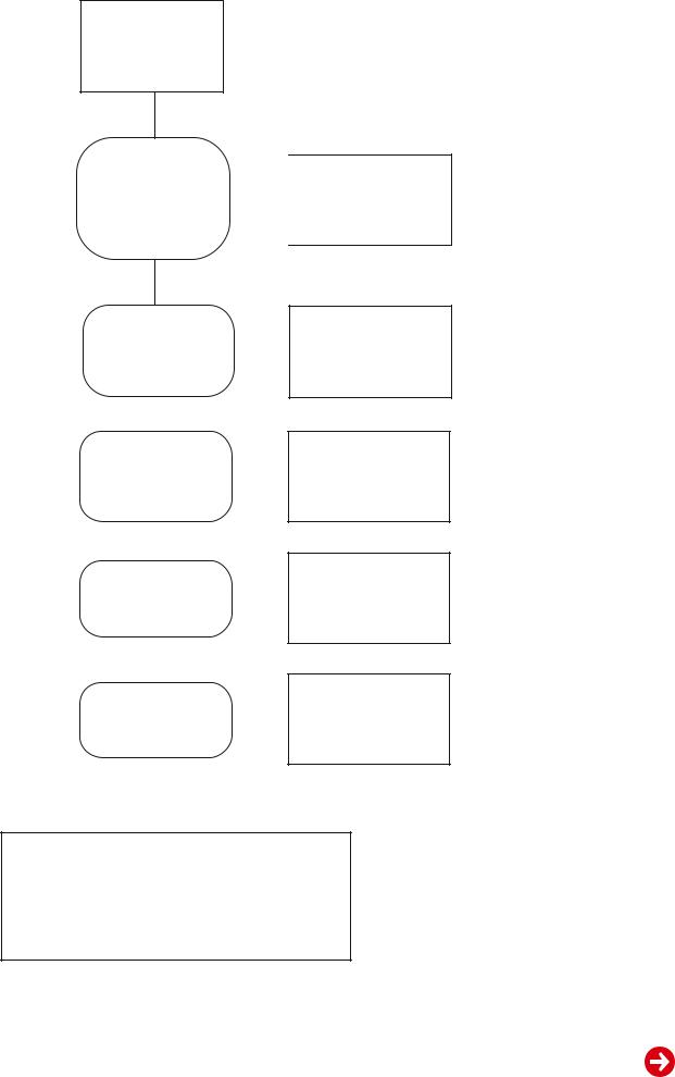
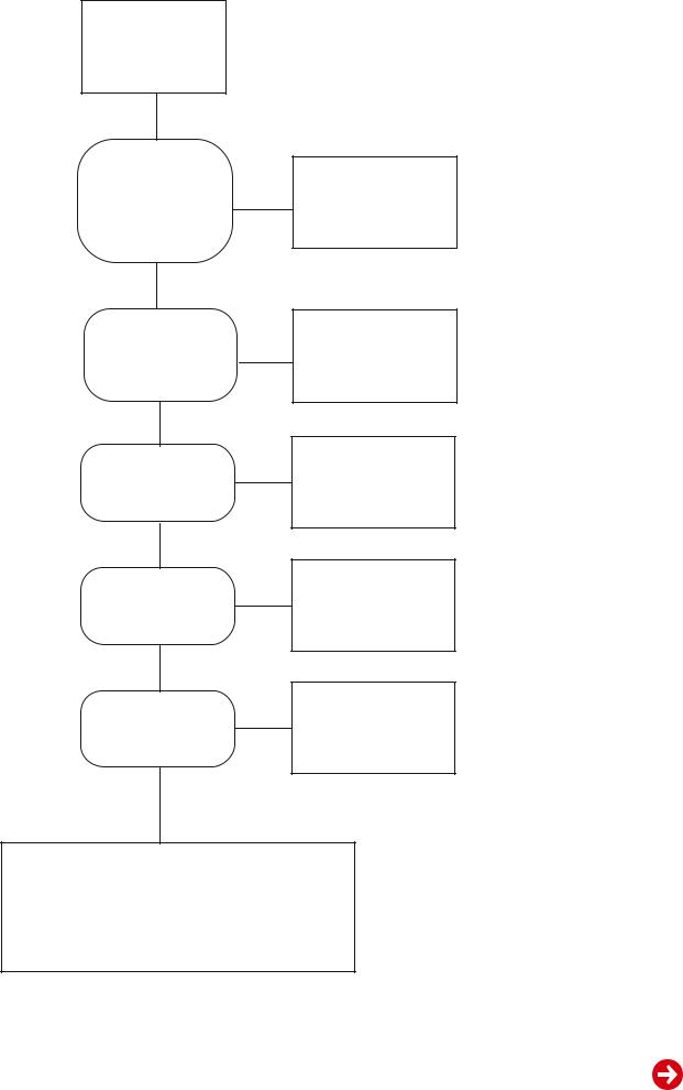
Fehlersuchdiagram
Backlight & LEDs
leuchten nicht
Sind Spannungen an |
|
||||
P803#10 = 5V & |
nein |
||||
P803#4 = 24V? |
|
||||
|
|||||
(Netzteil) |
|
||||
S. 2-2 |
|
||||
ja |
|
||||
Ist Spannung an |
nein |
||||
L139 = 24V? |
|||||
(Hauptplatte) |
|
||||
|
|||||
S. 2-9 |
|
||||
|
|
|
|
||
ja |
|
|
|
|
|
|
|
|
|
|
|
Ist Spannung an |
nein |
||||
L140 = 5V? |
|
||||
|
|
||||
(Hauptplatte) |
|
||||
S. 2-9 |
|
||||
|
|
|
|
||
ja |
|
|
|
|
|
|
|
|
|
|
|
Ist Spannung an |
nein |
||||
I016#2 = 3,3V? |
|
|
|||
|
|
||||
S. 2-9 |
|
||||
|
|
|
|
||
ja |
|
|
|
|
|
|
|
|
|
|
|
Ist Spannung an |
nein |
||||
I015#2 = 2,5V? |
|
|
|||
|
|
||||
S. 2-9 |
|
||||
|
|
|
|
||
ja |
|
|
|
|
|
|
|
|
|
|
|
Netzteil prüfen
Steckverbindungen
P803 & P019 prüfen
Steckverbindungen
P803 & P019 prüfen
I016 prüfen
I015 prüfen
Steckverbindungen
P601 (von LED-Platte zu P015) und P802A ( von Inverter zu P802) prüfen.
S. 2-2/2-18
1 - 5
GRUNDIG Service |
ARGANTO 23 LW 60-6410 Top |
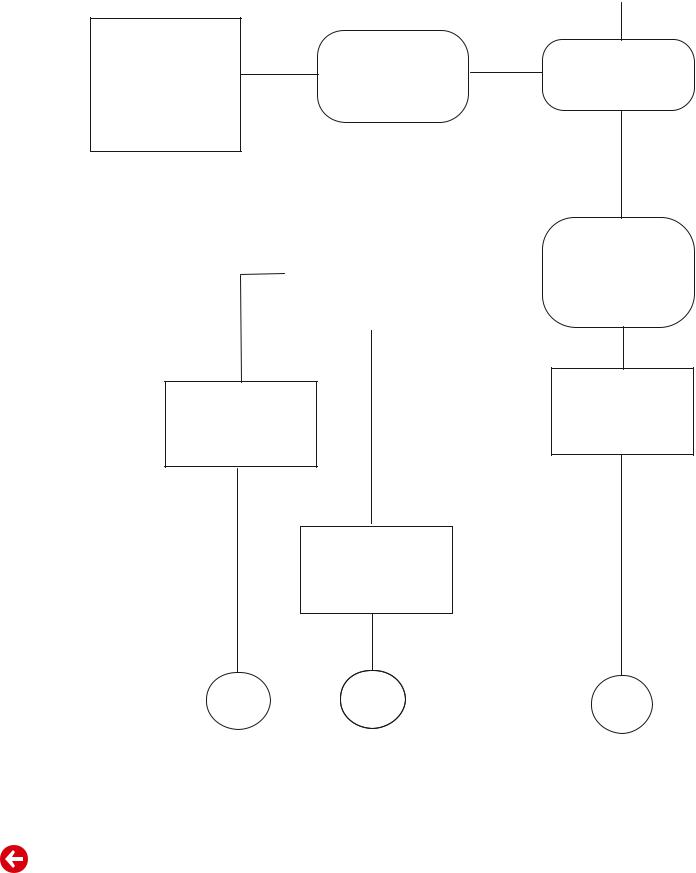
|
|
|
|
Kein Backlight, aber |
||
|
|
|
|
LED leuchtet |
||
|
Immer noch |
Steckverbinder |
|
|
|
|
|
|
|
|
|||
V901 (Panel mit Inverter) |
kein |
|
In welcher Farbe |
|||
P802 & P802A |
Grün |
|||||
Backlight |
||||||
und |
(von Netzteil |
|
|
|||
|
|
|
|
|||
I019 (Scaler) |
|
zum Inverter) |
|
leuchtet die LED? |
||
prüfen |
|
prüfen |
|
|
|
|
|
|
|
|
Rot |
||
|
Gerät ausschalten |
nein |
PC-Mode |
|
|
und vom Netz trennen, |
und |
||
|
|
|
||
|
um I012 (MCU) zu resetten. |
|
|
Energiesparmodus ein? |
Gerät |
|
|
|
|
funktioniert |
|
|
ja |
|
|
|
|
|
|
|
Gerät |
|
|
|
|
funktioniert |
|
|
|
|
|
|
||
|
nicht |
|
|
PC starten |
|
|
|
|
|
I012 (MCU) |
|
|
damit H. und V. Sync. |
|
|
|
vorhanden sind |
||
hängt sich zeitweise auf |
|
|
||
|
|
|
||
|
|
|
|
|
I012 (MCU) prüfen
Ende |
Ende |
Ende |
|
|
1 - 6
GRUNDIG Service |
ARGANTO 23 LW 60-6410 Top |
Fault Finding Diagram
No Backlight
&
No LED
Is the Voltage of P803#10 = 5V & P803#4 = 24V?
(on Power Module)
P. 2-2
Yes
Is the Voltage of
L139 = 24V?
(on Main Board)
P.2-9
Yes
Is the Voltage of
L140 = 5V?
(on Main Board)
P.2-9
Yes
Is the Voltage of
I016#2 = 3.3V?
P. 2-9
Yes
Is the Voltage of
I015#2 = 2.5V?
P. 2-9
Yes
No
No
No
No
No
Check PB0112V
(Power Module)
Check connectors P803 & P019
Check connectors P803 & P019
Check I016
Check I015
Check and Re-plug wires P601 (from LED Board to P015) and P802A (from Inverter to P802).
P. 2-2/2-18
1 - 7
GRUNDIG Service |
ARGANTO 23 LW 60-6410 Top |
No Backlight but
LED lights up
Check |
Still no |
|
|
|
|
|
|
|
|
||
Backlight |
Check & Re-plug |
Green |
Which Colour |
||
U901 (Inverter) |
|
P802 & P802 A |
|
||
|
|
does LED light? |
|||
and |
|
|
|||
|
(from Power to Inverter) |
|
|||
|
|
|
|
||
I019 (Scaler) |
|
|
|
|
|
|
|
|
|
|
|
|
|
|
|
Red |
|
|
Press POWER key & |
No |
Is it entering into |
|
|
Re-plug AC Power Cord |
Power Saving on |
||
|
|
|
||
|
|
|
||
|
to reset I012 (MCU) |
|
|
PC mode? |
Picture |
|
|
|
Yes |
Still no |
|
|
||
shows |
|
|
|
|
Picture |
|
|
|
|
I012 (MCU) |
|
|
Restart Signal to |
|
|
|
|
||
|
|
|
ensure H./V. sync. |
|
hangs |
|
|
|
|
|
|
|
are not absent |
|
temporarily |
|
|
|
|
|
|
|
|
|
|
|
|
|
|
Check
I012 (MCU)
End |
End |
End |
1 - 8

Schaltpläne und Platinenabbildungen / Circuit Diagrams and Layout of the PCBs
Blockschaltplan / Blockdiagram
UT01 |
SIF |
|
TV – Tuner |
||
Mono |
||
FQ1216 MK3 |
||
|
1 - 2
Scart-Video
Video
S-Video
Scart-RGB
Component
Video
4
I010 |
9 |
Interlace |
|
P15V330 |
|
Progressive |
|
PC VGA
|
|
|
I021 |
3 |
|
I044 |
3 |
Audio Amp. |
|
|
LA4282 |
|
||
|
|
|
||
TV Audio |
4:1 Audio Processor |
|
||
|
|
|||
|
MSP3410G |
|
|
|
|
ScartAudio |
Video/S-V/ Component Audio |
|
|
PC Audio |
I011 |
8 |
|
|
TT Decorder |
|
SAA5264PS |
|
I018 |
9 |
8 bit |
|
Decorder |
|||
|
|||
|
|
||
SAA7118E |
|
|
|
I006 |
2 |
24 bit Port B |
|
ADC |
|||
|
|||
|
|
||
AD9883-110 |
|
|
Component |
I034 |
3 |
|
||
|
P15V330 |
|
Audio Out |
|
|
|
|
|
10 |
|
|
I019 |
I014 |
|
Scaler |
|
|
LVDS |
|
|
TP6760 |
|
|
|
|
|
|
6 |
|
I001 |
1 |
24 bit Port A |
ADC |
|
|
|
|
|
AD9883-140 |
|
|
|
Remote Control |
|
AC Input |
|
|
100~240V |
7 |
|
Power |
||
50 / 60Hz |
||
~ |
Module |
+24V
+5V
+2.5V
+3.3V
LED & IR Pad |
|
Key Pad |
|
I013 |
5 |
|
|
EEPROM: 24C16 |
|
I012 |
5 |
|
MCU |
||
|
||
WE78162Ep |
||
(SyncMOS) |
|
|
5W + 5W Speaker
HeadphoneJack
Scart Audio Out
Line-out (RCA)
LCD Panel 16:9
INVERTER
Service GRUNDIG
Top 6410-60 LW 23 ARGANTO
 Loading...