


 Loading...
GRUNDFOS INSTRUCTIONS
MAGNA3
Installation and operating instructions

contents of Table
MAGNA3
English (US)
Installation and operating instructions. . . . . . . . . . . . . . . . . . . . . . . . . . . . . . . . . . . . . . . . . . . . . . . . . . . . . . . . . . . . 3
Español (MX)
Instrucciones de instalación y funcionamiento . . . . . . . . . . . . . . . . . . . . . . . . . . . . . . . . . . . . . . . . . . . . . . . . . . . . 46
Français (CA)
Notice d'installation et de fonctionnement. . . . . . . . . . . . . . . . . . . . . . . . . . . . . . . . . . . . . . . . . . . . . . . . . . . . . . . . 89
2
English (US) Installation and operating instructions
Original installation and operating instructions.
CONTENTS
|
|
Page |
1. |
Limited warranty |
4 |
2. |
Symbols used in this document |
4 |
3. |
General information |
5 |
3.1 |
Applications |
5 |
3.2 |
Pumped liquids |
5 |
3.3 |
Operating conditions |
6 |
3.4 |
Frost protection |
6 |
3.5 |
Insulating shells |
6 |
3.6 |
Non-return valve |
6 |
3.7 |
Nameplate |
7 |
3.8 |
Radio communication |
8 |
3.9 |
Tools |
8 |
4. |
Mechanical installation |
8 |
4.1 |
Installing the pump |
8 |
4.2 |
Positioning |
9 |
4.3 |
Control box positions |
9 |
4.4 |
Pump head position |
9 |
4.5 |
Changing the control box position |
10 |
5. |
Electrical installation |
11 |
5.1 |
Supply voltage |
12 |
5.2Connection to the power supply (models 40-XX,
|
50-XX, 65-XX, 80-XX, 100-XX) |
12 |
5.3 |
Connection to the power supply (models 32-XX) |
13 |
5.4 |
Connection diagram |
14 |
5.5 |
Input/output communication |
16 |
5.6 |
Analog input for external sensor |
18 |
5.7 |
Electrical connection for external sensor |
19 |
5.8 |
Priority of settings |
19 |
6. |
First start-up |
20 |
7. |
Settings |
21 |
7.1 |
Overview of settings |
21 |
8. |
Menu overview |
22 |
9. |
Control panel |
23 |
10. |
Menu structure |
23 |
11. |
"Home" menu |
23 |
12. |
"Status" menu |
24 |
13. |
"Settings" menu |
24 |
13.1 |
Setpoint |
24 |
13.2 |
Operating mode |
25 |
13.3 |
Control mode |
25 |
13.4 |
FLOWLIMIT |
29 |
13.5 |
Automatic Night Setback |
29 |
13.6 |
Relay outputs |
30 |
13.7 |
Setpoint influence |
30 |
13.8 |
Bus communication |
31 |
13.9 |
General settings |
31 |
14. |
"Assist" menu |
35 |
14.1 |
Assisted pump setup |
35 |
14.2 |
Setting of date and time |
35 |
14.3 |
Multi-pump setup |
35 |
14.4 |
Setup, analog input |
35 |
14.5 |
Description of control mode |
35 |
14.6 |
Assisted fault advice |
35 |
14.7 |
Wireless GENIair |
35 |
14.8 |
Multi-pump function |
35 |
15. |
Selection of control mode |
36 |
16. |
Fault finding |
38 |
16.1 |
Grundfos Eye operating indications |
38 |
16.2 |
Signalling communication with remote control |
38 |
16.3 |
Fault finding |
39 |
17. |
Sensor |
40 |
17.1 |
Sensor specifications |
40 |
18. |
Accessories |
41 |
18.1 |
Grundfos GO Remote |
41 |
18.2 |
Communication |
41 |
18.3 |
Fitting the CIM module |
44 |
19. |
Technical data |
45 |
20. |
Disposal |
45 |
|
|
|
Warning
Prior to installation, read these installation and operating instructions. Installation and operation must comply with local regulations and accepted codes of good practice.
Warning
The use of this product requires experience with and knowledge of the product.
Persons with reduced physical, sensory or mental capabilities must not use this product, unless they are under supervision or have been instructed in the use of the product by a person responsible for their safety.
Children must not use or play with this product.
English (US)
3
(US) English
1. Limited warranty
Products manufactured by GRUNDFOS PUMPS CORPORATION (Grundfos) are warranted to the original user only to be free of defects in material and workmanship for a period of 24 months from date of installation, but not more than 30 months from date of manufacture. Grundfos' liability under this warranty shall be limited to repairing or replacing at Grundfos' option, without charge, F.O.B. Grundfos' factory or authorized service station, any product of Grundfos' manufacture. Grundfos will not be liable for any costs of removal, installation, transportation, or any other charges which may arise in connection with a warranty claim. Products which are sold but not manufactured by Grundfos are subject to the warranty provided by the manufacturer of said products and not by Grundfos' warranty. Grundfos will not be liable for damage or wear to products caused by abnormal operating conditions, accident, abuse, misuse, unauthorized alteration or repair, or if the product was not installed in accordance with Grundfos' printed installation and operating instructions.
To obtain service under this warranty, the defective product must be returned to the distributor or dealer of Grundfos' products from which it was purchased together with proof of purchase and installation date, failure date, and supporting installation data. Unless otherwise provided, the distributor or dealer will contact Grundfos or an authorized service station for instructions.
Any defective product to be returned to Grundfos or a service station must be sent freight prepaid; documentation supporting the warranty claim and/or a Return Material Authorization must be included if so instructed.
GRUNDFOS WILL NOT BE LIABLE FOR ANY INCIDENTAL OR CONSEQUENTIAL DAMAGES, LOSSES, OR EXPENSES ARISING FROM INSTALLATION, USE, OR ANY OTHER CAUSES. THERE ARE NO EXPRESS OR IMPLIED WARRANTIES, INCLUDING MERCHANTABILITY OR FITNESS FOR A PARTICULAR PURPOSE, WHICH EXTEND BEYOND THOSE WARRANTIES DESCRIBED OR REFERRED TO ABOVE.
Some jurisdictions do not allow the exclusion or limitation of incidental or consequential damages and some jurisdictions do not allow limit actions on how long implied warranties may last. Therefore, the above limitations or exclusions may not apply to you. This warranty gives you specific legal rights and you may also have other rights which vary from jurisdiction to jurisdiction.
2. Symbols used in this document
Warning
If these safety instructions are not observed, it may result in personal injury.
Warning
If these instructions are not observed, it may lead to electric shock with consequent risk of serious personal injury or death.
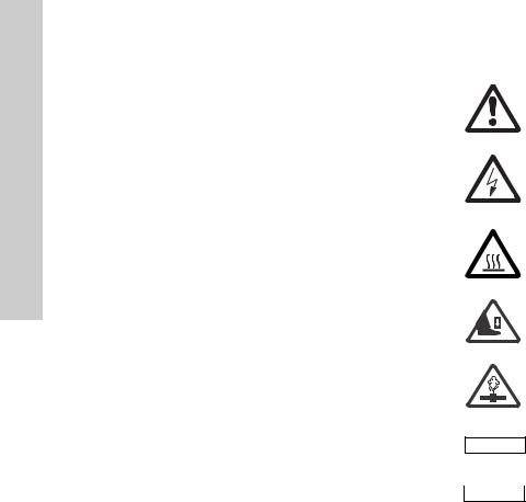
Warning
The surface of the product may be so hot that it may cause burns or personal injury.
Warning
Risk of dropping objects which may cause personal injury.
Warning
Escaping vapor involves the risk of personal injury.
If these safety instructions are not observed,
Caution it may result in malfunction or damage to the |
||
|
equipment. |
|
Note |
Notes or instructions that make the job easier |
|
and ensure safe operation. |
||
|
||
4
3. General information
The Grundfos MAGNA3 is a complete range of circulator pumps with integrated controller enabling adjustment of pump performance to the actual system requirements. In many systems, this will reduce the power consumption considerably, reduce noise from thermostatic radiator valves and similar fittings and improve the control of the system.
The desired head can be set on the pump control panel.
3.1 Applications
The Grundfos MAGNA3 is designed for circulating liquids in the following systems:
•heating systems
•domestic hot-water systems
•air-conditioning and cooling systems.
The pump can also be used in the following systems:
•ground source heat pump systems
•solar-heating systems.
3.2 Pumped liquids
The pump is suitable for thin, clean, non-aggressive and non-explosive liquids, not containing solid particles or fibers that may attack the pump mechanically or chemically.
In heating systems, the water should meet the requirements of accepted standards on water quality in heating systems.
In domestic hot-water systems, we recommend to use MAGNA3 pumps only for water with a degree of hardness lower than approx. 14 °dH.
In domestic hot-water systems, we recommend to keep the liquid temperature below 150 °F (+65 °C) to eliminate the risk of lime precipitation.
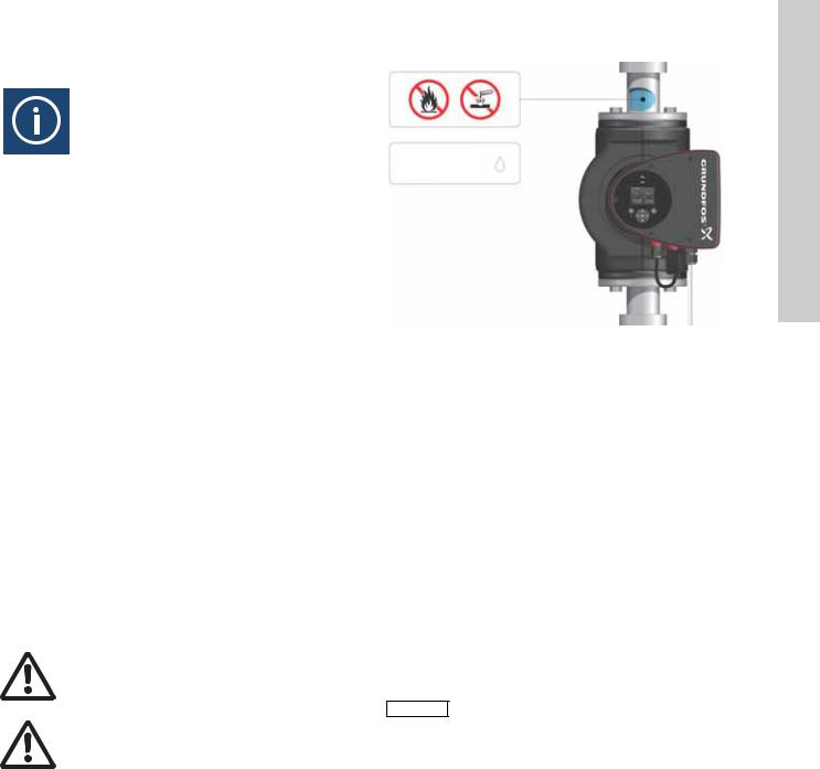
Warning
Do not use the pump for flammable liquids, such as diesel oil and gasoline.
Warning
Do not use the pump for aggressive liquids, such as acids and sea water.
Max. 95 % RH
Enclosure Type 2
TM05 2857 0612
Fig. 1 Pumped liquids
3.2.1 Glycol
The pump can be used for pumping water/glycol mixtures up to 50 %.
Example of a water/ethylene glycol mixture:
Maximum viscosity: 50 cSt ~ 50 % water / 50 % ethylene glycol mixture at +14 °F (-10 °C).
The pump has a power-limiting function that protects against overload.
The pumping of glycol mixtures will affect the max. curve and reduce the performance, depending on the water/ethylene glycol mixture and the liquid temperature.
To prevent the ethylene glycol mixture from degrading, avoid temperatures exceeding the rated liquid temperature and minimize the operating time at high temperatures.
It is important to clean and flush the system before the ethylene glycol mixture is added.
To prevent corrosion or lime precipitation, check and maintain the ethylene glycol mixture regularly. If further dilution of the supplied ethylene glycol is required, follow the glycol supplier's instructions.
Additives with a density and/or kinematic Note viscosity higher than those/that of water will
reduce the hydraulic performance.
English (US)
5
(US) English
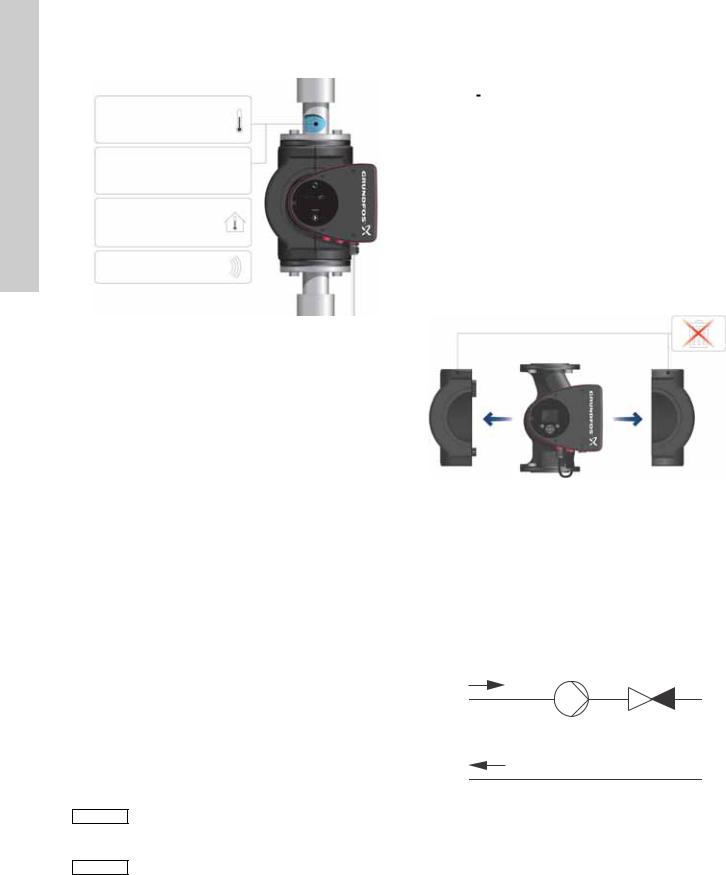
3.3Operating conditions
1Min./Max. +14 °F - 230 °F (-10 °C - +110 °C)
2 |
175 psi (12 bar) |
|
|
3 |
+32 to +104 °F |
|
|
(0 to +40 °C) |
|
||
|
|
||
4 |
< 43 dB(A) |
1413 |
|
TM05 7662 |
|||
|
|
Fig. 2 Operating conditions
3.3.1Liquid temperature
See fig. 2, pos. 1.
Continuously: +14 °F to +230 °F (-10 °C to +110 °C). Domestic hot-water systems:
• Up to +150 °F (+65 °C).
3.3.2System pressure
See fig. 2, pos. 2.
The maximum permissible system pressure is stated on the pump nameplate.
3.3.3 Ambient temperature
See fig. 2, pos. 3.
+32 °F to +104 °F (0 °C to +40 °C).
The control box is air-cooled. Therefore, it is important that the maximum permissible ambient temperature is not exceeded during operation.
During transport: -40 °F to +158 °F (-40 °C to +70 °C).
3.3.4Sound pressure level
See fig. 2, pos. 4.
The sound pressure level of the pump is lower than 43 dB(A).
3.3.5Approvals
•Conforms to ANSI/UL Standard 778.
•Certified to CAN/CSA Standard C22.2 No. 108.
• The protective earth (ground) symbol  identifies any terminal which is intended for connection to an external conductor for protection against electric shock in case of a fault, or the terminal of a protective earth (ground) electrode.
3.4 Frost protection
If the pump is not used during periods of frost, Caution necessary steps must be taken to prevent frost
bursts.
Additives with a density and/or kinematic Note viscosity higher than those/that of water will
reduce the hydraulic performance.
3.5 Insulating shells
Insulating shells are available for single-head pumps only.
|
Limit the heat loss from the pump housing and |
|
Note |
||
pipework. |
||
|
The heat loss from the pump and pipework can be reduced by insulating the pump housing and the pipework. See fig. 3 and fig. 13.
•Insulating shells for pumps in heating systems are supplied with the pump; see fig. 3.
•For pumps in air-conditioning and cooling systems (down to +14 ° (-10 °C)) it is required to apply a silicon sealant to the internal contours of the shell in order to eliminate any air gaps and prevent condensation between the insulation shell and pump housing. Alternatively, the pump can also be insulated manually in accordance with standard insulating requirements for heating and cooling systems (fig. 13).
The fitting of insulating shells will increase the pump dimensions.
TM05 2859 0612
Fig. 3 Fitting insulating shells to the pump
|
Do not insulate the control box or cover the |
Caution |
|
|
control panel. |
|
3.6 Non-return valve
If a non-return valve is fitted in the pipe system (fig. 4), it must be ensured that the set minimum discharge pressure of the pump is always higher than the closing pressure of the valve. This is especially important in proportional-pressure control mode (reduced head at low flow). The closing pressure of a single non-return valve is accounted for in the pump settings as the minimum head delivered is 5 ft (1.5 m).
TM05 3055 0912
Fig. 4 Non-return valve
6
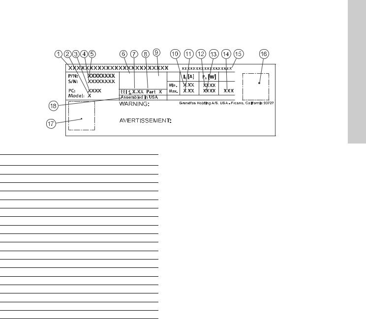
3.7 Nameplate
The pump nameplate provides the following information:
TYPE 2 |
PSI |
BOITIER DE TYPE 2 |
|
THERMALLY PROTECTED |
|
Nonsubmersible Pump |
|
|
For use with maximum 230° F water |
RISK OF ELECTRIC SHOCK. DE-ENERGIZE EQUIPMENT BEFORE REMOVAL OF COVER & SERVICING. FOR SUPPLY
CONNECTION USE COPPER WIRE SUITABLE FOR 90 °C OR EQUIVALENT. THIS PUMP HAS NOT BEEN INVESTIGATED FOR USE
IN SWIMMING POOL OR MARINE AREAS. TO REDUCE THE RISK OF ELECTRIC SHOCK, SEE INSTRUCTION MANUAL FOR
PROPER INSTALLATION; ACCEPTABLE FOR INDOOR USE ONLY.
RISQUE DE CHOC ELECTRIQUE. HORS DES EQUIPEMENT AVANT ENLEVEMENT DE LA COUVERTURE ET D’ENTRENTIEN. POUR
LE RECCORDEMENT D’ALIMENTATION, EMPLOYEZ DES FILS QUI RESISTENT AU MOINS A 90 °C UTILISEZ UNIQUEMENT DES
CONDUCTEURS DE CUIVRE. POUR RE’DUIRE LES RISQUES DE CHOC E’LECTRIQUE, CONSULTES LE MANUEL D’INSTRUCTIONS
Contains FCC ID: OG3-RADIOM01-2G4 POUR UNE INSTALLATION CORRECTE. EMPLOYER UNIQUEMENT A L’INTERIEUR.
Fig. 5 Example of nameplate
Pos. Description
1Product name
2Model
3Production code (year and week)
4Serial number
5Product number
6Enclosure type
7Energy Efficiency Index (EEI)
8Part (according to EEI)
9TF-class
10Minimum current [A]
11Maximum current [A]
12Minimum power [W]
13Maximum power [W]
14Maximum pressure
15Voltage [V] and frequency [Hz]
16QR (Quick Response) code
17Approvals (nameplate)
18Assembled in USA
English (US)
TM05 6381 4612
7
(US) English
3.8 Radio communication
The wireless radio in this product is class B.
Intended use
This product incorporates a radio for remote control.
The product can communicate with Grundfos Go Remote and with other MAGNA3 pumps of the same type via the built-in radio.
Only Grundfos-approved external antennae may be connected to this product, and only by a Grundfos-approved installer.
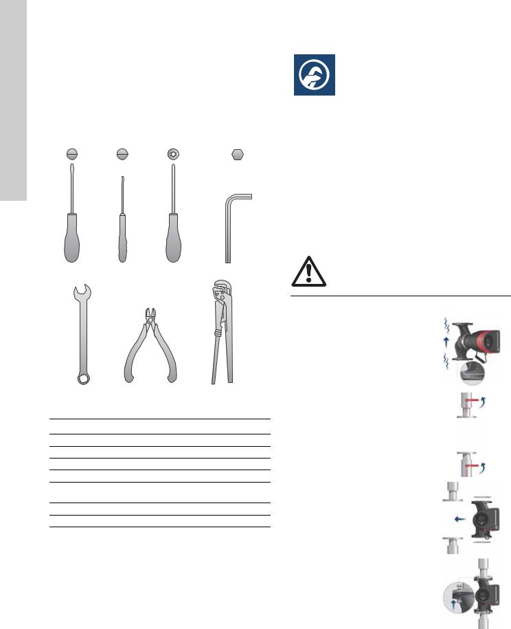
3.9 Tools
1.2 x 8.0 |
0.6 x 3.5 |
TX20 |
5.0 |
1 |
2 |
3 |
4 |
|
5 |
6 |
7 |
TM05 6472 4712 |
Fig. 6 |
Recommended tools |
|
|
|
Pos. |
Tool |
|
Size |
|
1 |
Screwdriver, straight slot |
1.2 x 8.0 mm |
|
|
2 |
Screwdriver, straight slot |
0.6 x 3.5 mm |
|
|
3 |
Screwdriver, torx bit |
|
TX20 |
|
4 |
Hexagon key |
|
5.0 mm |
|
5 |
Open-end wrench |
|
Depending on flange bolt |
|
|
size |
|
||
|
|
|
|
|
6 |
Wire cutter |
|
|
|
7 |
Pipe wrench |
|
|
|
4. Mechanical installation
4.1 Installing the pump
MAGNA3 is designed for indoor installation.
The pump must be installed in such a way that it is not stressed by the pipework.
The pump may be suspended direct in the pipes, provided that the pipework can support the pump.
Twin-head pumps are prepared for installation on a mounting bracket or base plate.
To ensure adequate cooling of motor and electronics, the following must be observed:
•Position the pump in such a way that sufficient cooling is ensured.
•The temperature of the ambient air must not exceed +104 °F (+40 °C).
Warning
Observe local regulations setting limits for manual lifting or handling.
Step |
Action |
Illustration |
|
|
|
|
|
|
Arrows on the pump housing |
|
|
|
indicate the liquid flow direction |
|
|
1 |
through the pump. The liquid |
0612 |
|
flow direction can be horizontal |
|||
|
2862 |
||
|
or vertical, depending on the |
||
|
|
||
|
control box position. |
TM05 |
|
|
|
||
|
|
|
|
|
Close the isolating valves and |
|
|
2 |
make sure that the system is not |
0612 |
|
pressurized during the |
|||
|
|||
|
|
||
|
installation of the pump. |
TM05 2863 |
|
|
|
||
|
|
|
|
3 |
Mount the pump with gaskets in |
0612 |
|
the pipework. |
|||
|
TM05 2864 |
||
|
|
||
|
|
|
|
|
Fit bolts and nuts. Use the right |
0612 |
|
4 |
size of bolts according to system |
||
|
pressure. |
TM05 2865 |
|
|
|
||
|
|
|
8

4.2 Positioning
Always install the pump with horizontal motor shaft.
•Pump installed correctly in a vertical pipe. See fig. 7, pos. A.
•Pump installed correctly in a horizontal pipe. See fig. 7, pos. B.
•Do not install the pump with vertical motor shaft. See fig. 7, pos. C and D.
A B
C D
TM05 2866 0712
Fig. 7 Pump installed with horizontal motor shaft
4.3 Control box positions
To ensure adequate cooling, the control box must be in horizontal position with the Grundfos logo in vertical position. See fig. 8.
TM05 2915 0612
Fig. 8 Pump with control box in horizontal position
If the pump head is removed before the pump is installed in the pipework, pay special attention when fitting the pump head to the pump housing:
1.Gently lower the pump head with rotor shaft and impeller into the pump housing.
2.Make sure that the contact face of the pump housing and that of the pump head are in contact before the clamp is tightened. See fig. 9.
TM05 5837 4112
Fig. 9 Fitting the pump head to the pump housing
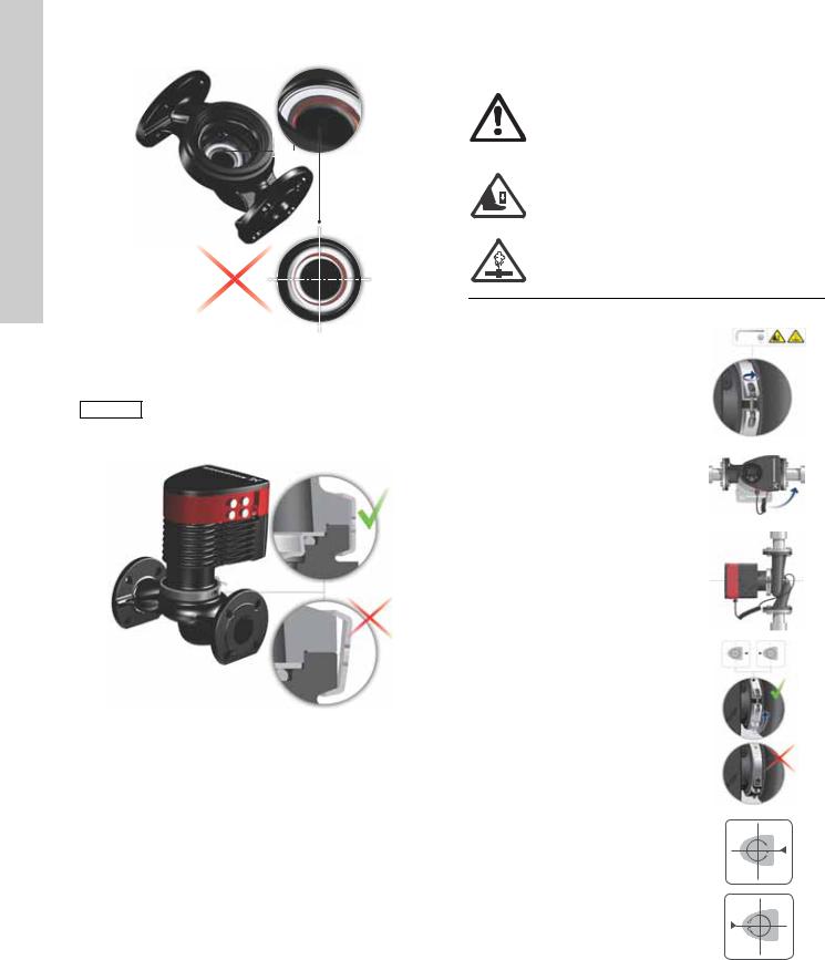
4.4 Pump head position
If the pump head is removed before the pump is installed in the pipework, pay special attention when fitting the pump head to the pump housing:
3.Visually check that the floating ring in the sealing system is centered. See figs. 10 and 11.
4.Gently lower the pump head with rotor shaft and impeller into the pump housing.
5.Make sure that the contact face of the pump housing and that of the pump head are in contact before the clamp is tightened. See fig. 12.
TM05 6650 5012
Fig. 10 Correctly centered sealing system
English (US)
9
(US) English
TM05 6651 5012
Fig. 11 Incorrectly centered sealing system
Observe the position of the clamp before the clamp is tightened. Incorrect position of the Caution clamp will cause leakage from the pump and
damage the hydraulic parts in the pump head. See fig. 12.
TM05 5837 4112
Fig. 12 Fitting the pump head to the pump housing
4.5 Changing the control box position
Warning
The warning symbol on the clamp holding the pump head and pump housing together indicates that there is a risk of personal injury. See specific warnings below.
Warning
When loosening the clamp, do not drop the pump head.
Warning
Risk of escaping vapor.
Step |
Action |
Illustration |
|||||||
|
|
|
|
|
|
|
|
|
|
|
Loosen the screw in the clamp |
|
|
|
|
|
|
|
|
|
holding the pump head and pump |
|
|
|
|
|
|
|
|
|
housing together. |
0612 |
|||||||
1 |
Warning: If the screw is loosened |
||||||||
|
too much, the pump head will be |
2867 |
|||||||
|
completely disconnected from the |
||||||||
|
|
|
|
|
|
|
TM05 |
||
|
pump housing. |
|
|
|
|
|
|
||
|
|
|
|
|
|
|
|
||
|
|
|
|
|
|
|
|
|
|
|
Carefully rotate the pump head to |
0612 |
|||||||
|
the desired position. |
||||||||
|
2868 |
||||||||
2 |
If the pump head is stuck, loosen it |
||||||||
|
|
|
|
|
|
|
|||
|
with a light blow of a rubber |
|
|
|
|
|
|
TM05 |
|
|
mallet. |
|
|
|
|
|
|
||
|
|
|
|
|
|
|
|
|
|
|
Position the control box in |
0612 |
|||||||
|
horizontal position so that the |
||||||||
3 |
Grundfos logo is in vertical |
||||||||
2869 |
|||||||||
|
position. The motor shaft must be |
||||||||
|
horizontal. |
|
|
|
|
|
|
TM05 |
|
|
|
|
|
|
|
|
|
||
|
|
|
|
|
|
|
|
|
|
|
Due to the drain hole in the stator |
|
|
|
|
|
|
|
|
4 |
housing, position the gap of the |
|
|
|
|
|
|
|
|
clamp as shown in step 4a, 4b, 4c |
|
|
|
|
|
|
|
||
|
|
|
|
|
|
|
TM05 2870 0612 |
||
|
or 4d. |
|
|
|
|
|
|
||
|
|
|
|
|
|
|
|
||
|
|
|
|
|
|
|
|
|
|
|
Single-head pump. |
|
|
|
|
|
2871 0612 |
||
|
|
|
|
|
|
||||
|
|
|
|
|
|
||||
|
|
|
|
|
|
|
TM05 |
||
4a |
Position the clamp so that the gap |
|
|
|
|
|
|
||
- |
|||||||||
points towards the arrow. |
|||||||||
|
|
|
|
|
|
|
0612 |
||
|
|
|
|
|
|
|
|||
|
It can be in position 3 or 9 o'clock. |
|
|
|
|
|
|
||
|
|
|
|
|
|
|
TM05 2918 |
||
|
|
|
|
|
|
|
|
||
|
|
|
|
|
|
|
|
|
|
10
Step |
Action |
Illustration |
||||||
|
|
|
|
|
|
|
||
|
Single-head pump. |
|
|
|
|
|
||
|
Note: The gap of the clamp can |
|
|
|
|
|
||
|
also be in position 6 o'clock for the |
|
|
|
|
|
||
|
1912 |
|||||||
4b |
following pump sizes: |
|||||||
|
• |
MAGNA3 65-XX |
2899 |
|||||
|
|
|
|
|
|
|||
|
• |
MAGNA3 80-XX |
|
|
|
|
TM05 |
|
|
• |
MAGNA3 100-XX. |
|
|
|
|
||
|
|
|
|
|
|
|
|
|
|
Twin-head pump. |
2873 0612 |
||||||
|
|
|
|
|
TM05- |
|||
|
Position the clamps so that the |
|
|
|
|
|||
|
|
|
|
|
|
|||
4c |
gaps point towards the arrows. |
0612 |
||||||
|
They can be in position 3 or |
|||||||
|
|
|
|
|
|
|||
|
9 o'clock. |
|
|
|
|
TM05 2917 |
||
|
|
|
|
|
|
|
|
|
|
|
|
|
|
|
|
||
|
Twin-head pump. |
|
|
|
|
|
||
|
Note: The gap of the clamp can |
|
|
|
|
|
||
|
also be in position 6 o'clock for the |
1912 |
||||||
4d |
following pump sizes: |
|||||||
|
• |
MAGNA3 65-XX |
2897 |
|||||
|
|
|
|
|
|
|||
|
• |
MAGNA3 80-XX |
|
|
|
|
TM05 |
|
|
• |
MAGNA3 100-XX. |
|
|
|
|
||
|
Fit and tighten the screw holding |
0612 |
||||||
6 |
the clamp to minimum |
|||||||
|
6 ± 0.7 ft-lbs (8 ± 1 Nm). |
|
|
|
|
TM05 2872 |
||
|
|
|
|
|
|
|
|
|
|
|
|
|
|
|
|
||
|
Fit the insulating shells. |
|
|
|
|
|
||
|
Note: For air conditioning and |
|
|
|
|
|
||
|
cooling systems a silicone sealant |
|
|
|
|
|
||
|
must be applied inside the |
|
|
|
|
|
||
|
insulation shell to eliminate all air |
|
|
|
|
|
||
7 |
gaps and prevent condensation |
|
|
|
|
|
||
between the pump housing and |
|
|
|
|
|
|||
|
0412 |
|||||||
|
insulation shell. Alternatively, the |
|||||||
|
|
|
|
|
|
|||
|
pump may be insulated manually |
2874 |
||||||
|
in accordance with standard |
|||||||
|
insulation practices for cooling |
|
|
|
|
TM05 |
||
|
applications. |
|
|
|
|
|||
|
|
|
|
|
|
|||
|
|
|
If insulating the pump manually, do not insulate |
|||||
Caution |
|
|||||||
|
|
|
the control box or cover the control panel. |
|||||
|
|
|
||||||
TM05 5549 3812
Fig. 13 Insulation of pump housing and pipework
5. Electrical installation
Carry out the electrical connection and protection according to local regulations.
Check that the supply voltage and frequency correspond to the values stated on the nameplate.
Warning
Never make any connections in the pump control box unless the power supply has been switched off for at least 5 minutes.
Warning
The pump must be connected to an external mains switch with a contact separation of at least 1/8 inch (3 mm) in each pole.
The ground terminal of the pump must be connected to ground. Grounding or neutralization can be used for protection against indirect contact.
If the pump is connected to an electric installation where a Ground Fault Circuit Interrupter (GFCI) is used as additional protection, this circuit interrupter must trip out when ground fault currents with DC content (pulsating DC) occur.
•If rigid conduit is to be used, the hub must be connected to the conduit system before it is connected to the terminal box of the pump.
•The pump must be connected to an external mains switch.
•The pump requires no external motor protection.
•The motor incorporates thermal protection against slow overloading and blocking.
•When switched on via the power supply, the pump will start pumping after approx. 5 seconds.
Note |
The number of starts and stops via the power |
|
supply must not exceed four times per hour. |
||
|
English (US)
11
(US) English
5.1 Supply voltage
1 x 115 V ± 10 %, 50/60 Hz, PE.
1 x 208-230 V ± 10 %, 50/60 Hz, PE.
See pump nameplate for rated supply voltage
The voltage tolerances are intended for mains voltage variations. They should not be used for running pumps at other voltages than those stated on the nameplate.
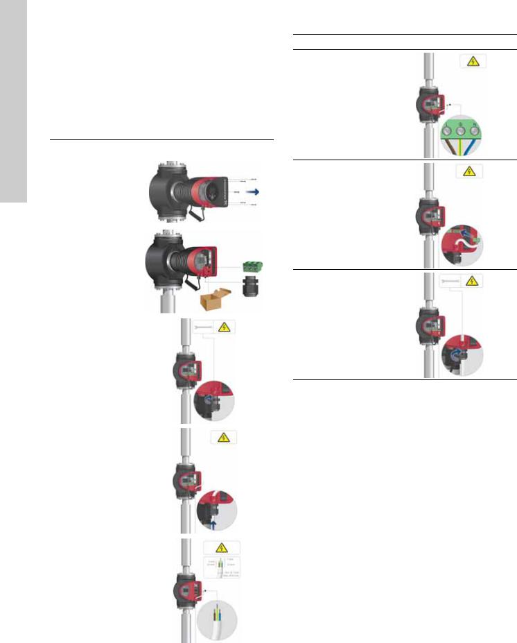
5.2Connection to the power supply (models 40-XX, 50-XX, 65-XX, 80-XX, 100-XX)
Step |
Action |
Illustration |
|
|
|
|
|
|
Remove the front |
0612 |
|
1 |
cover from the |
||
2875TM05 |
|||
|
control box. |
||
|
|
||
|
|
|
|
|
Locate the power |
|
|
|
supply plug and |
|
|
2 |
conduit adapter in |
0612 |
|
|
the box supplied |
||
|
2876TM05 |
||
|
with the pump. |
||
|
|
||
|
|
|
|
|
Connect the |
|
|
3 |
conduit adapter to |
|
|
|
the control box. |
TM05 2877 0612 |
|
|
|
||
|
|
|
|
|
Pull the power |
|
|
4 |
supply cable |
|
|
through the |
|
||
|
06122878TM05 |
||
|
conduit adapter. |
||
|
|
||
|
|
|
|
|
Strip the cable |
|
|
5 |
conductors as |
|
|
|
illustrated. |
TM05 5534 3812 |
|
|
|
||
|
|
|
Step Action |
Illustration |
Connect the cable conductors to the
6power supply plug. L - L or L1 Ground - Ground N - N or L2
Insert the power supply plug into
7the male plug in the pump control box.
Tighten the
8conduit adapter. Refit the front cover.
TM05 2880 0612
TM05 2881 0612
TM05 2882 0612
12
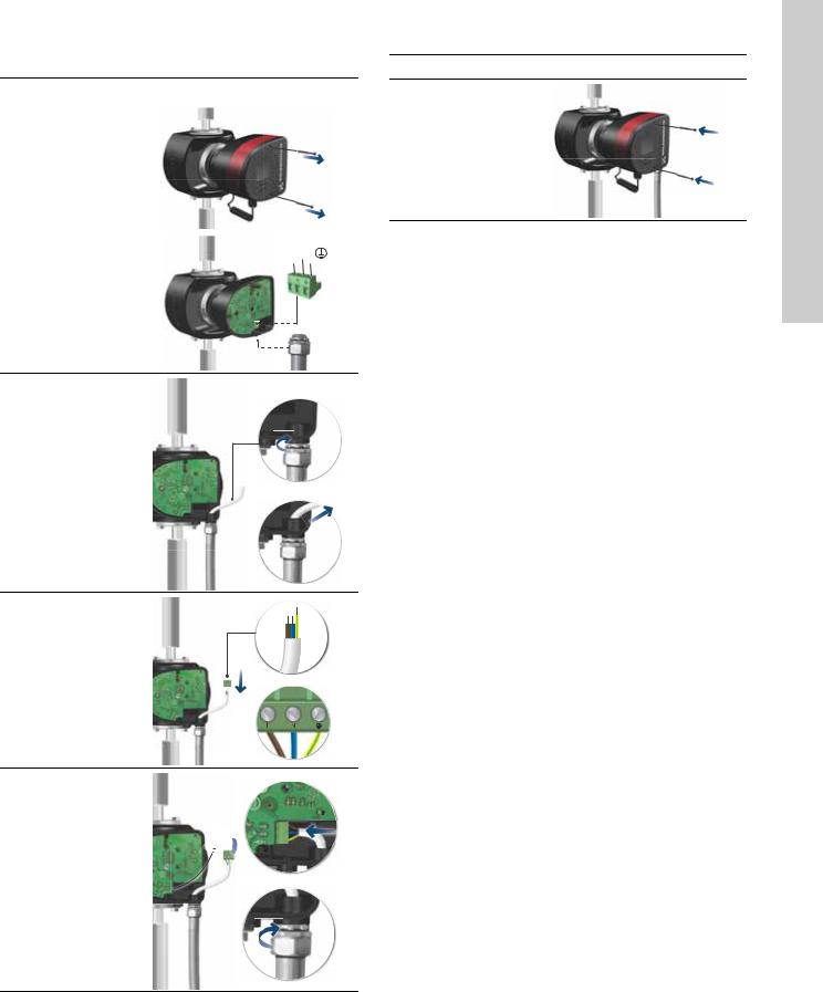
5.3 Connection to the power supply (models 32-XX)
Step |
Action |
Illustration |
|||||||
|
|
|
|
|
|
|
|
|
|
|
Remove two |
|
|
|
|
|
|
|
|
|
screws. |
|
|
|
|
|
|
|
|
|
Remove the front |
1614 |
|||||||
1 |
cover from the |
||||||||
|
|
|
|
|
|
|
|||
|
control box and |
1102 |
|||||||
|
access the power |
||||||||
|
connection. |
|
|
|
|
|
|
TM06 |
|
|
|
|
|
|
|
|
|
||
|
|
|
|
|
|
|
|
|
|
2 |
Locate the power |
L (L1) N (L2) |
|
|
16141103TM06 |
||||
|
|
||||||||
|
|
|
|
|
|
||||
|
|
|
|
|
|
||||
plug inside. |
|
|
|
|
|
|
|||
|
|
|
|
|
|
|
|||
|
|
|
|
|
|
|
|
||
Connect the conduit to the control box.
3Pull the power supply cable through the conduit.
Strip the cable as illustrated.
Connect the cable
5conductors to the power supply plug. L - L or L1 Ground - Ground N - N or L2
Insert the power plug into its mating
6connector.
Tighten the conduit.
 TM06 1104 1614
TM06 1105 1614
TM06 1106 1614
Step Action |
Illustration |
7Refit the front cover.
TM06 1107 1614
English (US)
13
(US)English |
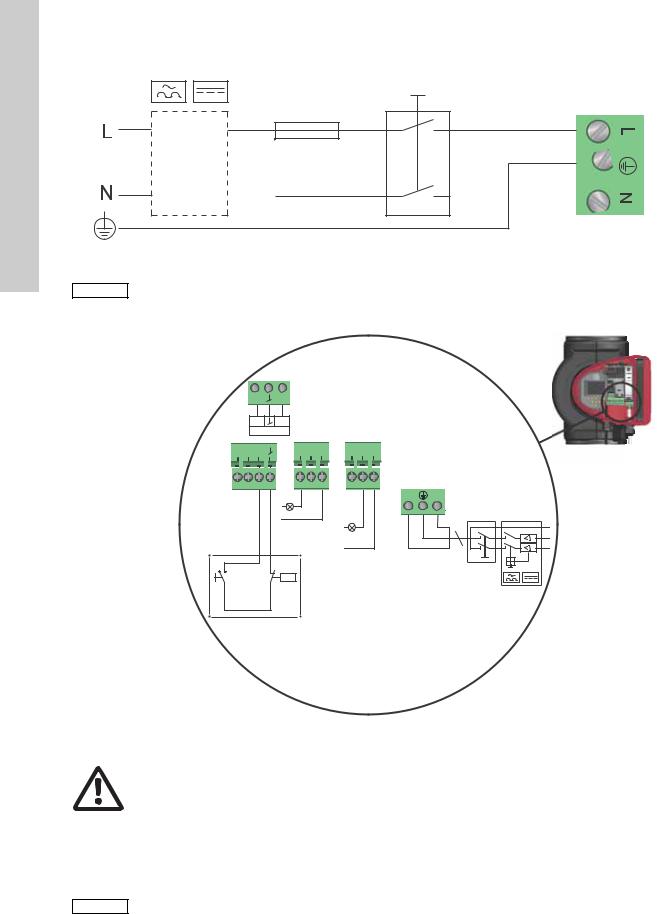
5.4 Connection diagram |
|
External switch |
||
|
||
|
GFCI |
|
|
Fuse |
|
|
(min. 10 A, time lag) |
Fig. 14 |
Example of typical connection, 1 x 230 V ± 10 %, 50/60 Hz |
|
|
|||
Note |
All cables used must be connected in accordance with local regulations. |
|||||
5.4.1 Connection to external controllers |
|
|
|
|||
|
|
|
Analog input |
|
|
|
|
|
24V |
IN |
|
|
|
|
|
Vcc |
signal |
|
|
|
|
|
sensor |
|
|
|
|
|
M |
M |
NC NO C |
NC NO C |
|
|
|
A |
I S/S |
|
|
||
|
|
|
|
L |
N |
Mains |
|
|
|
|
|
||
|
|
|
Alarm |
|
|
connection |
|
|
|
|
|
|
|
|
|
|
Operation |
|
|
|
|
Start/ |
On/off timer |
|
|
||
|
stop |
|
|
|
|
|
Fig. 15 Example of connections in the control box
Warning
Wires connected to supply terminals, outputs NC, NO, C and start/stop input must be separated
from each other and from the supply by reinforced insulation.
Concerning demands on signal wires and signal transmitters, see section 19. Technical data.
Use screened cables for external on/off switch, digital input, sensor and setpoint signals.
Note |
All cables used must be heat-resistant up to |
|
+185 °F (+85 °C). |
||
|
TM03 2397 0312
TM05 2673 3812
14
English (US)
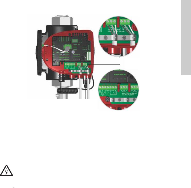
TM05 8539 2413
Fig. 16 Wiring diagram, 32-XX versions
The connection terminals of 32-XX versions differ from those of terminal-connected versions, but they have the same function and connection options.
Use screened cables for external on/off switch, digital input, sensor and setpoint signals.
Connect screened cables to the ground connection as follows:
•Terminal-connected versions:
Connect the cable screen to ground via the digital-input terminal (earth).
•Plug-connected versions:
Connect the cable screen to ground via cable clamp.
|
Warning |
|
|
Wires connected to supply terminals, outputs |
|
|
NC, NO, C and start/stop input must be separated |
|
|
from each other and from the supply by |
|
|
reinforced insulation. |
|
|
All cables used must be heat-resistant up to |
|
|
+85 °C. |
|
Note |
||
All cables used must be installed in accordance |
||
|
||
|
with EN 60204-1 and EN 50174-2:2000. |
15
(US) English
5.5 Input/output communication
•Relay outputs
Alarm, ready and operating indication via signal relay.
•Digital input
–Start/Stop (S/S)
–Min. curve (MI)
–Max. curve (MA).
•Analog input
0-10 V or 4-20 mA control signal.
To be used for external control of the pump or as sensor input for the control of the external setpoint.
The 24 V supply from pump to sensor is optional and is normally used when an external supply is not available.
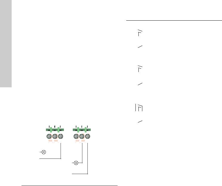
5.5.1 Relay outputs
See fig. 15, pos. 1.
The pump incorporates two signal relays with a potential-free changeover contact for external fault indication.
The function of the signal relay can be set to "Alarm", "Ready" or "Operation" on the pump control panel or with Grundfos GO Remote.
The relays can be used for outputs up to 250 V and 2 A.
Relay 1 |
|
Relay 2 |
|||||||||
|
|
|
|
|
|
|
|
|
|
|
|
NC NO C |
|
NC NO C |
|||||||||
|
|
|
|
|
|
|
|
|
|
|
|
|
|
|
|
|
|
|
|
|
|
|
|
|
|
|
|
|
|
|
|
|
|
|
|
|
|
|
|
|
|
|
|
|
|
|
|
The functions of the signal relays appear from the table below:
Signal relay |
Alarm signal |
|||||||||
|
|
|
|
|
|
|
|
|
|
|
|
|
|
|
|
|
|
|
|
Not activated: |
|
|
|
|
|
|
|
|
|
|
||
|
|
|
|
|
|
|
|
|
||
|
|
1 |
2 |
3 |
|
|
|
• |
The power supply has been switched off. |
|
|
|
NC NO |
C |
C |
|
• |
The pump has not registered a fault. |
|||
|
NC NO |
|
|
|||||||
|
1 |
2 |
|
3 |
|
|
|
|||
|
|
|
|
|
|
|
|
|
|
|
|
|
|
|
|
|
|
|
|
Activated: |
|
|
|
|
|
|
|
|
|
|
||
|
|
|
|
|
|
|
|
|
||
|
|
|
|
|
|
|
|
• |
The pump has registered a fault. |
|
1 |
2 |
|
3 |
|
||||||
|
NC NO |
|
C |
|
|
|||||
Signal relay |
Ready signal |
|||||||||
|
|
|
|
|
|
|
|
|
|
|
|
|
|
|
|
|
|
|
|
Not activated: |
|
|
|
|
|
|
|
|
|
|
||
|
|
|
|
|
|
|
|
|
||
|
|
1 |
2 |
3 |
|
|
|
• The pump has registered a fault and is |
||
|
NC NO |
C |
C |
|
|
unable to run. |
||||
|
|
NC NO |
3 |
|
|
|
||||
|
1 |
2 |
|
|
|
|
||||
|
|
|
|
|
|
|
|
|
|
|
|
|
|
|
|
|
|
|
|
Activated: |
|
|
|
|
|
|
|
|
|
|
• The pump has been set to stop, but is ready |
|
|
|
|
|
|
|
|
|
|
||
|
|
|
|
|
|
|
|
|
to run. |
|
1 |
2 |
|
3 |
|
• |
|||||
|
NC NO |
|
C |
The pump is running. |
||||||
|
|
|
|
|||||||
|
|
|
|
|
|
|
||||
Signal relay |
Operating signal |
|||||||||
|
|
|
|
|
|
|
|
|
|
|
|
|
|
|
|
|
|
|
|
Not activated: |
|
|
|
|
|
|
|
|
|
|
||
|
|
|
|
|
|
|
|
|
||
|
1 |
2 |
|
3 |
|
• |
The pump is not running. |
|||
|
1 |
2 |
3 |
|
|
|
|
|
||
|
|
NC NO |
C |
|
|
|
|
|
||
|
NC NO |
|
C |
|
|
|
||||
|
|
|
|
|
|
|
|
|
|
|
|
|
|
|
|
|
|
|
|
Activated: |
|
|
|
|
|
|
|
|
|
|
||
|
|
|
|
|
|
|
|
|
||
|
|
|
|
|
|
|
|
• |
The pump is running. |
|
1 |
2 |
|
3 |
|
||||||
|
NC NO |
|
C |
|
|
|||||
Alarm
Operation
Fig. 17 Relay output
TM05 3338 1212
Contact symbol |
Function |
|
|
NC |
Normally closed |
NO |
Normally open |
C |
Common |
16
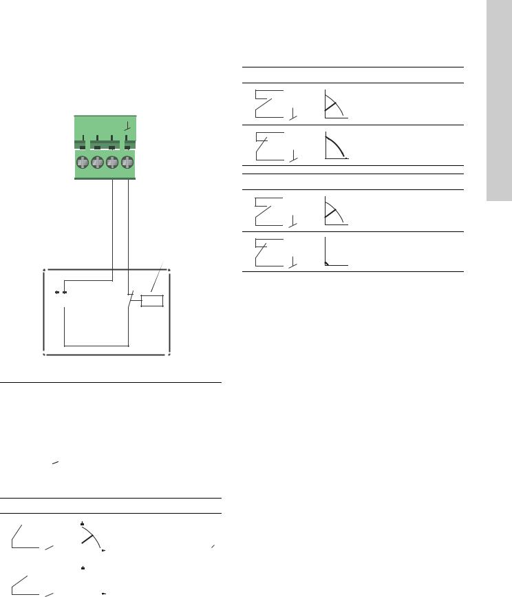
5.5.2 Digital inputs
See fig. 15, pos. 2.
The digital input can be used for external control of start/stop or forced max. or min. curve.
If no external on/off switch is connected, the jumper between terminals Start/Stop (S/S) and frame ( ) should be maintained. This connection is the factory setting.
MM
A I S/S
On/off timer

 Start/stop
TM05 3339 1212
Fig. 18 Digital input
Contact symbol |
Function |
|
|
|
|
M |
Max. curve |
|
A |
100 % speed |
|
M |
Min. curve |
|
I |
25 % speed |
|
S/S |
Start/Stop |
|
|
|
Frame connection |
|
|
|
|
|
|
External start/stop
The pump can be started or stopped via the digital input.
Start/stop
|
|
|
S/S |
H |
|
|
Normal duty |
|||
|
|
|
|
|
||||||
|
|
|
|
|
|
|
||||
|
|
|
|
|
|
|
|
|||
|
|
|
|
|
|
|
|
Note: Factory setting with |
||
|
|
|
|
|
|
|
|
Q jumper between S/S and |
|
. |
|
|
|
|
|
|
|
|
|||
|
|
|
|
|
|
|
||||
|
|
|
|
|
|
|
|
|
|
|
|
|
|
S/S |
H |
|
|
Stop |
|||
|
|
|
|
|
||||||
|
|
|
|
|
|
|
|
|||
|
|
|
|
|
|
|
||||
|
|
|
|
|
|
|
|
Q |
||
|
|
|
|
|
|
|
|
|||
|
|
|
|
|
|
|
|
|
|
|
External forced max. or min. curve
The pump can be forced to operate on the max. or min. curve via the digital input.
Max. curve
M H 
A
Normal duty
 Q
Q
M H 
A
Max. curve
 Q
Q
Min. curve
MH 
I
Normal duty
 Q
Q
M H 
I
Min. curve
 Q
Q
Select the function of the digital input on the pump control panel or with Grundfos GO Remote.
English (US)
17
(US) English
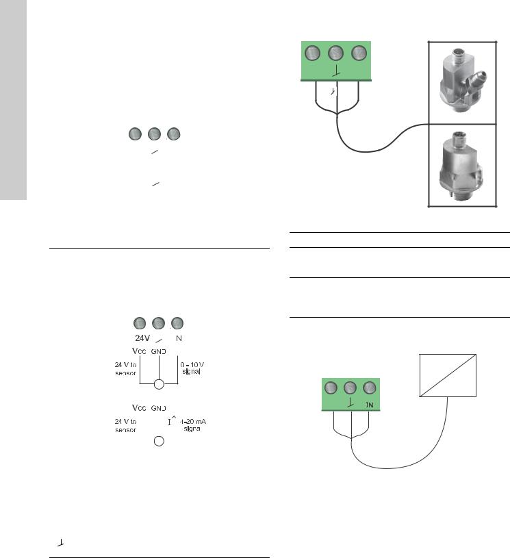
5.6 Analog input for external sensor
The analog input can be used for the connection of an external sensor for measuring temperature or pressure.
The analog input can also be used for an external signal for the control from a BMS system or similar control system.
The electrical signal for the input can be 0-10 VDC or 4-20 mA.
The selection of electrical signal (0-10 V or 4-20 mA) can be changed on the control panel or with Grundfos GO Remote.
24V |
|
|
|
IN |
|
||
|
|
|
|
||||
|
|
|
|
||||
|
|
|
|
|
|
|
1112 |
Vcc |
|
|
|
signal |
3221 |
||
|
|
|
|||||
|
|
|
|
|
|
|
TM05 |
|
|
sensor |
|
|
|||
|
|
|
|
|
|||
|
|
|
|
|
|
|
|
Fig. 19 Analog input for external sensor or control
In order to optimize the pump performance, external sensors can advantageously be used in the following cases:
Function/control mode |
Sensor type |
|||
|
|
|
|
|
Heat energy meter |
Temperature sensor |
|||
Constant temperature |
Temperature sensor |
|||
Differential pressure |
Pressure sensor |
|||
|
|
|
|
|
|
|
|
|
|
|
|
|
|
|
|
|
|
|
|
- +
Sensor
|
|
|
|
|
|
|
|
|
TM06 0882 1114 |
|
|
|
|
|
|
|
|
|
|||
|
|
|
|
|
|
|
|
|
||
|
|
|
|
|
|
|
|
|
||
|
|
|
|
|
|
|
|
|
||
|
|
|
|
|
|
|
|
|||
|
|
Sensor |
||||||||
Fig. 20 |
Wiring, analog input |
|
|
|||||||
|
|
|
|
|
|
|
|
|
|
|
PIN |
Description |
|
Load |
|||||||
|
|
|
|
|
|
|
|
|
|
|
IN |
Analog input |
150 Ω (4-20 mA signal) |
||||||||
78 kΩ (0-10 V signal) |
||||||||||
|
|
|
|
|
|
|
|
|||
24 V 24 V supply to external sensor |
|
Max. 22 mA |
||||||||
Ground for external sensor
1
24V  IN
IN
Vcc |
Signal |
2
TM05 2947 1212
Fig. 21 Examples of external sensors
Pos. Sensor type
Differential pressure transmitter,
1Grundfos type DPI V.2
1/2" connection and 4-20 mA signal. Relative pressure transmitter,
2combined pressure and temperature sensor, Grundfos type RPI/T G 1/2" connection and 4-20 mA signal.
For further details, visit WebCAPS and reference Magna3 Data booklet 98439208.
BMS
PLC
24V
TM05 2888 0612
Fig. 22 Example of external signal for the control via BMS or PLC
18
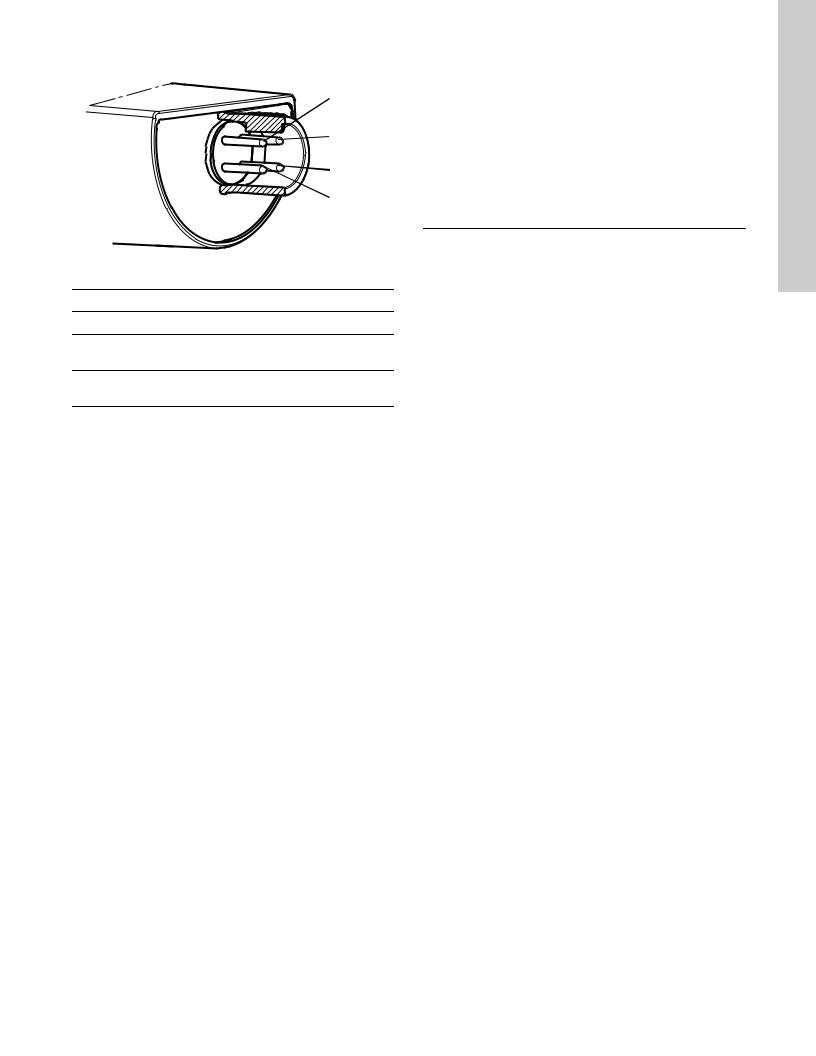
5.7 Electrical connection for external sensor
|
|
|
|
2 |
|
|
|
|
|
1 |
|
|
|
|
|
4 |
|
|
|
|
|
7156TM041610 |
|
|
|
|
|
3 |
|
Fig. 23 Example electrical connections for external sensor |
|||||
PIN |
1 |
2 |
3 |
4 |
|
Wire color |
Brown |
Grey |
Blue |
Black |
|
Output |
+ |
not used |
- |
not used |
|
4 to 20 mA |
|||||
|
|
|
|
||
Output |
+ |
Pressure |
-* |
Temperature |
|
2 x 0 to 10 V |
signal |
signal |
|||
|
|
||||
*Common ground for both pressure and temperature signal.
*Power supply (screened cable): SELV or PELV.
5.8 Priority of settings
The external forced-control signals will influence the settings available on the pump control panel or with Grundfos GO Remote. However, the pump can always be set to max. curve duty or to stop on the pump control panel or with Grundfos GO Remote.
If two or more functions are enabled at the same time, the pump will operate according to the setting with the highest priority.
The priority of the settings is as shown in the table below.
Example: If the pump has been forced to stop via an external signal, the pump control panel or Grundfos GO Remote can only set the pump to max. curve.
|
|
Possible settings |
|
|
|
|
|
|
|
Priority |
Pump control |
External |
|
|
panel or |
Bus signal |
|||
|
||||
|
Grundfos GO |
signals |
||
|
|
|||
|
Remote |
|
|
|
|
|
|
|
|
1 |
Stop |
|
|
|
2 |
Max. curve |
|
|
|
3 |
|
Stop |
|
|
4 |
|
|
Stop |
|
5 |
|
|
Max. curve |
|
6 |
|
|
Min. curve |
|
7 |
|
|
Start |
|
8 |
|
Max. curve |
|
|
9 |
Min. curve |
|
|
|
10 |
|
Min. curve |
|
|
11 |
Start |
|
|
As illustrated in the table, the pump does not react to external signals (max. curve and min. curve) when it is controlled via bus.
For further details, please contact Grundfos.
English (US)
19
English |
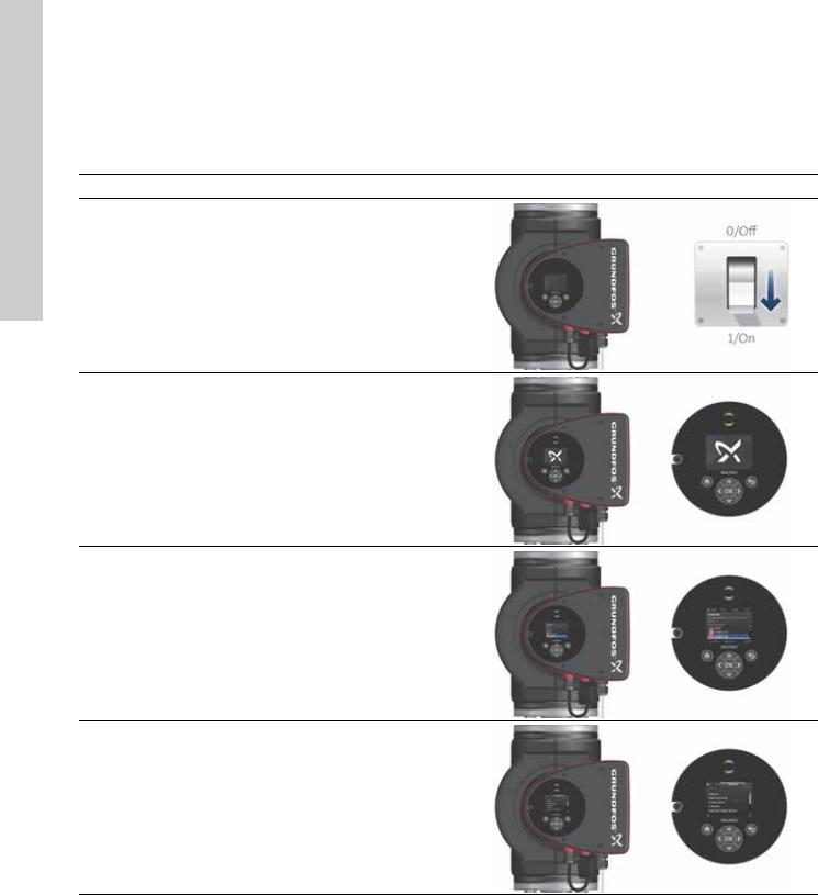
6. First start-up |
|
|
Do not start the pump until the system has been filled with liquid |
|
||
|
|
||
|
and vented. Furthermore, the required minimum inlet pressure |
|
|
(US) |
must be available at the pump inlet. See section 19. Technical |
|
|
data. |
|
|
|
|
|
|
|
|
The system cannot be vented through the pump. The pump is |
|
|
|
self-venting. |
|
|
|
Step |
Action |
Illustration |
Switch on the power supply to the pump.
1Note: When switched on, the pump will start in AUTOADAPT after approx. 5 seconds.
Pump display at first start-up.
2After a few seconds, the pump display will change to the start-up guide.
The start-up guide will guide you through the general settings of the pump, such as language, date and time.
3If the buttons on the pump control panel are not touched for 15 minutes, the display will go into sleep mode.
When a button is touched, the "Home" display will appear.
When the general settings have been made, select the
4desired control mode or let the pump run in AUTOADAPT. For additional settings, see section 7. Settings.
TM05 2884 0612
TM05 2885 0612
TM05 2886 0612
TM05 2887 0612
20
7. Settings
7.1 Overview of settings
All settings can be made on the pump control panel or with Grundfos GO Remote.
Menu |
Submenu |
Further information |
|
|
|
|
|
Setpoint |
|
|
See section 13.1 Setpoint. |
|
|
|
|
Operating mode |
|
|
See section 13.2 Operating mode. |
|
• |
Normal |
|
|
• |
Stop |
|
|
• |
Min. |
|
|
• |
Max. |
|
Control mode |
|
|
See section 13.3 Control mode. |
|
• |
AUTOADAPT |
See section 13.3.1 AUTOADAPT. |
|
• |
FLOWADAPT |
See section 13.3.2 FLOWADAPT. |
|
• |
Prop. press. |
See section 13.3.3 Proportional pressure. |
|
• |
Const. press. |
See section 13.3.4 Constant pressure. |
|
• |
Const. temp. |
See section 13.3.5 Constant temperature. |
|
• |
Differential temperature |
See section 13.3.6 Differential temperature. |
|
• |
Constant curve |
See section 13.3.7 Constant curve. |
FLOWLIMIT |
|
|
See section 13.4 FLOWLIMIT. |
|
• |
Set FLOWLIMIT |
|
Automatic Night Setback |
|
|
See section 13.5 Automatic Night Setback. |
|
• |
Not active |
|
|
• |
Active |
|
Relay outputs |
|
|
See section 13.6 Relay outputs. |
|
• |
Relay output 1 |
|
|
• |
Relay output 2 |
|
Setpoint influence |
|
|
See section 13.7 Setpoint influence. |
|
• |
External setpoint function |
See section 13.7.1 External setpoint function. |
|
• |
Temperature influence |
See section 13.7.2 Temperature influence. |
Bus communication |
|
|
See section 13.8 Bus communication. |
|
• |
Pump number |
See section 13.8.1 Pump number. |
General settings |
|
|
See section 13.9 General settings. |
|
• |
Language |
See section 13.9.1 Language. |
|
• |
Set date and time |
See section 13.9.2 Set date and time. |
|
• |
Units |
See section 13.9.3 Units. |
|
• |
Enable/disable settings |
See section 13.9.4 Enable/disable settings. |
|
• |
Delete history |
See section 13.9.5 Delete history. |
|
• |
Define Home display |
See section 13.9.6 Define Home display. |
|
• |
Display brightness |
See section 13.9.7 Display brightness. |
|
• |
Return to factory settings |
See section 13.9.8 Return to factory settings. |
|
• |
Run start-up guide |
See section 13.9.9 Run start-up guide. |
English (US)
21

(US) English
8. Menu overview
Status |
Settings |
Assist |
Operating status |
Setpoint |
Assisted pump setup |
Operating mode, from |
Operating mode |
Setting of pump |
Control mode |
Control mode |
Setting of date and time |
Pump performance |
FLOWLIMIT |
Date format, date and time |
Max. curve and duty point |
Enable FLOWLIMIT function |
Date only |
Resulting setpoint |
Set FLOWLIMIT |
Time only |
Liquid temperature |
Automatic Night Setback |
Multi-pump setup |
Speed |
Relay outputs |
Setup, analog input |
Operating hours |
Relay output 1 |
Description of control mode |
Power and energy consumption |
Relay output 2 |
AUTOADAPT |
Power consumption |
Not active |
FLOWADAPT |
Energy consumption |
Ready |
Prop. press. |
Warning and alarm |
Alarm |
Const. press. |
Actual warning or alarm |
Operation |
Const. temp. |
Warning log |
Setpoint influence |
Differential temperature |
Warning log 1 to 5 |
External setpoint function |
Constant curve |
Alarm log |
Temperature influence |
Assisted fault advice |
Alarm log 1 to 5 |
Bus communication |
Blocked pump |
Heat energy meter |
Pump number |
Pump communication fault |
Heat power |
General settings |
Internal fault |
Heat energy |
Language |
Internal sensor fault |
Flow rate |
Set date and time |
Dry running |
Volume |
Select date format |
Forced pumping |
Hours counter |
Set date |
Undervoltage |
Temperature 1 |
Select time format |
Overvoltage |
Temperature 2 |
Set time |
External sensor fault |
Differential temp. |
Units |
|
Work log |
SI or US units |
|
Operating hours |
Customized units |
|
Trend data |
Pressure |
|
Duty point over time |
Differential pressure |
|
3D showing (Q, H, t) |
Head |
|
3D showing (Q, T, t) |
Level |
|
3D showing (Q, P, t) |
Flow rate |
|
3D showing (T, P, t) |
Volume |
|
Fitted modules |
Temperature |
|
Date and time |
Differential temp. |
|
Date |
Power |
|
Time |
Energy |
|
Pump identification |
Enable/disable settings |
|
Multi-pump system |
Delete history |
|
Operating status |
Delete work log |
|
Operating mode, from |
Delete heat energy data |
|
Control mode |
Delete energy consumption |
|
System performance |
Define Home display |
|
Duty point |
Select Home display type |
|
Resulting setpoint |
List of data |
|
System identification |
Graphical illustration |
|
Power and energy consumption |
Define Home display contents |
|
Power consumption |
List of data |
|
Energy consumption |
Graphical illustration |
|
Other pump 1, multi-pump sys. |
Display brightness |
|
|
Brightness |
|
|
Return to factory settings |
|
|
Run start-up guide |
|
22
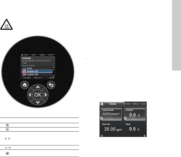
9. Control panel
Warning
At high liquid temperatures, the pump housing may be very hot. In that case, only touch the control panel.
TM05 7642 1313
Fig. 24 Control panel
Button Function
Goes to the "Home" menu.
Returns to the previous action.
Navigates between main menus, displays and digits.
When the menu is changed, the display will always show the top display of the new menu.
Navigates between submenus.
Saves changed values, resets alarms and expands the value field.
10. Menu structure
The pump incorporates a start-up guide which is started at the first start-up. After the start-up guide, the four main menus will appear in the display. See section 6. First start-up.
1. Home
This menu shows up to four user-defined parameters with shortcuts or a graphical illustration of a Q/H performance curve. See section 11. "Home" menu.
2. Status
This menu shows the status of the pump and system as well as warnings and alarms. See section 12. "Status" menu.
Note |
No settings can be made in this menu. |
3. Settings
This menu gives access to all setting parameters. A detailed setting of the pump can be made in this menu.
See section 13. "Settings" menu.
4. Assist
This menu enables assisted pump setup, provides a short description of the control modes and offers fault advice.
See section 14. "Assist" menu.
11. "Home" menu
TM05 7929 1613
Navigation
Home
Press  to go to the "Home" menu.
"Home" menu (factory setting)
•Shortcut to control mode settings
•Shortcut to setpoint settings
•Flow rate
•Head.
Navigate in the display with  or
or  and change between the two shortcuts with
  or
or  .
.
The "Home" display can be defined by the user. See section 13.9.6 Define Home display.
English (US)
23
(US) English
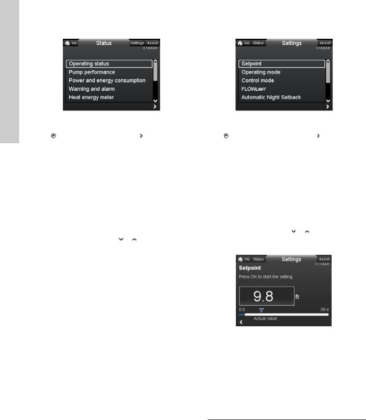
12. "Status" menu |
13. "Settings" menu |
|
2.1.0.0.0.0 Status |
|
3.1.0.0.0.0 Settings |
Navigation |
Navigation |
||
Home > Status |
Home > Settings |
||
Press and go to the "Status" menu with . |
Press and go to the "Settings" menu with . |
||
"Status" menu |
"Settings" menu |
||
This menu offers the following status information: |
This menu offers the following setting options: |
||
• |
Operating status |
• |
Setpoint |
• |
Pump performance |
• |
Operating mode |
• Power and energy consumption |
• |
Control mode |
|
• |
Warning and alarm |
• |
FLOWLIMIT |
• |
Heat energy meter |
• |
Automatic Night Setback |
• |
Work log |
• |
Relay outputs |
• |
Fitted modules |
• |
Setpoint influence |
• |
Date and time |
• |
Bus communication |
• |
Pump identification |
• |
General settings. |
• |
Multi-pump system. |
Navigate between submenus with or . |
|
Navigate between submenus with or . |
13.1 Setpoint |
||
|
|
||
TM05 7925 1613
Navigation
Home > Settings > Setpoint
Setpoint
Set the setpoint so that it matches the system.
Setting:
1.Press [OK] to start the setting.
2.Select digit with  and
and  and adjust with
  or
or  .
.
3.Press [OK] to save.
A too high setting may result in noise in the system whereas a too low setting may result in insufficient heating or cooling in the system.
Control mode |
Measuring unit |
|
|
Proportional pressure |
m, ft |
Constant pressure |
m, ft |
Constant temperature |
°C, °F, K |
Constant curve |
% |
24
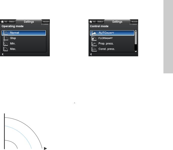
13.2 Operating mode |
13.3 Control mode |
3.1.2.0.0.0 Operating mode
Navigation
Home > Settings > Operating mode
Operating mode
•Normal (control mode)
•Stop
•Min. (min. curve)
•Max. (max. curve). Setting:
1. Select operating mode with  or
or  .
.
2. Press [OK] to save.
The pump can be set to operate according to the max. or min. curve, like an uncontrolled pump. See fig. 25.
H 
Max.
Min. |
5111 |
||
TM05 2446 |
|||
|
Q |
||
|
|||
Fig. 25 Max. and min. curves
•Normal: The pump runs according to the selected control mode.
•Stop: The pump stops.
•Min.: The min. curve mode can be used in periods in which a minimum flow is required.
This operating mode is for instance suitable for manual night setback if Automatic Night Setback is not desired.
•Max.: The max. curve mode can be used in periods in which a maximum flow is required.
This operating mode is for instance suitable for hot-water priority.
3.1.3.0.0.0 Control mode
Navigation
Home > Settings > Control mode
Control mode
•AUTOADAPT
•FLOWADAPT
•Prop. press. (proportional pressure)
•Const. press. (constant pressure)
•Const. temp.(constant temperature)
•Constant curve.
|
The operating mode must be set to "Normal" |
|
Note |
||
before a control mode can be enabled. |
||
|
Setting:
1. Select control mode with  or
or  .
.
2. Press [OK] to enable.
The setpoint for all control modes, except AUTOADAPT and FLOWADAPT, can be changed in the "Setpoint" submenu under "Settings" when the desired control mode has been selected.
All control modes, except "Constant curve", can be combined with Automatic Night Setback. See section 13.5 Automatic Night Setback.
The FLOWLIMIT function can also be combined with the last five control modes mentioned above. See section 13.4 FLOWLIMIT.
English (US)
25
(US) English
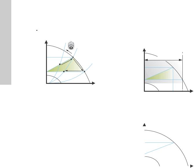
13.3.1 AUTOADAPT
The AUTOADAPT control mode continuously adapts the pump performance according to the actual system characteristic.
Note |
Manual setting of the setpoint is not possible. |
|
H |
|
|
|
|
Hfac |
Hset1 |
|
|
|
A1 |
|
|
|
Hauto_min |
A2 |
Hset2 |
1312 |
|
|
A3 |
TM05 2452 |
||
|
|
|
Q |
|
Fig. 26 |
AUTOADAPT |
|
|
|
When the AUTOADAPT control mode has been enabled, the pump will start with the factory setting, Hfac = Hset1, corresponding to
approx. 55 % of its maximum head, and then adjust its performance to A1. See fig. 26.
When the pump registers a lower head on the max. curve, A2, the AUTOADAPT function will automatically select a correspondingly lower control curve, Hset2. If the valves in the system close, the pump will adjust its performance to A3.
A1: Original duty point.
A2: Lower registered head on the max. curve.
A3: New duty point after AUTOADAPT control. Hset1: Original setpoint setting.
Hset2: New setpoint after AUTOADAPT control. Hfac.: MAGNA3 xx-60: 11.4 ft (3.5 m)
MAGNA3 xx-80: 14.7 ft (4.5 m) MAGNA3 xx-100: 18 ft (5.5 m) MAGNA3 xx-120: 21.3 ft (6.5 m) MAGNA3 xx-150: 26.2 ft (8.0 m) MAGNA3 xx-180: 31.1 ft (9.5 m).
Hauto_min: A fixed value of 4.9 ft (1.5 m).
The AUTOADAPT control mode is a form of proportional-pressure control where the control curves have a fixed origin, Hauto_min.
The AUTOADAPT control mode has been developed specifically for heating systems and is not recommended for air-conditioning
and cooling systems.
To reset AUTOADAPT, see section 13.9.8 Return to factory settings.
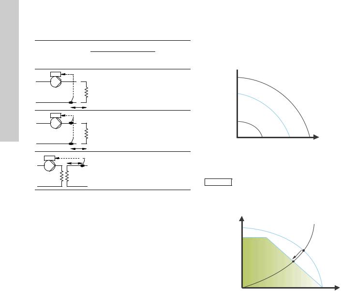
13.3.2 FLOWADAPT
When FLOWADAPT is selected, the pump will run AUTOADAPT and ensure that the flow never exceeds the entered FLOWLIMIT value.
The setting range for the FLOWLIMIT is 25 to 90 % of the Qmax of the pump.
The factory setting of the FLOWLIMIT is the flow where the AUTOADAPT factory setting meets the max. curve. See fig. 27.
|
H |
90 % Qmax |
|
|
Setting range |
|
|
|
Hfac |
|
|
Hauto_min |
|
12123334 |
|
|
|
||
|
Qfac |
Q |
TM05 |
|
|
||
Fig. 27 |
FLOWADAPT |
|
|
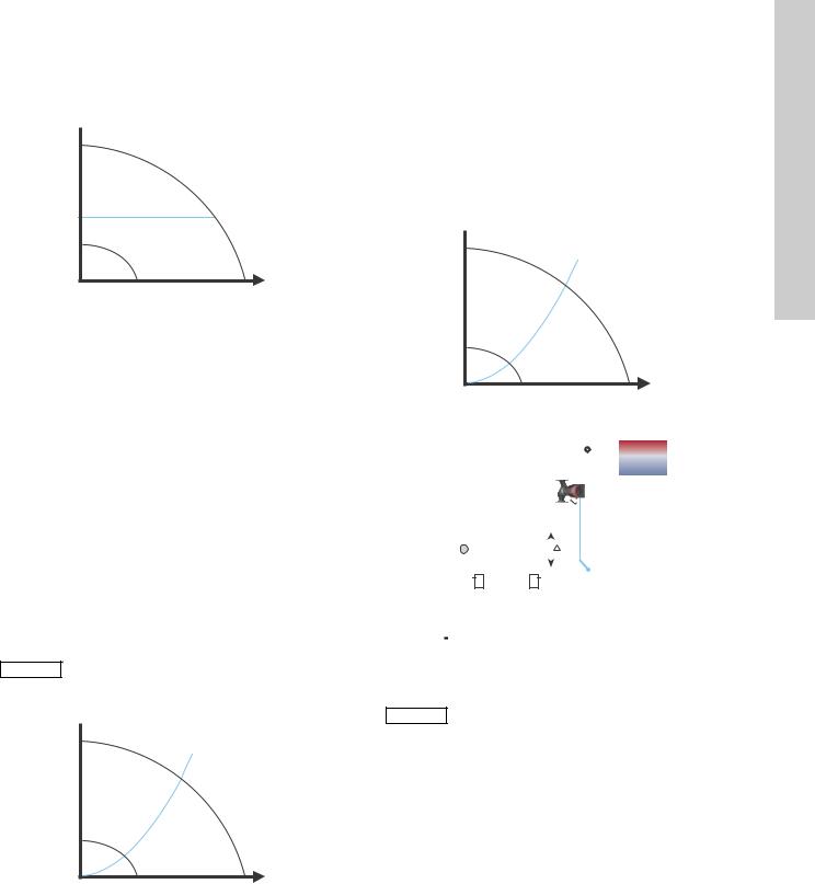
13.3.3 Proportional pressure
The pump head is reduced at decreasing water demand and increased at rising water demand. See fig. 28.
|
H |
|
|
|
|
|
|
|
|
||||
|
Hset |
|
|
|
|
|
Hset |
|
|
|
1212 |
||
|
|
|
2448 |
|||
|
2 |
|
|
|
|
|
|
|
|
|
|
Q |
TM05 |
|
|
|
|
|
||
Fig. 28 Proportional pressure
26
13.3.4 Constant pressure
The pump maintains a constant pressure, irrespective of water demand. See fig. 29.
H 
Q |
TM05 2449 0312 |
Fig. 29 Constant pressure
13.3.5 Constant temperature
This control mode ensures a constant temperature.
Constant temperature is a comfort control mode that can be used in domestic hot-water systems to control the flow to maintain a fixed temperature in the system. See fig. 30. When this control mode is used, no balancing valves must be installed in the system.
If the pump is installed in the return pipe of the system, the internal temperature sensor can be used. In this case, the pump must be installed as close as possible to the consumer (radiator, heat exchanger, etc.).
If the pump is installed in the flow pipe, an external temperature sensor must be installed in the return pipe of the system.
The sensor must be installed as close as possible to the consumer (radiator, heat exchanger, etc.).
The constant-temperature control mode also reduces the risk of bacterial growth (for example Legionella) in the system.
It is possible to set the sensor range:
•min. +14 °F (-10 °C)
•max. +266 °F (+130 °C).
To ensure that the pump is able to control, we Note recommend to set the sensor range between
+3 °F and +257 °F (-5 and +125 °C).
H 
Q |
TM05 2451 5111 |
Fig. 30 Constant temperature
13.3.6 Differential temperature
This control mode ensures a constant differential temperature drop across a heating system.
The pump should be installed in the flow pipe so the built-in sensor measures the liquid temperature going out to the load. An external temperature sensor must be installed in the system to measure the liquid temperature returning from the heating load. In this mode, the pump will maintain a constant temperature. See figs 31 and 32, differential between the pump and the external sensor.
H 
t
Q |
TM05 2451 5111 |
Fig. 31 Differential temperature
|
|
|
|
|
|
|
|
|
|
|
|
|
|
|
|
|
|
|
|
|
|
|
|
|
|
|
|
|
|
|
|
|
|
|
|
|
|
|
|
|
|
|
|
|
|
|
|
|
|
|
|
|
|
|
|
|
|
|
|
|
|
|
|
|
|
|
|
|
|
|
|
2113 |
|||||||||||
|
|
|
|
|
|
|
|
|
|
|||||||||||
|
|
|
|
|
|
|
|
|
|
|||||||||||
|
|
|
|
|
|
|
|
t |
|
|
|
|
|
|
|
|
|
|
TM05 8236 |
|
Fig. 32 |
Differential temperature |
|||||||||||||||||||
|
|
Changing Kp and Ti values are only possible with |
||||||||||||||||||
Note |
|
|||||||||||||||||||
|
|
Grundfos GO. |
||||||||||||||||||
|
|
|||||||||||||||||||
Changing the Kp and Ti values will affect all control modes. If the control mode is to be
Note changed back to another mode you must set the Kp and Ti values back to default values. For all
other modes the default values are Kp = 0.5, Ti = 0.5.
English (US)
27
(US) English
See table, fig. 33.
The table shows the suggested controller settings:
|
|
Kp |
|
System/application |
Heating |
Cooling |
Ti |
|
system1) |
system2) |
|
t |
0.5 |
- 0.5 |
10 + 5L2 |
|
|
|
|
L2 [m] |
|
|
|
t |
|
-0.5 |
10 + 5L2 |
L2 [m] |
|
|
|
L2 [m] |
|
|
|
t |
0.5 |
- 0.5 |
30 + 5L2 |
Fig. 33 Suggested controller settings
1)Heating systems are systems in which an increase in pump performance will result in a rise in temperature at the sensor.
2)Cooling systems are systems in which an increase in pump performance will result in a drop in temperature at the sensor.
L2 = Distance in [m] between heat exchanger and sensor.
Proceed as follows:
1.Increase the gain (Kp) until the motor becomes unstable. Instability can be seen by observing if the measured value starts to fluctuate. Furthermore, instability is audible as the motor starts hunting up and down.
Some systems, such as temperature controls, are slow-reacting, meaning that it may be several minutes before the motor becomes unstable.
2.Set the gain (Kp) to half the value of the value which made the motor unstable. This is the correct setting of the gain.
3.Reduce the integral time (Ti) until the motor becomes unstable.
4.Set the integral time (Ti) to twice the value which made the motor unstable. This is the correct setting of the integral time.
General rules of thumb:
•If the controller is too slow-reacting, increase Kp.
•If the controller is hunting or unstable, dampen the system by reducing Kp or increasing Ti.
13.3.7 Constant curve
The pump can be set to operate according to a constant curve, like an uncontrolled pump. See fig. 34.
The desired speed can be set in % of maximum speed in the range from 25 to 100 %.
H 
Q |
TM05 2446 0312 |
Fig. 34 Constant curve
Depending on the system characteristic and the duty point, the 100 % setting may be slightly smaller than the pump's actual max. curve even
Note though the display shows 100 %. This is due to power and pressure limitations built into the pump. The deviation varies according to pump type and pressure loss in the pipes.
H [%]
100 %
Limited max. curve
Max. curve |
|
Actual duty point |
TM05 3041 1212 |
Q [m3/h] |
Fig. 35 Power and pressure limitations influencing the max. curve
28
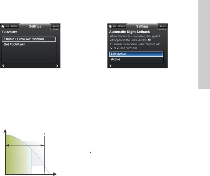
13.4 FLOWLIMIT
3.1.5.0.0.0 FLOWLIMIT
Navigation
Home > Settings > FLOWLIMIT
FLOWLIMIT
•Enable FLOWLIMIT function
•Set FLOWLIMIT.
Setting:
1. To enable the function, select "Active" with  or
or  and press [OK].
2. To set the FLOWLIMIT, press [OK] to start the setting. 3. Select digit with  and
and  and adjust with
  or
or  .
.
4. Press [OK] to save.
H |
90 % Qmax |
|
|
Setting range |
|
|
|
|
Q |
2445 1212 |
|
Qlimit |
TM05 |
||
|
Fig. 36 FLOWLIMIT
The FLOWLIMIT function can be combined with the following control modes:
•Prop. press.
•Const. press.
•Const. temp.
•Constant curve.
A flow-limiting function ensures that the flow never exceeds the entered FLOWLIMIT value.
The setting range for FLOWLIMIT is 25 to 90 % of the Qmax of the pump.
The factory setting of the FLOWLIMIT is the flow where the AUTOADAPT factory setting meets the max. curve. See fig. 27.
13.5 Automatic Night Setback |
English (US) |
Night Setback |
|
3.1.6.0.0.0 Automatic |
|
Navigation
Home > Settings > Automatic Night Setback
Automatic Night Setback
To enable the function, select "Active" with  or
or  and press [OK].
Once Automatic Night Setback has been enabled, the pump automatically changes between normal duty and night setback (duty at low performance).
Changeover between normal duty and night setback depends on the flow-pipe temperature.
The pump automatically changes over to night setback when the built-in sensor registers a flow-pipe temperature drop of more than +18 to +27 °F (-8 to -3 °C) within approx. two hours.
The temperature drop must be at least 0.18 °F/min (0.1 °C/min).
Changeover to normal duty takes place without a time lag when the temperature has increased by approx. +18 °F (-8 °C).
|
Automatic Night Setback cannot be enabled |
|
Note |
||
when the pump is in constant-curve mode. |
||
|
29
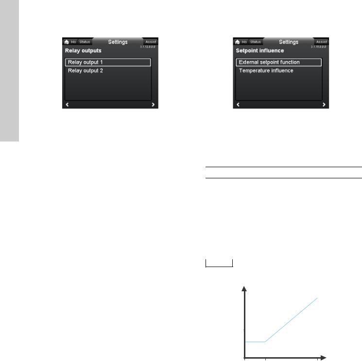
(US) English
13.6 Relay outputs |
13.7 Setpoint influence |
3.1.12.0.0.0 Relay outputs
Navigation
Home > Settings > Relay outputs
Relay outputs
•Relay output 1
•Relay output 2.
The relay outputs can be set to the following:
•Not active
•Ready
•Alarm
•Operation.
The pump incorporates two signal relays, terminals 1, 2 and 3, for a potential-free alarm signal, ready signal and operating signal. For further information, see section 5.5.1 Relay outputs.
Set the function of the signal relays, alarm signal (factory setting), ready signal and operating signal, on the pump control panel.
The output, terminals 1, 2 and 3, is electrically separated from the rest of the controller.
The signal relay is operated as follows:
•Not active
The signal relay is deactivated.
•Ready
The signal relay is active when the pump is running or has been set to stop, but is ready to run.
•Alarm
The signal relay is activated together with the red indicator light on the pump.
•Operation
The signal relay is activated together with the green indicator light on the pump.
3.1.15.0.0.0 Setpoint influence
Navigation
Home > Settings > Setpoint influence
Setpoint influence
•External setpoint function
•Temperature influence.
13.7.1 External setpoint function
Range
4-20 mA |
[0-100 %] |
|
0-10 V |
[0-100 %] |
|
Control |
|
|
|
|
|
0-20 % |
(e.g. 0-2 V) |
Setpoint = Min. |
20-100 % |
(e.g. 2-10 V) |
Setpoint = Min. ↔ setpoint |
The external setpoint function is an external 0-10 V or 4-20 mA signal that will control the pump speed in a range from 0 to 100 % in a linear function. See fig. 37.
|
Before the "External setpoint function" can be |
|
Note |
enabled, the analog input must be set to "External |
|
setpoint influence" via the "Assist" menu. |
||
|
See section 5.6 Analog input for external sensor.
|
rpm |
|
|
|
|
|
Max. |
|
|
|
|
|
Min. |
|
|
|
1212 |
|
0 |
2 |
10 |
|
3219 |
|
V |
TM05 |
|||
|
|
|
|
|
|
Fig. 37 |
External setpoint function, 0-10 V |
|
|
|
|
30
Loading...