


 Loading...
GRUNDFOS INSTRUCTIONS
MAGNA3
Installation and operating instructions

(US) English
English (US) Installation and operating instructions
Original installation and operating instructions.
CONTENTS
1.Limited warranty
2.Symbols used in this document
3.General information
3.1Applications
3.2Pumped liquids
3.3Operating conditions
3.4Frost protection
3.5Insulating shells
3.6Non-return valve
3.7Nameplate
3.8Radio communication
3.9Tools
4.Mechanical installation
4.1Installing the pump
4.2Positioning
4.3Control box positions
4.4Changing the control box position
5.Electrical installation
5.1Supply voltage
5.2Connection to the power supply
5.3Connection diagram
5.4Connection to external controllers
5.5Input/output communication
5.6Priority of settings
6.First start-up
7.Settings
7.1Overview of settings
8.Menu overview
9.Control panel
10.Menu structure
11."Home" menu
12."Status" menu
13."Settings" menu
13.1Setpoint
13.2Operating mode
13.3Control mode
13.4FLOWLIMIT
13.5Automatic Night Setback
13.6Relay outputs
13.7Setpoint influence
13.8Bus communication
13.9General settings
14."Assist" menu
14.1Assisted pump setup
14.2Setting of date and time
14.3Multi-pump setup
14.4Setup, analog input
14.5Description of control mode
14.6Assisted fault advice
14.7Wireless GENIair
14.8Multi-pump function
15.Selection of control mode
16.Fault finding
16.1Grundfos Eye operating indications
16.2Signalling communication with remote control
16.3Fault finding
17.Sensor
17.1Sensor specifications
|
18. |
Accessories |
34 |
|
|
18.1 |
Grundfos GO Remote |
34 |
|
|
18.2 |
Communication |
34 |
|
Page |
18.3 |
Fitting the CIM module |
35 |
|
2 |
19. |
Technical data |
36 |
|
3 |
20. |
Disposal |
36 |
|
3 |
|
|
|
|
3 |
|
Warning |
|
|
3 |
|
Prior to installation, read these installation and |
|
|
4 |
|
|
||
|
operating instructions. Installation and operation |
|||
4 |
|
|||
|
must comply with local regulations and accepted |
|||
4 |
|
|||
|
codes of good practice. |
|
||
4 |
|
|
|
|
5 |
|
Warning |
|
|
6 |
|
The use of this product requires experience with |
||
6 |
|
and knowledge of the product. |
|
|
6 |
|
Persons with reduced physical, sensory or |
|
|
6 |
|
mental capabilities must not use this product, |
|
|
7 |
|
unless they are under supervision or have been |
||
7 |
|
instructed in the use of the product by a person |
||
8 |
|
responsible for their safety. |
|
|
9 |
|
Children must not use or play with this product. |
||
|
|
|
||
9 |
1. Limited warranty |
|
||
9 |
|
|||
11 |
Products manufactured by GRUNDFOS PUMPS CORPORATION |
|||
11 |
(Grundfos) are warranted to the original user only to be free of |
|
||
11 |
defects in material and workmanship for a period of 24 months |
|
||
14 |
from date of installation, but not more than 30 months from date |
|||
15 |
of manufacture. Grundfos' liability under this warranty shall be |
|
||
16 |
limited to repairing or replacing at Grundfos' option, without |
|
||
charge, F.O.B. Grundfos' factory or authorized service station, |
|
|||
16 |
|
|||
any product of Grundfos' manufacture. Grundfos will not be liable |
||||
17 |
||||
for any costs of removal, installation, transportation, or any other |
||||
18 |
||||
charges which may arise in connection with a warranty claim. |
|
|||
18 |
Products which are sold but not manufactured by Grundfos are |
|
||
18 |
subject to the warranty provided by the manufacturer of said |
|
||
18 |
products and not by Grundfos' warranty. Grundfos will not be |
|
||
liable for damage or wear to products caused by abnormal |
|
|||
19 |
|
|||
operating conditions, accident, abuse, misuse, unauthorized |
|
|||
19 |
|
|||
alteration or repair, or if the product was not installed in |
|
|||
19 |
|
|||
accordance with Grundfos' printed installation and operating |
|
|||
20 |
|
|||
instructions. |
|
|||
23 |
|
|||
To obtain service under this warranty, the defective product must |
||||
23 |
||||
be returned to the distributor or dealer of Grundfos' products from |
||||
23 |
||||
which it was purchased together with proof of purchase and |
|
|||
24 |
|
|||
installation date, failure date, and supporting installation data. |
|
|||
25 |
|
|||
Unless otherwise provided, the distributor or dealer will contact |
|
|||
25 |
|
|||
Grundfos or an authorized service station for instructions. Any |
|
|||
27 |
defective product to be returned to Grundfos or a service station |
|||
27 |
must be sent freight prepaid; documentation supporting the war- |
|||
27 |
ranty claim and/or a Return Material Authorization must be |
|
||
27 |
included if so instructed. |
|
||
27 |
GRUNDFOS WILL NOT BE LIABLE FOR ANY |
|
||
27 |
|
|||
INCIDENTAL OR CONSEQUENTIAL DAMAGES, LOSSES, OR |
||||
27 |
||||
EXPENSES ARISING FROM INSTALLATION, USE, OR ANY |
|
|||
27 |
OTHER CAUSES. THERE ARE NO EXPRESS OR IMPLIED |
|
||
28 |
WARRANTIES, INCLUDING MERCHANTABILITY OR FITNESS |
|||
29 |
FOR A PARTICULAR PURPOSE, WHICH EXTEND BEYOND |
|
||
31 |
THOSE WARRANTIES DESCRIBED OR REFERRED TO |
|
||
31 |
ABOVE. |
|
|
|
31 |
Some jurisdictions do not allow the exclusion or |
|
||
32 |
limitation of incidental or consequential damages and some juris- |
|||
33 |
dictions do not allow limit actions on how long implied warranties |
|||
may last. Therefore, the above limitations or exclusions may not |
||||
33 |
||||
2
apply to you. This warranty gives you specific legal rights and you may also have other rights which vary from jurisdiction to jurisdiction.
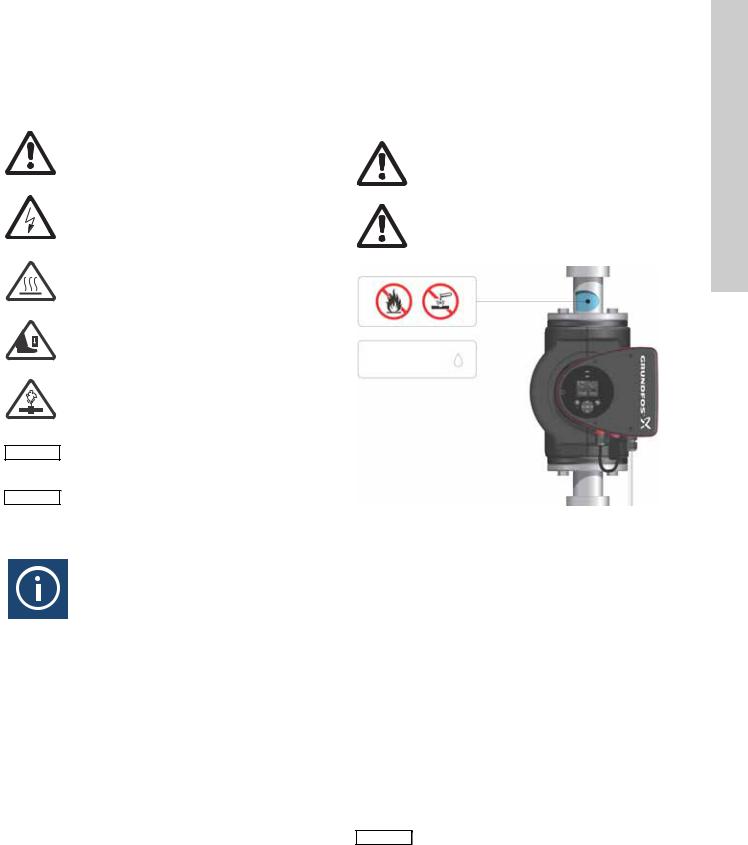
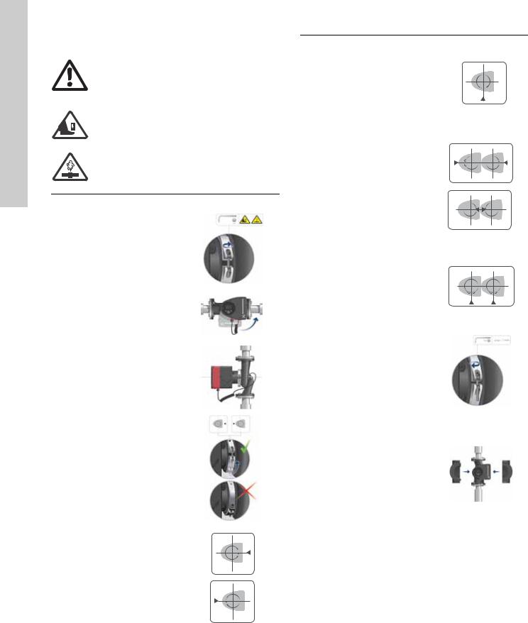
2. Symbols used in this document
Warning
If these safety instructions are not observed, it may result in personal injury.
Warning
If these instructions are not observed, it may lead to electric shock with consequent risk of serious personal injury or death.
Warning
The surface of the product may be so hot that it may cause burns or personal injury.
Warning
Risk of dropping objects which may cause personal injury.
Warning
Escaping vapor involves the risk of personal injury.
If these safety instructions are not observed,
Caution it may result in malfunction or damage to the |
||
|
equipment. |
|
Note |
Notes or instructions that make the job easier |
|
and ensure safe operation. |
||
|
||
3. General information
The Grundfos MAGNA3 is a complete range of circulator pumps with integrated controller enabling adjustment of pump performance to the actual system requirements. In many systems, this will reduce the power consumption considerably, reduce noise from thermostatic radiator valves and similar fittings and improve the control of the system.
The desired head can be set on the pump control panel.
3.1 Applications
The Grundfos MAGNA3 is designed for circulating liquids in the following systems:
•heating systems
•domestic hot-water systems
•air-conditioning and cooling systems.
The pump can also be used in the following systems:
•ground source heat pump systems
•solar-heating systems.
3.2 Pumped liquids
The pump is suitable for thin, clean, non-aggressive and non-explosive liquids, not containing solid particles or fibers that may attack the pump mechanically or chemically.
In heating systems, the water should meet the requirements of accepted standards on water quality in heating systems.
In domestic hot-water systems, we recommend to use MAGNA3 pumps only for water with a degree of hardness lower than approx. 14 °dH.
In domestic hot-water systems, we recommend to keep the liquid temperature below 150 °F (+65 °C) to eliminate the risk of lime precipitation.
Warning
Do not use the pump for flammable liquids, such as diesel oil and gasoline.
Warning
Do not use the pump for aggressive liquids, such as acids and sea water.
Max. 95 % RH
Enclosure Type 2
TM05 2857 0612
Fig. 1 Pumped liquids
3.2.1 Glycol
The pump can be used for pumping water/ethylene glycol mixtures up to 50 %.
Maximum viscosity: 50 cSt ~ 50 % water / 50 % ethylene glycol mixture at +14 °F (-10 °C).
The pump has a power-limiting function that protects against overload.
The pumping of glycol mixtures will affect the max. curve and reduce the performance, depending on the water/ethylene glycol mixture and the liquid temperature.
To prevent the ethylene glycol mixture from degrading, avoid temperatures exceeding the rated liquid temperature and minimize the operating time at high temperatures.
It is important to clean and flush the system before the ethylene glycol mixture is added.
To prevent corrosion or lime precipitation, check and maintain the ethylene glycol mixture regularly. If further dilution of the supplied ethylene glycol is required, follow the glycol supplier's instructions.
Additives with a density and/or kinematic Note viscosity higher than those/that of water will
reduce the hydraulic performance.
English (US)
3
(US) English
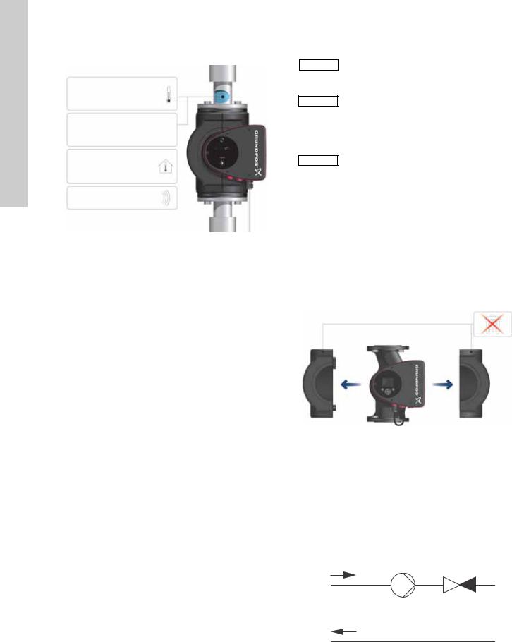
3.3 Operating conditions
|
Min./Max. |
|
1 +14 °F – 230 °F |
|
|
|
(-10 °C – +110 °C) |
|
2 |
175 psi (12 bar) |
|
3 |
+32 to +104 °F |
|
(0 to +40 °C) |
|
|
4 |
<43 dB(A) |
1413 |
|
|
TM05 7662 |
Fig. 2 Operating conditions
3.3.1Liquid temperature
See fig. 2, pos. 1.
Continuously: +14 °F to +230 °F (-10 °C to +110 °C). Domestic hot-water systems:
• Up to +150 °F (+65 °C).
3.3.2System pressure
See fig. 2, pos. 2.
The maximum permissible system pressure is stated on the pump nameplate.
3.3.3 Ambient temperature
See fig. 2, pos. 3.
+32 °F to +104 °F (0 °C to +40 °C).
The control box is air-cooled. Therefore, it is important that the maximum permissible ambient temperature is not exceeded during operation.
During transport: -40 °F to +158 °F (-40 °C to +70 °C).
3.3.4Sound pressure level
See fig. 2, pos. 4.
The sound pressure level of the pump is lower than 43 dB(A).
3.3.5Approvals
•Conforms to ANSI/UL Standard 778.
•Certified to CAN/CSA Standard C22.2 No. 108.
• The protective earth (ground) symbol  identifies any terminal which is intended for connection to an external conductor for protection against electrical shock in case of a fault, or the terminal of a protective earth (ground) electrode.
3.4 Frost protection
If the pump is not used during periods of frost, Caution necessary steps must be taken to prevent frost
bursts.
Additives with a density and/or kinematic Note viscosity higher than those/that of water will
reduce the hydraulic performance.
3.5 Insulating shells
Insulating shells are available for single-head pumps only.
Note |
Limit the heat loss from the pump housing and |
|
pipework. |
||
|
The heat loss from the pump and pipework can be reduced by insulating the pump housing and the pipework. See fig. 3 and fig. 10.
•Insulating shells for pumps in heating systems are supplied with the pump; see fig. 3.
•For pumps in air-conditioning and cooling systems
(down to +14 ° (-10 °C)) it is required to apply a silicon sealant to the internal contours of the shell in order to eliminate any air gaps and prevent condensation between the insulation shell and pump housing. Alternatively, the pump can also be insulated manually in accordance with standard insulating requirements for heating and cooling systems (fig. 10).
The fitting of insulating shells will increase the pump dimensions.
TM05 2859 0612
Fig. 3 Fitting insulating shells to the pump
|
Do not insulate the control box or cover the |
Caution |
|
|
control panel. |
|
3.6 Non-return valve
If a non-return valve is fitted in the pipe system (fig. 4), it must be ensured that the set minimum discharge pressure of the pump is always higher than the closing pressure of the valve. This is especially important in proportional-pressure control mode (reduced head at low flow). The closing pressure of a single non-return valve is accounted for in the pump settings as the minimum head delivered is 5 ft (1.5 m).
TM05 3055 0912
Fig. 4 Non-return valve
4
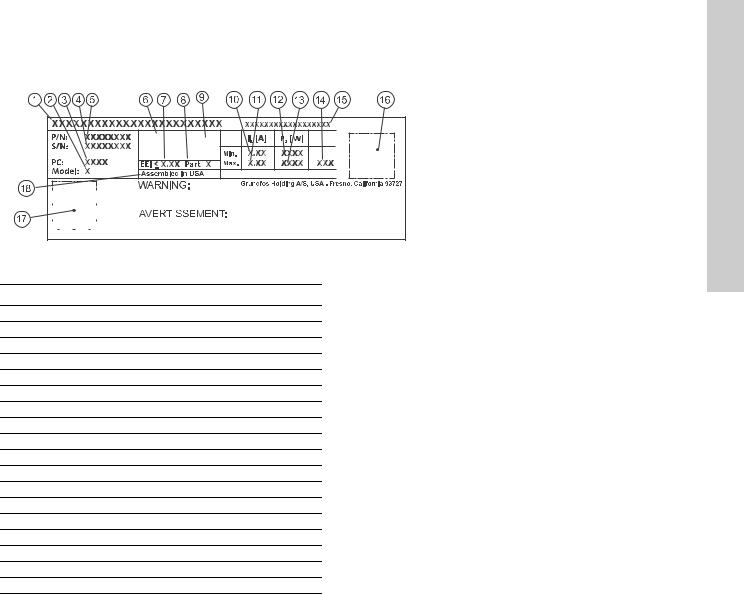
3.7 Nameplate
The pump nameplate provides the following information:
TYPE 2 |
PSI |
BOITIER DE TYPE 2 |
|
THERMALLY PROTECTED |
|
Nonsubmersible Pump |
|
|
For use with maximum 230° F water |
|
|
|
|
|
|
|
|
RISK OF ELECTRIC SHOCK. DE-ENERGIZE EQUIPMENT BEFORE REMOVAL OF COVER & SERVICING. FOR SUPPLY |
4612 |
|
|
|
|
|
|
|
|
|
CONNECTION USE COPPER WIRE SUITABLE FOR 90 °C OR EQUIVALENT. THIS PUMP HAS NOT BEEN INVESTIGATED FOR USE |
||
|
|
|
|
|
|
|
|
IN SWIMMING POOL OR MARINE AREAS. TO REDUCE THE RISK OF ELECTRIC SHOCK, SEE INSTRUCTION MANUAL FOR |
6381 |
|
|
|
|
|
|
|
|
|
PROPER INSTALLATION; ACCEPTABLE FOR INDOOR USE ONLY. |
||
|
|
|
|
|
|
|
|
|
|
|
|
|
|
|
|
|
|
|
RISQUE DE CHOC ELECTRIQUE. HORS DES EQUIPEMENT AVANT ENLEVEMENT DE LA COUVERTURE ET D’ENTRENTIEN. POUR |
TM05 |
|
|
|
|
|
|
|
|
|
LE RECCORDEMENT D’ALIMENTATION, EMPLOYEZ DES FILS QUI RESISTENT AU MOINS A 90 °C UTILISEZ UNIQUEMENT DES |
||
|
|
|
|
|
|
|
|
CONDUCTEURS DE CUIVRE. POUR RE’DUIRE LES RISQUES DE CHOC E’LECTRIQUE, CONSULTES LE MANUEL D’INSTRUCTIONS |
|
|
Contains FCC ID: OG3-RADIOM01-2G4 |
|
|||||||||
POUR UNE INSTALLATION CORRECTE. EMPLOYER UNIQUEMENT A L’INTERIEUR. |
|
|||||||||
Fig. 5 Example of nameplate
Pos. Description
1Product name
2Model
3Production code (year and week)
4Serial number
5Product number
6Enclosure type
7Energy Efficiency Index (EEI)
8Part (according to EEI)
9TF-class
10Minimum current [A]
11Maximum current [A]
12Minimum power [W]
13Maximum power [W]
14Maximum pressure
15Voltage [V] and frequency [Hz]
16QR (Quick Response) code
17Approvals (nameplate)
18Assembled in USA
English (US)
5
(US) English
3.8 Radio communication
The wireless radio in this product is class B.
Intended use
This product incorporates a radio for remote control.
The product can communicate with the Grundfos Go Remote and with other MAGNA3 pumps of the same type via the built-in radio.
Only Grundfos-approved external antennae may be connected to this product, and only by a Grundfos-approved installer.
3.9 Tools
1.2 x 8.0 |
0.6 x 3.5 |
TX20 |
5.0 |
1 |
2 |
3 |
4 |
|
5 |
6 |
7 |
TM05 6472 4712 |
Fig. 6 |
Recommended tools |
|
|
|
Pos. |
Tool |
|
Size |
|
1 |
Screwdriver, straight slot |
1.2 x 8.0 mm |
|
|
2 |
Screwdriver, straight slot |
0.6 x 3.5 mm |
|
|
3 |
Screwdriver, torx bit |
TX20 |
|
|
4 |
Hexagon key |
|
5.0 mm |
|
5 |
Open end wrench |
|
Depending on PN size |
|
6 |
Wire cutter |
|
|
|
7 |
Pipe wrench |
|
|
|
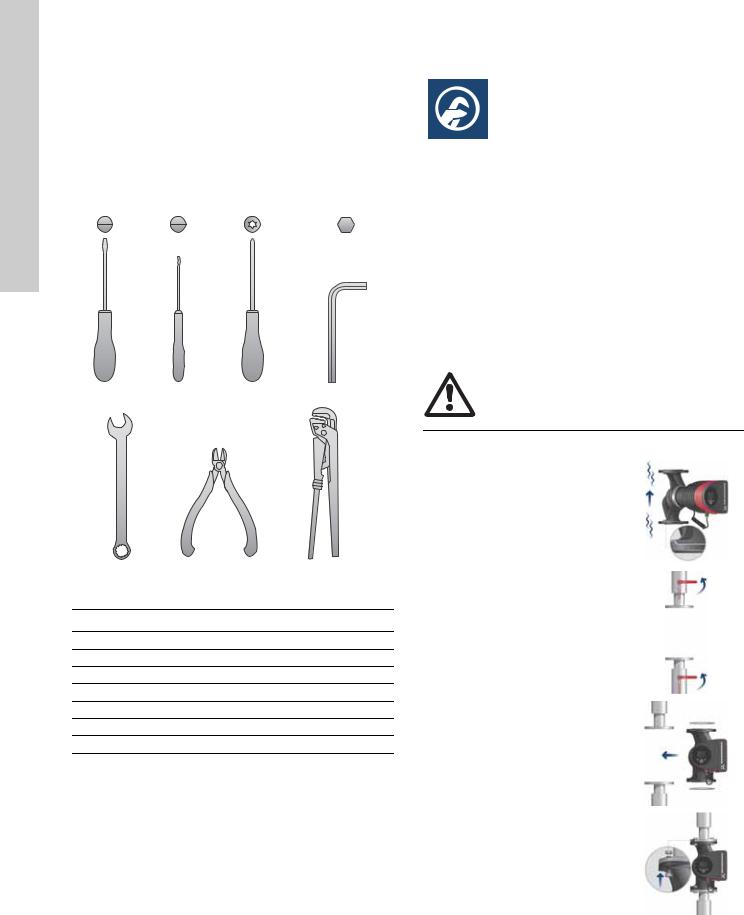
4. Mechanical installation
4.1 Installing the pump
The MAGNA3 is designed for indoor installation.
The pump must be installed in such a way that it is not stressed by the pipework.
The pump may be suspended direct in the pipes, provided that the pipework can support the pump.
Twin-head pumps are prepared for installation on a mounting bracket or base plate.
To ensure adequate cooling of motor and electronics, the following must be observed:
•Position the pump in such a way that sufficient cooling is ensured.
•The temperature of the ambient air must not exceed +104 °F (+40 °C).
Warning
Observe local regulations setting limits for manual lifting or handling.
Step |
Action |
Illustration |
|
|
|
|
|
|
Arrows on the pump housing |
|
|
|
indicate the liquid flow direction |
|
|
1 |
through the pump. The liquid |
0612 |
|
flow direction can be horizontal |
|||
|
2862 |
||
|
or vertical, depending on the |
||
|
|
||
|
control box position. |
TM05 |
|
|
|
||
|
|
|
|
|
Close the isolating valves and |
|
|
2 |
make sure that the system is not |
0612 |
|
pressurized during the |
|||
|
|||
|
|
||
|
installation of the pump. |
TM05 2863 |
|
|
|
||
|
|
|
|
3 |
Mount the pump with gaskets in |
0612 |
|
the pipework. |
|||
|
TM05 2864 |
||
|
|
||
|
|
|
|
|
Fit bolts and nuts. Use the right |
0612 |
|
4 |
size of bolts according to system |
||
|
pressure. |
TM05 2865 |
|
|
|
||
|
|
|
6
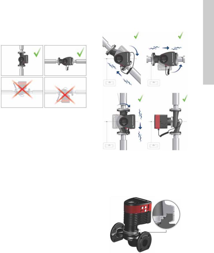
4.2 Positioning
Always install the pump with horizontal motor shaft.
•Pump installed correctly in a vertical pipe. See fig. 7, pos. A.
•Pump installed correctly in a horizontal pipe. See fig. 7, pos. B.
•Do not install the pump with vertical motor shaft. See fig. 7, pos. C and D.
A B
C D
TM05 2866 0712
Fig. 7 Pump installed with horizontal motor shaft
4.3 Control box positions
To ensure adequate cooling, the control box must be in horizontal position with the Grundfos logo in vertical position. See fig. 8.
TM05 2915 0612
Fig. 8 Pump with control box in horizontal position
If the pump head is removed before the pump is installed in the pipework, pay special attention when fitting the pump head to the pump housing:
1.Gently lower the pump head with rotor shaft and impeller into the pump housing.
2.Make sure that the contact face of the pump housing and that of the pump head are in contact before the clamp is tightened. See fig. 9.
TM05 5837 4112
Fig. 9 Fitting the pump head to the pump housing
English (US)
7
(US) English
4.4 Changing the control box position
Warning
The warning symbol on the clamp holding the pump head and pump housing together indicates that there is a risk of personal injury. See specific warnings below.
Warning
When loosening the clamp, do not drop the pump head.
Warning
Risk of escaping vapor.
Step |
Action |
Illustration |
||||||
|
|
|
|
|
|
|
|
|
|
Loosen the screw in the clamp |
|
|
|
|
|
|
|
|
holding the pump head and |
|
|
|
|
|
|
|
|
pump housing together. |
0612 |
||||||
1 |
Warning: If the screw is |
|||||||
|
loosened too much, the pump |
2867 |
||||||
|
head will be completely |
|||||||
|
disconnected from the pump |
|
|
|
|
|
TM05 |
|
|
housing. |
|
|
|
|
|
||
|
Carefully rotate the pump head |
0612 |
||||||
|
to the desired position. |
|||||||
|
2868 |
|||||||
2 |
If the pump head is stuck, |
|||||||
|
|
|
|
|
|
|||
|
loosen it with a light blow of a |
|
|
|
|
|
TM05 |
|
|
rubber mallet. |
|
|
|
|
|
||
|
|
|
|
|
|
|
|
|
|
Position the control box in |
0612 |
||||||
|
horizontal position so that the |
|||||||
3 |
Grundfos logo is in vertical |
|||||||
2869 |
||||||||
|
position. The motor shaft must |
|||||||
|
be horizontal. |
|
|
|
|
|
TM05 |
|
|
|
|
|
|
|
|
||
|
|
|
|
|
|
|
|
|
|
Due to the drain hole in the |
|
|
|
|
|
|
|
4 |
stator housing, position the gap |
|
|
|
|
|
|
|
of the clamp as shown in step |
|
|
|
|
|
|
||
|
|
|
|
|
|
TM05 2870 0612 |
||
|
4a, 4b, 4c or 4d. |
|
|
|
|
|
||
|
|
|
|
|
|
|
||
|
|
|
|
|
|
|
|
|
|
Single-head pump. |
|
|
|
|
2871 0612 |
||
|
|
|
|
|
||||
|
|
|
|
|
||||
4a |
|
|
|
|
|
TM05- |
||
gap points towards the arrow. |
|
|
|
|
|
|||
|
Position the clamp so that the |
0612 |
||||||
|
It can be in position 3 or |
|||||||
|
|
|
|
|
|
|
||
|
9 o’clock. |
|
|
|
|
|
TM05 2918 |
|
|
|
|
|
|
|
|
||
|
|
|
|
|
|
|
|
|
|
Single-head pump. |
|
|||||||
|
Note: The gap of the clamp can |
|
|
|
|
|
|||
|
|
|
|
|
|
||||
|
also be in position 6 o’clock for |
|
|
|
|
|
|||
4b |
the following pump sizes: |
1912 |
|||||||
|
• |
MAGNA3 65-XX |
|||||||
|
• |
MAGNA3 80-XX |
2899 |
||||||
|
• |
MAGNA3 100-XX. |
|||||||
|
TM05 |
||||||||
|
|
|
|
|
|
|
|
||
|
|
|
|
|
|
|
|
|
|
|
Twin-head pump. |
2873 0612 |
|||||||
|
- TM05 |
||||||||
|
Position the clamps so that the |
||||||||
4c |
gaps point towards the arrows. |
||||||||
|
They can be in position |
0612 |
|||||||
|
3 or 9 o’clock. |
||||||||
|
TM05 2917 |
||||||||
|
|
|
|
|
|
|
|
||
|
|
|
|
|
|
|
|||
|
Twin-head pump. |
|
|||||||
|
Note: The gap of the clamp can |
|
|||||||
|
also be in position 6 o’clock for |
|
|||||||
4d |
the following pump sizes: |
1912 |
|||||||
|
• |
MAGNA3 65-XX |
|||||||
|
• |
MAGNA3 80-XX |
2897 |
||||||
|
|
||||||||
|
• |
MAGNA3 100-XX. |
TM05 |
||||||
|
|
|
|
|
|
|
|
||
|
|
|
|
|
|
|
|||
|
Fit and tighten the screw |
|
|||||||
6 |
holding the clamp to minimum |
0612 |
|||||||
6 ± 0.7 ft-lbs |
|||||||||
|
2872TM05 |
||||||||
|
(8 ± 1 Nm). |
||||||||
|
|
||||||||
|
|
|
|
|
|
|
|||
|
Fit the insulating shells. |
|
|||||||
|
Note: For air conditioning and |
|
|||||||
|
cooling systems a silicone |
|
|||||||
|
sealant must be applied inside |
|
|||||||
|
the insulation shell to eliminate |
|
|||||||
|
all air gaps and prevent |
|
|||||||
7 |
condensation between the |
|
|||||||
|
pump housing and insulation |
0412 |
|||||||
|
shell. Alternatively, the pump |
||||||||
|
|
||||||||
|
may be insulated manually in |
2874 |
|||||||
|
accordance with standard |
||||||||
|
insulation practices for cooling |
TM05 |
|||||||
|
applications. |
||||||||
|
|
||||||||
|
|
|
If insulating the pump manually, do not insulate |
|
|||||
Caution |
|
|
|||||||
|
|
|
the control box or cover the control panel. |
|
|||||
|
|
|
|
||||||
8
5. Electrical installation
Carry out the electrical connection and protection according to local regulations.
Check that the supply voltage and frequency correspond to the values stated on the nameplate.
Warning
Never make any connections in the pump control box unless the electricity supply has been switched off for at least 5 minutes.
Warning
The pump must be connected to an external mains switch with a contact separation of at least 1/8 inch (3 mm) in each pole.
The ground terminal of the pump must be earth ground. Grounding or neutralization can be used for protection against indirect contact.
If the pump is connected to an electric installation where a Ground Fault Circuit Interrupt (GFCI) is used as additional protection, this circuit breaker must trip out when ground fault currents with DC content (pulsating DC) occur.
•If rigid conduit is to be used, the hub must be connected to the conduit system before it is connected to the terminal box of the pump.
•The pump must be connected to an external mains switch.
•The pump requires no external motor protection.
•The motor incorporates thermal protection against slow overloading and blocking.
•When switched on via the power supply, the pump will start pumping after approx. 5 seconds.
Note |
The number of starts and stops via the power |
|
supply must not exceed four times per hour. |
||
|
5.1 Supply voltage
1 x 115 V ± 10 %, 50/60 Hz, PE.
1 x 208-230 V ± 10 %, 50/60 Hz, PE.
See Pump Nameplate for rated supply voltage
The voltage tolerances are intended for mains voltage variations. They should not be used for running pumps at other voltages than those stated on the nameplate.
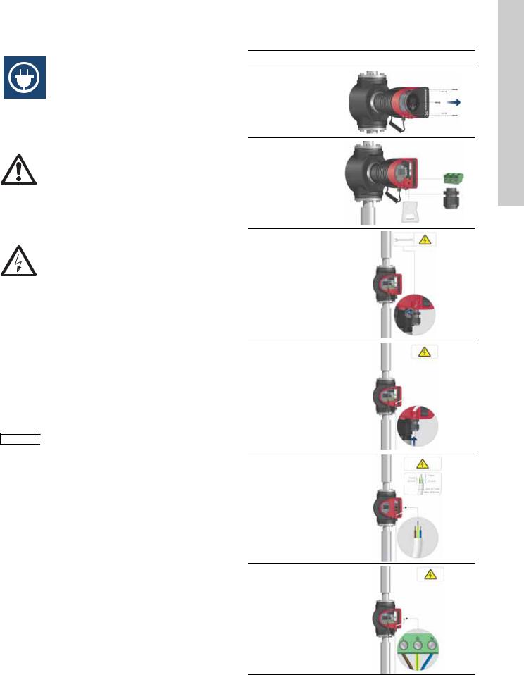
5.2 Connection to the power supply
Step Action |
Illustration |
Remove the front
1cover from the control box.
Locate the power supply plug and
2conduit adapter in the box supplied with the pump.
Connect the
3conduit adapter to the control box.
Pull the power supply cable
4through the conduit adapter and thread on conduit.
Strip the cable
5conductors as illustrated.
Connect the cable conductors to the
6power supply plug. L - L or L1 Ground - Ground N - N or L2
TM05 2875 0612
TM05 2876 0612
TM05 2877 0612
TM05 2878 0612
TM05 5534 3812
TM05 2880 0612
English (US)
9
English |
|
Insert the power |
(US) |
|
|
|
supply plug into |
|
|
|
|
|
7 |
the male plug in |
|
|
the pump control |
|
|
box. |
|
Tighten the |
|
8 |
conduit adapter. |
|
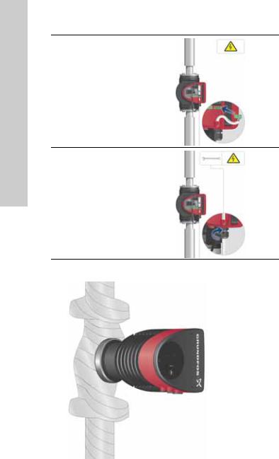
Refit the front |
||
|
||
|
cover. |
TM05 5549 3812
Fig. 10 Insulation of pump housing and pipework
TM05 2881 0612
TM05 2882 0612
10
5.3 Connection diagram
|
|
|
|
|
|
|
|
|
|
|
|
|
|
|
|
|
|
|
|
|
|
|
|
|
|
|
|
|
|
|
|
External switch |
|||||||||||
|
|
|
|
|
|
|
|
|
|
|
|
|
|
|
|
|
|
|
|
|
|
|
|
|
|
|
|
|
|
|
|
|
|
|
|
|
|
|
|
|
|
|
|
|
|
|
|
|
|
|
|
|
|
|
|
|
|
|
|
|
|
|
|
|
|
|
|
|
|
|
|
|
|
|
|
|
|
|
|
|
|
|
|
|
|
|
|
|
|
|
|
|
|
|
|
|
|
|
|
|
|
ELCB |
|
|
|
|
|
|
|
|
|
|
|
|
|
|
|
|
|
|
|
||||||||||
|
|
|
|
|
|
|
|
|
|
|
|
|
|
|
|
|
|
Fuse |
|
|
|
|
|
|
|
|
|
|
|
||||||||||||||
|
|
|
|
|
|
|
|
|
|
|
|
|
|
|
|
|
|
|
|
|
|
||||||||||||||||||||||
|
|
|
|
|
|
|
|
|
|
|
|
|
|
|
|
|
|
|
|
|
|
|
|
|
|
|
|
|
|
|
|
|
|
|
|
|
|
|
|
||||
|
|
|
|
|
|
|
|
|
|
|
|
|
|
|
|
|
|
|
|
|
|
|
|
|
|
|
|
|
|
|
|
|
|
|
|
|
|
|
|
||||
|
|
|
|
|
|
|
|
|
|
|
|
|
|
|
|
|
|
|
|
|
|
||||||||||||||||||||||
|
|
|
|
|
|
|
|
|
|
|
|
|
|
|
|
|
|
|
|
|
|
|
|
|
|
|
(min. 10 A, time lag) |
|
|
|
|
|
|
|
|
|
|
TM03 2397 0312 |
|||||
|
|
|
|
|
|
|
|
|
|
|
|
|
|
|
|
|
|
|
|
|
|
|
|
|
|
|
|
|
|
|
|
|
|
|
|
|
|||||||
|
|
|
|
|
|
|
|
|
|
|
|
|
|
|
|
|
|
|
|
|
|||||||||||||||||||||||
|
|
|
|
|
|
|
|
|
|
|
|
|
|
|
|
|
|
|
|
|
|
|
|
|
|
|
|
|
|
|
|
|
|
|
|
|
|
|
|
|
|
|
|
|
|
|
|
|
|
|
|
|
|
|
|
|
|
|
|
|
|
|
|
|
|
|
|
|
|
|
|
|
|
|
|
|
|
|
|
|
|
|
|
|
|
|
|
|
|
|
|
|
|
|
|
|
|
|
|
|
|
|
|
|
|
|
|
|
|
|
|
|
|
|
|
|
|
|
|
|
|
|
|
|
|
|
|
|
|
|
|
|
|
|
|
|
|
|
|
|
|
|
|
|
|
|
|
|
|
|
|
|
|
|
|
|
|
|
|
|
|
|
|
|
|
|
|
|
|
|
|
|
|
|
|
|
|
|
|
|
|
|
|
|
|
|
|
|
|
|
|
|
|
|
|
|
|
|
|
|
|
|
|
|
|
|
|
|
|
|
|
|
|
|
|
|
|
|
|
|
|
|
|
|
|
|
|
|
|
|
|
|
|
|
|
|
|
|
|
|
|
|
|
|
|
|
|
|
|
|
|
|
|
|
|
|
|
|
|
|
|
|
|
|
|
|
|
|
|
|
|
|
|
|
|
|
|
|
|
|
|
|
|
|
|
|
|
|
|
|
|
|
|
|
|
|
|
|
|
|
|
|
|
|
|
|
|
|
|
|
|
|
|
|
|
|
|
|
|
|
|
|
|
|
|
|
|
|
|
|
|
|
|
|
|
|
|
|
|
|
|
|
|
|
|
|
|
|
|
|
|
|
|
|
|
|
|
|
|
|
|
|
|
|
|
|
|
|
|
|
|
|
|
|
|
|
|
|
|
|
|
|
|
|
|
|
|
|
|
|
|
|
|
|
|
Fig. 11 Example of typical connection, 1 x 230 |
|
|
|
|
|
|
|
|
|
|
|
|
|
||||||||||||||||||||||||||||||
V ± 10 %, 50/60 Hz |
|||||||||||||||||||||||||||||||||||||||||||
|
|
|
|
|
|
|
|
|
All cables used must be connected in |
||||||||||||||||||||||||||||||||||
Note |
|
||||||||||||||||||||||||||||||||||||||||||
|
accordance with local regulations. |
|
|
|
|
|
|
|
|
|
|
|
|
|
|
||||||||||||||||||||||||||||
|
|
|
|
|
|
|
|
|
|
|
|
|
|
|
|
|
|
|
|
|
|
|
|||||||||||||||||||||
5.4 Connection to external controllers
Fig. 12 Connection diagram
Max. |
|
|
|
3 |
|
|
|
|
|
|
|
Max. |
|
|
|
|
|
|
|
|
|
|
|
|
|||
24 V DC |
|
24V |
|
IN |
|
|
|
250 V AC |
|||||
22 mA |
|
|
|
|
|
2 A AC1 |
|||||||
|
Vcc |
|
Signal |
|
|||||||||
|
|
|
|
|
|
||||||||
|
|
|
|
|
|
||||||||
0-10 V DC |
|
|
|
|
|
|
|
|
|
|
|
Min. |
|
|
|
|
|
|
|
|
|
|
|
|
|||
|
|
|
|
|
|
|
|
|
|
|
5 V DC |
||
|
|
|
|
|
|
|
|
|
|
|
|
||
|
|
|
|
|
|
|
|
|
|
|
|
||
|
|
Vcc |
|
Signal |
20 mA |
||||||||
|
|
|
|
|
|
||||||||
4-20 mA |
|
|
|
|
|
|
I |
|
|
|
|||
|
|
|
|
|
|
|
|
|
|||||
|
|
|
|
|
|
|
|
|
|||||
|
|
|
|
|
|
|
|
|
|
||||
|
|
|
|
2 |
|
|
|
|
|
|
|
|
|
|
|
|
|
|
|
|
|
|
|
|
|
|
|
|
|
|
|
|
|
|
|
|
|
|
|
|
|
|
|
|
|
|
|
|
|
|
|
|
|
|
|
|
|
M |
M |
S/S |
|
|
|
|
NC NO C |
||||
|
|
A |
I |
|
|
|
|
||||||
|
|
|
|
||||||||||
|
|
|
|
|
|
|
|
|
|
|
|
|
|
1 |
TM05 2901 1912 - TM05 3343 1212
Warning
Wires connected to supply terminals, outputs NC, NO, C and start/stop input must be separated
from each other and from the supply by reinforced insulation.
Concerning demands on signal wires and signal transmitters, see section 19. Technical data.
Use screened cables for external on/off switch, digital input, sensor and setpoint signals.
Note |
All cables used must be heat-resistant up to |
|
+185 °F (+85 °C). |
||
|
5.5 Input/output communication
•Relay outputs
Alarm, ready and operating indication via signal relay.
•Digital input
–Start/Stop (S/S)
–Min. curve (MI)
–Max. curve (MA).
•Analog input
0-10 V or 4-20 mA control signal.
To be used for external control of the pump or as sensor input for the control of the external setpoint.
The 24 V supply from pump to sensor is optional and is normally used when an external supply is not available.
English (US)
11
(US) English
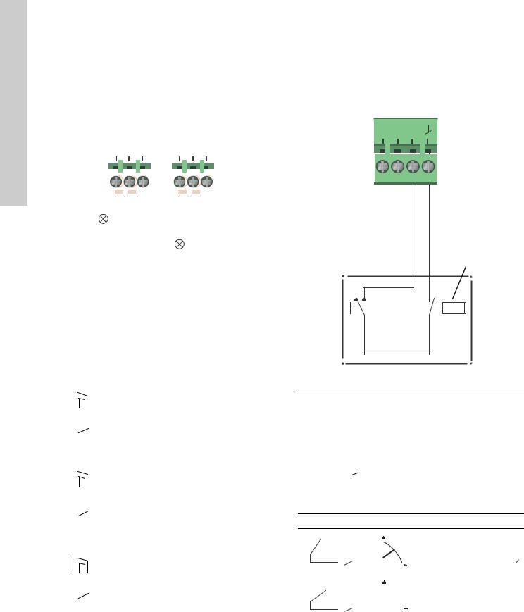
5.5.1 Relay outputs
See fig. 12, pos. 1.
The pump incorporates two signal relays with a potential-free changeover contact for external fault indication.
The function of the signal relay can be set to "Alarm", "Ready" or "Operation" on the pump control panel or with the Grundfos GO Remote.
The relays can be used for outputs up to 250 V and 2 A.
Relay 1 |
|
Relay 2 |
|||||||||
|
|
|
|
|
|
|
|
|
|
|
|
NC NO C |
|
NC NO C |
|||||||||
|
|
|
|
|
|
|
|
|
|
|
|
|
|
|
|
|
|
|
|
|
|
|
|
|
|
|
|
|
|
|
|
|
|
|
|
|
|
|
|
|
|
|
|
|
|
|
|
5.5.2 Digital inputs
See fig. 12, pos. 2.
The digital input can be used for external control of start/stop or forced max. or min. curve.
If no external on/off switch is connected, the jumper between terminals Start/Stop (S/S) and frame ( ) should be maintain ed. This connection is the factory setting.
M M
A I S/S
|
|
|
|
|
|
|
|
|
|
Alarm |
|
|
|
|
|
|
3338 1212 |
||
|
|
|
|
|
|
|
|
|
|
|
|
|
|
|
|
|
|
|
|
|
|
|
Operation |
|
|||||
|
|
|
|
TM05 |
|||||
Fig. 13 Relay output |
|
|
|
|
|
|
|||
|
|
|
|
|
|
||||
|
|
|
|
|
|
|
|||
|
|
|
|
|
|
|
|
|
|
Contact symbol |
|
|
|
|
Function |
|
|||
|
|
|
|
|
|
|
|
|
|
|
|
NC |
|
|
|
Normally closed |
|
||
|
|
NO |
|
|
|
|
Normally open |
|
|
|
|
C |
|
|
|
|
Common |
|
|
The functions of the signal relays appear from the table below:
Signal relay |
Alarm signal |
|||||||||
|
|
|
|
|
|
|
|
|
|
|
|
|
|
|
|
|
|
|
|
Not activated: |
|
|
|
|
|
|
|
|
|
|
||
|
|
|
|
|
|
|
|
|
||
|
|
1 |
2 |
3 |
|
|
|
• |
The power supply has been switched off. |
|
|
|
NC NO |
C |
C |
|
• The pump has not registered a fault. |
||||
|
NC NO |
|
|
|||||||
|
1 |
2 |
|
3 |
|
|
|
|||
|
|
|
|
|
|
|
|
|
|
|
|
|
|
|
|
|
|
|
|
Activated: |
|
|
|
|
|
|
|
|
|
|
||
|
|
|
|
|
|
|
|
|
||
|
|
|
|
|
|
|
|
• |
The pump has registered a fault. |
|
1 |
2 |
|
3 |
|
||||||
|
NC NO |
|
C |
|
|
|||||
Signal relay |
Ready signal |
|||||||||
|
|
|
|
|
|
|
|
|
|
|
|
|
|
|
|
|
|
|
|
Not activated: |
|
|
|
|
|
|
|
|
|
|
||
|
|
|
|
|
|
|
|
|
||
|
|
1 |
2 |
3 |
|
|
|
• The pump has registered a fault and is |
||
|
NC NO |
C |
C |
|
|
unable to run. |
||||
|
|
NC NO |
3 |
|
|
|
||||
|
1 |
2 |
|
|
|
|
||||
|
|
|
|
|
|
|
|
|
|
|
|
|
|
|
|
|
|
|
|
Activated: |
|
|
|
|
|
|
|
|
|
|
• |
The pump has been set to stop, but is ready |
|
|
|
|
|
|
|
|
|
||
|
|
|
|
|
|
|
|
|
to run. |
|
1 |
2 |
|
3 |
|
• |
|||||
|
NC NO |
|
C |
The pump is running. |
||||||
|
|
|
|
|||||||
|
|
|
|
|
|
|
||||
Signal relay |
Operating signal |
|||||||||
|
|
|
|
|
|
|
|
|
|
|
|
|
|
|
|
|
|
|
|
Not activated: |
|
|
|
|
|
|
|
|
|
|
||
|
|
|
|
|
|
|
|
|
||
|
1 |
2 |
|
3 |
|
• |
The pump is not running. |
|||
|
1 |
2 |
3 |
|
|
|
|
|
||
|
|
NC NO |
C |
|
|
|
|
|
||
|
NC NO |
|
C |
|
|
|
||||
|
|
|
|
|
|
|
|
|
|
|
|
|
|
|
|
|
|
|
|
Activated: |
|
|
|
|
|
|
|
|
|
|
||
|
|
|
|
|
|
|
|
|
||
|
|
|
|
|
|
|
|
• |
The pump is running. |
|
1 |
2 |
|
3 |
|
||||||
|
NC NO |
|
C |
|
|
|||||
On/off timer
Start/stop
TM05 3339 1212
Fig. 14 Digital input
Contact symbol |
Function |
|
|
|
|
M |
Max. curve |
|
A |
100 % speed |
|
M |
Min. curve |
|
I |
25 % speed |
|
S/S |
Start/Stop |
|
|
|
Frame connection |
|
|
|
|
|
|
External start/stop
The pump can be started or stopped via the digital input.
Start/stop
|
|
|
S/S |
H |
|
|
Normal duty |
|||
|
|
|
|
|
||||||
|
|
|
|
|
|
|
||||
|
|
|
|
|
|
|
|
|||
|
|
|
|
|
|
|
|
Note: Factory setting with |
||
|
|
|
|
|
|
|
|
Q jumper between S/S and |
|
. |
|
|
|
|
|
|
|
|
|||
|
|
|
|
|
|
|
||||
|
|
|
S/S |
H |
|
|
Stop |
|||
|
|
|
|
|
||||||
|
|
|
|
|
|
|
|
|||
|
|
|
|
|
|
|
||||
|
|
|
|
|
|
|
|
Q |
||
|
|
|
|
|
|
|
|
|||
|
|
|
|
|
|
|
|
|
|
|
12
Loading...