


 Loading...
GRUNDFOS INSTRUCTIONS
SCALA2
Installation and operating instructions
Other languages
http://net.grundfos.com/qr/i/98880508
2

SCALA2
English (GB)
Installation and operating instructions. . . . . . . . . . . . . . . . . . . . . . . . . . . . . . . . . 4
(AR) ة يبرعلا |
|
ليغ شتلا و ب يكرتلا تا ميلعت . . . . . . . . . . . . . . . . . . . . . . . . . . . . . . . . . . . . . . |
45 |
Declaration of conformity . . . . . . . . . . . . . . . . . . . . . . . . . . . . . . . . . . . . . . . . . |
46 |
Table of contents
3
(GB) English
English (GB) Installation and operating instructions
Original installation and operating instructions
These installation and operating instructions describe Grundfos SCALA2 domestic water supply pumps.
Sections 1-5 give the information necessary to be able to unpack, install and start up the product in a safe way.
Sections 6-14 give important information about the product, as well as information on service, fault finding and disposal of the product.
CONTENTS
Page
11. |
|
Taking the product out of operation |
19 |
12. |
|
Fault finding the product |
20 |
12.1 |
Grundfos Eye operating indications |
20 |
|
12.2 |
Fault resetting |
20 |
|
12.3 |
Fault finding chart |
21 |
|
13. |
|
Technical data |
24 |
13.1 |
Operating conditions |
24 |
|
13.2 |
Mechanical data |
24 |
|
13.3 |
Electrical data |
24 |
|
13.4 |
Dimensions and weights |
24 |
|
14. |
Disposing of the product |
24 |
|
1. |
General information |
5 |
1.1 |
Target group |
5 |
1.2 |
Hazard statements |
5 |
1.3 |
Notes |
5 |
2. |
Receiving the product |
5 |
2.1 |
Inspecting the product |
5 |
2.2 |
Scope of delivery |
5 |
3. |
Installing the product |
5 |
3.1 |
Location |
5 |
3.2 |
System sizing |
6 |
3.3 |
Mechanical installation |
6 |
3.4 |
Electrical connection |
9 |
4. |
Starting up the product |
10 |
4.1 |
Priming the pump |
10 |
4.2 |
Starting the pump |
10 |
4.3 |
How to set the correct pressure |
11 |
4.4 |
Shaft seal run-in |
11 |
5. |
Handling and storing the product |
12 |
5.1 |
Handling the product |
12 |
5.2 |
Storing the product |
12 |
6. |
Product introduction |
12 |
6.1 |
Product description |
12 |
6.2 |
Intended use |
12 |
6.3 |
Pumped liquids |
12 |
6.4 |
Identification |
13 |
7. |
Control functions |
14 |
7.1 |
Menu overview, SCALA2 |
14 |
8. |
Setting the product |
15 |
8.1 |
Setting the outlet pressure |
15 |
8.2Locking and unlocking the operating
|
panel |
15 |
8.3 |
Expert settings, SCALA2 |
15 |
8.4 |
Resetting to factory settings |
17 |
9. |
Servicing the product |
17 |
9.1 |
Maintaining the product |
17 |
9.2 |
Customer service information |
18 |
9.3 |
Service kits |
18 |
10. |
Starting up the product after standstill |
19 |
10.1 |
Deblocking the pump |
19 |
Read this document and the quick guide before installing the product. Installation and operation must comply with local regulations and accepted codes of good practice.
This appliance can be used by children aged from 8 years and above and persons with reduced physical, sensory or mental capabilities or lack of experience and knowledge if they have been given supervision or instruction concerning use of the appliance in a safe way and understand the hazards involved.
Children shall not play with the appliance. Cleaning and user maintenance shall not be made by children without supervision.
4
1. General information
1.1 Target group
These installation and operating instructions are intended for professional as well as non-professional users.
1.2 Hazard statements
The symbols and hazard statements below may appear in Grundfos installation and operating instructions, safety instructions and service instructions.
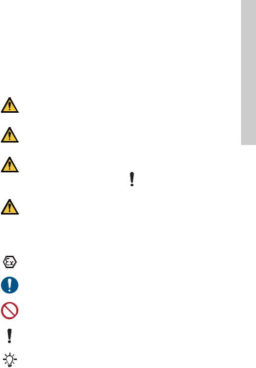
DANGER
Indicates a hazardous situation which, if not avoided, will result in death or serious personal injury.
WARNING
Indicates a hazardous situation which, if not avoided, could result in death or serious personal injury.
CAUTION
Indicates a hazardous situation which, if not avoided, could result in minor or moderate personal injury.
The hazard statements are structured in the following way:
SIGNAL WORD
Description of hazard
Consequence of ignoring the warning.
-Action to avoid the hazard.
1.3Notes
The symbols and notes below may appear in Grundfos installation and operating instructions, safety instructions and service instructions.
Observe these instructions for explosion-proof products.
A blue or grey circle with a white graphical symbol indicates that an action must be taken.
A red or grey circle with a diagonal bar, possibly with a black graphical symbol, indicates that an action must not be taken or must be stopped.
If these instructions are not observed, it may result in malfunction or damage to the equipment.
Tips and advice that make the work easier.
2. Receiving the product
2.1 Inspecting the product
Check that the product received is in accordance with the order.
Check that the voltage and frequency of the product match the voltage and frequency of the installation site. See section 6.4.1 Nameplate.
2.2 Scope of delivery
The box contains the following items:
•1 Grundfos SCALA2 pump
•1 quick guide
•1 safety instructions booklet.
3. Installing the product
3.1 Location
The pump can be installed indoors or outdoors, but it must not be exposed to frost.
We recommend that you install the pump near a drain or in a drip tray connected to a drain in order to lead away possible condensation from cold surfaces.
Install the pump in such a way that no undesirable collateral damage can arise due to leakage.
If the unlikely event of an internal leakage occurs, the liquid will be drained through the bottom of the pump.
3.1.1 Minimum space
The pump requires a minimum space of 430 x 215 x 325 mm (17 x 8.5 x 12.8 inches).
Even though the pump does not require much space, we recommend that you leave enough space for service and maintenance access.
3.1.2 Installing the product in frosty environment
Protect the pump from freezing if it is to be installed outdoors where frost may occur.
English (GB)
5
English |
3.2 System sizing |
maximum pump pressure. |
|
|
Make sure that the system in which the |
|
pump is incorporated is designed for the |
(GB) |
The pump is factory-set to 3 bar (44 psi) outlet |
pressure which can be adjusted according to the |
|
|
system in which it is incorporated. |
The tank precharge pressure is 1.25 bar (18 psi).
In case of suction lift of more than six metres, the pipe resistance on the outlet side must be at least two metres water column or 3 psi at any given flow in order to obtain optimum operation.
3.3 Mechanical installation
DANGER
Electric shock
Death or serious personal injury
-Switch off the power supply before starting any work on the product. Make sure that the power supply cannot be accidentally switched on.
3.3.1Positioning the product
Always mount the pump on the base plate in a horizontal position with a maximum inclination angle of ± 5 °.
3.3.2 Foundation
Fasten the pump to a solid horizontal foundation by means of screws through the holes in the base plate. See figs 1 and 2.
TM06 5729 5315
Fig. 1 |
Horizontal foundation |
|
C |
B |
1015 |
|
A |
TM06 3809 |
Fig. 2 |
Base plate |
|
|
[mm (inches)] |
|
A |
181 (7.13) |
|
B |
130 (5.12) |
|
C |
144 (5.67) |
|
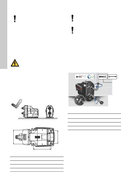
3.3.3 Connecting the piping system
Make sure that the pump is not stressed by the piping system.
Always loosen and tighten the union nuts on the inlet and outlet ports by hand. Damage to the inlet and outlet parts increases the risk of leakage.
1.Turn the union nuts by hand to loosen the inlet and outlet ports. See fig. 3.
2.Seal the pipe fittings with thread sealing tape.
3.Carefully screw the inlet and outlet connections to the pipe fittings using a pipe wrench or similar tool. Keep the union nut on the pipe fitting if you have removed it from the pump.
The pump is equipped with flexible connections,
± 5 °, to facilitate the connection of inlet and outlet pipes.
4.Fasten the connections to the inlet and outlet. Hold the connection with one hand and tighten the union nut with the other hand.
|
|
|
|
|
|
|
1915 |
|
|
|
|
|
|
|
|
|
|
|
|
|
|
|
|
|
|
|
|
|
|
|
|
2 |
|
|
|
|
|
|
4318 |
1 |
|
|
|
|
|
|
TM06 |
3 |
|
|
|
|
|
|
|
|
|
|
|
|
|
||
|
|
|
|
|
|
|
Fig. 3 How to fit the connections
Pos. Description
1Inlet and outlet port
2Union nut
3Pipe fitting
6
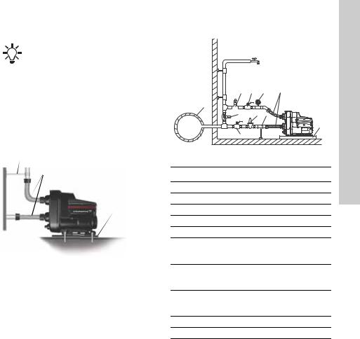
3.3.4 How to reduce noise in the installation
We recommend to use flexible hoses and mount the pump on a vibration-damping
rubber pad.
Vibrations from the pump may be transferred to the surrounding structure and create noise in the 20-1000 Hz spectrum, also called the bass spectrum.
Correct installation using a vibration-damping rubber pad, flexible hoses and correctly placed pipe hangers for rigid pipes can reduce the noise experienced by up to 50 %. See fig. 4.
Place pipe hangers for the rigid pipes close to the connection of the flexible hose.
Pipe hanger for rigid pipe
Flexible hose
Rubber pad
TM06 4321 1915
Fig. 4 How to reduce noise in the installation
3.3.5 Installation examples
Fittings, hoses and valves are not supplied with the pump.
We recommend to follow the installation examples in sections 3.3.6 to 3.3.8.
3.3.6 Mains water pressure boosting
 1
1
 2
2
7 |
3 |
9 |
4 |
10 |
|
|
2015 |
|
|
|
|
5 |
6 |
2 |
4347 |
|
|
8 |
|
3 |
|
|
TM06 |
|
|
|
Fig. 5 Mains water pressure boosting
Pos. Description
1Highest tapping point
2Pipe hangers and supports
3Isolating valves
4Flexible hoses
5Bypass valve
Optional pressure-reducing valve on the
6inlet side if the inlet pressure can exceed 10 bar (145 psi)
Optional pressure-relief valve on the outlet
7side if the installation cannot withstand a pressure of 6 bar (87 psi)
Drip tray. Install the pump on a small stand
8to prevent the ventilation holes from being flooded.
9Pressure gauge
10 Mains water pipe
English (GB)
7
(GB) English
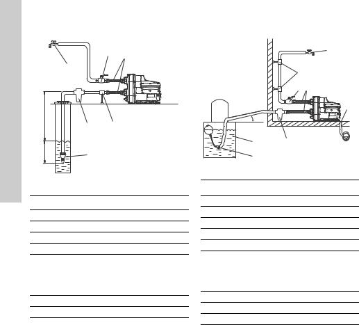
3.3.7 Suction from a well |
|
|
|
2 |
3 |
|
|
|
|
1 |
|
H1 |
|
|
|
5 |
4 |
H2 |
6 |
4349 4117 |
|
|
TM06 |
Fig. 6 |
Suction from a well |
|
Pos. Description
1Highest tapping point
2Isolating valve
3Flexible hoses
4Pipe support
Inlet filter.
If the water may contain sand, gravel or
5other debris, please install a filter on the inlet side to protect the pump and installation.
6Foot valve with strainer (recommended). H1 Maximum suction lift is 8 m (26 ft).
H2 |
Inlet pipe must be submersed at least 0.5 |
|
m (1.64 ft). |
||
|
3.3.8 Suction from freshwater tank
|
|
1 |
|
2 |
|
|
3 |
4 |
|
|
5 |
7 |
6 |
43484117 |
A |
|
|
8 |
|
TM06 |
Fig. 7 Suction from freshwater tank
Pos. Description
1Highest tapping point
2Pipe hangers
3Isolating valve
4Flexible hoses
5Drain to sewer
Inlet filter.
If the water may contain sand, gravel or
6other debris, please install a filter on the inlet side to protect the pump and installation.
7Freshwater tank
8Foot valve with strainer (recommended) A Minimum 1 ° inclination
8
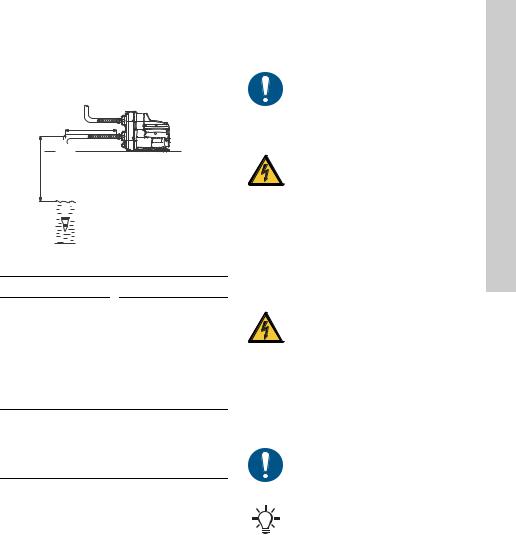
3.3.9 Inlet pipe length
The overview below shows the different possible inlet pipe lengths, depending on the vertical pipe length.
The overview is only intended as a guide.
L |
H 


 TM06 4372 4117
Fig. 8 Inlet pipe length
DN 32 |
DN 40 |
H |
|
L |
[m (ft)] |
[m (ft)] |
|
|
|
|
0 (0) |
68 |
(223) |
3 (10) |
43 |
(141) |
6 (20) |
17 (56) |
|
7 (23) |
9 |
(30) |
8 (26) |
0 (0) |
|
H |
|
L |
[m (ft)] |
[m (ft)] |
|
|
|
|
0 (0) |
207 |
(679) |
3 (10) |
129 |
(423) |
6 (20) |
52 (171) |
|
7 (23) |
26 |
(85) |
8 (26) |
0 |
(0) |
Preconditions:
Maximum flow velocity: 1 l/s (16 gpm).
Inside roughness of pipes: 0.01 mm (0.0004 inch).
Size |
Inside pipe diameter |
Pressure loss |
|
[mm (inches)] |
[m/m (psi/ft)] |
||
|
|||
|
|
|
|
DN 32 |
28 (1.1) |
0.117 (5/100) |
|
DN 40 |
35.2 (1.4) |
0.0387 (1.6/100) |
3.4 Electrical connection
Carry out the electrical connection according to local regulations.
Check that the supply voltage and frequency correspond to the values stated on the nameplate.
DANGER
Electric shock
Death or serious personal injury
-Switch off the power supply before starting any work on the product. Make sure that the power supply cannot be accidentally switched on.
DANGER
Electric shock
Death or serious personal injury
-The pump must be earthed.
-The pump is supplied with a grounding conductor and grounding-type attachment plug. To reduce the risk of electric shock, be certain that the pump is connected only to a properly grounded, grounding type receptacle (protective earthing).
-If national legislation requires a Residual Current Device (RCD), a Ground Fault Circuit Interrupter (GFCI), or equivalent in the electrical installation, this must be type B (according to UL/IEC 61800-5-1) or better, due to the nature of the constant DC leakage current.
If the power supply cable is damaged, it must be replaced by the manufacturer, his service agent or similarly qualified persons in order to avoid hazard.
We recommend that you fit the permanent installation with a residual-current circuit breaker (RCCB) with a tripping current less than 30 mA.
3.4.1 Motor protection
The pump incorporates current and temperature dependent motor protection.
English (GB)
9
(GB) English
3.4.2 Plug connection
DANGER
Electric shock
Death or serious personal injury
-Check that the power plug delivered with the product is in compliance with local regulations.
-Make sure that the pump is connected only to a properly grounded, grounding-type receptacle (protective earthing).
-The protective earth of the power outlet must be connected to the protective earth of the pump. The plug must therefore have the same PE connection system as the power outlet. If not, use a suitable adapter.
3.4.3Connection without plug
The electrical connection must be carried out by an authorised electrician in accordance with local regulations.
DANGER
Electric shock
Death or serious personal injury
-The pump must be connected to an external main switch with a minimum contact gap of 3 mm (0.12 inch) in all poles.
4. Starting up the product
Do not start the pump until it has been filled with liquid.
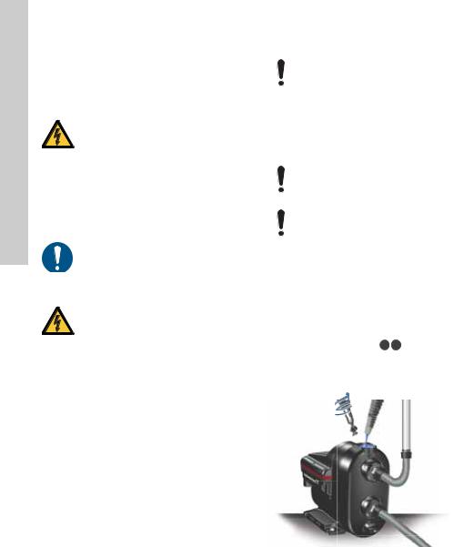
4.1 Priming the pump
1.Unscrew the priming plug and pour minimum 1.7 litres (0.45 gallons) of water into the pump housing. See fig. 9.
2.Screw the priming plug on again.
If the suction depth exceeds 6 m (20 ft), it may be necessary to prime the pump more than once.
Always tighten priming and drain plugs by hand.
4.2 Starting the pump
1.Open a tap to prepare the pump for venting.
2.Insert the power plug into the socket or turn on the power supply and the pump will start.
3.When water flows without air, close the tap.
4.Open the highest tapping point in the installation, preferably a shower.
5.Adjust the pressure setpoint to the required
pressure by means of the 
 buttons. See section 4.3 How to set the correct pressure.
6.Close the tapping point.
Startup has been completed.
TM06 4204 1615
Fig. 9 Priming the pump
10
4.3 How to set the correct pressure
The pump can be set to provide a water pressure between 1.5 to 5.5 bar (22 to 80 psi) at intervals of 0.5 bar (7 psi).
The factory setting is 3 bar (44 psi). See section
3.2 System sizing.
We recommend to use the default pressure of 3.0 bar (44 psi) which will suit most applications.
The difference between the inlet pressure and outlet pressure must not exceed 3.5 bar (51 psi).
Example: If the inlet pressure is 0.5 bar (7 psi), the maximum outlet pressure is 4 bar (58 psi).
If you set the pressure too high, this might cause the pump to operate for up to three minutes after the tap is turned off.
4.3.1 Boosting from a well or a tank
If you are boosting from a well or a tank, make sure not to set the pressure setpoint too high. The difference between the inlet pressure and outlet pressure must not exceed 3.5 bar (51 psi).
Maximum setpoint |
|
[bar (psi)] |
||||
|
|
|
|
|
|
|
Well application |
3.0 (44) |
|||||
Tank below ground level |
3.5 (51) |
|||||
Tank above ground level |
4.0 (58) |
|||||
|
|
|
|
|
|
|
|
|
|
|
|
|
|
|
|
|
|
|
|
|
TM07 0075 4117 |
TM07 0076 4117 |
Fig. 10 Boosting from a well or a tank
4.3.2 Boosting from the mains
The pressure settings 4.5, 5.0 and 5.5 bar (65, 73 and 80 psi) require a positive inlet pressure and these settings must only be used when boosting from the water mains.
TM07 0074 4117
Fig. 11 Boosting from the mains
4.3.3 Self-learning setpoint
If the pump cannot reach the user-defined pressure setpoint, the self-learning function will automatically lower the setpoint. See section 8.3.2 Self-learning function.
4.4 Shaft seal run-in
The shaft seal faces are lubricated by the pumped liquid. A slight leakage from the shaft seal of up to 10 ml per day or 8 to 10 drops per hour may occur.
When the pump is started up for the first time, or when the shaft seal has been replaced, a certain run-in period is required before the leakage is reduced to an acceptable level. The time required for this depends on the operating conditions, that is, every time the operating conditions change, a new run-in period will be started.
Under normal conditions, the leaking liquid will evaporate. As a result, no leakage will be detected.
The leakage is visible where the screws are mounted on the base plate. If the unlikely event of an internal leakage occurs, the liquid will be drained through the bottom of the pump. Install the pump in such a way that no undesirable collateral damage can arise.
English (GB)
11
(GB) English
5. Handling and storing the product
5.1 Handling the product
Take care not to drop the pump as it may break.
5.2 Storing the product
If the pump is to be stored for a period of time, for example during the winter, drain it and store it indoors in a dry location. See section 10. Starting up the product after standstill.
Temperature range during storing must be -40 to 70 °C (-40 to 158 °F).
Maximum relative humidity during storing: 95 % RH.
6. Product introduction
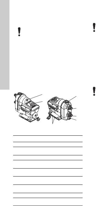
6.1 Product description
1
2


 3
3 


 4
4
9
5
6 |
1015 |
|
|
7 |
3818 |
|
|
8 |
TM06 |
|
Fig. 12 Grundfos SCALA2 pump
Pos. Description
1Air valve for built-in pressure tank
2Operating panel. See section 7. Control functions.
3Nameplate. See section 6.4.1 Nameplate.
4Plug for access to pump shaft. See section 10.1 Deblocking the pump.
5Priming plug. See section 4.1 Priming the pump.
6Outlet opening. See section
3.3.3Connecting the piping system.
7Inlet opening. See section
3.3.3Connecting the piping system.
8Drain plug. See section 6.4 Identification.
9Ventilation holes. They must not be flooded.
The inlet and outlet openings include flexible connections of ± 5 °.
6.2 Intended use
This pump has been evaluated for use with water only.
Only use SCALA2 pumps according to the specifications stated in these installation and operating instructions.
The pump is suitable for pressure boosting of fresh water in domestic water supply systems.
6.3 Pumped liquids
The pump is designed for fresh water with a maximum chloride content of 300 ppm and a free chlorine content below 1 ppm.
The pump is not suitable for these liquids:
•liquids containing long fibres
•flammable liquids (oil, petrol, etc.)
•aggressive liquids.
If the water can contain sand, gravel or other debris, there is a risk of pump blockage.
Please install a filter on the inlet side or apply a floating strainer to protect the pump.
12

6.4 Identification
6.4.1 Nameplate
|
|
|
|
|
|
|
|
|
|
|
|
|
|
|
|
|
|
1 |
|
|
|
|
|
|
|
|
|
|||||
|
|
|
|
|
|
|
DK-8850 Bjerringbro, Denmark |
|
|
|
|
|
|
|
2 |
|
|
|
|
|
|
|||||||||||
14 |
|
|
|
|
|
SCALA2 3-45 AKCHDE |
|
|
|
|
|
|
|
|
|
|
|
|
|
|||||||||||||
|
|
Model A |
|
|
|
P/N 99999999 |
|
|
|
|
|
|
|
3 |
|
|||||||||||||||||
|
|
|
|
|
|
|
|
|
|
|
|
|
||||||||||||||||||||
15 |
|
|
|
200-240V 50/60Hz |
|
|
|
S/N |
|
|
|
|
|
|
|
|
||||||||||||||||
|
|
|
|
|
|
|
|
|
|
|
|
|
|
|
||||||||||||||||||
|
|
|
|
Made in Serbia |
|
|
|
P/C 1519 |
|
|
|
|
|
|
|
|
|
|
|
4 |
|
|||||||||||
|
|
|
|
|
|
|
|
|
|
|
|
|
|
|
|
|
|
|||||||||||||||
|
|
|
|
|
|
|
|
|
|
|
|
|
|
Hmax |
45 m |
|
|
|
|
|
|
|
|
|
5 |
|
||||||
|
|
|
|
|
|
|
|
|
|
|
|
|
|
Hmin |
16 m |
|
|
|
|
|
|
|
6 |
|
||||||||
|
|
|
|
|
|
|
|
|
|
|
|
|
|
|
|
|
|
|
|
|
|
|||||||||||
16 |
|
|
|
|
|
|
|
|
|
|
|
|
|
Hnom |
27 m3 |
|
|
|
|
7 |
|
|||||||||||
|
|
|
|
|
|
|
|
|
|
|
|
|
Qnom |
3 m /h |
|
|
|
|
|
8 |
|
|||||||||||
|
|
|
|
|
|
|
|
|
|
|
|
|
|
Tamb.max |
55 C |
|
|
|
|
9 |
|
|||||||||||
|
|
|
|
|
|
|
|
|
|
|
|
|
|
|
|
|
|
|
||||||||||||||
|
|
|
|
|
|
|
|
|
|
|
|
|
|
IPX4D |
|
|
|
|
|
|
|
|
|
|
|
|
10 |
2015 |
||||
|
|
|
|
|
|
|
|
|
|
|
|
|
|
|
|
|
|
|
|
|
|
|
|
|
||||||||
|
|
|
|
|
|
|
|
|
|
|
|
|
|
|
|
|
|
|
|
|
|
|
|
|
||||||||
|
|
|
|
|
|
|
|
|
|
|
|
Tliq.max/Psyst.max: |
|
|
|
|
|
|
|
|
|
|
|
|
|
|
||||||
|
|
|
|
NRP XXX-XXX-XXXXXX |
|
|
|
|
|
|
|
|
|
|
|
|
|
|
|
|
|
|||||||||||
|
|
|
PCS XXXXX.XX.XX 04-6292.2.41-2003 |
|
|
|
|
|
|
|
|
|
|
|
|
|
|
|
|
|
|
|
|
|
|
|
||||||
|
|
|
|
|
LSPr-022-IDN |
|
|
|
|
|
|
|
|
|
|
|
|
|
|
|
|
|
|
11 |
|
|||||||
|
|
|
|
|
|
|
|
|
|
|
|
|
45 C/1MPa |
|
|
|
|
|
|
|
|
|
4340 |
|||||||||
|
|
|
|
|
|
|
|
|
|
|
|
|
|
|
|
|
|
|
|
|
|
|||||||||||
|
|
|
|
|
|
|
|
|
|
I(A) |
|
|
|
|
|
|
|
|
|
|
|
12 |
||||||||||
|
|
|
|
|
|
|
|
|
|
|
P1(W) |
|
|
13 |
|
|||||||||||||||||
|
|
|
|
|
|
|
|
|
|
|
|
|
||||||||||||||||||||
|
|
|
17 |
|
|
|
Min. |
0.01 |
|
2 |
|
|
|
|
|
|
|
|
|
|
|
|
|
|
TM06 |
|||||||
|
|
|
|
|
|
|
|
|
|
|
|
|
|
|
|
|
|
|
|
|
|
|
||||||||||
|
|
|
|
|
|
|
|
Max. |
2.8 |
|
550 |
|
|
|
|
|
|
|
|
|
|
|
|
|
|
|
|
|
|
|
||
|
|
|
|
|
|
|
|
|
|
|
|
|
|
|
|
|
|
|
|
|
|
|
|
|
|
|
|
|
|
|
|
|
Fig. 13 Example of nameplate
Pos. Description
1Type designation
2Product number
3Serial number
4Production code, year and week
5Maximum head
6Minimum head
7Rated head
8Rated flow rate
9Maximum ambient temperature 10 Enclosure class
11 Maximum operation pressure
12 Maximum liquid temperature
13 Minimum and maximum rated power
14Model
15Voltage and frequency
16Approvals
17Minimum and maximum rated current
6.4.2 Type key
SCALA2 3 -45 A KC HD E
Type range
SCALA2
Rated flow rate 3: [m3/h]
Maximum head 45: [m]
Material code
A: Standard
Supply voltage
K: 1 x 200-240 V, 50/60 Hz
M: 1 x 208-230 V, 60 Hz
V:1 x 115 V, 60 Hz
W:1 x 100-115 V, 50/60 Hz Motor
C:High-efficiency motor with frequency converter
Mains cable and plug
A:Cable with plug, IEC type I, AS/NZS3112, 2 m
B:Cable with plug, IEC type B, NEMA 5-15P, 6 ft
C:Cable with plug, IEC type E&F, CEE7/7, 2 m
D:Cable without plug, 2 m
G:Cable with plug, IEC type G, BS1363, 2 m
H:Cable with plug, IEC type I, IRAM 2073, 2 m
J:Cable with plug, NEMA 6-15P, 6 ft
K:Cable with plug, IEC type B, JIS C 8302, 2 m
L:Cable with plug, IEC type L, CEI 23-16/VII, 2 m
O:Cable with plug, IEC type O, TIS 166-2549, 2 m
Controller
D:Integrated frequency converter Thread
E:R 1" composite material
F:NPT 1" composite material
English (GB)
13

(GB) English
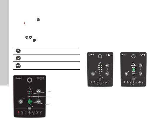
7. Control functions
7.1 Menu overview, SCALA2
TM06 3301 5114
Fig. 14 SCALA2 operating panel
SCALA2 Function
On/off
Increases the outlet pressure.
Decreases the outlet pressure.
Resets alarms.
Indicates the required outlet pressure.
Indicates that the pump has been stopped manually.
Indicates that the operating panel is locked.
7.1.1 Pressure indicator, SCALA2
The pressure indicator shows the required outlet pressure from 1.5 to 5.5 bars (22 to 80 psi) in 0.5 bar (7.5 psi) intervals.
The illustration below shows a pump set to 3 bar (44 psi) indicated by two green lights, and a pump set to 3.5 bar (51 psi) indicated by one green light.
Flashing green lights indicate that the pump has automatically lowered the pressure. See section
4.3.3 Self-learning setpoint.
|
|
|
|
|
|
|
|
TM06 4345 2015 |
Fig. 15 SCALA2 outlet pressure indication |
|
|||||||
|
|
BAR |
PSI |
Water colum |
kPa |
MPa |
|
|
|
|
|
|
[m] |
|
|
|
|
|
|
|
|
|
|
|
|
|
|
} |
5.5 |
80 |
55 |
550 |
0.55 |
|
|
|
|
5.0 |
73 |
50 |
500 |
0.50 |
|
|
|
} |
4.5 |
65 |
45 |
450 |
0.45 |
|
|
|
|
4.0 |
58 |
40 |
400 |
0.40 |
|
4117 |
|
|
3.0 |
44 |
30 |
300 |
0.30 |
|
|
|
|
3.5 |
51 |
35 |
350 |
0.35 |
|
|
} |
|
|
|
|
|
|
4187 |
|
} |
|
2.5 |
36 |
25 |
250 |
0.25 |
|
|
|
|
2.0 |
30 |
20 |
200 |
0.20 |
|
|
|
|
1.5 |
22 |
15 |
150 |
0.15 |
|
TM06 |
|
|
|
|
|
|
|
|
|
Fig. 16 Pressure indication table
14
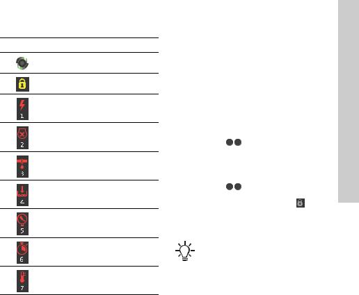
7.1.2 Indicator lights for SCALA2
Indications Description
Operating indications
The operating panel is locked.
Power supply failure
The pump is blocked, for instance the shaft seal has seized up.
Leakage in the system
Dry running or water shortage*
The maximum pressure has been exceeded or the setpoint cannot be reached.
The maximum runtime has been exceeded.
The temperature is outside the range.
*For fault number 4, dry running, the pump must be reset manually.
For fault number 4, water shortage, and the remaining faults, 1, 2, 3, 5, 6 and 7, the pump will reset whenever the cause has disappeared or been remedied. See section 8.3.3 Auto reset.
For further information about system status, see section 12. Fault finding the product.
8. Setting the product
The pump will remember the controller settings even if it is turned off.
8.1 Setting the outlet pressure
Adjust the outlet pressure by pressing 
 .
.
8.2Locking and unlocking the operating panel
The operating panel can be locked, which means that the buttons do not function and no settings can be changed accidentally.
How to lock the operating panel
1.Hold down the 
 buttons simultaneously for 3 seconds.
2.The operating panel is locked when  symbol lights up.
How to unlock the operating panel
1.Hold down the 
 buttons simultaneously for 3 seconds.
2. The operating panel is unlocked when symbol turns off.
8.3 Expert settings, SCALA2
Expert settings are for installers only.
The expert setting menu allows the installer to toggle between the following functions:
•self-learning
•auto reset
•anti cycling
•maximum continuous operating time.
English (GB)
15
English |
8.3.1 Accessing the expert settings |
|||||
Proceed as follows: |
||||||
1. |
Hold down the |
button for 5 seconds. |
||||
|
||||||
|
2. |
The |
|
symbol will start flashing to indicate that |
||
(GB) |
|
the |
expert settings are active. |
|||
The pressure indicator now acts as the expert menu. |
||||||
A flashing green diode is the cursor. Move the cursor |
||||||
|
using the |
buttons, and toggle the selection on |
||||
|
or off using the |
button. The diode for each setting |
||||
|
will light up when the setting is active. |
|||||
Move cursor up.
Move cursor down.
Toggle settings.
Self-learning
 Auto reset
Anti cycling
Maximum
 continuous
operating time |
4117 |
Exit expert menu |
TM06 4346 |
|
Fig. 17 Expert menu overview
8.3.2 Self-learning function
The factory setting for this function is "on".
On
If the pump cannot reach the user-defined pressure setpoint, the self-learning function will automatically adjust the setpoint.
The pump will lower the setpoint to either 4.5, 3.5 or 2.5 bar (65, 51 or 36 psi).
The self-learned setpoint is indicated on the operating panel by one flashing green light.
After every 24 hours, the pump will automatically attempt to revert to the original user-defined setpoint. If this is not possible, the pump will again return to the self-learned setpoint. The pump will continue to operate with the self-learning setpoint, until the user-defined setpoint can be reached.
Example:
The user-defined pressure is set to 5 bar (72 psi), indicated by constant green lights on the pressure indicator panel.
The pump is unable to reach this pressure due to negative pressure on the inlet side.
The self-learning function automatically adjusts the setpoint to 3.5 bar (51 psi), indicated by one flashing green light on the pressure indicator panel.
After 24 hours, the pump will automatically try to adjust the setpoint back to 5 bar (72 psi).
TM07 0078 4117 |
TM07 0079 4117 |
Fig. 18 User-defined setpoint (left) and self-learned setpoint (right)
How to reset the self-learned setpoint
1.You can manually reset the settings by pressing any button on the operating panel. The pump will immediately try to reach the original setpoint.
2.If the pump keeps reducing the setpoint due to self-learning, we recommend to reduce the setpoint manually on the operating panel.
Off
If you set the self-learning function to off and the pump is unable to reach the desired setpoint, the pump will show alarm 5.
16
Loading...