

Page 1
IMPORTANT INFORMATION
IMPORTANT INFORMATION KEEP FOR OPERATOR
IMPORTANT INFORMATION IMPORTANT INFORMATION
KEEP FOR OPERATOR IMPORTANT INFORMATION
KEEP FOR OPERATORKEEP FOR OPERATOR
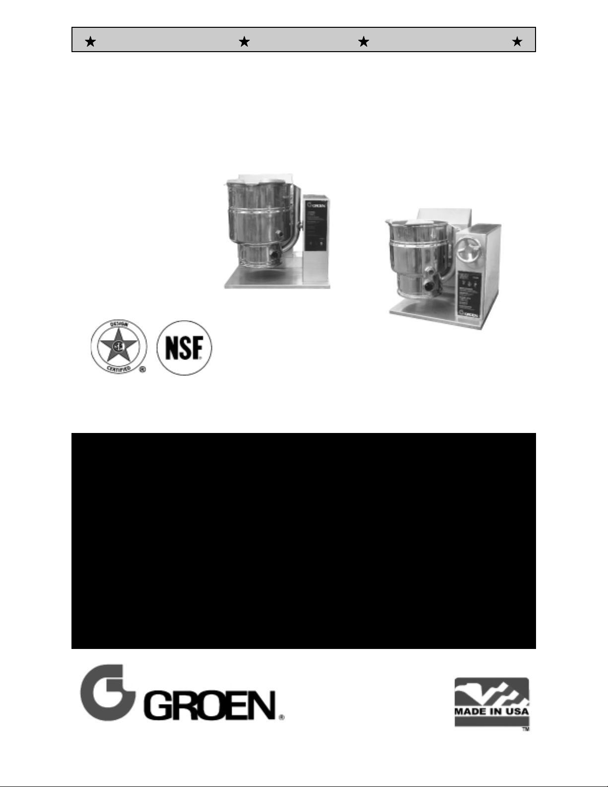
Models: TDH and TDHC
Steam Jacketed Kettle
Self-contained
Gas heated
Table Top Mounted
Crank-Tilting
Model TDH
IMPORTANT INFORMATION
IMPORTANT INFORMATIONIMPORTANT INFORMATION
HDT-MOLAUNAM ROTAREPO
CITSEMODB veR 077731 rebmuN traP
Model TDHC
THIS MANUAL MUST BE RETAINED FOR FUTURE REFERENCE. READ,
UNDERSTAND AND FOLLOW THE INSTRUCTIONS AND WARNINGS CONTAINED IN
THIS MANUAL.
FOR YOUR SAFETY
DO NOT STORE OR USE GASOLINE OR OTHER FLAMMABLE VAPORS AND
LIQUIDS IN THE VICINITY OF THIS OR ANY OTHER APPLIANCE.
POST IN A PROMINENT LOCATION
INSTRUCTIONS TO BE FOLLOWED IN THE EVENT USER SMELLS GAS. THIS
INFORMATION SHALL BE OBTAINED BY CONSULTING YOUR LOCAL GAS
SUPPLIER. AS A MINIMUM, TURN OFF THE GAS AND CALL YOUR GAS COMPANY
AND YOUR AUTHORIZED SERVICE AGENT. EVACUATE ALL PERSONNEL FROM
THE AREA.
WARNING
IMPROPER INSTALLATION, ADJUSTMENT, ALTERATION, SERVICE OR
MAINTENANCE CAN CAUSE PROPERTY DAMAGE, INJURY OR DEATH. READ THE
INSTALLATION, OPERATING AND MAINTENANCE INSTRUCTIONS THOROUGHLY
BEFORE INSTALLING OR SERVICING THIS EQUIPMENT.
Information contained in this document is
known to be current and accurate at the
time of printing/creation. Unified Brands
recommends referencing our product line
websites, unifiedbrands.net, for the most
updated product information and specifications.
Page 2

OM-TDH
IMPORTANT — READ FIRST — IMPORTANT
WARNING: FAILURE TO DISCONNECT POWER BEFORE SERVICING COULD RESULT IN
ELECTROCUTION AND DEATH.
WARNING: IMPROPER INSTALLATION, ADJUSTMENT, ALTERATION, SERVICE OR MAINTENANCE CAN
CAUSE PROPERTY DAMAGE, INJURY OR DEATH. READ THE INSTALLATION, OPERATING
AND MAINTENANCE INSTRUCTIONS THOROUGHLY BEFORE INSTALLING OR SERVICING
THIS EQUIPMENT.
WARNING: THE UNIT MUST BE INSTALLED BY PERSONNEL QUALIFIED TO WORK WITH GAS,
ELECTRICITY AND PLUMBING. UNIT MUST BE INSTALLED IN ACCORDANCE WITH ALL
APPLICABLE CODES.
WARNING: DO NOT ATTACH THE UNIT TO A TYPE “B” VENT. IT COULD CAUSE FIRE OR PROPERTY
DAMAGE.
WARNING: DO NOT CONNECT ANY PIPING TO THE PRESSURE RELIEF VALVE. IT MUST BE FREE TO
VENT STEAM AS NEEDED. TO AVOID BURNS FROM THE VENTED STEAM THE VALVE
DISCHARGE SHOULD POINT DOWNWARD.
DANGER: ELECTRICALLY GROUND THE UNIT AT THE TERMINAL PROVIDED. FAILURE TO GROUND
THE UNIT COULD RESULT IN ELECTROCUTION AND DEATH.
CAUTION: BE SURE ALL OPERATORS READ, UNDERSTAND AND FOLLOW THE OPERATING
INSTRUCTIONS, CAUTIONS AND SAFETY INSTRUCTIONS CONTAINED IN THIS MANUAL.
CAUTION: DO NOT OVERFILL THE KETTLE WHEN COOKING, HOLDING OR CLEANING. KEEP LIQUIDS
A MINIMUM OF 2-3" (5-8 CM) BELOW THE KETTLE BODY RIM TO ALLOW CLEARANCE FOR
STIRRING, BOILING AND SAFE TRANSFER OF PRODUCT.
CAUTION: KEEP FLOORS IN FRONT OF KETTLE WORK AREA CLEAN AND DRY. IF SPILLS OCCUR,
CLEAN IMMEDIATELY TO AVOID SLIPS OR FALLS.
WARNING: KEEP WATER AND SOLUTIONS OUT OF CONTROLS AND BURNERS. NEVER USE A HIGH
PRESSURE HOSE TO CLEAN KETTLE SURFACES.
CAUTION: MOST CLEANERS ARE HARMFUL TO THE SKIN, EYES, MUCOUS MEMBRANES AND
CLOTHING. TAKE PRECAUTIONS: WEAR RUBBER GLOVES, GOGGLES OR FACE SHIELD
AND PROTECTIVE CLOTHING. CAREFULLY READ WARNINGS AND FOLLOW DIRECTIONS
ON CLEANER LABELS .
WARNING: DO NOT STAND ON OR APPLY UNNECESSARY WEIGHT OR PRESSURE ON THE KETTLE
FRONT OR POURING LIP. THIS COULD RESULT IN THE OVERLOAD AND FAILURE OF THE
TILT MECHANISM, AND POSSIBLE SERIOUS INJURY AND BURNS TO THE OPERATOR AND
OTHERS.
NOTICE: NEVER LEAVE A SANITIZER IN CONTACT WITH STAINLESS STEEL SURFACES LONGER
THAN 10 MINUTES. LONGER CONTACT CAN CAUSE CORROSION.
WARNING: FAILURE TO PERIODICALLY CHECK PRESSURE RELIEF VALVE OPERATION COULD
RESULT IN PERSONAL INJURY AND/OR DAMAGE TO EQUIPMENT.
WARNING: WHEN TESTING, AVOID EXPOSURE TO THE STEAM BLOWING OUT OF THE PRESSURE
RELIEF VALVE. DIRECT CONTACT COULD RESULT IN SEVERE BURNS.
WARNING: TO AVOID INJURY, READ AND FOLLOW ALL PRECAUTIONS STATED ON THE LABEL OF
THE WATER TREATMENT COMPOUND.
WARNING: BEFORE REPLACING ANY PARTS, DISCONNECT THE UNIT FROM THE ELECTRIC POWER
SUPPLY AND CLOSE THE MAIN GAS VALVE. ALLOW FIVE MINUTES FOR GAS TO VENT.
CAUTION: USE OF ANY REPLACEMENT PARTS OTHER THAN THOSE SUPPLIED BY GROEN OR
AUTHORIZED DISTRIBUTORS CAN CAUSE INJURY TO THE OPERATOR AND DAMAGE TO
THE EQUIPMENT AND WILL VOID ALL WARRANTIES.
WARNING: KEEP AREA AROUND KETTLE FREE AND CLEAR OF ALL COMBUSTIBLE MATERIALS.
FAILURE TO DO SO COULD RESULT IN FIRE OR PROPERTY DAMAGE.
CAUTION: HEATING AN EMPTY KETTLE MAY CAUSE THE RELEASE OF STEAM FROM THE
PRESSURE RELIEF VALVE.
IMPORTANT: SERVICE PERFORMED BY OTHER THAN FACTORY AUTHORIZED PERSONNEL WILL VOID
ALL WARRANTIES.
2
Page 3

OM-TDH
Table of Contents
IMPORTANT OPERATOR WARNINGS..........................................2
EQUIPMENT DESCRIPTION ..................................................4
INSPECTION & UNPACKING .................................................5
INSTALLATION & INITIAL START-UP...........................................6
OPERATION...............................................................8
CLEANING ...............................................................11
SEQUENCE OF OPERATION ................................................12
MAINTENANCE ...........................................................13
COMPONENT REPLACEMENT...............................................15
TROUBLESHOOTING ......................................................18
PARTS LISTS.............................................................20
SCHEMATIC..............................................................32
SERVICE LOG ............................................................33
REFERENCES ............................................................34
3
Page 4
OM-TDH
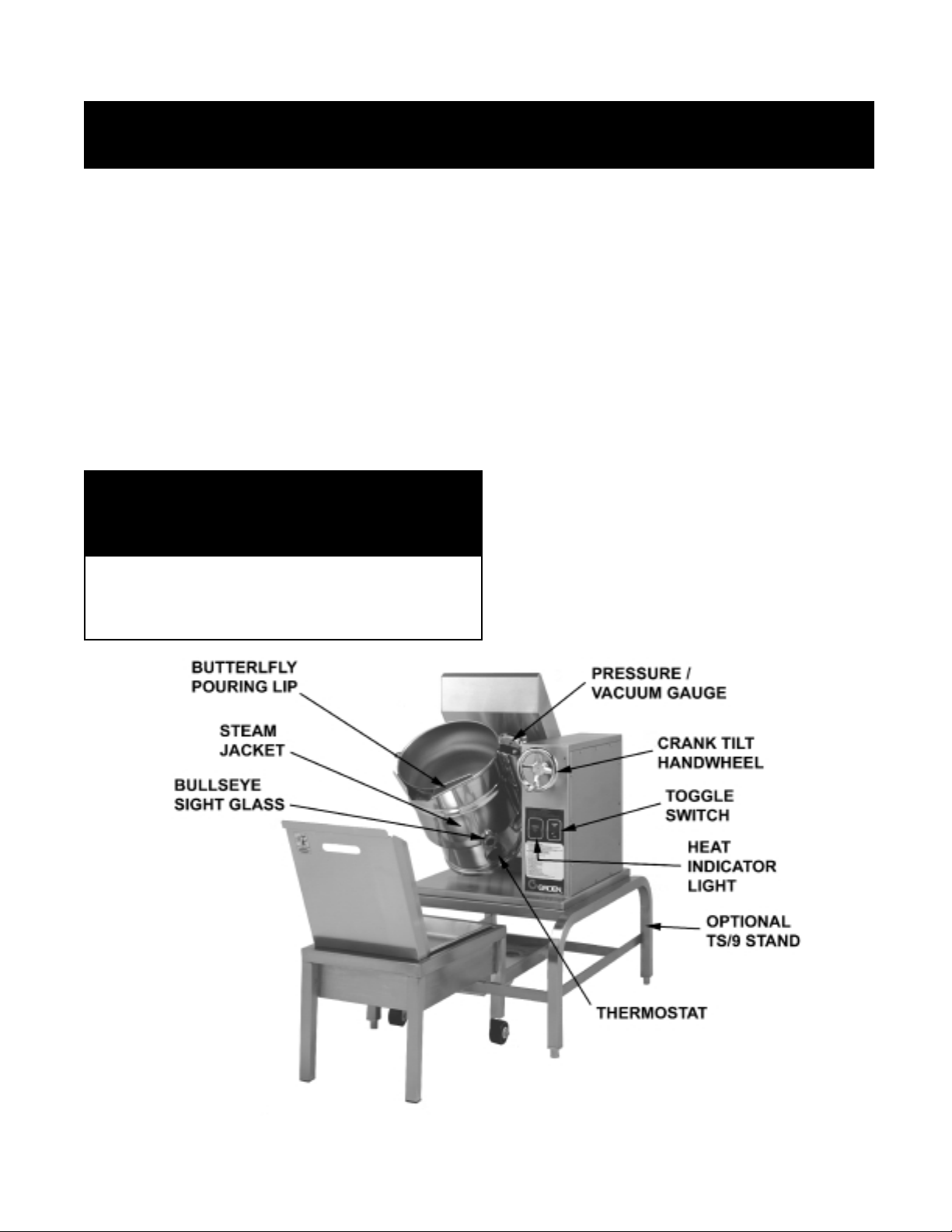
Equipment Description
Groen Models TDHC and TDH are stainless steel,
steam-jacketed, table top mounted kettles with a
self-contained, gas heated steam source. The TDHC
has a crank tilt hand wheel, and the TDH has a
handle that allows the operator to manually tilt the
kettle. The kettle body is welded into one solid piece
and furnished with a reinforced rim and welded-in
"butterfly" shaped pouring lip. The interior of the
kettle is polished to a 180 emery grit finish, and the
exterior is given a bright high buff finish.
The unit is A.S.M.E. shop inspected and registered
with the National Board for a design pressure of
50 PSIG.
The self-contained steam source is heated by
propane or natural gas and is equipped with
electronic ignition. Charged at the factory with
chemically pure water containing rust inhibitors, the
steam source provides kettle temperatures of 150ºF
to approximately 295
o
F.
KETTLE CHARACTERISTICS
Controls for the TDHC unit include a crank tilt
handwheel, thermostat, pressure gauge, pressure
relief valve, low water cut-off, On/Off switch, indicator
lamp, gas regulator valve, and water level sight
glass. Controls for the TDH are the same as the
above, with the exception of the crank tilt hand
wheel.
The gas supply shuts off automatically when the
kettle is tilted.
The unit must be specified for use with natural gas or
propane. For other gas types, consult factory.
Service connections are required for gas and 115V
electricity.
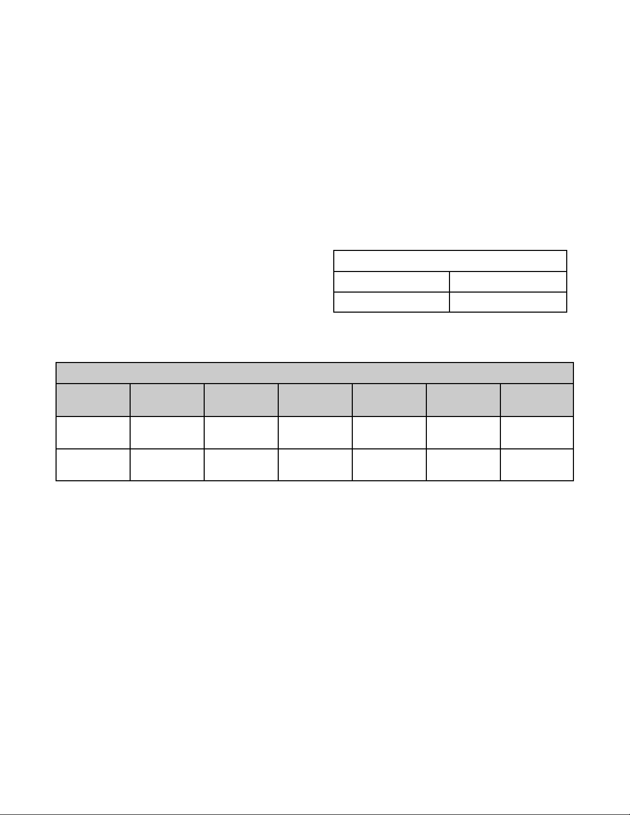
Firing Rate, BTU / Hour
TDHC-20, TDH-20 TDHC-40, TDH-40
31,000 BTU/hr 52,000 BTU/hr
Dimensions
Model
TDH-20
TDHC-20
TDH-40
TDHC-40
Options available include:
1. One-piece, Lift-off cover
(P/N 128003, 20 gallon
P/N 128002 40 gallon)
2. Holder for Lift-off Cover (P/N 133837)
3. Basket insert
(P/N 001159, 20 gallon
P/N 001161, 40 gallon)
Kettle
Capacity
20 Qt 18.9 # 6 Qt 5.7 # 14" 356 mm 11" 279 mm 28" 711 mm 24" 610 mm
40 Qt. 37.8 # 12 Qt 11.4 # 16½ 419 mm 14½”362 mm 28" 711 mm 26¾”679 mm
Jacket
Capacity
Kettle Body
Diameter
Kettle Body
Depth
4. Rice Strainer
(P/N 005187, 20 gallon
P/N 005186, 40 gallon)
5. Stand that supports the unit and holds a pan
in position for filling (Model TS-9)
6. Water fill swing faucet
7. 316 stainless steel interior
(must be indicated on initial order)
Base Width Base Depth
4
Page 5
Inspection & Unpacking
OM-TDH
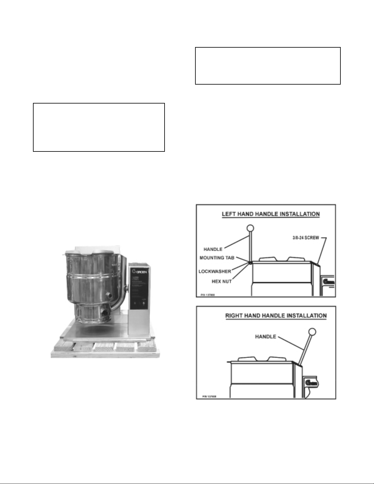
The unit arrives completely assembled, except for the
tilting handle on TDH models which is shipped inside
the kettle. The unit is strapped on a skid and in a
heavy carton. Inspect the carton carefully for
damage. Open the container and check the unit for
hidden damage. Report shipping damage or shipment
errors to the delivery agent.
CAUTION
SHIPPING STRAPS ARE UNDER TENSION
AND CAN SNAP BACK WHEN CUT. TAKE
CARE TO AVOID PERSONAL INJURY OR
DAMAGE TO THE UNIT BY STAPLES LEFT
IN THE WALLS OF THE CARTON.
Write down the model number, serial number, and
installation date for your unit at the top of the
Service Log on Page 30. Keep this manual with the
unit.
CAUTION
UNIT WEIGHS FROM 215 LBS. (98 KG) TO 240
LBS. (109 KG). INSTALLER SHOULD OBTAIN
HELP AS NEEDED TO LIFT THIS WEIGHT
SAFELY.
To remove the kettle from the box, cut any straps from
around the box. Detach the box sides from the skid.
Pull the box up off the unit, taking care to avoid
damage or injury from any staples left in the box
walls. When installation is to begin, cut the straps
holding the kettle on the skid, and lift the kettle
straight up off the skid. Examine the packing materials
to make sure no loose parts are discarded with the
materials. On TDH models, the tilting handle may be
screwed into its socket. Attach handle to the kettle on
left side or right side as shown below.
The TDH and TDHC are shipped from the factory
strapped on a pallet.
5
Page 6

OM-TDH
WARNING
THE KETTLE MUST BE INSTALLED BY PERSONNEL QUALIFIED TO WORK WITH GAS, ELECTRICITY AND
PLUMBING. IMPROPER INSTALLATION CAN CAUSE INJURY TO PERSONNEL AND/OR DAMAGE TO THE
EQUIPMENT.
Installation and Initial Start-Up
A. Installation
The TDHC kettle should be installed in a ventilated room
for efficient performance. Items which might obstruct or
restrict the flow of air for combustion and ventilation must
be removed. The area directly around the appliance
must be cleared of any combustible material.
1. Installation on combustible floors is allowed.
Minimum clearances between the unit and
combustible surfaces is as follows:
Minimum
distance from
combustible
walls
Left Side 1" 1"
Right Side 0”
Rear 1" 3" (for faucet bracket)
2. Groen recommends installation of the unit under a
vent hood. The base must be fastened to a working
surface or Groen Model TS-9 stand.
Recommended
12" - 16"
(for servicing)
6. The installation must conform with local codes or
the American National Standards Z223.1 - latest
edition National Fuel Gas Code. The kettle
should be installed in an adequately ventilated
room with provision for adequate air supply. The
best ventilation will employ a vent hood and
exhaust fan with no direct connection between
the vent duct and the kettle flue. DO NOT
obstruct the flue or vent duct after installation.
7. PRESSURE TEST WARNING
a) Test pressure exceeding ½ PSIG (3.45 kPa).
During pressure testing of the gas supply
piping system at pressures exceeding ½
PSIG, the appliance and its individual shutoff
valve must be disconnected from the gas
supply piping system.
b) Test pressure equal to or less than ½ PSIG
(3.45 kPa). During pressure testing of the
gas supply piping system at pressures equal
to or less than ½ PSIG, the kettle must be
isolated from the gas supply piping system
by closing its individual manual shutoff valve.
8. Adequate space for proper servicing and
operation is required. DO NOT block any air
intake spacings to the combustion chamber or
obstruct air flow.
3. Complete the piping to the gas service main using ½
inch IPS pipe or an approved equivalent.
WARNING
THIS UNIT IS FOR COMMERCIAL USE. DO NOT
USE HOME OR RESIDENTIAL GRADE GAS
CONNECTIONS. THEY DO NOT MEET GAS CODES
AND COULD BE HAZARDOUS.
4. Provide 115 VAC, 60 cycle, 1 phase, 1 AMP electric
service. Local codes and/or The National Electrical
Code should be observed in accordance with
ANSI/NFPA-70 latest edition. AN ELECTRICAL
GROUND IS REQUIRED. The electrical schematic
is located on the inside of the service panel and in
this manual.
5. Electrical connection to the unit must be water
resistant sealtite conduit type or equal and utilize the
water resistant conduit fitting provided on the unit.
9. After the kettle has been connected to the gas
supply, check all gas joints for leaks. A soap
solution or other suitable gas leak detector
should be used. Do not use flame when
checking for leaks.
10. Once the unit is anchored to a mounting surface,
apply a small bead of silicone caulk around the
perimeter of the kettle base and seal the joint.
11. Make sure the water level is correct in the jacket,
by confirming that the level is near the middle of
the sight glass. If the water level is low, follow
the instructions in Jacket Filling and Water
Treatment in the Maintenance section of this
manual.
12. Check to be sure that the open end of the elbow
on the outlet of the pressure relief valve is
directed downward. Be sure to read and follow
the instructions on the attached pressure relief
valve tag.
6
Page 7
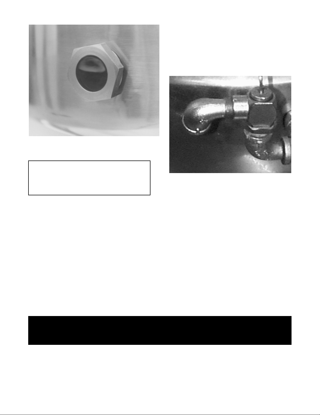
Correct Water Level
B. Initial Start-Up
IMPORTANT:
BE SURE ALL OPERATORS READ,
UNDERSTAND AND FOLLOW THE OPERATING
INSTRUCTIONS, CAUTIONS, AND SAFETY
INSTRUCTIONS CONTAINED IN THIS MANUAL.
OM-TDH
5. To turn off the unit, follow “To Stop Kettle
Heating” in the Operation Section of this manual.
If the kettle functions as described, it is ready for
use. If the unit does not operate as designed,
contact an authorized Groen Service Agent.
Make sure that the open end of the elbow on the
pressure relief valve is directed downward.
After the kettle has been installed, the installer should
test to ensure that it is operating correctly.
1. Remove literature and packing materials from inside
and outside of the unit.
2. Add water to the kettle to a depth of at least
one inch.
3. Make sure the supplies of gas and electric power
are on.
4. Follow the “To Start Kettle Heating” instructions in
the Operation section of this manual. Begin heating
the water at the highest thermostat setting. The
indicator light should come on and heating should
continue until the water boils.
WARNING
DO NOT STAND ON OR APPLY UNNECESSARY WEIGHT OR PRESSURE ON THE KETTLE FRONT OR
POURING LIP. THIS COULD RESULT IN THE OVERLOAD AND FAILURE OF THE TILT MECHANISM, AND
POSSIBLE SERIOUS INJURY AND BURNS TO THE OPERATOR AND OTHERS.
7
Page 8
OM-TDH
Operation
WARNING
ANY POTENTIAL USER OF THE EQUIPMENT MUST BE TRAINED IN SAFE
AND CORRECT OPERATING PROCEDURES
A. Controls
Operator controls for the TDH and TDHC kettles are:
1. Manual gas valve which controls the supply of gas from
the main to the unit.
2. On-Off (toggle) switch. This switch turns the control
circuit power supply on or off.
3. Thermostat dial, which turns the thermostat on or off,
and sets the kettle operating temperature.
4. Crank tilt handwheel (TDHC ONLY) which controls
kettle movement.
B. Operating Instructions
WARNING
KEEP AREA AROUND KETTLE FREE AND CLEAR OF
ALL COMBUSTIBLE MATERIALS. .DO NOT ATTEMPT
TO LIGHT ANY BURNER WITH A FLAME.
CAUTION
HEATING AN EMPTY KETTLE MAY CAUSE THE
RELEASE OF STEAM FROM THE PRESSURE RELIEF
VALVE.
1. To Start Kettle Heating
a. CHECK THE WATER LEVEL IN THE
JACKET EVERY DAY. The level should be
in the middle of the sight glass. If the water
level is low, see Jacket Filling in the
Maintenance section of this manual.
b. Check the pressure/vacuum gauge. If the
gauge does not show 20 to 30 inches of
vacuum (i.e., a reading of 20 to 30 below
zero), see Jacket Vacuum in the
Maintenance section of this manual.
c. DO NOT attempt to light any burner with a
flame.
d. Open the main supply gas valve (handle in
line with the pipe).
e. Turn the toggle switch to ON.
f. Turn the thermostat to the desired heat
setting.
The TDHC is shown on on the optional TS/9 stand.
8
Page 9
1. To Stop Kettle Heating
a. Turn the thermostat dial to OFF.
b. Turn the toggle switch OFF.
c. For a prolonged shut-down:
1. Follow the procedure above.
2. Turn the manual gas valve OFF (handle at
right angle to gas line).
3. Disconnect the unit’s electrical power.
3. To Relight Kettle
a Close main gas supply valve.
b. Set on-off switch to OFF.
c. Set thermostat to OFF.
d. Wait five minutes, then proceed as directed under
To Start Kettle Heating.
OM-TDH
CAUTION
DO NOT OVERFILL THE KETTLE WHEN
COOKING, HOLDING OR CLEANING. KEEP
LIQUIDS 2-3” (5-8 cm) BELOW THE KETTLE
RIM TO ALLOW CLEARANCE FOR STIRRING,
BOILING PRODUCT AND SAFE TRANSFER.
WARNING
WHEN TILTING KETTLE:
1) WEAR PROTECTIVE OVEN MITT AND
PROTECTIVE APRON.
2) USE DEEP CONTAINER TO CONTAIN AND
MINIMIZE PRODUCT SPLASHING.
3) PLACE CONTAINER ON STABLE, FLAT
SURFACE, CLOSE TO THE KETTLE.
4) STAND AWAY FROM POUR PATH OF HOT
CONTENTS.
5) POUR SLOWLY, KEEP CONTROL OF
KETTLE, AND RETURN KETTLE BODY
SLOWLY TO UPRIGHT POSITION AFTER
CONTAINER IS FILLED OR TRANSFER IS
COMPLETE.
6) DO NOT OVERFILL CONTAINER. AVOID
DIRECT SKIN CONTACT WITH HOT
CONTAINER AND ITS CONTENTS.
4. If electric power fails, do not attempt to operate
the unit. When power is restored, proceed as
directed in To Start Kettle Heating.
5. To Transfer Product or Empty Kettle:
TDHC Kettles:
The kettle body is tilted using the crank tilt handwheel.
Turning the crank clockwise tilts the kettle body;
counter-clockwise returns it to an upright position. The
kettle body will remain in any tilted position.
TDH Kettles:
The kettle is designed to be tilted in a controlled
manner. Grasp the insulated plastic ball firmly.
Maintain a firm grip on handle when tilting, keeping
kettle body in a tilted position or SLOWLY returning the
kettle body to an upright position.
WARNING
AVOID ALL DIRECT CONTACT WITH HOT FOOD OR
WATER IN THE KETTLE. DIRECT CONTACT COULD
RESULT IN SEVERE BURNS.
TAKE CARE TO AVOID CONTACT WITH HOT KETTLE
BODY OR HOT PRODUCT, WHEN ADDING
INGREDIENTS, STIRRING OR TRANSFERRING
PRODUCT TO ANOTHER CONTAINER.
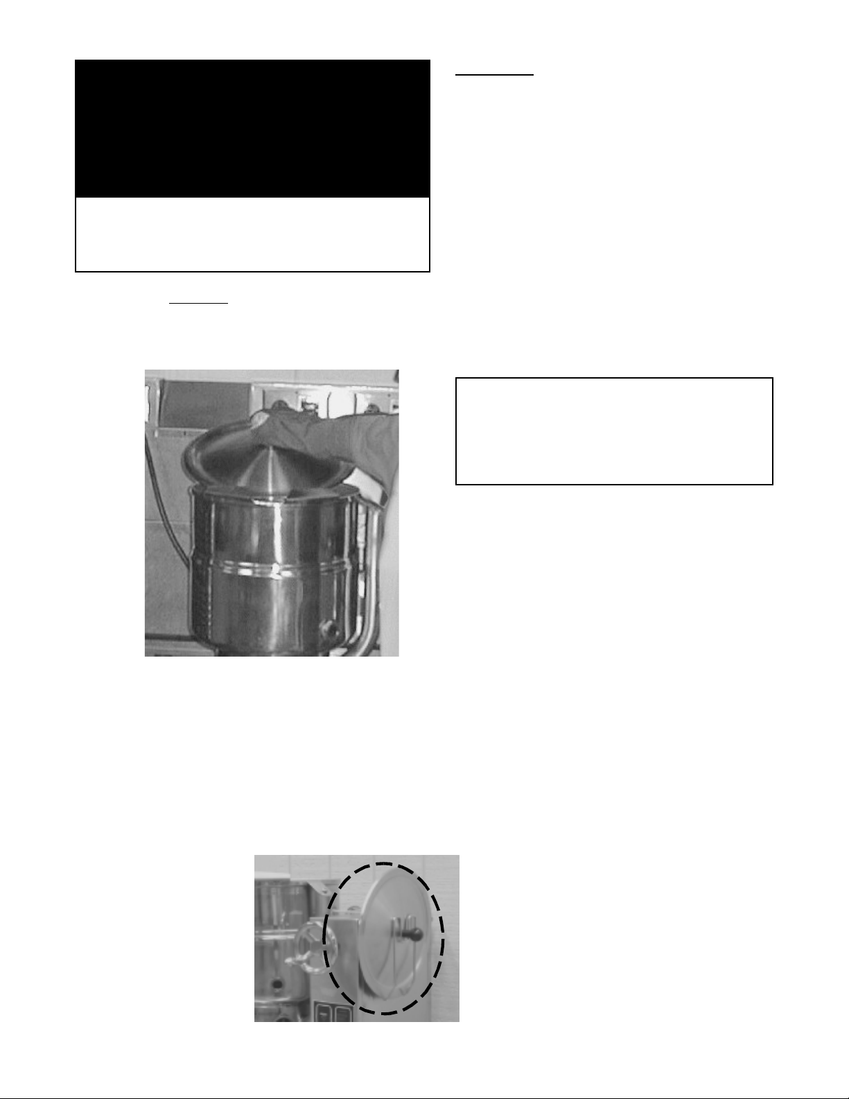
6. Use of Common Accessories
Lift-Off Cover
a. As with stock pot cooking, an optional
lift off cover will speed up the heating of
water and food products. A cover helps
retain heat in the cooking vessel and
reduces the amount of heat and
humidity released into the kitchen. Use
of a cover can reduce some product
cook times and help maintain the
temperature, color and texture of
products being held or simmered for
extended periods.
b. Make sure the plastic ball handle is
secure on the lift off cover before using.
ALWAYS use the plastic handle to
place or remove cover from the kettle.
Wear protective oven mitts and a
protective apron.
c. When putting the cover on the kettle,
position it on top of kettle rim, with its
flat edge facing the pouring lip.
d. When removing cover:
1) Firmly grasp plastic handle
9
Page 10
OM-TDH
WARNING
AVOID ALL DIRECT CONTACT WITH HOT
SURFACES. DIRECT SKIN CONTACT COULD
RESULT IN SEVERE BURNS.
AVOID ALL DIRECT CONTACT WITH HOT FOOD OR
WATER IN THE KETTLE. DIRECT CONTACT COULD
RESULT IN SEVERE BURNS.
CAUTION
DO NOT TILT KETTLE BODY WITH COVER OR
BASKET INSERT IN PLACE. COVER MAY SLIDE
OFF, CAUSING INJURY TO OPERATOR.
2) Lift rear edge
(3-5 cm) to allow any steam and water vapor
to escape the cooking vessel. Wait 2-3
seconds.
(farthest from operator) 1-2”
Basket Insert
a. An optional kettle basket insert can assist in
cooking water-boiled products including
eggs, potatoes, vegetables, shell fish, pasta
and rice. The nylon mesh liner must be
used when cooking product smaller than the
mesh size of the basket, which is
approximately 1/4” (6 mm). This includes
rice and small pasta shapes.
b. Tips For Use.
1) Allow for the water displacement of the
basket and product to be cooked. This
may mean only filling the kettle half full
of water. Test the basket and product
displacement with the kettle OFF, and
with cold water in the kettle.
CAUTION
DO NOT OVERFILL THE KETTLE WHEN
COOKING, HOLDING OR CLEANING. KEEP
LIQUIDS A MINIMUM OF 2-3” (5-8 cm) BELOW
THE RIM TO ALLOW FOR STIRRING, BOILING
AND SAFE PRODUCT TRANSFER.
Lift the rear of the lid first.
3) Tilt cover to 45-60° angle and allow any hot
condensate or product to roll off cover back
into kettle.
4) Remove cover, ensuring that any remaining
hot condensate or product does not drip on
operator, floor or work surfaces.
5) Place cover on safe, flat, sanitary, out-of-theway surface, or
return to kettle
rim. Cover
may also be
placed in the
optional holder
(P/N 133837)
for cover as
shown in the
photograph.
2) Load basket on a level, stable work
surface.
3) Lift the loaded basket with both hands.
Get help from another person if the
basket is too heavy for safe handling.
Then slowly lower product into kettle.
4) When removing basket with cooked
product, lift basket straight up, ensuring
bottom of basket clears the rim and
pouring lip of the kettle. Wear protective
oven mitts and protective apron.
5) Allow hot water to fully drain from
product, before moving basket away
from the kettle. Do not rest kettle
basket on kettle rim or pouring lip. If
basket is too heavy for individual to lift
and safely move, get help from another
person. Remove product immediately
from basket into another container,
being sure to avoid contact with hot
product and hot basket or place basket
with food on stable, flat surface, setting
it inside a solid steamer or bake pan, to
catch any remaining hot water draining
from product.
10
Page 11
Cleaning
OM-TDH
1. Suggested Cleaning Supplies:
a. Cleaner, such as Klenzade HC-10 or HC-32
from ECOLAB, Inc.
b. Kettle brushes in good condition.
c. Sanitizer such as Klenzade XY-12.
d. Film remover such as Klenzade LC
2. Precautions
Before any cleaning operation, shut off the kettle
by turning the thermostat dial to "OFF", and shut
off all electrical power to the unit at a remote
switch, such as the circuit breaker.
WARNING
KEEP WATER AND SOLUTIONS OUT OF
CONTROLS AND BURNERS. DO NOT USE A
HIGH PRESSURE HOSE TO CLEAN THE
CONTROL CONSOLE, ELECTRICAL
CONNECTIONS, ETC.
3. Procedure
a. Clean food contact surfaces as soon as
possible after use, preferably while the kettle
is still warm. If the unit is in continuous use,
clean and sanitize inside and outside at least
once every 12 hours.
d. Rinse the kettle thoroughly with hot water.
Then drain completely.
CAUTION
MOST CLEANERS ARE HARMFUL TO THE SKIN,
EYES, MUCOUS MEMBRANES AND CLOTHING.
PRECAUTIONS SHOULD BE TAKEN TO WEAR
RUBBER GLOVES, GOGGLES OR FACE SHIELD
AND PROTECTIVE CLOTHING. CAREFULLY READ
THE WARNINGS AND FOLLOW LABEL
DIRECTIONS.
e. As part of the daily cleaning program, clean
all inside and outside surfaces that may have
been soiled. Remember to check such parts
as the underside of the cover, control
housing, etc.
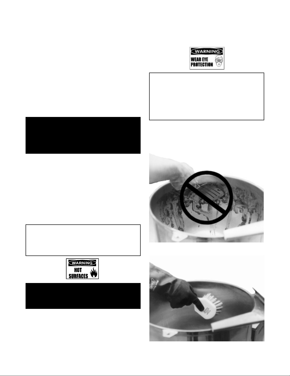
b. Scrape and flush out large amounts of food
residues. Be careful not to scratch the kettle
with metal implements.
CAUTION
NEVER LEAVE A CHLORINE SANITIZER IN
CONTACT WITH STAINLESS STEEL SURFACES
LONGER THAN 30 MINUTES. LONGER CONTACT
CAN CAUSE CORROSION.
WARNING
AVOID DIRECT CONTACT WITH HOT SURFACES.
DIRECT SKIN CONTACT COULD RESULT IN
SEVERE BURNS.
c. Prepare a solution of the detergent/cleaning
compound as instructed by the supplier.
Clean the unit thoroughly. A cloth moistened
with cleaning solution can be used to clean
controls, housing, electrical conduit, etc.
Scrapers, steel wool or metal implements will
harm the kettle surface.
Use a sponge, cloth or plastic brush to clean the
kettle.
11
Page 12

OM-TDH
f. To remove burned-on foods, use a brush,
sponge, cloth, plastic or rubber scraper, or
plastic wool along with the cleaning solution.
To reduce effort required in washing, let the
detergent solution sit in the kettle for a few
minutes and soak into the residue. Do NOT
use abrasive materials or metal tools that
might scratch the surface. Scratches make
the surface harder to clean and provide
places for bacteria to grow. Do not use steel
wool, which will leave particles in the surface
and cause eventual corrosion and pitting.
g. The outside of the unit may be cleaned with a
warm water (100°F or less) spray. Do not
use a high pressure spray.
h. The outside of the unit may be polished with
a recognized stainless steel cleaner like
“Zepper” from Zep Manufacturing Company.
i. When the equipment needs to be sanitized,
use a sanitizing solution equivalent to one
that supplies 200 parts per million chlorine.
Obtain advice on the best sanitizing agent
from your supplier of sanitizing products.
Following the supplier’s instructions, apply the
sanitizing agent after the unit has been
cleaned and drained. Rinse off the sanitizer
thoroughly.
j. It is recommended that the unit be sanitized
just before use.
k. Clean the kettle thoroughly. If there is
difficulty removing mineral deposits or a film
left by hard water or food residues, then
use a de-liming agent, such as Groen
De-limer De-Scaler (Part Number 114800),
Lime- Away from ECOLAB or an equivalent,
following manufacturer directions.
l. Rinse and drain the unit thoroughly before
further use.
m. If especially difficult cleaning problems
persist, contact your cleaning product
supplier for assistance. The supplier has a
trained technical staff with laboratory facilities
to serve you.
Sequence of Operation
The following “action-reaction” outline is provided to
help understand how the equipment works.
1. When the power switch is turned on, it starts
the spark igniter and opens the automatic valve
for the pilot burner. The spark ignites a pilot
flame, which heats the sensor. The sensor then
sends a signal to turn off the spark. The flame
thereafter acts as a standing pilot until the
power is turned off.
2. If the pilot flame is not sensed within 90
seconds after spark begins, a timer shuts down
the entire operation. To attempt a second trial
for ignition, turn off the power switch. Check
the gas supply valves and wait five minutes
before trying again by switching power on. If
you cannot establish a pilot flame in four tries,
close all valves, turn off the power, and contact
an authorized Groen Service Agency.
3. When the operator sets a temperature on the
thermostat, it causes the automatic valve to
admit gas to the main burner, where it is ignited
by the pilot flame. When the kettle reaches the
set temperature, the thermostat switch opens.
This stops the signal to the gas control valve
and shuts off gas to the main burner. The pilot
flame remains lit. When the kettle cools below
the set temperature, the thermostat switch
closes and starts another cycle. On and off
cycling continues and maintains the kettle at the
desired temperature. This action is indicated by
the Heat indicator light.
The kettle has the following safety features in
addition to the 90-second ignition timer:
1. Low water cutoff relay that will shut off gas
supplies to all burners until the jacket water
level is corrected.
2. High limit pressure switch, set to open at about
43 PSI and to shut down the burners until jacket
pressure is decreased.
3. Pop pressure relief valve, which will release
steam if jacket pressure exceeds 50 PSI.
4. Tilt switch, which shuts off all burners when the
kettle is tilted.
5. Gas pressure regulator built into the gas control
valve.
12
Page 13

Maintenance
NOTICE: Contact an authorized Groen Service Agent when repairs are required.
OM-TDH
A Maintenance & Service Log is provided at the back
of this manual with the warranty information. Each
time maintenance is performed on your Groen kettle,
enter the date on which the work was done, what
was done, and who did it. Keep this manual on file
and available for operators to use.
Periodic inspection will minimize equipment down
time and increase the efficiency of operation. The
following points should be checked:
1. Jacket Vacuum/
Removing Air From Jacket
(By Operator)
Every day, while the kettle is cold, read the
pressure/ vacuum gauge. A positive reading or
a negative reading between zero and 20"
vacuum on the pressure/ vacuum gauge
indicates excess air in the jacket. Air in the
jacket slows kettle heating and can prevent the
kettle from reaching operating temperature. To
remove air:
a. Start the kettle. (See the Operation
section).
2. Pressure Relief Valve
(By Operator)
At least twice a month, test the pressure relief
valve. Test the valve with the kettle operating at
15 PSI (105 kPa), by holding the test ring for at
least five seconds. Then release the ring and
permit the valve to snap shut. If the ring does
not activate, if there is no discharge, or if the
valve leaks, stop using the kettle immediately
and contact a authorized Groen service
representative.
WARNING
AVOID EXPOSURE TO THE STEAM BLOWING
OUT OF THE PRESSURE RELIEF VALVE.
SEVERE BURNS CAN RESULT ON EXPOSED
SKIN.
FAILURE TO CHECK PRESSURE RELIEF VALVE
OPERATION PERIODICALLY COULD RESULT IN
PERSONAL INJURY AND/OR DAMAGE TO
EQUIPMENT.
3. Grease / Lubrication
b. Make sure the elbow on the outlet of the
pressure relief valve is turned so that
escaping steam is directed down toward the
floor (see photo on page 7).
c. When the pressure/vacuum gauge reaches
a positive pressure reading of 5 PSI,
release trapped air by lifting the pressure
relief valve ring for about one second.
Repeat this step, then let the valve ring
snap closed, so the valve will seat properly
and not leak.
For TDH Models: At least twice a year, grease
the two trunnion bearings. The bearings are
located within the kettle support housing.
Remove the access panels from the support
housing with a screwdriver to gain access to the
grease fittings. Use a lithium-based, multipurpose grease. When the access panels are
removed, the mounting bolts for the trunnion
bearings and tilt switch can also be checked for
tightness. When finished, reassemble access
panels to support housing.
For TDHC Models:
fitted for proper lubrication of moving parts.
Since the gears do not run in oil, periodic
lubrication with grease is essential. Frequency
of lubrication depends on operating conditions,
but should occur at least once every six months.
Groen recommends the use of a Number Two
grade LGI lithium grease. Add grease through
the Zerk fittings on the gear housing until grease
flows out of the bearings around the trunnion
shaft. Place a liberal amount of grease on the
gear to cover the arc that is in contact with the
worm gear.
The gear housing has been
The pressure gauge should show a
vacuum of 20 to 30 inches when the
kettle is cold.
CAUTION
KEEP GREASE AWAY FROM ELECTRICAL
PARTS.
13
Page 14

OM-TDH
4. Jacket Filling
5. Water Treatment
Every day, before you turn on the unit, make
sure the water level is approximately in the
center of the water gauge glass. The jacket
was filled at the factory with the proper amount
of treated water, and is air-tight, but over time
steam may be vented and water lost.
From time to time, you may need to restore the
water to its proper level. The procedure for
adding water follows.
a. If you are replacing water lost as steam,
use distilled water. Do not use tap water.
If you are replacing treated water that was
drained from the jacket, prepare more
treated water as directed below.
WARNING
TO AVOID INJURY, READ AND FOLLOW ALL
PRECAUTIONS STATED ON THE LABEL OF
THE WATER TREATMENT COMPOUND.
a. Fill a mixing container with the amount of
water required. Use only distilled water.
Model
TDH-20, TDHC-20 20 Qt 18.9 # 6 Qt 5.7 #
TDH-40, TDHC-40 40 Qt 37.8 # 12 Qt 11.4 #
b. Hang a strip of pH test paper on the rim of
the container, with about 1 inch of the strip
below the surface of the water. If there is a
problem distinguishing color, use a pH
meter.
c. Stir the water continuously, while you
slowly add water treatment compound until
a color between indicating a pH of 10.5 and
11.5 is reached. (Shown on the pH test kit
chart.) Judge the pH by frequently
comparing the test strip with the color chart
provided in the pH test kit.
Kettle
Capacity
Jacket
Capacity
The pressure relief valve and fill plug are located
directly behind the pressure/vacuum gauge.
b. Allow the kettle to cool completely.
Remove the pipe plug from the jacket fill
assembly. Pour in the distilled or treated
water. Using a funnel will help you in this
process. Hold the pressure relief valve
open while you pour, to let air escape from
the jacket. Continue adding water until the
water level rises to the center of the round
sight glass.
c. Air that gets into the jacket during the filling
operation must be removed, because it will
make heating less efficient. Follow the
procedure in Jacket Vacuum/Removing
Air From Jacket above, to restore a
negative pressure reading.
d. Use a measuring cup to add the compound
so that you may record the exact amount
used.
e. The amount may be used again, if the
same water sources and compound are
used in the future. However, it is best to
check the pH each time treated water is
prepared.
WARNING
USE OF ANY REPLACEMENT PARTS OTHER
THAN THOSE SUPPLIED BY GROEN OR THEIR
AUTHORIZED DISTRIBUTORS CAN CAUSE
INJURY TO THE OPERATOR AND DAMAGE TO
THE EQUIPMENT AND WILL VOID ALL
WARRANTIES.
CAUTION
INSURE ELECTRICAL POWER IS REMOVED
AND THE GAS IS TURNED OFF AT THE
SHUTOFF VALVE PRIOR TO PERFORMING ANY
MAINTENANCE ON THIS KETTLE.
WARNING
THIS KETTLE IS DESIGNED TO BE WATER
RESISTANT. FAILURE TO FOLLOW PROPER
MAINTENANCE PROCEDURES MAY VOID THE
WARRANTY.
14
Page 15

Component Replacement
OM-TDH
WARNING
BEFORE REPLACING ANY PARTS,
DISCONNECT THE UNIT FROM THE ELECTRIC
POWER SUPPLY.
All internal wiring is marked as shown on the
circuit schematic drawings. Be sure that new
components are wired in the same manner as
the old components.
1. Removal of right hand side cover
a. Remove 14 phillips head screws
(12 screws for the TDH-20).
b. Remove side cover.
CAUTION
FAILURE TO INSTALL ALL 14 COVER SCREWS
MAY VOID WARRANTY.
2. Installation of right hand side cover
Install all 14 phillips head screws (12 screws for
the TDH-20) to maintain water resistance of
electronics compartment and torque to 10 in-lbs.
NOTE:
WATER RESISTANT. ALL SEALS AND
GASKETS MUST
FUNCTIONAL UPON COMPLETION OF ANY
SERVICE. FAILURE TO DO SO WILL VOID THE
WARRANTY.
THIS KETTLE IS DESIGNED TO BE
BE IN PLACE AND
5. Removal of burner “ON” indicator
light
a. Remove right hand side cover (see Section
#1 above).
a. Remove blue and green wires from light.
b. Remove nut from light on inside of electrical
box.
c. Pull light out being careful not to lose rubber
grommet.
6. Installation of burner “ON” indicator
light
a. Install light from outside of front panel.
b. From inside of panel install rubber grommet
then nut.
c. Tighten nut hand tight plus ½ to ¾ turn.
d. Reattach blue and green wires.
e. Reinstall right hand side cover as stated in
Section #2 above.
7. Removal of transformer
3. Removal of ON/OFF switch
a. Remove right hand side cover (see Section
#1 above).
a. Remove black and red wires from switch.
b. Unscrew nut from outside of switch.
c. Remove switch from inside being carful not
to lose rubber gasket.
4. Installation of ON/OFF switch
a. Insert switch through hole in the front panel
from the inside.
b. Insure the rubber gasket is inserted between
switch and front panel.
c. Install knurled nut on switch and tighten to
hand tight plus ½ to ¾ turn.
d. Reinstall red and black wires on switch.
e. Reinstall right hand side cover (see Section
#2 above).
a. Remove right hand side cover (see Section
#1 above).
b. Unplug wires from transformer terminals:
two red wires, one green wire, and one
white wire.
c. Remove both ¼" mounting screws.
8. Installation of transformer
a. Mount transformer with two ¼" mounting
screws.
b. Install two red wires on bottom terminals,
the white wire on the top right terminal and
the green wire on the top left terminal.
c. Reinstall right hand side cover as stated in
Section #2 above.
9. Removal of water level control board
a. Remove right hand side cover (see Section
#1 above).
b. Remove wires from control board.
c. Squeeze plastic stand-offs behind board
and pull board off.
15
Page 16

OM-TDH
10. Installation of water level control
board
f. Reinstall right hand side cover as stated in
Section #2 above.
a. Align control board and install two ¼"
mounting screws.
b. Install wires in the following order:
i. Blue wire bottom right
ii. Red wire second from bottom right
iii. Green wire upper right
iv. Yellow wire bottom left
v. Double red wire top left
c. Reinstall right hand side cover as stated in
Section #2 above.
11. To remove Honeywell gas control
module
a. Remove right hand side cover (see Section
#1 above).
b. Remove wires from module terminals.
c. Remove the four ¼" mounting screws.
12. Installation of Honeywell gas
control module
a. Align module and install the four ¼"
mounting screws.
b. Reinstall wiring in the following order,
starting on the left with terminal 1:
i. Red (MV)
ii. Yellow (MV/PV)
iii. Black (PV)
iv. Green 24v from burner
v. Green 24v ground
vi. Red 24v
vii. Terminal 9 Spark ignition lead
c. Reinstall right hand side cover as stated in
Section #2 above.
13. Removal of tilt micro switch
a. Tilt kettle 90°.
b. Remove the right hand side cover (see
Section #1 above).
c. Remove blue and white wires from switch.
d. Remove the two mounting screws.
e. Remove switch.
15. Removal of gas valve
a. Turn off gas supply to the kettle.
b. Remove side cover (see #1 above).
c. Disconnect electrical power from the kettle.
d. Disconnect wiring from the gas valve.
e. Disconnect valve to burner tube using a ½”
in-line wrench.
f. Remove 90° elbow.
g. Remove burner cover by removing three
screws on cover flange and two hex head
bolts located inside electrical box.
h. Disconnect union on gas piping located
under burner cover.
i. Remove gas valve.
16. Installation of gas valve
a. Remove piping from old valve and install
on new valve.
b. Reconnect the union under burner cover.
c. Reinstall burner cover.
d. Reinstall gas piping removed in step 19.
e. Insure rubber grommet is properly installed.
f. Reconnect electrical wiring in the following
order:
i. Black to PV
ii. Yellow to MV-PV
iii. Blue to MV (TH)
g. Reinstall right hand side cover as stated in
Section #2 above.
17. Removal of thermostat
a. Remove thermostat knob by pulling straight
out.
b. Remove the two mounting screws.
c. Remove thermostat shroud.
d. Tilt kettle to 90°.
e. Remove bottom cover.
f. Remove blue and red wires from
thermostat.
g. Unscrew temperature bulb from kettle body
being careful not to damage adjacent
pressure switch.
14. Installation of tilt micro switch
a. Tilt kettle 90°.
b. Align switch with mounting holes behind
bracket with paddle facing forward.
c. Install both mounting screws and nuts.
d. Replace both the blue and white wires on
the bottom two tabs.
e. Insure kettle actuates switch when it is
returned to the upright position.
18. Installation of thermostat
a. Tilt kettle 90°.
b. Install thermostat gasket in opening in skirt.
c. Install second gasket on thermostat and
align the screw holes with the holes in the
gasket.
d. Place the thermostat through the hole in the
kettle skirt and align screw holes.
e. Replace plastic spacer on thermostat shaft.
16
Page 17

f. Replace the stainless knob shroud and
align holes.
g. Start both screws but do not tighten.
h. Put Teflon tape on the screw threads of the
thermostat bulb and insert into bottom of
kettle. Tighten hand tight plus one turn.
i. Install bottom cover on skirt. Tighten
screws and gasket to 10-12 in-lb torque.
j. Turn the kettle upright and tighten the two
thermostat mounting screws.
k. Install knob by pushing straight on shaft.
l. If the knob appears loose, remove and
gently spread the two prongs of the shaft
and reinstall knob.
m. Check water level.
n. Remove air from jacket.
Thermostat and Gasket Installation Detail
OM-TDH
20. Installation of water probe
a. Apply Teflon tape to probe threads.
b. Screw probe into kettle jacket and torque to
150 in-lbs.
c. Attach yellow wire to probe.
d. Reinstall bottom cover.
e. Check water level.
f. Remove air from jacket.
21. Removal of pressure switch
a. Tilt kettle a full 90°.
b. Remove bottom cover.
c. Unplug red and white wires from switch.
d. Using a 9/16 open end wrench, carefully
unscrew the pressure switch from the 90°
elbow.
22. Installation of pressure switch
a. Hand start the pressure switch into the 90°
elbow.
b. Using a 9/16 wrench, tighten the switch to
90 in-lbs.
c. Reattach the red and white wires to the
switch.
d. Reinstall bottom cover.
e. Check water level.
f. Remove air from jacket.
19. Removal of water level probe
a. Tilt kettle 90° and remove bottom cover.
b. Remove yellow wire from probe.
c. Unscrew probe from kettle jacket.
17
Page 18

OM-TDH
Troubleshooting
Your Groen kettle is designed to operate smoothly and efficiently if properly maintained. However, the following is
a list of checks to make in the event of a problem. Wiring diagrams are furnished inside the service panel and in
this manual. If an item on the list is followed by <<<<, the work should be done by a qualified service
representative.
WARNING
BEFORE REPLACING ANY PARTS, DISCONNECT THE UNIT FROM THE ELECTRIC POWER SUPPLY
AND CLOSE THE MAIN GAS VALVE. ALLOW FIVE MINUTES FOR UNBURNED GAS TO VENT.
CAUTION
USE OF ANY REPLACEMENT PARTS OTHER THAN THOSE SUPPLIED BY GROEN OR THEIR AUTHORIZED
DISTRIBUTOR CAN CAUSE INJURY TO THE OPERATOR AND DAMAGE TO THE EQUIPMENT AND WILL
VOID ALL WARRANTIES.
SYMPTOM WHO WHAT TO CHECK
Kettle is hard to tilt.
(TDHC ONLY).
Kettle continues heating after
it reaches desired
temperature.
Kettle stops heating before it
reaches the desired
temperature.
Pressure Relief Valve pops
open
Burners will not light. User a. That the main gas supply valve is open. (handle is in line with gas
System does not produce a
spark
Auth
Service
Rep Only
User a. Thermostat dial setting.
Auth
Service
Rep Only
User a. Thermostat dial setting.
Auth
Service
Rep Only
User a. For air in the jacket. See Jacket Vacuum / Removing Air From
Auth
Service
Rep Only
Auth
Service
Rep Only
Auth
Service
Rep Only
<<<< indicates items which must be performed by an authorized technician.
a. Gears for foreign materials, and lubrication. <
b. Gears for alignment. <
c. Worm gears or broken gears. <
b. Thermostat calibration.<
c. Thermostat operation. The thermostat should click when the dial is
rotated to settings above and below the temperature of the kettle.<
b. Thermostat calibration.<
c. Thermostat operation. The thermostat should click when the dial is
rotated to settings above and below the temperature of the kettle.<
Jacket in the Maintenance section.
b. Thermostat dial setting.
c. For defective thermostat. The thermostat should click when the dial
is rotated to settings above and below the temperature of the kettle.
If defective, replace.<
d. For defective pressure relief valve. If the valve pops at pressures
below 49 PSI, replace.<
pipe).
b. Gas supply to the building.
c. That the kettle body is horizontal.
d. Thermostat operation. The thermostat should click when the dial is
rotated to settings above and below the temperature of the kettle.<
e. Momentary switch is being properly actuated.<
a. Thermostat, and close the contacts if they are open <
b. AC voltage between terminals on secondary side of transformer. If
it is not 24 Volt, replace the transformer <
c. That the high tension cable is firmly attached and in good condition.
If cracked or brittle, replace.<
d. Pilot electric ceramic for crack or break.<
e. Pilot spark gap. Regap.<
18
Page 19

SYMPTOM WHO WHAT TO CHECK
Spark is present but the pilot
will not light.
Pilot lights, but main burner
will not come on and spark
does not stay on.
Pilot lights, but main burner
will not come on, the spark
stays on.
Main burner comes on but
will not stay on.
Auth
Service
Rep Only
Auth
Service
Rep Only
Auth
Service
Rep Only
Auth
Service
Rep Only
OM-TDH
<<<< indicates items which must be performed by an authorized technician.
a. That the pilot valve is securely connected to terminals.<
b. For 24 VAC at terminals PV and PV/MV. If 24V is not present,
replace the ignition control module.<
b. That gas pressure is at least 3.5" W.C.(8.7818 b).<
c. For gas at the pilot. If it is not flowing:
(1) Check the pilot gas line for kinks and obstructions.<
(2) Clean orifice, if necessary.<
(3) Check magnetic operator for pilot valve on gas valve. Repair
or replace as necessary.<
d. That the pilot spark gap is located in the pilot gas stream. If not,
adjust or replace the pilot burner.<
e. For drafts. Shield the pilot burner, if necessary.<
a. For 24 V between terminals PV and PV/MV. If 24V is not present,
replace the ignition control module.<
b. That gas pressure is at least 3.5" W.C.(8.7818 b).<
c. Electrical connections of the main valve to terminals, to assure that
they are securely attached. Check magnetic operator for pilot valve
on gas valve. Repair or replace as necessary.<
a. Check for bad burner ground. If necessary, repair with high
temperature wire.<
b. Pilot burner ceramic insulator for cracks.<
c. That cable is not grounded out. If it is, correct the ground-out
condition or replace cable.<
d. For proper gas pressure.<
e. Clean pilot assembly, or replace if necessary.<
f. Tighten all mechanical and electrical connections.<
g. If the pilot flame is weak, increase pilot orifice size.<
h. Replace ignition control module.<
a. Check burner ground for bad wire or connection. Replace if
necessary with high temperature wire.<
b. Check for low gas supply pressure. If necessary, replace ignition
control module.<
19
Page 20

OM-TDH
Parts List
To order parts, contact your Groen Authorized Service Agency. Supply the model designation, part description, part number, quantity, and where applicable, voltage .
Key Description Part No. Key Description Part No. Key Description Part No.
1 Knob, Thermostat 002868 7 Gauge 084208 12 Switch, Pressure (Not Shown) 096963
2 Gasket, Thermostat 123585 8 Kettle Body Assy 137733 13 Electrode, Water Level (Not Shown) 074623
3 Thermostat 012313 9 Glass, Site Round 108554 14 Shaft, Handle 018963
4 Gas Valve, Nat. Gas 098443 10 Valve, Pressure Relief 50 PSI 097005 15 Ring, ½" 012692
5 Gas Valve, Manual Shut Off 098458 11 Guard, Thermostat 114830 16 Ball, Red 012691
6 Valve, 1/4" Swing, Check 096915
20
Page 21

OM-TDH
Parts List
To order parts, contact your Groen Authorized Service Agency. Supply the model designation, part description,
part number, quantity, and, where applicable, voltage.
Key Description Part No. Key Description Part No.
1 Nipple, 3/8" NPT x 2" 005679 5 Tube, Pilot 135487
2 Union, 3/8" NPT 005686 6
Manifold, TDH-20
3
Manifold, TDH-40
4 Pilot 097024 8 Orifice SEE TABLE BELOW
PART # 8
TDH-20
TDHC-20
TDH-40
TDHC-40
137757
137056
# of
Natural Gas Propane Gas Altitude
Orifices
8 137758 137756 0 - 2000 ft
12 135543 137756 0 - 2000 ft
Pilot Orifice Spud Natural Gas
Pilot Orifice Spud Propane Gas
7 Fitting, Compression 90 (Not Shown) 004584
098648
098647
21
Page 22

OM-TDH
Parts List
TDH Units Only
To order parts, contact your Groen Authorized Service Agency. Supply the model designation, part description,
part number, quantity, and, where applicable, voltage.
22
Page 23

OM-TDH
Parts List
TDH Units Only
To order parts, contact your Groen Authorized Service Agency. Supply the model designation, part description,
part number, quantity, and, where applicable, voltage.
Key Description Part No. Key Description Part No.
1 Weldment, Base TDHC-40 137060 19 Seal Trunion 137005
2 Weldment, Pedestal TDHC-40 124735 20 Plate, Shroud Weld ASM (TDH-20) 137700
3 Weldment, Base Support TDHC-40 124729 20 Plate, Shroud Weld ASM (TDH-40) 137380
4 Washer Lock ½" S.S. 005657 21 Gasket, 3/8" Thk x ½" Wide, 6" Center 137588
5 Screw, Hex HD 1/2-13 x 1 1/4" 005623 Cut 1/4" Hole ( Not Shown)
6 Nut Hexagon 1/2"-13 005603 22 E-Ring, 1.875" Dia. 138357
7 Screw Truss HD 1/4-20 x ½ S.S. 012700 23 Light Indicator Red 24VAC 116383
8 Asm, Cabinet Weld 137725 24 Gasket Switch TDHC-40 137435
9 Shroud Burner Weld Asm, TDHC-40 135526 25 Gasket Lamp TDHC-40 137434
10 Shield, Pilot, TDHC-40 135524 26 Faucet Bracket 137738
11 Burner Bracket Weld Asm. 135527 27 Grommet 7/8" ID x 1-5/8" OD 007400
12 Bracket, Burner Support 137353 28 Cover, Cabinet TDHC-40 137004
13 Screw, Truss HD #8-32 x 3/8" 005764 29 Screw, 10-32 x ½" Combi Head 137766
14 Screw, Hex HD 1/4"-20 x 1/2" 005608 30 Switch SPST ON/OFF 006904
15 Washer Lock 1/4" 005655 31 Connector Straight 3/8" Sealtite 001669
16 Screw Hex HD Cap 1/4"-20 x 1-1/2 005649 32 Harness Asm TDHC-40 137006
17 Nut Hexagon Keps 1/4"-20 012940 33 Harness Asm High Voltage TDCH-40 137456
18 Plate Shroud Weld Asm. 137680 34 Strap Cable TY-RAP 011093
35 Sealant RTV #732, Grey 001711
23
Page 24

OM-TDH
Parts List
TDHC Units Only
24
Page 25

OM-TDH
Parts List
TDHC Units Only
To order parts, contact your Groen Authorized Service Agency. Supply the model designation, part description,
part number, quantity, and, where applicable, voltage.
Key Description Part No. Key Description Part No.
1 Weldment, Base TDHC-40 137060 21 Gasket, 3/8" Thk x ½" Wide, 6" Center 137588
2 Weldment, Pedestal TDHC-40 124735 Cut 1/4" Hole ( Not Shown)
3 Weldment, Base Support TDHC-40 124729 22 E-Ring, 1.875" Dia. 138357
4 Washer Lock ½" S.S. 005657 23 Light Indicator Red 24VAC 116383
5 Screw, Hex HD 1/2-13 x 1 1/4" 005623 24 Gasket Switch TDHC-40 137435
6 Nut Hexagon 1/2"-13 005603 25 Gasket Lamp TDHC-40 137434
7 Screw Truss HD 1/4-20 x ½ S.S. 012700 26 Faucet Bracket 137738
8 Asm, Cabinet Weld 137725 27 Grommet 7/8" ID x 1-5/8" OD 007400
9 Shroud Burner Weld Asm, TDHC-40 135526 28 Cover, Cabinet TDHC-40 137004
10 Shield, Pilot, TDHC-40 135524 29 Screw, 10-32 x ½" Combi Head 137766
11 Burner Bracket Weld Asm. 135527 30 Switch SPST ON/OFF 006904
12 Bracket, Burner Support 137353 31 Connector Straight 3/8" Sealtite 001669
13 Screw, Truss HD #8-32 x 3/8" 005764 32 Harness Asm TDHC-40 137006
14 Screw, Hex HD 1/4"-20 x 1/2" 005608 33 Harness Asm High Voltage TDCH-40 137456
15 Washer Lock 1/4" 005655 34 Strap Cable TY-RAP 011093
16 Screw Hex HD Cap 1/4"-20 x 1-1/2 005649 35 Sealant RTV #732, Grey 001711
17 Nut Hexagon Keps 1/4"-20 012940 36 O-Ring #018 138359
18 Plate Shroud Weld Asm. 137680 37 E-Ring, 1.00" 138356
19 Seal Trunion 137005 38 Collar, Shaft Seal, .750" 138354
20 Plate, Shroud Weld ASM (TDH-20) 137700 39 Seal, Shaft 1.00" 136088
20 Plate, Shroud Weld ASM (TDH-40) 137380
25
Page 26

OM-TDH
Parts List
(TDH Units Only)
To order parts, contact your Groen Authorized Service Agency. Supply the model designation, part description,
part number, quantity, and, where applicable, voltage.
Key Description Part No. Key Description Part No.
1 Spacer, Pillow Block 137692 7 Washer Flat 3/8" 005830
2 Pillow Block 002989 8 Nut Hex 3/8"-16 005619
3 Stop, Manual Tilt, TDH-40 137697 9 Nut Hex 5/16"-18 005602
4 Key, 1/4 Sq x .5" Lg, TDH-20 137746 10 Screw Set Socket 086617
5 Collar Set 1-1/2" ID x 2-1/4" OD x 3/4" Thk 003118 11 Screw Set Socket 003400
6 Screw Hex HD Cap 3/8"-16 x 1-1/2" 005615 12 Screw Hex HD Cap 5/16"-18 x 1" 005613
26
Page 27

OM-TDH
Parts List
(TDHC Units Only)
To order parts, contact your Groen Authorized Service Agency. Supply the model designation, part description,
part number, quantity, and, where applicable, voltage.
Key Description Part No. Key Description Part No.
1 Assembly, Gear Carrier 124741 8 Assembly, Handwheel 124719
2 Shaft, Worm 122374 9 Pin, Roll 1/4" x 1.63 Lg. 128036
3 Gear, Worm 128001 10 Washer, Flat 3/8" 005830
4 Assembly, Gear Sector 128028 11 Washer, Lock 3/8" 005618
5 Assembly, Bearing Block 128021 12 Screw, 3/8-16 x 1" Hex HD 005612
6 Key, 1/4 Sq x 1" Lg. 122371 13 Pin, Roll 1/4" x 1.25" Lg. 012614
7 Retaining Ring 1.500 124764
27
Page 28

OM-TDH
Parts List
TDH and TDHC
To order parts, contact your Groen Authorized Service Agency.
Supply the model designation, part description, part number, quantity, and, where applicable, voltage and phase.
Key Description Part No. Key Description Part No.
1 Pressure Switch 096963 5 Cover (NOT SHOWN) 003141
2 Thermostat 012313 6 Gasket, Bottom Cover (NOT SHOWN) 137969
3 Water Level Electrode 015589 7 Screw, ¼-20 x 1 ½ (NOT SHOWN) 012597
4 Bracket 137736 8 Gasket, Bottom Cover Screw (NOT SHOWN) 137968
28
Page 29

OM-TDH
Parts List
To order parts, contact your Groen Authorized Service Agency. Supply the model designation, part description,
part number, quantity, and, where applicable, voltage and phase.
Key Description Part No. Key Description Part No.
1 Gauge, Compound Pressure w/Dual 084208 3 Assy, Water Fill Sub 137438
2 Valve, Pressure Relief 50 PSI 097005 4 Elbow, ½” NPT 90 Deg Street Blk 096905
29
Page 30

OM-TDH
Parts List
To order parts, contact your Groen Authorized Service Agency. Supply the model designation, part description,
part number, quantity, and, where applicable, voltage.
Key Description Part No. Key Description Part No.
1 Elec. Mounting Bracket 137489 9 P. C. Board Mounting Post 099901
2 Control, Water Level, 24 V 122192
10 Screw, 8 x 3/8 lg. hex slot
(for #5 and #17)
3 Micro Switch 002982 11 Screw #8-32 x 1-1/4 Rnd Head (for #4) 005056
4 Terminal Block, two pole 003887 12 Screw, Round Head 4-40 x 3/4 lg. (for
#3)
5 Ignition Module 085153 13 Barrier Insulation (for #3) 003490
6 Fuse, Holder, Type 3 AG 077854 14 Washer shakeproof Lock, #6 (for #3) 005715
7 Fuse, three Amp Type 3 AG 077853 15 Nut, Hex 4-40 (for #3) 003121
8 Screw, 6-32 x 3/8 lg (for #6) 009697 16 Transformer, 20 VA 120 V 137487
069789
003122
30
Page 31

Schematic
TDH & TDHC
OM-TDH
115 VOLT
SUPPLY
31
Page 32

OM-TDH
Service Log
Model No. __________________________________ Purchased From _____________________________
Serial No. __________________________________ Location
____________________________________
Date Purchased _____________________________ Date Installed _______________________________
Purchase Order No. __________________________ For Service Call _____________________________
Date Service Performed Performed By
32
Page 33

References
KLENZADE SALES CENTER
ECOLAB. Inc.
370 Wabasha
St. Paul, Minnesota 55102
800/352-5326 or 612/293-2233
NATIONAL FIRE PROTECTION ASSOCIATION
60 Battery March Park
Quincy, Massachusetts 02269
NFPA/54 Installation of Gas Appliances & Gas Piping
NFPA/70 The National Electrical Code
NATIONAL SANITATION FOUNDATION
3475 Plymouth Rd.
Ann Arbor, Michigan 48106
UNDERWRITERS LABORATORIES, INC.
333 Pfingsten Road
Northbrook, Illinois 60062
OM-TDH
ZEP MANUFACTURING CO.
1310-T Seaboard Industrial Blvd.
Atlanta, Georgia 30318
33
Page 34

1055 Mendell Davis Drive
Jackson, MS 39272
Phone 601 372-3903
Fax 601 373-9587
www.groen.com
OM-TDH (Revised 10/02)
Part Number 137770 Rev B
 Loading...