

Page 1
OPERATOR MANUAL
IMPORTANT INFORMATION, KEEP FOR OPERATOR
This manual provides information for:
MODEL NGB/3E
& CNGB/3-24
STEAM BOILERS
· Gas Heat
· 200,000 BTU/hr Firing Rate
· 3.7 Effective Boiler Horsepower
READ, UNDERSTAND AND FOLLOW THE INSTRUCTIONS AND
WARNINGS CONTAINED IN THIS MANUAL.
.ECNEREFER ERUTUF ROF DENIATER EB TSUM LAUNAM SIHT
WARNING / FOR YOUR SAFETY
and liquids in the vicinity of this or any other appliance.
POST IN A PROMINENT LOCATION
Instructions to be followed in the event user smells
gas. This information shall be obtained by consulting
your local gas supplier. As a minimum, turn off the gas
and call your gas company and your authorized service
agent. Evacuate all personnel from the area.
WARNING
Improper installation, adjustment, alteration, service
or maintenance can cause property damage, injury or
death. Read the installation, operating and maintenance
instructions thoroughly before installing or servicing this
equipment.
NOTIFY CARRIER OF DAMAGE AT ONCE
It is the responsibility of the consignee to inspect the container upon receipt of
same and to determine the possibility of any damage, including concealed damage. Unified Brands suggests that if you are suspicious of damage to make a
notation on the delivery receipt. It will be the responsibility of the consignee to file
a claim with the carrier. We recommend that you do so at once.
Manufacture Service/Questions 888-994-7636.
Information contained in this document is known to be current and accurate at the time
of printing/creation. Unified Brands recommends referencing our product line websites,
unifiedbrands.net, for the most updated product information and specifications.
PART NUMBER 121003 REV D (07/14)
1055 Mendell Davis Drive
Jackson, MS 39272
888-994-7636, fax 888-864-7636
unifiedbrands.net
Page 2

IMPORTANT - READ FIRST - IMPORTANT
WARNING: THE UNIT MUST BE INSTALLED BY PERSONNEL QUALIFIED TO WORK WITH GAS, ELECTRICITY AND
PLUMBING. IMPROPER INSTALLATION CAN CAUSE INJURY TO PERSONNEL AND/OR DAMAGE TO
THE EQUIPMENT. THE UNIT MUST BE INSTALLED IN ACCORDANCE WITH APPLICABLE CODES.
NOTICE: LEVEL THE UNIT BEFORE USE. IT MAY BE PITCHED SLIGHTLY TO THE REAR.
CAUTION: AN ELECTRICAL GROUND IS REQUIRED.
CAUTION: DO NOT LOCATE THE BOILER CABINET DIRECTLY OVER A FLOOR DRAIN OR FLOOR SINK. HUMIDITY
OR WATER FROM A DRAIN WILL DAMAGE ELECTRICAL PARTS OF THE UNIT.
WARNING: TO AVOID DAMAGE OR INJURY, FOLLOW THE WIRING DIAGRAM EXACTLY WHEN CONNECTING A
UNIT.
CAUTION: DO NOT USE PLASTIC PIPE. DRAIN MUST BE RATED FOR STEAM AND BOILING WATER.
WARNING: DO NOT CONNECT THE DRAIN DIRECTLY TO A BUILDING DRAIN.
WARNING: BLOCKING THE DRAIN MAY BE HAZARDOUS.
IMPORTANT: IMPROPER DRAIN CONNECTION WILL VOID WARRANTY.
WARNING: ALLOW COOKING CHAMBERS TO COOL BEFORE CLEANING.
WARNING: CAREFULLY READ THE WARNINGS AND FOLLOW THE DIRECTIONS ON THE LABEL OF EACH
CLEANING AGENT. USE SAFETY GLASSES AND RUBBER GLOVES AS RECOMMENDED BY DELIMING
AGENT MANUFACTURER.
WARNING: DO NOT MIX DE-LIMING AGENTS (ACID) AND DE-GREASERS (ALKALI) IN THE STEAM GENERATOR
OR ON THE COOKING CHAMBER WALLS.
NOTICE: DO NOT USE A CLEANING OR DE-LIMING AGENT THAT CONTAINS ANY SULFAMIC ACID OR
ANY CHLORIDE, INCLUDING HYDROCHLORIC ACID (HCL). IF THE CHLORIDE CONTENT OF ANY
PRODUCT IS UNCLEAR, CONSULT THE MANUFACTURER.
NOTICE: DO NOT USE A DE-GREASER THAT CONTAINS POTASSIUM HYDROXIDE OR SODIUM HYDROXIDE OR
THAT IS HIGHLY ALKALINE.
WARNING: USE OF ANY REPLACEMENT PARTS OTHER THAN THOSE SUPPLIED BY GROEN OR THEIR
AUTHORIZED DISTRIBUTOR VOIDS ALL WARRANTIES AND CAN CAUSE BODILY INJURY TO THE
OPERATOR AND DAMAGE THE EQUIPMENT. SERVICE PERFORMED BY OTHER THAN FACTORYAUTHORIZED PERSONNEL WILL VOID ALL WARRANTIES.
WARNING: HIGH VOLTAGE EXISTS INSIDE CONTROL COMPARTMENTS. DISCONNECT POWER SOURCE BEFORE
SERVICING. FAILURE TO DO SO CAN RESULT IN SERIOUS INJURY OR DEATH.
WARNING: DO NOT EXPOSE SKIN TO ESCAPING STEAM. SEVERE BURNS CAN RESULT.
CAUTION: MAKING ANY ELECTRICAL OR MECHANICAL CHANGE IN THE UNIT WITHOUT PRIOR WRITTEN
APPROVAL FROM GROEN ENGINEERING WILL VOID ALL WARRANTIES.
WARNING: ALL POTENTIAL USERS OF THE EQUIPMENT SHOULD BE TRAINED IN SAFE AND CORRECT
OPERATING PROCEDURES.
WARNING: DO NOT OPERATE THE UNIT UNLESS ALL REMOVABLE PANELS (RIGHT, LEFT, FRONT AND REAR)
HAVE BEEN PROPERLY INSTALLED.
2 OM-NGB/3
Page 3

Table of Contents
Important Operator Warnings ...................................................... page 2
References..................................................................................... page 3
Equipment Description.................................................................. page 4
Water Quality and Treatment ......................................................... page 5
Installation .................................................................................. page 6-7
Initial Start-Up................................................................................ page 8
Operation ...................................................................................... page 9
Sequence of Operation ................................................................ page 10
Cleaning.................................................................................. page 11-12
Maintenance................................................................................. page 13
Troubleshooting...................................................................... page 14-15
Electrical Schematic .................................................................... page 19
Service Log ................................................................................. page 20
References
NATIONAL FIRE PROTECTION ASSOCIATION
60 Batterymarch Park
Quincy, Massachusetts 02269
NFPA/70 The National Electrical Code
NFPA/54 Installation of Gas Appliances & Piping
NFPA/96 Ventilating Hoods
NSF INTERNATIONAL
789 N. Dixboro Rd.
P.O. Box 130140
Ann Arbor, Michigan 48113
CSA INTERNATIONAL
8501 Ease Pleasant Valley Road
Cleveland, Ohio 44131
AMERICAN NATIONAL STANDARDS INSTITUTE
1403 Broadway, New York, New York 10018
Z21.30 Installation of Gas Appliances & Piping
Z223.1 (latest edition) National Fuel Gas Code
OM-NGB/3 3
Page 4
Equipment Description
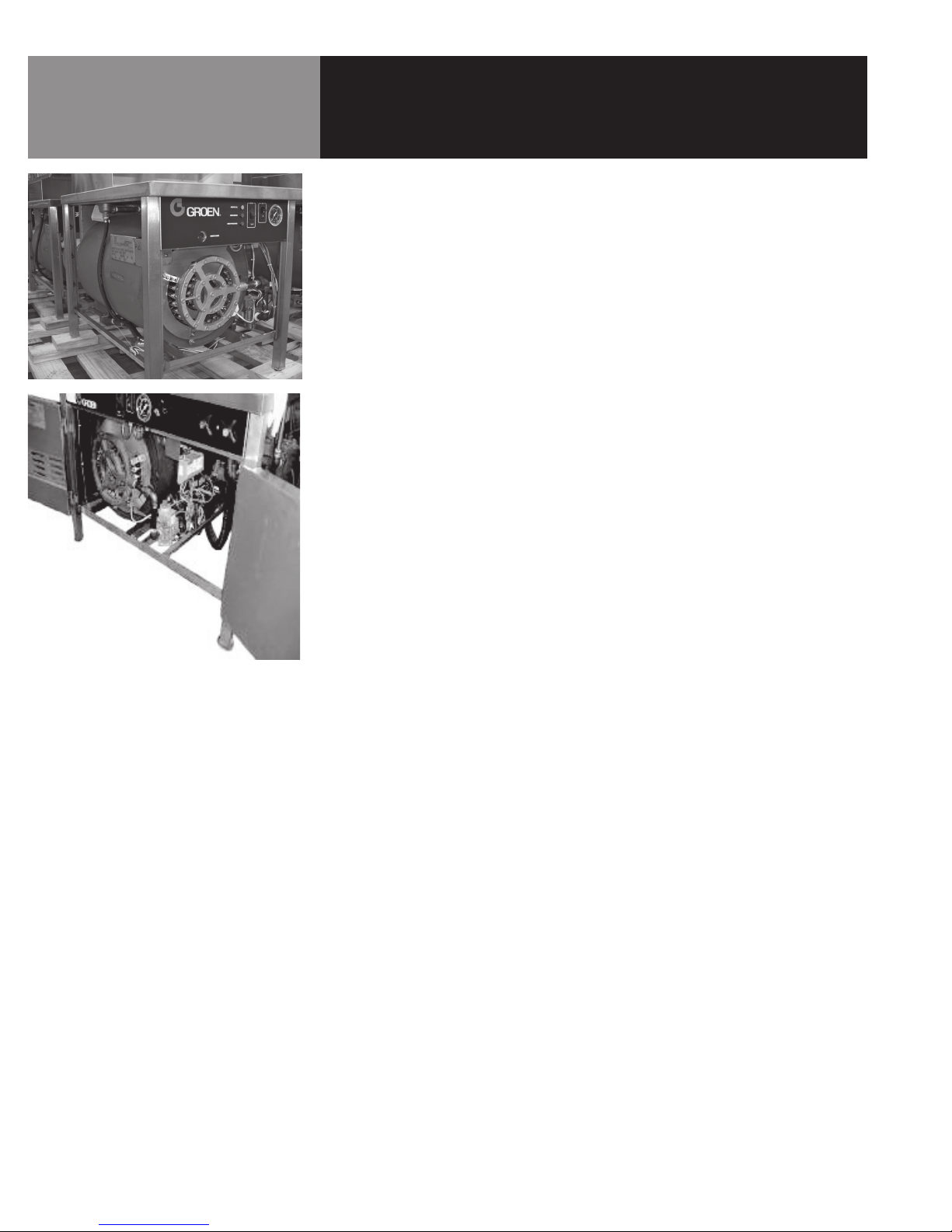
Groen NGB/3E and CNGB/3-24 steam boilers generate low pressure steam for use
with HyPlus cabinet mounted steamers and steam jacketed kettles. Both models
use a spark ignition system. The boiler is housed in a stainless steel cabinet. Various
combinations of steam-operated kettles and steamers can be mounted on the top.
The boiler is small enough to fit in a 24-1/8” wide by 34-3/16” deep by 29-3/16” tall
(maximum) cabinet.
The boiler is constructed of 1/4” thick steel, which is certified by the American Society
of Mechanical Engineers (ASME) for pressure vessels. All welds are hydrostatically
tested. The boiler is also equipped with required instruments, fittings, and
controls per CSD-1 (Controls and Safety Devices for automatically fired boilers).
Heat transfer fins inside the combustion chamber add to the unit’s high efficiency.
Both units are rated as 60% efficient or better, with a firing rate of 200,000 BTU per
hour using natural or propane gas. Energy output is 120,000 BTU per hour, with an
effective boiler horsepower of 3.7.
4 OM-NGB/3
Page 5

Water Quality & Treatment
REDUCE SCALE PROBLEMS BY USING
AND MAINTAINING A WATER SOFTENER
FOR YOUR STEAMER!
It is essential to supply the steam generator with water that will not form scale or cause
corrosion. Even though the steam generator is engineered to minimize scale formation
and the effects of corrosion, their development depends on the quality of your water
and the number of hours per day you operate the equipment.
Most water supplies are full of minerals and chemicals which are not suitable for use in
a steam generator.
Water quality varies from state to state and city to city. It is necessary that you know
and understand the quality of the water you are using. Your water utility can tell you
about the minerals and chemicals in your water. The water going to the steam generator should be within these guidelines
Water Pressure 30-60 psi
PH 7 to 9
Hardness less than 60 ppm
TDS 30 to 60 ppm
Chlorine and Chloramine less than 0.1 ppm
Total Chloride less than 30 ppm
Silica less than 12 ppm
Undissolved Solids less than 5 microns
1. Do not rely on unproven water treatments which are sold for scale prevention or
scale removal. They don’t always work. The best way to prevent scale is to supply
the purest possible water (30 - 60 ppm TDS).
2. If your water contains scale-forming minerals, as most water does, use a
well-maintained water softener. Whether an exchangeable softener cartridge or a
regenerating system is chosen, a regular exchange schedule is essential.
3. Installing a water meter between the softener and the steamer will provide an
accurate gauge of water use, and will help determine when to exchange cartridges
or regenerate the softener. Using a water softener will provide longer generator life,
higher steam capacity, and reduce maintenance requirements.
4. If you notice a slowdown in steam production, have the unit checked for scale
build-up. Heavy scale reduces the unit’s ability to boil water and can even cause
heating elements in the steam generator to overheat and burn out.
OM-NGB/3 5
Page 6

Installation
WARNING
MAKING ANY ELECTRICAL OR MECHANICAL
CHANGE IN THE UNIT WITHOUT PRIOR
GROEN APPROVAL WILL VOID ALL
WARRANTIES.
WARNING
THE UNIT MUST BE INSTALLED BY
PERSONNEL WHO ARE QUALIFIED TO WORK
WITH GAS, ELECTRICITY AND PLUMBING.
IMPROPER INSTALLATION CAN CAUSE
INJURY TO PERSONNEL AND/OR DAMAGE
TO THE EQUIPMENT. THE UNIT MUST
BE INSTALLED IN ACCORDANCE WITH
APPLICABLE CODES. THE UNIT MUST BE
INSTALLED BY A LICENSED PLUMBER OR
GAS FITTER WHEN INSTALLED WITHIN THE
COMMONWEALTH OF MASSACHUSETTS.
WHEN THE UNIT IS RECEIVED, IMMEDIATELY INSPECT IT FOR EXTERNAL OR INTERNAL
DAMAGE. REPORT ANY DAMAGE TO THE FREIGHT CARRIER.
After inspection, keep the unit in its shipping container until it is installed. It can be
installed on combustible and non-combustible floors. Minimum clearances are:
Right Side 2 inches
Left Side 4 inches
Rear 6 inches
In order to service the unit properly, access with at least 24 inches clearance is
needed on the right side.
Install the unit in a well-vented room so that there is an adequate air supply. Since
products of combustion come out of its flue, the appliance must be located under a
ventilation hood. Do not directly vent the flue.
Level the unit front to rear and left to right by adjusting its legs. Levelness may be
checked by using a spirit level on top of the cabinet.
A free flow of air around the boiler promotes efficient operation. Items which might
restrict air flow must be removed. After installation, do not obstruct the flue, or any
front, side, rear or top vents. Similarly, keep the area directly around the appliance
clear of combustible material.
Installation must conform with local codes, or in the absence of local codes, with the
National Fuel Gas Code, ANSI Z223.1 (latest edition, including the following paragraph:
“The unit and its individual shut-off valve must be disconnected from the gas supply
piping system during any pressure testing of that system at test pressures in excess
of 1⁄2 PSI (3.45 kPA). The unit must be isolated from the gas piping system by closing
its individual manual shut-off valve during any pressure testing of the gas supply
piping system at test pressures equal to or less than 1⁄2 PSI (3.45 kPA).”
1. Gas Supply Connection
a. Connection to the gas supply can be completed with 1/2” NPT pipe
or approved equivalent. Although this is the diameter for immediate
connection to the unit, gas supply piping must be large enough to
provide volumes and pressure sufficient for 200,000 BTU per hour.
Supply pressure must be at least 5.0” W.C. (14.0” W.C. maximum) for
natural gas or 11.0 W.C. (14.0” W.C. maximum) for propane.
b. In Canada, the installation must conform to the Canada Gas Code, CAN
1-B149 (Installation Codes for Gas Burning Appliances and Equipment),
and/or local codes.
c. After the unit has been connected to the gas supply, check piping joints
for leaks. Do NOT use flame to check for leaks. A thick soap solution or
other suitable leak detector should be used.
2. Electrical Supply Connection
a. The maximum electrical load is 4 AMP. You must provide 115 Volt
Alternating Current, 60 Hz, 1PH, 15 AMP service. Local codes and/or the
National Electrical Code should be followed (ANSI/NFPA-70-1987 - or
latest edition). AN ELECTRICAL GROUND IS REQUIRED.
6 OM-NGB/3
Page 7
CAUTION
DO NOT LOCATE THE BOILER CABINET
DIRECTLY OVER A FLOOR DRAIN OR FLOOR
SINK. HUMIDITY OR WATER FROM WILL
DAMAGE ELECTRICAL.
IMPORTANT
IMPROPER DRAIN CONNECTION
WILL VOID WARRANTY.
Installation
b. Copies of the electrical schematic are located in the electrical enclosure
on the equipment and in this manual. In Canada, electrical service must
comply with the Canadian Electrical Code, CSA C22.1, Part 1, and/or
local codes.
3. Water Connection
a. Cold water is supplied via a 1/2” NPT pipe connection at the rear of the
unit. A check valve (back siphonage device) must be installed in accord
with local plumbing codes.
b. Water pressure should be between 30 and 60 PSI. If it is over 60 PSI,
a pressure regulator is required. A strainer screen at the connection is
also recommended, to trap any debris before it can enter the system.
c. The boiler uses a maximum of 12.9 gallons of water per hour. Piping
should be sized to handle total water consumption.
4. Drain Connection
a. The drain connection is made at the rear of the unit with 1 - 1/4” NPT
pipe. DO NOT USE PLASTIC PIPE. DRAIN PIPING MUST WITHSTAND
STEAM AND BOILING WATER. Extend the drain piping to a nearby
floor drain. Piping of 1 - 1/4” NPT (or 1 - 1/2” NPT) is acceptable for
distances of six feet or less. If the distance to the drain is further than
six feet, use 2” NPT piping.
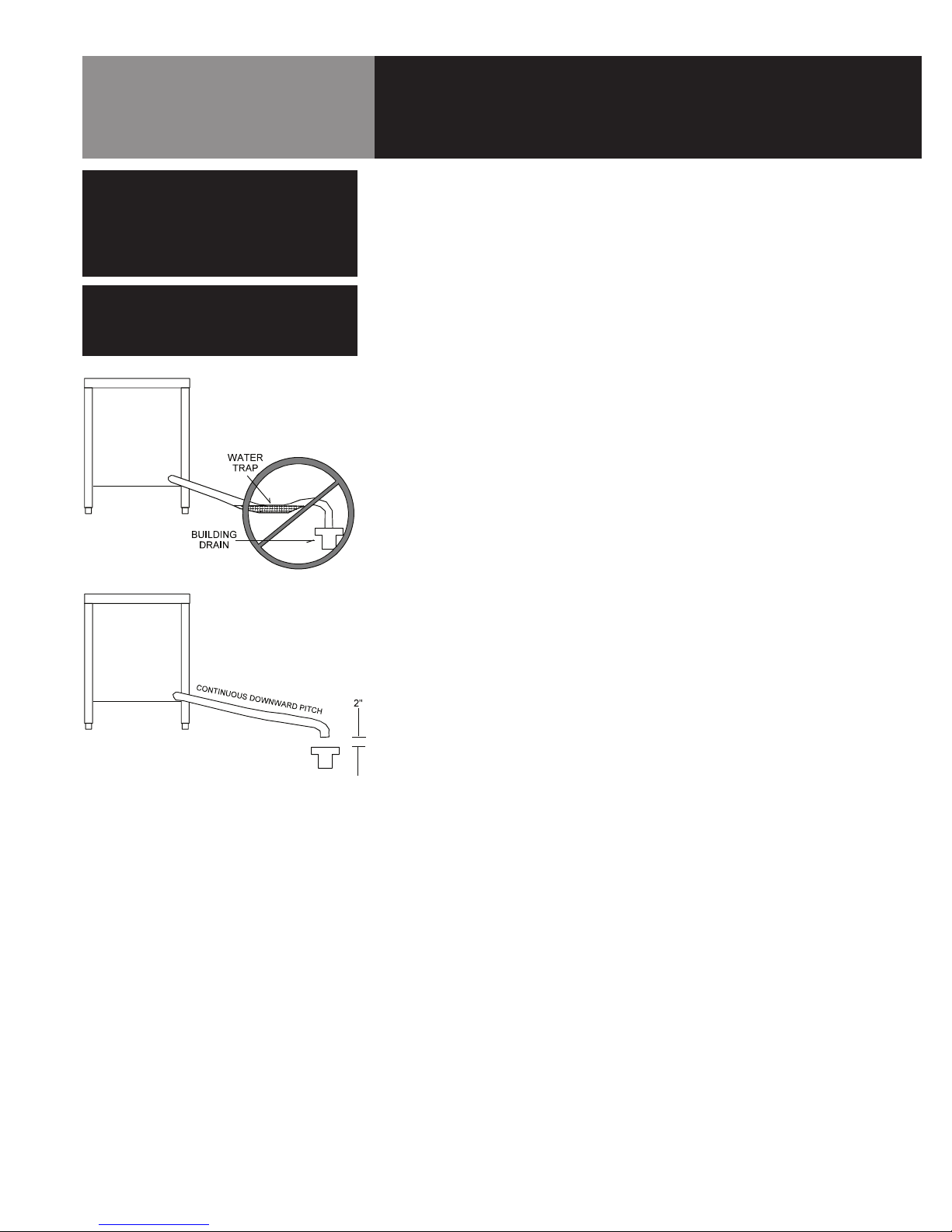
Leave a two-inch air gap between the
hose and the building drain, and don’t
allow water traps in the line.
b. The drain line must be installed with a constant downward pitch. Do
not permit any water traps in the line. DO NOT CONNECT THE LINE
DIRECTLY TO ANY BUILDING DRAIN. A vertical air gap of at least two
inches must be maintained between the drain line and the building drain
unless otherwise specified by local plumbing codes.
OM-NGB/3 7
Page 8
Operating Controls are located on the
front of the cabinet base unit.
Initial Start-Up
After the unit has been installed, test it to ensure that it is operating properly.
1. Remove literature and packing material from the interior and exterior of the unit.
2. Make certain the water supply is turned on.
3. Turn on electrical power to the unit.
4. Make sure the gas supply line is open, and turn on the gas valve.
Turn the knob on the gas valve to the “ON” position.
NOTE: The “trial for ignition” period is approximately 90 seconds after the on/off
switch is turned to the “ON” position. (Refer to the Control Panel illustration in
the Operation Section).
During initial start-up several trials may be necessary to remove air from the gas
piping. Subsequent start-ups should only need about five seconds for the pilot to
light. If the pilot burner does not light within the trial period, the ignition system
will automatically stop gas flow to the pilot burner, and terminate the ignition
trial. If this happens, turn the switch to “OFF” and then “ON” again, to repeat the
trial for ignition.
5. Turn the on/off switch on the cabinet front panel to the “ON” position:
• The amber light in the switch will come on
• The boiler drain valve will close
• The unit will fill with water
When the water level reaches the “mid” probe, the red RESET light will come on.
Push the start switch.
• The green light in the switch will come on
• The RESET light will go out
• The main burner will light
When the water level reaches the “hi” probe, the water supply to the boiler will
shut off.
6. After about 15 minutes, the pressure on the gauge will rise. When the pressure
reaches 9- 1/2 PSI, the main burner will turn off. Thereafter, as pressure
decreases, the burner will automatically re-light to maintain the 9-1/2 PSI level.
The pilot burner should stay lit, even though the main burner cycles on and off.
7. To shut the unit down, turn the on/off switch to OFF. When it has cooled to
approximately 170ºF, the boiler will automatically drain.
The pilot is off when the on/off switch is OFF.
If the boiler functions as described above, it is ready for use. If it does not, contact
your authorized Groen Service Agent.
8 OM-NGB/3
Page 9

Operation
WARNING
ALL POTENTIAL USERS OF THE EQUIPMENT
SHOULD BE TRAINED IN SAFE AND CORRECT
OPERATING PROCEDURES.
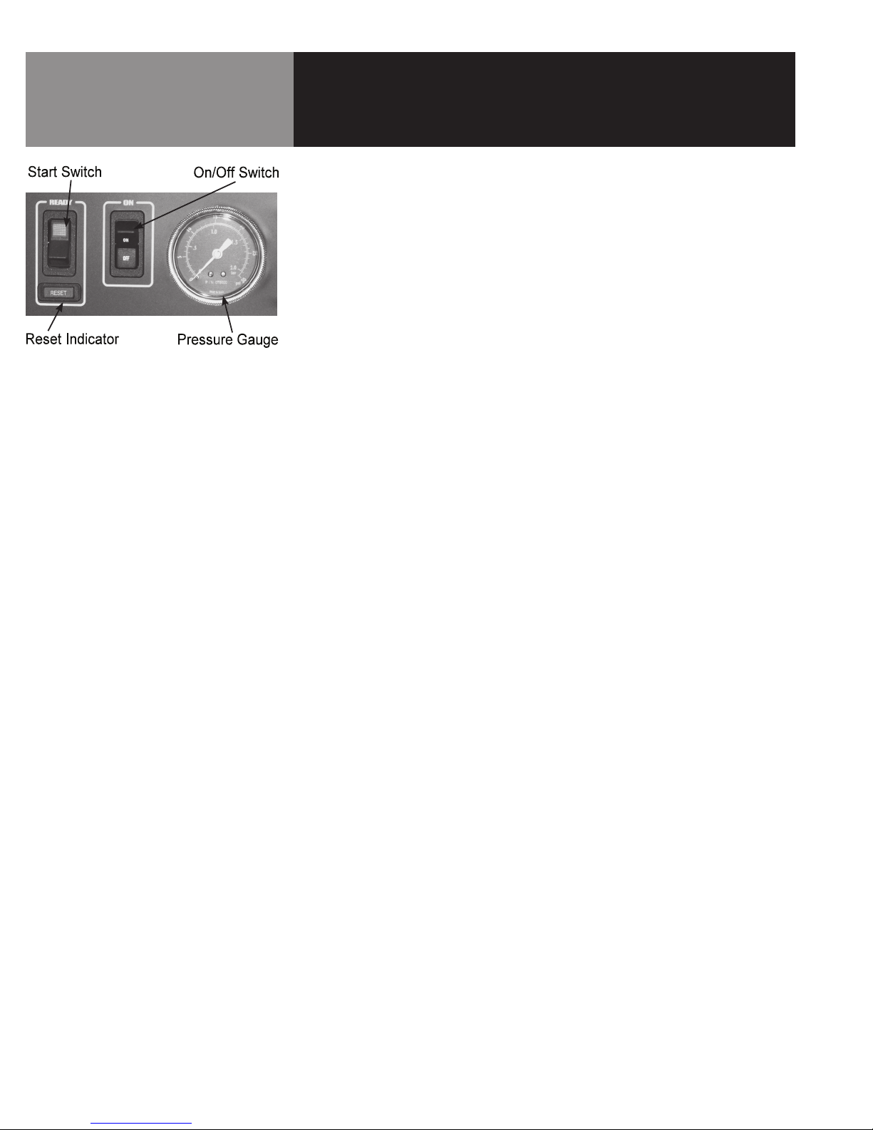
A. Controls
Operating controls are located on the front panel of the unit.
a. The on/off switch starts the unit or shuts it off.
b. The RESET indicator lights to show that the boiler has filled with water
and that the main burners can ignite.
c. The start switch (momentary) lights the main burners. It also restarts
the unit if electrical power is interrupted, or if a low water condition in
the boiler disables the unit.
d. In addition to operating these controls, there are gas supply controls
located on the gas valve.
For NGB/3E: When the control knob is “ON,” gas flows to the pilot, as
well as to the main burners.
B. Operating Procedure
a. Turn on the water supply to the unit.
b. Turn on electrical power to the unit.
c. Turn on the gas supply to the unit, and turn on the gas valve.
Turn the control knob .on the gas valve to the “ON” position.
NOTE: The “ignition trial” period runs for approximately 90 seconds after the on/
off switch is turned ON. This means that if the pilot light does not light within
the “trial” period, the ignition system will automatically stop the gas flow and
terminate the ignition trial. If ignition is terminated, turn the switch off and then
“ON” again to repeat the trial. Normally, the pilot should light within five seconds
of turning on the unit.
d. Turn the on/off switch on the front of the cabinet to “ON.”
1) The amber light will come on.
2) The boiler drain valve will close and the unit will fill with water.
3) When the water reaches the “mid” probe, the red RESET light
will come on.
4) Press the start switch.
5) The green light in the switch will come on, the RESET light will
go off, and the main burner will light.
6) When the water level reaches the “hi” probe, the water supply
to the boiler will shut off.
e. After about 15 minutes, the pressure gauge will indicate that the
pressure is rising. When it reaches 9-1/2 PSI, the main burner will
shut off. Thereafter, the burner will periodically relight to maintain
the pressure at 9-1/2 PSI. The pilot light should stay lit when the
burner is off.
f. To shut down the unit, turn the on/off switch to OFF. The unit will drain
automatically after it has cooled to about 170ºF. The unit turns off the
pilot light when the on/off switch is turned to OFF.
OM-NGB/3 9
Page 10

Sequence of Operation
CAUTION
WAIT AT LEAST 60 SECONDS BEFORE
ATTEMPTING TO RE-LIGHT THE MAIN
BURNER AFTER IT SHUTS OFF.
CAUTION
ESCAPING STEAM MAY CAUSE SEVER
BURNS. STAY AWAY FROM THERMOSTATIC
AIR VENT AND PRESSURE RELIEF VALVES.
When electrical power is turned on to the unit, the following happens:
• The drain valve closes
• The water valve opens
• The unit fills with water
As the boiler fills, the water is detected by two probes. The first of these is the “mid”
probe, which activates the RESET light. The second (“hi” probe) is reached when the
boiler is full, and shuts off the water supply. As the water supply drops below this
probe, the water supply opens until it is again reached.
The gas valve has a step-opening feature. When the control calls for the main burner
to light, the outlet pressure of the valve is maintained at a preset (non-adjustable) rate
for several seconds, before full rated pressure is allowed to develop.
Once the main burner shuts down, step-opening gas valves need at least 60 seconds
to reset. If an attempt to re-light the burner is made before these valves reset, it may
bypass or shorten the length of the low pressure step, and could re-light the main
burner under full flow rate.
A thermostatically-controlled air vent remains open while the boiler fills. As steam
begins to develop, this vent will close. Some steam may escape from this vent before
it is fully closed (at approximately 200ºF).
Once the pressure has reached 9-1/2 PSI, the main burner will be shut off by an
operating pressure switch. Residual heat stored in the boiler’s heat exchanger can,
however, cause the pressure to continue to build, even after the burner has shut down.
This is especially true when the unit is heated for the first time.
If/when the pressure reaches 12 PSI, a relief valve will open to prevent pressure from
increasing past 12 PSI. As pressure decreases, the main burner will automatically relight to maintain 9-1/2 PSI.
Even if something causes the pressure to pass 12PSI, a high-limit safety switch will
shut down the boiler electrically when it reaches 14-1/2 PSI. If this happens, the unit
should not be re-started until the problem which caused the shut-down has been
corrected.
As an additional safety measure, the unit is equipped with an A.S.M.E.-certified safety
valve which will open to relieve excess pressure at 15 PSI. The ability of this valve to
discharge steam pressure is greater than the boiler’s ability to generate steam.
When electrical power is turned off, the gas valve automatically shuts off flow to the
main gas burner.
A thermostatic switch (mounted on the boiler shell) keeps the drain valve closed until
the temperature drops to approximately 170ºF.
At that point, the thermostatic switch opens and water drains from the boiler. A
vacuum breaker allows air to enter the boiler for this purpose.
10 OM-NGB/3
Page 11

Cleaning
WARNING
WATER AND VALVES MAY BE VERY HOT,
AND MAY CAUSE BURNS. PROTECT HANDS
FROM HOT SURFACES AND WATER.
WARNING
USE SAFETY GLASSES AND RUBBER
GLOVES AS RECOMMENDED BY DE-LIMING
AGENT MANUFACTURER.
CAUTION
DO NOT USE A CLEANING OR DE-LIMING
AGENT THAT CONTAINS SULFAMIC ACID
OR ANY CHLORIDES, INCLUDING
HYDROCHLORIC ACID (HCL). IF THE
CHLORIDE CONTENT OF ANY PRODUCT IS
UNCLEAR, CONSULT THE MANUFACTURER.
Whenever the boiler is turned off and allowed to cool to about 170ºF, it drains
automatically. This should be done every day to minimize scale buildup inside the
boiler.
In addition to this draining, however, the following cleaning procedure should be
followed using a regular schedule. This will prevent the accumulation of lime on the
water level probes and interior surfaces of the boiler. The actual time between these
scheduled cleanings depends on the water quality and hours of operation. Minimally,
Groen recommends cleaning the boiler at least once each month.
A. Suggested Tools
a. 1/2” hardened square wrench extension
b. Pipe Joint compound (approved for 300ºF steam)
c. 32 oz. Groen Delimer Descaler (PN 114800), or equivalent
d. Groen Spray Degreaser (PN 114801, or equivalent
e. Nylon pad(s)
B. Procedure
1. Turn the boiler on/off switch to the OFF position.
2. Slowly open the manual drain valve to empty the boiler. The valve is located
under the boiler.
3. Close the manual drain valve.
The manual drain valve is
located under the boiler.
4. Turn off water supply to the boiler.
5. Allow the boiler to cool. This takes several hours, so it is recommended that
you cool the boiler overnight.
6. Turn on/off switch to “ON” to close the automatic drain valve.
7. Using a 1/2” hardened square wrench extension, remove one of the 1” NPT
pipe plugs from the front of the boiler.
8. Pour 32 ounces of de-limer (Groen Delimer Descaler - Part Number
114800), or equivalent) into the boiler.
9. Replace the pipe plug. Use pipe joint compound, and tighten the plug
securely.
10. Turn on water supply to allow water to fill the boiler.
11. When the reset light appears, press the START switch.
12. Allow boiler pressure to develop. Let it stand for approximately 15 minutes
after pressure has built up. A badly limed unit may require more than 15
minutes.
If there are no steamer cavities or compartments with this boiler, proceed
to step 19.
OM-NGB/3 11
Page 12

Cleaning
WARNING
SOLUTION AND VALVES WILL BE VERY HOT,
AND MAY CAUSE BURNS. PROTECT HANDS
FROM HOT SURFACES AND CONTINUE TO
USE PROTECTIVE GLOVES.
13. Set steamer timers for 10 minutes.
14. When steamer timers sound, turn them to OFF and open the doors.
15. When the fans have stopped, remove fan baffle partitions using protective
gloves, and rinse with clean water.
16. Completely wipe out steamer chambers using a degreaser and nylon pad, if
necessary. Rinse thoroughly with clean water.
17. Replace fan baffle partitions.
18. Wait 10 minutes for the compartments to air dry, then close the steamer
doors.
19. Turn the on/off switch OFF, and slowly open the manual drain valve.
20. When the boiler has drained completely, close the manual drain valve and
turn the on/off switch to “ON” to fill the boiler with water.
21. After the RESET light comes on, press the start switch.
22. Allow boiler pressure to develop If steamers are not present, proceed to
step 25.
23. Set steamer timers for 10 minutes.
24. When steamer signal sounds, turn timers off.
25. If the boiler is not to be used, it may be turned off. It is ready for normal
operation.
12 OM-NGB/3
Page 13

Maintenance
WARNING
USE ONLY GROEN-SUPPLIED PARTS.
USING SUBSTITUTE, UNAUTHORIZED OR
“GENERIC” PARTS CAN CAUSE BODILY
INJURY TO THE OPERATOR AND DAMAGE
THE EQUIPMENT.
WARNING
DO NOT EXPOSE SKIN TO ESCAPING STEAM.
SEVERE BURNS MAY RESULT.
Your Groen boiler is designed to minimize maintenance, but certain parts may need
to be replaced after prolonged use. For the most part, no user adjustments should
be necessary. If a need for service arises, only Groen personnel or Authorized Groen
Representatives should perform the work.
Among the most common problems is the rapid build-up of scale in the boiler. To avoid
this, always supply water that has a low mineral content, which meets the standards
described in the Water Quality section of this manual.
A. Periodic Inspection
The unit should be inspected by a qualified service technician at least once each
year. The inspection should include electrical wires and connections, cleaning the
inside of the control enclosure and pilot burner adjustment, if required.
At the back of this manual (with the information about our warranty) is a
Maintenance and Service Log. Each time maintenance is performed on the unit,
enter the date on which it was done, what was done, and who did it. Keep this log
with the warranty.
In addition to yearly inspections by a qualified service technician, a weekly check
of the following will help prevent down time and ensure continued efficient
operation.
1. Pressure gauge operation
2. Proper water level (gauge)
3. Strainer in water feed line (clear?)
4. Air inlets for gas burner jets (clean?)
5. Pilot burner flame (blue? Envelops sensor?)
6. Drain piping (free running? No blockage?)
One of the pressure relief safety valves is
located on the top left rear of the boiler.
At least twice each month, check the safety valve to be sure it is working properly.
When pressure reaches five PSI on the gauge, lift the lever to vent steam, then
release it, allowing it to snap back into place.
B. Component Replacement
NGB/3E boilers are easy to service. The design is simple, and controls are readily
accessible.
Before replacing any part, COMPLETELY SHUT OFF THE GAS AND ELECTRICAL
POWER TO THE UNIT. When breaking (opening) a gas pipe connection, allow five
minutes for gas to dissipate before proceeding.
When the pipes have been reconnected, check for leaks with a thick soap solution
or other suitable leak detector. Do not use flame to check for gas leaks.
OM-NGB/3 13
Page 14

Troubleshooting
Do not operate the unit if it malfunctions or has damaged or broken parts. NGB/3 and NGB/3/E steam boilers are designed to operate
smoothly and efficiently when maintained properly. However, the following is a list of checks to make if there is a problem. Electrical
schematics are provided in this manual, and inside the unit electrical enclosure. IF THE ITEM ON THE LIST IS MARKED WITH (X), THE
WORK SHOULD ONLY BE DONE BY A FACTORY-AUTHORIZED SERVICE REPRESENTATIVE.
SYMPTOM WHO WHAT TO CHECK
Boiler does not ll with water. User a. Is water supply connected and is water present?
b. Is water pressure low (less than 30 PSI)?
c. Is strainer screen (if used) clogged?
d. Is on/off switch in base cabinet turned on? Is the amber light in
the on/off switch “ON”?
e. Is the manual drain valve open?
Authorized
Service Rep Only
Boiler overlls with water. User a. Is the boiler level? Check levelness of unit with a spirit level.
Authorized
Service Rep Only
Boiler under lls with water. User a. Is the boiler level? Check levelness of unit with a spirit level.
Water enters boiler slowly. User a. Is strainer screen (if used) clogged?
Authorized
Service Rep Only
RESET light does not come
on.
Authorized
Service Rep Only
f. Is the Water Level Control Board defective? Check for loose
electrical connections on water ll solenoid. (X)
g. Is the water ll solenoid valve defective? (X)
h. Is the solenoid drain valve open or leaking? Check for loose
electrical connections on solenoid drain valve. (X)
b. Is the water pressure too high? (Greater than 60 PSI?)
c. Is the Water Level Control Board defective? Check for loose
electrical connections on “hi” water ll solenoid. (X)
d. Is the water ll solenoid valve defective? (X) Check for debris on
valve seat.
e. Is the “hi” water probe sensing level? Clean water level probe
and probe well (located in boiler). (X)
b. Is the water pressure too low? (Less than 30 PSI)?
c. Is the water supply line too small?
d. Is the water ll solenoid defective? (X)
a. Is the Is the Water Level Control Board defective? Check for
loose electrical connections on “mid” water ll solenoid. (X)
b. Is the “mid” water probe sensing level? Clean water level probe
and probe well (located in boiler). (X)
c. Is the indicator light defective? (X)
Pilot burner will not light
(spark ignition).
Pilot burner will not stay lit. Authorized
14 OM-NGB/3
User a. Is supply gas valve open?
Authorized
Service Rep Only
Service Rep Only
b. Is gas valve knob in the “ON” position?
c. Is the boiler lled with water? Is the green light in the start switch
“ON”?
d. Does the pilot ame require adjustment? Screw attachment on
gas valve. (X)
e. Is the gas valve defective? (X)
a. Does the pilot ame require adjustment? Screw attachment on
gas valve. (X)
Page 15

Troubleshooting
Main burner will not light
(spark ignition).
Boiler does not build
pressure with main burner lit.
Main burner does not shut off
after reaching operating
pressure.
Boiler builds pressure but
shuts down. RESET light
comes on.
User a. Is pilot burner lit?
b. Is the boiler lled with water? Is the green light in the start switch
“ON”?
Authorized
Service Rep Only
User a. Is the steam power take-off valve open or leaking?
Authorized
Service Rep Only
User a. Is the pressure gauge defective?
Authorized
Service Rep Only
User a. Is the water level below the “mid” water level probe? Verify that
c. Is the igniter-sensor defective? (X)
d. Is the gas valve defective? (X)
e. Is the spark ignition module defective? (X)
b. Is the pressure gauge defective?
c. Is the air vent leaking steam? (X)
d. Is the solenoid or manual drain valve open or leaking? NOTE:
Excessive make-up water added to the boiler reduces steam
production. (X)
e. Is the burner BTU output low? Check the gas pressure at the
burner. Adjust at the gas valve, if necessary. (X)
b. Is the gas valve defective?
c. Is the operating pressure switch defective? No adjustment is
allowed. Replace the switch if defective. (X)
the water supply is sufcient to maintain the water level at or
above the “mid” water level probe.
Authorized
Service Rep Only
Safety relief valve opens. Authorized
Service Rep Only
Boiler blows down
immediately when turned off.
Boiler does not drain. User a. Is the thermostatic switch defective?
Authorized
Service Rep Only
b. Is the operating pressure switch defective? No adjustment is
allowed. Replace the switch if defective. NOTE: If the highlimit pressure switch has shut down the unit, it should not be
restarted until the problem which caused the shut-down has
been corrected. (X)
c. Is the “mid” water level probe unable to detect water? Clean the
water level probe and probe well (located in the boiler). (X)
a. Are the operating pressure switch and/or high-limit pressure
switch defective? No adjustment is allowed. Replace defective
switches. (X)
b. Is the safety relief valve defective? Replace with ASME approved
15 PSI valve with “HV” marking. (X)
a. Is the thermostatic switch defective? Check for loose electrical
connections on switch. (X)
b. Is the solenoid drain valve defective?
c. Are the solenoid drain valve or hoses blocked?
OM-NGB/3 15
Page 16

Parts List
NGB/3 Burner & Gas Valve
Key Description Part #
1 Baffle Plate 083076
2 Pilot Burner Mounting
Bracket
3 Pilot Burner W/ Spark
Igniter-sensor
4 Shield for Pilot Burner 102260
5 Flame Deflector (Single
Loop) Holder for #640
7a Main Burner Assy 0-2000 Ft.
Elev.(Incl. (29) Gas Jets
W/ #54 Drill Dia Hole) For
Natural Gas
7a Main Burner Assy 0-2000 Ft.
Elev.(Incl. (29) Gas Jets
W/ #68 Drill Dia Hole) For
Propane Gas
8 Gas Valve (Spark Ignition)
For Natural Gas
8 Gas Valve (Spark Ignition)
For Propane Gas
9 Spark Ignition Module 085153
10 Ignition Cable 106495
11 Burner Mounting Bracket 050490
12 Kit, Spark Ignition Module
(Included Bracket, Module
and Cable)
102257
102258
056965
047267
050491
101497
104391
137312
12
11
16 OM-NGB/3
Page 17

Key Description Part #
1 Boiler Weldment MS98221
2 Sight Glass Assembly 121754
3 Kit, Repair - Sight Glass 097099
4 Flue Assembly 099217
5 Safety Valve (15PSI) 102297
6 Pressure Relief Valve (12PSI) 099228
Parts List
NGB/3 Boiler
7 Water Level Probes (lo, med,
hi)
8 Solenoid Valve (Water-in) 099220
9 Check Valve 004187
10 Air Vent 145167
11 Vacuum Breaker 090787
12 Globe Valve 1/2”NPT 099255
13 Operating Pressure
Switch-9½ PSI
14 Hi-limit Pressure
Switch-14½ PSI
15 Pressure Gauge 078000
16 Solenoid Valve (Drain) 074594
17 Ball Valve (3/4” NPT) 003436
18 Thermostatic Switch 077985
076526
099222
118255
OM-NGB/3 17
Page 18

Key Description Part #
1 Switch “On/off” 088876
2 Switch “Start” (Momentary) 099290
3 Indicator Light “Reset” 099289
4 Light, Indicator Amber 116384
5 Light, Indicator Red (2) 116383
6 Terminal Block, 2-Pole 003887
Parts List
NGB/3 Electrical Controls
124
- Bushing Snap 11/16” ID 012864
7 Circuit Board Support 099292
8 Water Level Control Board
Assembly
9 Lug, Ground 14-6 AWG 119829
10 Circuit Breaker 119860
11 Transformer, 75VAC 121715
12 Relay, DPDT 24VAC 30A 121733
13 Water Level Control Board
Assembly
- Harness, Electrical Box 130446
14 Bracket, Circuit Breaker 137254
15 Electronic Cabinet,
Weldment
116016
122192
137257
5 3
11 12 6 9 10 15
14
8
18 OM-NGB/3
13 7
Page 19

Electrical Schematic
S1
1
2
3
4
SWITCH CONTACT ARRANGEMENT
VIEWED FROM REAR
ON SWITCH
12
4 3
S1
1
2
R
LOW WATER
12
Y
FILL
1
2
R
HI PRESSURE
RESET SWITCH
S2-1S2-2
B
A
R
RESET
S2-A
S2-B
G
READY LIGHT
S2
2
1
A
P2
J2
4 RED
2B LUE
12 BLUE
9 BLACK
5 BLACK
10 RED
6
7
8 WHITE
GRN
RED1
ORANGE3
ORANGE
BROWN
4
3
B
TO T3
@
STEAMER
WHITE
BLACK
78
K1
SINGLE WATER LEVEL CONTROL
01
K1
TO 120V AC
HN GND
1
CB1
10A
2
120V
3A
24VAC
HI
75VA
T1
DUAL WATER LEVEL CONTROL
3
2
C1
C2
BROWN
C
K1
NC1
NO2
NO
H
LLCO
G
PC2
LLCO
G
4
WHITE
WHITE
N01
NC2
NC
L1
L2
L1
L2
FROM T2
@ STEAMER
TO K7 COIL
@ STEAMER
COM
BLACK
WHITE
21
SPRAY VALVE
LO
BROWN
PC1
P1 J1
11WHITE
1RED
2BLUE
3BROWN
5BLUE
6BROWN
8BLACK
7YELLOW
4BLACK
9RED
10BLACK
12BLACK
1
TSTAT
CLOSES @ 170°
14.5 PSI
HI LIMIT
C
HL
1 2
2
DRAIN VALVE
12
FILL VALVE
HI
PROBE
MID
PROBE
NO
NC
LO
PROBE
OPERATING PRESSURE
SW
9.5 PSI
C
PS
NC
TO SPARK
SPARK
SPARK IGNITION MODULE
24V
GND
PV
GND BURN
MV/PV
BLACK
YELLOW
BLUE
WHITE
G
MAIN
PILOT
H
C
G
MV
OM-NGB/3 19
GAS VALVE
Page 20

Service Log
Model No: Purchased From:
Serial No: Location:
Date Purchased: Date Installed:
Purchase Order No: For Service Call:
Date Maintenance Performed Performed By
20 OM-NGB/3
Page 21

Service Log
Model No: Purchased From:
Serial No: Location:
Date Purchased: Date Installed:
Purchase Order No: For Service Call:
Date Maintenance Performed Performed By
OM-NGB/3 21
Page 22

Service Log
Model No: Purchased From:
Serial No: Location:
Date Purchased: Date Installed:
Purchase Order No: For Service Call:
Date Maintenance Performed Performed By
22 OM-NGB/3
Page 23

Service Log
Model No: Purchased From:
Serial No: Location:
Date Purchased: Date Installed:
Purchase Order No: For Service Call:
Date Maintenance Performed Performed By
OM-NGB/3 23
Page 24

1055 Mendell Davis Drive • Jackson MS 39272
888-994-7636 • 601-372-3903 • Fax 888-864-7636
unifiedbrands.net
© 2014 Unified Brands. All Rights Reserved. Unified Brands is a wholly-owned subsidiary of Dover Corporation.
PART NUMBER 121003 REV D (07/14)
 Loading...