

Page 1
? IMPORTANT INFORMATION ? KEEP FOR OPERATOR ? IMPORTANT INFORMATION ?
OPERATOR MANUAL OM-NGB/3(S)
CSD-1 FIELD INSTALLATION SUPPLEMENT
Part Number 123490 DOMESTIC
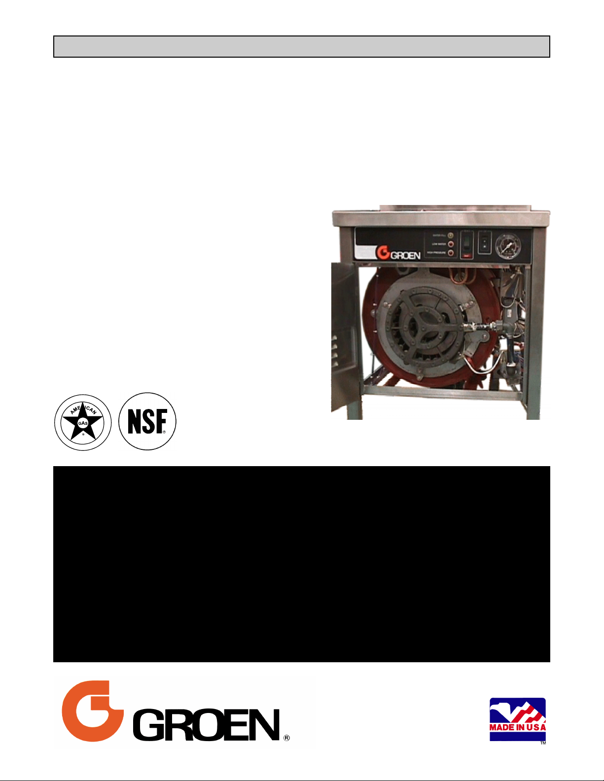
Model: NGB/3, NGB/3/E
Steam Boilers — CSD-1 Kit
Gas Heated
200,000 BTU/hr firing rate
120,000 BTU into product
3.7 effective boiler horsepower
FOR YOUR SAFETY
DO NOT STORE OR USE GASOLINE OR OTHER FLAMMABLE VAPORS AND LIQUIDS IN THE VICINITY OF
THIS OR ANY OTHER APPLIANCE.
READ THE BASIC OPERATOR MANUAL, AND INSTALLATION, OPERATING AND MAINTENANCE
INSTRUCTIONS THOROUGHLY BEFORE INSTALLING, OPERATING OR SERVICING THIS EQUIPMENT.
POST IN A PROMINENT LOCATION
INSTRUCTIONS TO BE FOLLOWED IN THE EVENT USER SMELLS GAS. THIS INFORMATION SHALL
BE OBTAINED BY CONSULTING YOUR LOCAL GAS SUPPLIER. AS A MINIMUM, IMMEDIATELY TURN
OFF THE GAS AND CALL YOUR GAS COMPANY AND YOUR AUTHORIZED SERVICE AGENT.
EVACUATE ALL PERSONNEL FROM THE AREA.
WARNING
IMPROPER INSTALLATION, ADJUSTMENT, ALTERATION, SERVICE OR MAINTENANCE CAN CAUSE
PROPERTY DAMAGE, INJURY OR DEATH.
Information contained in this document is
known to be current and accurate at the time
of printing/creation. Unified Brands recommends referencing our product line websites,
unifiedbrands.net, for the most updated
product information and specifications.
Page 2

OM-NGB/3(S)
IMPORTANT — READ FIRST — IMPORTANT
WARNING: THE UNIT MUST BE INSTALLED BY PERSONNEL QUALIFIED TO WORK WITH GAS,
ELECTRICITY AND PLUMBING. IMPROPER INSTALLATION CAN CAUSE INJURY TO
PERSONNEL AND/OR DAMAGE TO THE EQUIPMENT. THE UNIT MUST BE INSTALLED IN
ACCORDANCE WITH APPLICABLE CODES.
CAUTION: AN ELECTRICAL GROUND IS REQUIRED.
CAUTION: DO NOT LOCATE THE BOILER CABINET DIRECTLY OVER A FLOOR DRAIN OR FLOOR
SINK. HUMIDITY OR WATER FROM A DRAIN WILL DAMAGE ELECTRICAL PARTS OF A
UNIT.
WARNING: TO AVOID DAMAGE OR INJURY, FOLLOW THE WIRING DIAGRAM EXACTLY WHEN
CONNECTING A UNIT.
CAUTION: DO NOT USE PLASTIC PIPE. DRAIN MUST BE RATED FOR STEAM AND BOILING WATER.
WARNING: DO NOT CONNECT THE DRAIN DIRECTLY TO A BUILDING DRAIN.
WARNING: BLOCKING THE DRAIN MAY BE HAZARDOUS.
IMPORTANT: Improper drain connection will void warranty.
WARNING: ALLOW COOKING CHAMBERS TO COOL BEFORE CLEANING.
WARNING: CAREFULLY READ THE WARNINGS AND FOLLOW THE DIRECTIONS ON THE LABEL OF
EACH CLEANING AGENT. USE SAFETY GLASSES AND RUBBER GLOVES AS
RECOMMENDED BY DELIMING AGENT MANUFACTURER.
WARNING: DO NOT MIX DE-LIMING AGENTS (ACID) AND DE-GREASERS (ALKALI) IN THE STEAM
GENERATOR OR ON THE COOKING CHAMBER WALLS.
NOTICE: Do not use a cleaning or de-liming agent that contains any sulfamic acid or any chloride,
including hydrochloric acid (HCl). If the chloride content of any product is unclear, consult
the manufacturer.
NOTICE: Do not use a de-greaser that contains potassium hydroxide or sodium hydroxide or that is
highly alkaline.
WARNING: USE OF ANY REPLACEMENT PARTS OTHER THAN THOSE SUPPLIED BY GROEN OR
THEIR AUTHORIZED DISTRIBUTOR VOIDS ALL WARRANTIES AND CAN CAUSE BODILY
INJURY TO THE OPERATOR AND DAMAGE THE EQUIPMENT. SERVICE PERFORMED BY
OTHER THAN FACTORY-AUTHORIZED PERSONNEL WILL VOID ALL WARRANTIES.
WARNING: HIGH VOLTAGE EXISTS INSIDE CONTROL COMPARTMENTS. DISCONNECT FROM
BRANCH BEFORE SERVICING. FAILURE TO DO SO CAN RESULT IN SERIOUS INJURY OR
DEATH.
WARNING: DO NOT EXPOSE SKIN TO ESCAPING STEAM. SEVERE BURNS CAN RESULT.
2
Page 3

OM-NGB/3(S)
Introduction
This document supplements the basic OM-NGB/3 Operator Manual by providing instructions for modifying boilers
with a new A.S.M.E. CSD-1 code-compliant control system. Performing this modification alters the boiler system
as described in OM-NGB/3-E Supplement New Boiler Control System (Part Number 133530), which is
incorporated into this supplement as Section II, Operation. Other than the instructions in that supplement/ section,
the provisions of OM-NGB/3 apply.
Section I - Installation Instructions
WARNING
THIS MODIFICATION MUST BE MADE BY PERSONNEL WHO ARE WELL-QUALIFIED TO WORK WITH
ELECTRICITY. IMPROPER MODIFICATIONS CAN CAUSE INJURY TO PERSONNEL AND/OR DAMAGE TO
EQUIPMENT. THE UNIT MUST BE INSTALLED IN COMPLIANCE WITH APPLICABLE CODES.
THE BOILER MUST BE THOROUGHLY TESTED FOLLOWING MODIFICATION, AS DIRECTED IN THIS
SUPPLEMENT, TO ENSURE THAT CONNECTIONS WERE PROPERLY MADE AND TO PREVENT
HAZARDOUS CONDITIONS.
A. REMOVAL (Refer to the schematic appropriate
to the unit).
1. Turn off unit and completely disconnect power at
its source.
2. Shut off the gas supply in the line leading to the
unit or at the main valve.
3. If the unit has water in the boiler at the time of
shut-down, it will drain.
WARNING
THE OUTSIDE OF THE BOILER MAY BE VERY
HOT AND CAN CAUSE BURNS. COOL OR
ALLOW THE BOILER TO COOL COMPLETELY
BEFORE PROCEEDING.
(Note: Draining by cutting off power can be used to
cool the boiler more rapidly: Once it has drained,
reconnect the power and allow the unit to fill with
cold water. Repeat this process until the unit is
cool.) Be sure to turn the unit off and disconnect
from power before any wiring is disturbed.
4. Remove the side panels.
5. Cut wire ties which are holding wiring harnesses
located at the left side of the control box, along
the top left of the front control panel and along
the left side of the unit frame tubing. Use pliers
to cut the wire ties.
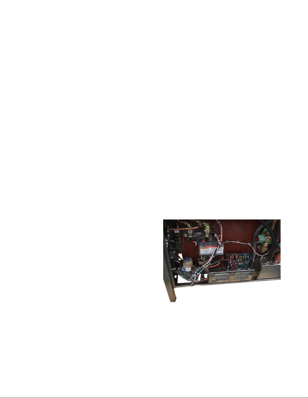
6. Disconnect the wiring from the boiler shell,
probes, front panel, and drain valve, noting
Remove the wire ties to disconnect wiring.
location and markings of the wires.
Disconnect the wiring from the gas valve and the
spark ignition module, but DO NOT disconnect
the wiring which runs directly from the module to
the gas valve. (These wires are a separate
three-wire harness which will be reused in the
new installation). DO NOT disconnect the large
orange spark ignition lead wire.
7. Remove the four screws that attach the spark
ignition module to its bracket. This will allow
access to the pressure switch enclosure located
directly above the module.
3
Page 4
OM-NGB/3(S)
8. Remove the cover from the pressure switch
enclosure.
9. Loosen the screws and remove the wires from
the pressure switches. Note that the high limit
switch is toward the rear of the unit and that its
wiring is marked PSH. The operating pressure
switch is toward the front of the unit. Its wiring is
marked PSL. Remove the wires from the
pressure switch enclosure.
10. Remove high limit pressure switch P/N 099223
and replace with P/N 118255 supplied with kit.
11. Remove the cover from the main electrical
control box.
NOTE: If the unit does not have HyPLUS steamer
cavities installed, skip steps 12, 13 and 14)
12. Disconnect the three wiring plug terminals that
come from the steamer cavities, noting the
markings on each. These are located in the
conduit that comes from the steamer cavities at
the right side of the control box facing the right
side of the boiler cabinet.
13. Loosen the screws on the transformer labeled
H1 and H2 and remove the two fork terminals
that lead to the steamer cavities. (Note: see
Installation Step 3, below, if terminal H2 is not
used in unit installation).
14. Remove the conduit connector nut and the
conduit connector and its wiring from the control
box.
2. Mount the transformer into the new control box
using the four mounting screws.
3. Connect wiring to the transformer at terminals
XF, X2, H1, and H2. Note that the X2 terminal
has a wire labeled X2 and a green ground wire.
Also note that the H3 or H4 terminals may be
used in your installation if unit supply voltage is
other than 120 Volts. The H2 terminal is for 120
Volt installations.
4. Place the control box in the cabinet and mount it
with four screws.
5. Install the conduit connector at the right of the
control box and attach the wiring plug and fork
terminals that were removed in steps 11, 12, and
13. Connections are the same as for the
previous installation.
6. Connect wiring to the fill valve, spray valve,
thermostat switch, spark ignition module, and
gas valve.
7. Insert the six wires with fork terminals into the
pressure switch enclosure. Using the pressure
switch that was removed for reference, attach
the three terminals marked PSH to the high limit
pressure switch. Attach the two terminals
marked PSL to the operating pressure switch.
8. Loosen the screw that attaches the pressure
switch enclosure to the bracket at the left side of
15. Remove the four mounting screws at the bottom
of control box which attach the box to the cabinet
frame.
16. Remove the control box and any wires which
may still be connected.
17. Loosen the screws labeled X1 and XF on the
transformer and remove the transformer wiring.
Remove the four mounting screws which hold
the transformer and disconnect the transformer
from the old control box.
18. Remove power cord and its connector from the
old control box.
B. INSTALLATION(Refer to the appropriate
schematic at the back of this supplement).
1. Install power cord and connector in new control
box.
All wiring must be reconnected when the new
control box is installed.
box. Do not remove! Place the remaining
terminal marked BLR – GND behind this screw
and tighten the screw.
9. Mount the spark ignition module using four
screws.
4
Page 5

10. Place the water level probe covers over the
terminals on the wires marked LO, MID, and HI.
Place the terminals on their respective water
level probes. Since these will be removed during
testing, only hand-tighten the nuts at this time.
11. Position the indicator light overlay to the left of
the start switch approximately one inch away.
Use tape to hold overlay in position. Mark the
position of three indicator light holes with a
center punch. Remove the overlay.
12. Drill three c” pilot holes in the front panel at
marked position. Further drill these holes out
using a ¼" drill then a d” bit.
OM-NGB/3(S)
Carefully connect Control Panel wiring.
provided at the left side of the control box.
Install the cover on the control box, making sure
that wiring is not pinched by the cover.
C. TESTING
The Indicator Light Overlay is positioned to the
left of the Start Switch.
13. Apply the overlay over the holes.
14. Connect front panel wiring to the front panel
components as follows: WF – water fill
indicator, LW – low water indicator, HP – high
pressure indicator, RES – reset indicator, S1 –
on / off switch, S2 – start switch. See diagram
shown below for further switch terminal
identification.
15. Route the drain valve wires along the front panel,
down the left front corner, and along the frame.
Connect the wires to the drain valve.
16. Using wire ties, attach the front panel wires and
drain valve wires to the clips provided. Be sure
no wiring is near the gas burner or the boiler
shell. Only water level probe wiring may touch
the boiler shell.
17. Complete the installation by loosely bundling the
wiring harness and attaching it to the anchor
1. Connect unit to power supply. Leave gas
supply turned off.
2. Turn unit on. Water Fill and Low Water indicator
lights should come on. Wait until both indicators
go out and the Reset light comes on.
3. Press START. The Reset light should go out
and green light inside the start switch should
come on to indicate normal operation. This
should be followed by trial for ignition during
which you should be able to see and hear the
electronic spark near the main burner at the pilot
burner. The trial for ignition will continue for
approximately 90 seconds. If this is the case
proceed with the test.
4. First turn the unit off, then turn on the gas
supply.
5. Repeat steps 2 and 3. When the Start switch is
depressed, trial for ignition should be followed by
pilot burner ignition, which in turn should be
followed by main burner ignition. If this is the
case proceed with the test.
6. Turn unit off, and then on again. Wait until the
Low Water and Water Fill indicator lights go out
and the Reset light comes on.
7. Remove the water probe wire marked LOW from
the water probe. Wait 3 to 6 seconds. The Low
Water indicator light should come on. Touching
the terminal to the probe should make the Low
5
Page 6

OM-NGB/3(S)
Water indicator go out and the Reset light come
on. Reconnect the terminal to the probe.
8. Repeat step 7 for the wire marked MID. The
same results should occur.
9. Turn off the power switch. If steps 7 and 8 were
successful, tighten the nuts on all three water
level probes. Bend terminals up and slip the
water level probe covers over the probes.
15. Install the cover on the pressure switch
enclosure.
16. Reinstall the cabinet covers and doors which
were removed for installation.
Water Level Probes are located on top of the
boiler, above the control box.
10. Turn unit on and wait until the Reset indicator is
lit. Press the Start switch to fire the boiler.
When main burner is lit, proceed with testing.
11. Use a small blade screwdriver to trip the high
limit pressure switch. This is the pressure switch
located toward the rear of the unit which was
changed during the installation. When the
switch is tripped, the main burner should shut
down and the High-pressure indicator light
should come on. When screwdriver is removed,
the High-pressure light should go out and the
Reset light should come on.
12. If safety checks were normal proceed with the
operational test. If not, retrace wiring
connections and correct any mistakes made.
13. Press Start switch to fire the boiler. Allow boiler
to build pressure. The main burner should shut
down at approximately 9.5 PSI.
14. Turn on both steamer cavities and verify that the
main burner cycles to maintain between five and
10 PSI. If burner fires continuously, turn off one
steamer cavity until the burner cycles. Cycling
indicates a successful operational test.
Switch Wiring Terminal Connections (Rear View)
6
Page 7

Section 2 - Operation
The new system is marked by the addition of
three indicator lights on the front panel.
Water Fill
Low Water
High Pressure
Other controls are unchanged.
When the unit is turned on, the unit will begin to
fill with water. Until it is filled, the Water Fill and
Low Water indicator lights will be on.
Once the unit is filled, and ready to operate,
those lights will go out and the Reset light will
come on. The unit is now ready for operation.
Press the start switch to light the boiler. The
Reset light will go out and the green light will
come on showing normal operation.
OM-NGB/3(S)
During operations the Low Water indicator will
only light when the water level drops below its required level. When this occurs, the boiler will immediately cease
firing and the green light will go out. Until the water has again reached the proper level, the reset light will not
come on, and the unit will not operate.
The same is true when a high pressure situation occurs. The High Pressure indicator light will come on, the boiler
will stop firing, and the green light will turn off. If this situation occurs, contact an authorized Groen service
agency. Until the high pressure situation has been resolved, the reset light will not come on and the unit will not
operate.
7
Page 8

OM-NGB/3(S)
Wiring Schematic - Electronic Ignition
8
Page 9

OM-NGB/3(S)
Wiring Schematic - Standing Pilot
9
Page 10

OM-NGB/3(S)
Parts List
Key Description Part No. Key Description Part No.
1 Assembly, Electrical Control, NGB/3 123489 5 Light. Indicator, Red 122121
2 Water Level Control 24 VAC 122192 6 Overlay, Front Panel HY6 SE & HY 6SG 122188
3 Switch, Pressure, High Limit 118255 7 Schematic, Wiring - Electric Ignition 122193
4 Light, Indicator, Yellow 122122 8 Schematic, Wiring - Standing Pilot 123416
10
Page 11

OM-NGB/3(S)
LIMITED WARRANTY TO
COMMERCIAL PURCHASERS*
(Continental U.S., Hawaii and Canadian Sales Only)
Groen Foodservice Equipment (“Groen Equipment”) has been skillfully manufactured, carefully inspected,
and packaged to meet rigid standards of excellence. Groen warrants its Equipment to be free from defects in
material and workmanship for (12) twelve months, with the following conditions and subject to the following
limitations.
This parts and labor warranty is limited to Groen Equipment sold to the original commercial
purchaser/users (but not original equipment manufacturers {O.E.M.}), at its original place of installation in
the continental United States, Hawaii and Canada.
Damage during shipment is to be reported to the carrier, is not covered under this warranty, and is the
sole responsibility of the purchaser/user.
Groen, or an authorized service representative, will repair or replace, at Groen’s sole election, any Groen
equipment, including but not limited to, drawoff valves, safety valves, gas and electric components, found
to be defective during the warranty period. As to warranty service in the territory described above, Groen
will absorb labor and portal to portal transportation costs (time and mileage) for the first twelve (12)
months from date of installation or fifteen (15) months from date of shipment from Groen.
This warranty does not cover boiler maintenance, calibration, periodic adjustments as specified in
operating instructions or manuals, and consumable parts such as scraper blades, gaskets, packings,
etc., or labor costs incurred for removal of adjacent equipment or objects to gain access to Groen
Equipment. This warranty does not cover defects caused by improper installation, abuse, careless
operation, or improper maintenance of equipment. This warranty does not cover damage caused by
poor water quality or improper boiler maintenance.
THIS WARRANTY IS EXCLUSIVE AND IS IN LIEU OF ALL OTHER WARRANTIES, EXPRESS OR
IMPLIED, INCLUDING ANY IMPLIED WARRANTY OF MERCHANTABILITY OR FITNESS FOR A
PARTICULAR PURPOSE, EACH OF WHICH IS HEREBY EXPRESSLY DISCLAIMED. THE
REMEDIES DESCRIBED ABOVE ARE EXCLUSIVE AND IN NO EVENT SHALL GROEN BE LIABLE
FOR SPECIAL, CONSEQUENTIAL OR INCIDENTAL DAMAGES FOR THE BREACH OR DELAY IN
PERFORMANCE OF THIS WARRANTY.
Groen Equipment is for commercial use only. If sold as a component of another (O.E.M.) Manufacturer’s
equipment, or if used as a consumer product, such Equipment is sold AS IS and without any warranty.
*(Covers all Foodservice Equipment Ordered after October 1, 1995)
11
Page 12

1055 Mendell Davis Drive
Jackson, MS 39272
Telephone: 601 372-3903
Fax: 601 373-9587
OM-NGB/3(S)
Part Number 123490
 Loading...