

Page 1
THIS MANUAL MUST BE RETAINED FOR FUTURE REFERENCE
FOR YOUR SAFETY
DO NOT STORE OR USE GASOLINE OR OTHER FLAMMABLE VAPORS AND
LIQUIDS IN THE VICINITY OF THIS OR ANY OTHER APPLIANCE
POST IN A PROMINENT LOCATION
INSTRUCTIONS TO BE FOLLOWED IN THE EVENT USER SMELLS GAS.
THIS INFORMATION SHALL BE OBTAINED BY CONSULTING YOUR LOCAL
GAS SUPPLIER. AS A MINIMUM, TURN OFF THE GAS AND CALL YOUR
LOCAL GAS COMPANY AND YOUR AUTHORIZED SERVICE AGENT.
EVACUATE ALL PERSONNEL FROM THE AREA.
WARNING: IMPROPER INSTALLATION, ADJUSTMENT. ALTERATION,
SERVICE OR MAINTENANCE CAN CAUSE PROPERTY DAMAGE, INJURY
OR DEATH. READ THE INSTALLATION, OPERATING AND MAINTENANCE
INSTRUCTIONS THOROUGHLY BEFORE INSTALLING OR SERVICING THIS
EQUIPMENT.
Page 2
IMPORTANT — READ FIRST — IMPORTANT
Congratulations on your purchase of the highly efficient Groen gas heated steam generator: This unit has been
carefully designed and handcrafted in, our own machine shop, then meticulously inspected
and pretested to ensure that you receive the best possible product. Given reasonable care and periodic
maintenance, this generator will provide years of faithful service.
PLEASE READ THIS MANUAL CAREFULLY AND THOROUGHLY BEFORE INSTALLING OR OPERATING THE
GENERATOR. Keep. it on hand for future reference.
It is recommended that you establish a timetable for periodic maintenance as outlined in this manual. Space has
been provided in the Maintenance and Service Log. Keep it up to date and on file with the warranty information
contained in this manual.
A warranty registration card will be attached to the unit. Fill in this card and mail it to Groen Record the model
number, serial number and installation date of your unit at the top of the Maintenance and Service Log in the
back of this manual. File this information for future reference.
CONDITIONS AND TERMS OF LIMITED THREE YEAR WARRANTY
The warranty on this unit does not extend to:
1. Installation and start up.
2. Simple adjustments, such as tightening fittings and electrical connections.
3. Malfunction as a result of improper maintenance.
4. Repairs made by anyone other than qualified service personnel as recommended by Groen.
5. Damage caused in shipment or damage as a result of improper use.
6. Normal maintenance as outlined in operator manual.
7. Damage as a result of excessive moisture in components. DO NOT SPRAY EQUIPMENT WITH WATER
OR STEAM.
8. Damage caused by tampering with, removal of. or change of preset controls or safety device.
9. Malfunction as a result of sediment and/or lime in the valves or scale build-up in the boiler.
NOTE: MINIMUM WATER QUALITY STANDARDS MUST BE MET TO INSURE PROPER OPERATION. WATER
SOFTENING IS RECOMMENDED IF YOUR WATER QUALITY DOES NOT MEET THE FOLLOWING
STANDARDS:
(1) Total dissolved solids (TDS) content should not exceed 30 parts per million.
(2) Water pH should be 7.0 or higher.
CAUTION: USE OF ANY REPLACEMENT PARTS OTHER THAN THOSE SUPPLIED BY GROEN OR THEIR
If you have any questions about warranty coverage, operating procedures, or maintenance, contact your area Groen
representative or an authorized Groen service agency.
AUTHORIZED DISTRIBUTOR VOIDS ALL WARRANTIES. SERVICE PERFORMED BY OTHER THAN
FACTORY AUTHORIZED PERSONNEL WILL VOID ALL WARRANTIES.
Page 3
Table of Contents
EQUIPMENT DESCRIPTION .............................................................................................2
INSTALLATION .......................................................................................................... 2,3, 4
INITIAL START-UP ........................................................................................................4, 5
OPERATION ..................................................................................................................5,6
SEQUENCE OF OPERATION ............................................................................................7
WATER CONDITIONING ...................................................................................................8
REFERENCES ..................................................................................................................8
MAINTENANCE & CLEANING ..................................................................................... 9, 10
TROUBLESHOOTING ....................................................................................11, 12, 13, 14
PARTS LISTS ............................................................................................5, 16, 17, 18, 19
DIAGRAMS & SCHEMATICS...........................................................................20, 21, 22, 23
MAINTENANCE LOG ......................................................................................................24
WARRANTY INFORMATION ...........................................................................................25
1
Page 4
Equipment Description
The Groen NGB and NGB/E steam generators are designed to generate Low pressure steam tor use in GOLDLINE
cabinet mounted steamers and steam jacketed kettles.
The generator is housed in a stainless steel cabinet on top of which can be mounted various combinations of
steamers and kettles requiring a steam supply. It is small enough to fit in a 24 inch wide cabinet.
The NGB and NGB/E feature an easily accessible control box, which may be pulled out through the cabinet door for
servicing. (See Troubleshooting section of this manual.)
The generator itself is constructed or 1/4 inch-boiler plate according to ASME code (all welds are hydrostatically
tested) and is equipped with all required instruments, fittings, and controls.
Heat transfer fins inside the combustion chamber add to the high efficiency of this unit. The NGB and NGB/E are
both rated as 60% efficient or better, with a firing rate of 200,000 BTU/hr using propane or natural gas. The energy
output is 120,000 BTU/hr and effective boiler horsepower is 3.6.
The two models are distinguished by different ignition systems. to ignite the burners. Model NGB utilizes a standing
pilot but Model NGB/E employs a Corborundum glow coil.
Installation
WARNING: INSTALLATION OF THE STEAM GENERATOR MUST BE DONE BY PERSONNEL QUALIFIED TO WORK
WITH ELECTRICITY AND PLUMBING. IMPROPER INSTALLATION CAN CAUSE INJURY TO PERSONNEL
AND/OR DAMAGE TO THE EQUIPMENT. ANY MECHANICAL, ELECTRICAL, OR GAS TYPE CHANGE
MUST BE APPROVED BY THE GROEN DIVISION FOOD SERVICE ENGINEERING DEPARTMENT.
The unit should be installed in a ventilated room for efficient performance. All items which may obstruct or restrict
the flow of air for combustion and ventilation must be removed. The area directly around the appliance must be
cleared of all combustible materials.
1. Installation on both combustible and noncombustible floors is allowed, with a minimum clearance to
combustible construction of six (6) inches at the rear and six (6) inches at each side.
2. Installation of the Gas Steam Generator under a ventilating hood is required. Installation of the ventilating
hood should comply with local codes and/or ANSl/NFPA-96 Latest Edition. Also, the Gas Steam Generator
should be electrically interlocked to shut off the gas supply and prevent the operation or the unit if the exhaust
fan is not operating or if the fire suppression system is activated. Failure to follow these instructions can
cause bodily injury and/or property damage.
3. Level the unit by adjusting the legs. and check for levelness with a spirit level on top of the cabinet.
4. Complete the piping to the gas service main using 1/2 inch NPT pipe or approved equivalent. Connection to
the gas valve is at the right front corner of the generator.
5. Provide 115 VAC, 60 HZ, 1 PH, 15 AMP electrical service. Observe local codes and/or The National
Electrical Code in accordance with ANSI/NFPA 70 — latest edition. AN ELECTRICAL GROUND IS
REQUIRED. The electrical schematic is located on the inside of the cabinet door.
6. Installation must conform with the American National Standard Z223.1 — latest edition and the National Fuel
Gas Code. The unit should be installed in an adequately ventilated room with a provision for adequate air
supply to the unit. The best ventilation will utilize a vent hood and exhaust fan. DO NOT obstruct the flue or
vent duct after installation.
7. Adequate space for proper servicing and operation is required. DO NOT block any air intake spacing to the
combustion chamber or obstruct the air flow.
8. After the steam generator has been connected to the gas supply, all gas line joints must be checked for
leaks. NO FLAME SHOULD BE USED WHEN CHECKING FOR LEAKS. A thick soap solution or other
suitable leak detector should be employed.
9. The appliance and its individual shutoff valve must be disconnected from the gas supply piping system
during any pressure testing of the system at test pressures in excess of 1/2 psig (3.48 kPa). The appliance
must be isolated from the gas supply piping system by closing its individual manual shutoff valve during any
pressure testing of the gas supply piping system at test pressures equal to or less than 1/2 psig (3.48 kPa).
2
Page 5
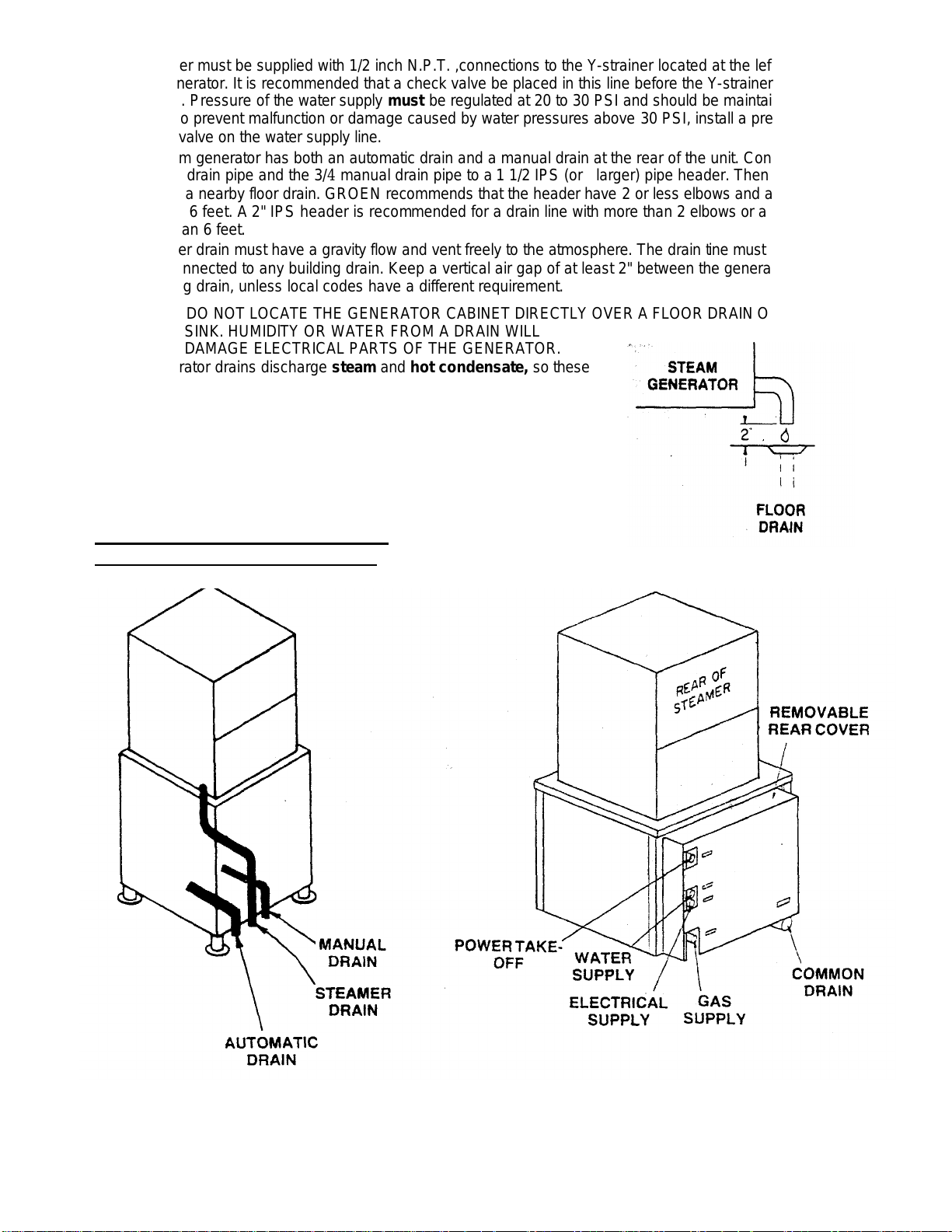
10. Cold water must be supplied with 1/2 inch N.P.T. ,connections to the Y-strainer located at the left rear corner
of the generator. It is recommended that a check valve be placed in this line before the Y-strainer to prevent
back flow. Pressure of the water supply must be regulated at 20 to 30 PSI and should be maintained at 25 to
30 PSI. To prevent malfunction or damage caused by water pressures above 30 PSI, install a pressure
reducing valve on the water supply line.
11. This steam generator has both an automatic drain and a manual drain at the rear of the unit. Connect the 1/2
automatic drain pipe and the 3/4 manual drain pipe to a 1 1/2 IPS (or larger) pipe header. Then extend the
header to a nearby floor drain. GROEN recommends that the header have 2 or less elbows and a length of no
more than 6 feet. A 2" IPS header is recommended for a drain line with more than 2 elbows or a length
greater than 6 feet.
The header drain must have a gravity flow and vent freely to the atmosphere. The drain tine must not be
directly connected to any building drain. Keep a vertical air gap of at least 2" between the generator drain and
the building drain, unless local codes have a different requirement.
CAUTION: DO NOT LOCATE THE GENERATOR CABINET DIRECTLY OVER A FLOOR DRAIN OR FLOOR
SINK. HUMIDlTY OR WATER FROM A DRAIN WILL
DAMAGE ELECTRICAL PARTS OF THE GENERATOR.
The generator drains discharge steam and hot condensate, so these
hot discharges must be directed away from the generator cabinet.
GROEN recommends that the floor drain be located to the rear of the
cabinet. .
For instructions on installation of the steam drain, see the separate
steamer manual.
For units made before August 8,1991:
For units made after August 7,1991:
3
Page 6
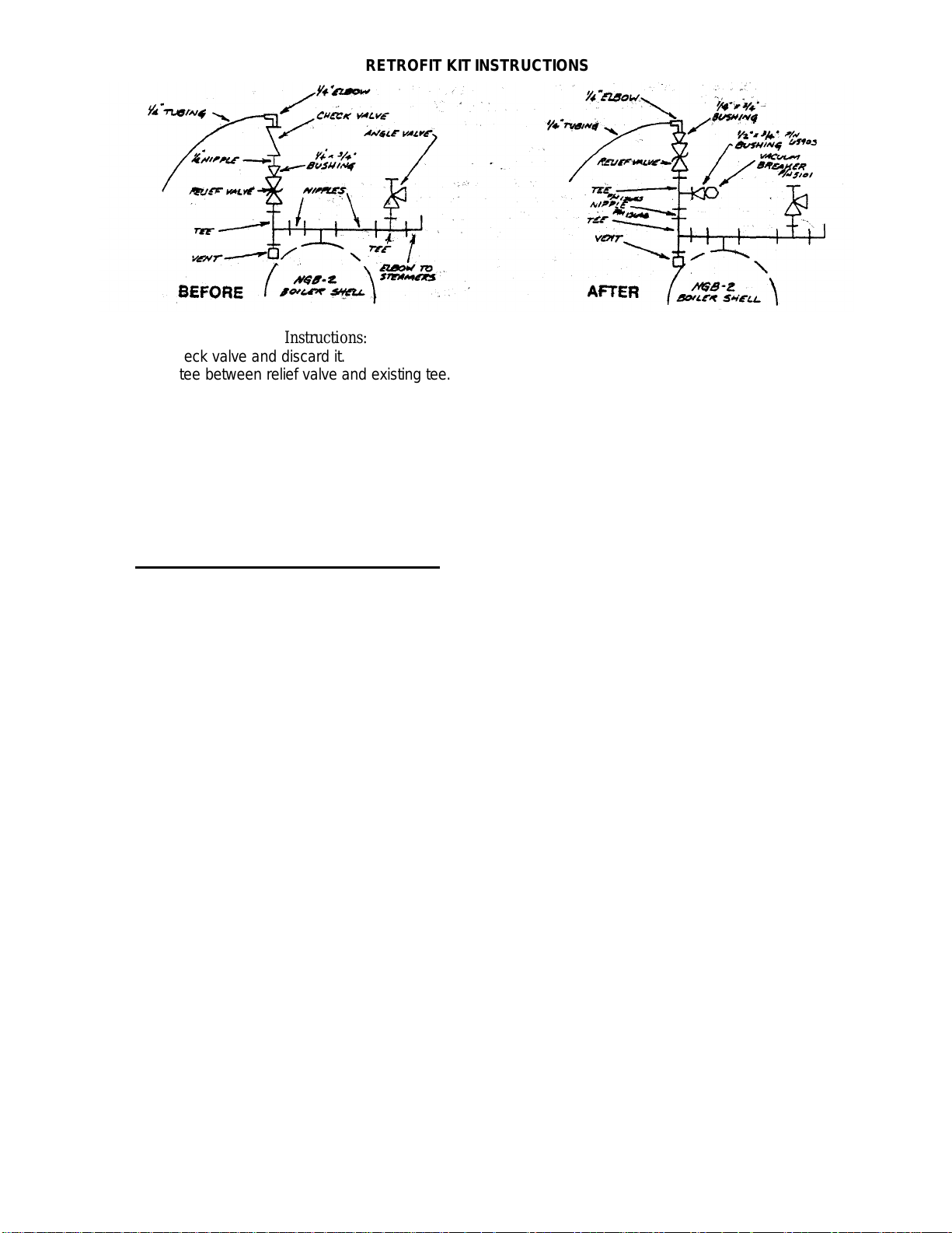
RETROFIT KIT INSTRUCTIONS
Instructions:
1. Remove check valve and discard it.
2. Place 3/4"'tee between relief valve and existing tee.
3. Screw reducing brushing and vacuum breaker into tee.
4. Screw 1/4 elbow into reducing bushing on relief valve.
Initial Start-Up
Now that the steam generator has been installed, the unit should be tested to ensure that it is
operating correctly.
For units made before August 8,1991:
1. Remove all literature and packing materials from the interior and exterior of the unit.
2. If no steam connections have been made, attach a hose to the steam outlet at the top of the
steam generator and pipe to a drain.
3. Open the main gas valve.
4. Before you fill the unit with water:
a. For NGB: Turn the knob on the gas valve to "PILOT", then push the knob in and hold it
while lighting the pilot burner. Continue to hold the knob in for 60 seconds, allowing the
thermocouple to heat up (this keeps the gas valve open).
b. For NGB/E: Turn the knob on the gas valve to the "ON" position.
c. For NGB/2: Turn the knob on the gas valve to "PILOT", then push the knob in and hold
it while lighting the pilot burner. Continue to hold the knob in for 60 seconds, allowing
the thermocouple to heat up, so it will keep the gas valve open.
d. For NGB/2/E: Turn the knob on the gas valve to the "ON" position.
5. For NGB or NGB/E:
Push the "ON/OFF" switch on the cabinet front panel to the "ON" position. The unit will
automatically fill with water. When the water level in the gauge glass reaches the full mark, wait
30 seconds, then push the "ON/OFF" switch to "RESET". The burner will then light. For NGB/2 or
NGB/2/E:
Push the "ON/OFF" switch on the cabinet front panel to the ON position. The red light in the
switch will come on, and the unit will automatically fill with water. When the water level in the
gauge glass reaches the full mark, the green "READY" light will come on. Push the "START"
switch. The amber light in the switch will come on. and the burner will light.
6. If connections to a steamer or a kettle have been made, check for steam by:
a. Turning on the steamer and checking for steam inside the cavity.
b. Filling the kettle with water, turning it on. and making sure that the water heats up.
If a hose connection (step "2" above) has been made, check for steam at the end of the
hose.
In all cases, steam should be detected within 20 minutes.
7. To shut down the unit push the "ON/OFF" switch to the OFF position. The generator will drain
automatically after it has cooled to 170°.
4
Page 7
For units made after August 7,1991:
Operation
1. Remove all literature and packing, materials from the interior and exterior of the unit.
2. Open the main gas valve.
3. Before you fill the unit with water:
a. For NGB/2 Turn the knob on the gas valve to "PILOT", then push the knob in and hold it while lighting
the pilot burner. Continue to hold the knob in for 60 seconds, allowing the thermocouple to heat up so it
will keep the gas valve open.
b. For NGB/2/E: Turn the knob on the gas valve to the "ON" position.
4. Push the "ON/OFF" switch on the cabinet front panel to the "ON" position. The red light in the switch will
come on, and the unit will automatically fill with water. When the water level in the gauge glass reaches
the full mark, the green "READY" light will come on. Push the "START" switch. The amber light in the
switch will come on, and the burner will light.
5. Check for steam at the drain (lower right corner as viewed from the rear). If connections to a steamer or a
kettle have been made, check for steam by:
a. Turning on the steamer and checking for steam inside the cavity.
b. Filling the kettle with water, turning it on, and making sure that the water heats up.
In all cases, steam should be detected within 20 minutes.
6. To shut down the unit, push the "ON/OFF" switch to the OFF position. The generator wiil drain
automatically after it has cooled to 170°.
If the generator functions as described above, the unit is ready for use. If it does not. contact your Groen Authorized
Service Agent.
A. Controls
The operating controls for NGB and NGB/E are:
1. The "ON/OFF" switch on the cabinet front panel. This control is used to call for electrical power to the unit
by pushing the switch to the "ON"; to light the unit by turning it to "RESET":to restart the unit in the event
that a low water condtion cuts off power to the gas valve (by turning to "RESET" again): and, finally, to turn
the unit off by turning the switch to "OFF".
2. The control knob on the gas valve. This control on the NGB is used in the "PILOT" position. when you are
lighting the pilot burner. Turning the knob to the "ON" position allows gas to flow through the valve to the
burner, and turning the knob to "OFF" cuts off the gas flow.
The operating control for NGB/2 and NGB/2/E are:
1. The "ON/OFF" switch on the cabinet front panel. This control is used to call for electrical power to the unit,
by pushing the switch to the ON position, and to shut down the unit, by pushing the switch to the OFF
position.
2. The "START" switch beside the "ON/OFF" switch. This control is used by briefly pushing the switch to the
"START" position. Using this switch lights the burner and also restarts the unit, if an electric power failure
or low water condition has cut off power to the gas valve.
3. The control knob on the gas valve. This control is used in the "PILOT" position (NGB/2 only), when you are
lighting the pilot burner. For either the NGB/2 or the NGB/2/E, turning the knob to the "ON" position allows
gas to flow through the valve to the burner. Turning the knob to "OFF" shuts off the gas flow.
5
Page 8
Operation (cont'd)
B. Operating Procedure
1. For Model NGB with standing pilot:
a. To light the pilot, turn the knob on the gas valve to "PILOT" and push it in. Hold the knob in
while lighting the pilot and for 50 seconds after the pilot is lit. Then turn the knob to "ON" and
the unit is ready to light. Do not attempt to light the main burners directly with a flame.
b. Push the "ON/OFF" switch to the "ON" position. The unit will automatically fill with water.
Wait 30 seconds after the water level reaches the full mark on the gauge glass. then push the
"ON/OFF" switch to "RESET". The unit will light.
c. If the pilot requires relighting, first turn the unit off and wait 5 minutes. Then follow the
instructions in step "a." above.
2. For Model NGB/E with Carborundum ignition coil:
a. The manual control knob on the gas valve must be in the "ON" position.
b. Push the "ON/OFF" switch to the "ON" position. The unit will automatically fill with water.
Wait 30 seconds after the water level reaches the full mark on the gauge glass, then push
the "ON/OFF" switch to "RESET". The unit will light.
3. For Model NGB/2 with standing pilot:
a. To light the pilot, turn the knob on the gas valve to "PILOT", then push the knob in and hold
it while lighting the pilot burner. Continue to hold the knob in for 60 seconds after the pilot is
lit. Then turn the knob to "ON". Do not try to light the main burners directly with a flame.
b. Push the "ON/OFF" switch on the cabinet front panel to the ON position. The red light in the
switch will come on, and the unit will automatically fill with water. When the water level in the
gauge glass reaches the full mark. the green "READY" light will come on. Push the "START"
switch. The amber light in the switch will come on. and the burner will light.
c. If the pilot goes out, first turn the unit off and wait 5 minutes, before you try to relight the
pilot. Then follow the operating instructions, beginning with step "a" above.
4. For Model NGB/2/E with electronic ignition:
a. Turn the knob on the gas valve to "ON".
b. Push the "ON/OFF" switch on the cabinet front panel to the ON position. The red light in the
switch will come on, and the unit will automatically fill with water. When the water level in the
gauge glass reaches the full mark, the green "READY" light will come on. Push the "START"
switch. The amber light in the switch will come on, and the burner will light.
5. To shut down any model:
a. Push the "ON/OFF" switch to the OFF position. When the generator has partially cooled,
the unit will drain automatically.
b. To shut down the unit completely, also turn the knob on the gas valve to the "OFF"
position.
6. For any model:
a. If electric power failure or low water condition has stopped operation, wait at least 5
minutes, then follow the operating procedure for your unit to restart it.
b. If generator pressure rises too far (over 14 PSI), the safety pressure switch will shut
off power to the controls. In this case, after waiting at least 5 minutes, restart the unit
by following the operating procedure for your unit, beginning with step "a".
If the pressure rises too high more than once, call your Groen Authorized Service Agency
6
Page 9

Sequence of Operation
A. For Model NGB or NGB/2
Pushing the power switch to the "ON" position will cause the water feed valve to open, filling the generator unit
until the level probe senses the proper water level. The feed valve will then close. At this time, momentarily
pushing the power switch to the "RESET" position Will open the gas valve. Gas flowing from the main burner will
be ignited by the standing pilot flame.
For units made before August 8,1991:
The gas valve will open at a gas pressure of 0.5 inch W.C. Within 15 seconds the pressure should reach 3.5
inches W.C. for natural gas or 10.0 inches W.C. for propane.
For units made after August 7,1991:
The valve will open at a gas pressure of 0.9 inch W.C. for natural gas or 2.5 inches W.C. for propane. Within 15
seconds the pressure should reach 3.5 inches W.C. for natural gas or 10.0 inches W.C. for propane.
The air vent is open at this point and will remain open until the temperature in the generator reaches 200°F. As
evaporation occurs in the generator and the water breaks from the probe, the water feed valve will open and the
20 second time delay will activate. If the water level fails to rise to the probe before the time delay times out, the
gas control valve will close and the controls will nave to be reset manually. In normal operation, the water level
will rise to the probe within the time delay period, and there will be no interruption in heating.
When pressure in the generator reaches 10 PSI, the operating pressure switch will cause the gas valve to close.
If residual heat makes the pressure rise to 12 PSI, the mid-range pressure switch will open both the condenser
water valve and the blow-down valve to decrease the pressure rapidly. As steam pressure decreases below 10
1/2 PSI. the mid-range switch will cause the condenser and blow-down valves to close. When the pressure falls to
9 PSI, the operating pressure switch will open the gas valve, and heating will resume. After this heating and
cooling cycle has been repeated once or twice, the generator will operate between 9 and 11 PSI, if no steam is
being drawn from it.
If steam pressure reaches 14 PSI. the high limit pressure switch will open and lock out the controls. When this
happens, the pilot lamp will go out. An open high limit switch must be reset manually to start the unit again.
Should the pressure exceed 15 PSI at any time. the safety valve will open and relieve excess pressure.
When the power switch is turned to the "OFF" position, the gas valve will close and the drain valve will open.
draining the unit completely.
B. For Model NGB/E or NGB/2/E
The sequence of events is the same as for Model NGB, with the following exceptions.
Pushing the power switch to the "RESET" position will activate the Carborundum ignition coil. The coil will heat to
a glowing temperature and cause the gas valve to open within approximately 12 to 20 seconds. Gas flowing from
the burner will be ignited by the coil. When the flame sensor detects a flame, the coil will] deactivate. If the sensor
ceases to sense a flame, the gas control valve will close and shut off the main burner. Then the coil will be
energized again and will relight the burner.
During normal operation, when steam pressure falls to 9 PSI, the operating pressure switch will activate the coil
and initiate the ignition sequence.
7
Page 10

Water Conditioning
It is absolutely essential that the water supplied to the Groen Steam-Generator be of such a character that it will not
form scale at an unacceptable rate. The Groen generator was engineered to minimize scale formation, but scale
formation depends on the hardness of the water and the hours of operation. In a few areas of the United States. the
water supply is sufficiently free of minerals to avoid scale formation. Most water supplies carry heavy loads or
minerals, which will form scale in the generator and reduce its steam output. Your local water utility can provide a
statement on the scale forming qualities of the water supply.
Water supplied to the steam generator should contain not more than 30 parts per million tote U. dissolved solids
(TDS) and should have a pH of 7.0 or higher. ,
Please follow these simple precautions:
(1) Do not rely on "water treaters" commonly sold as scale preventers and scale removers. THEY DO NOT
WORK. The only proven way to avoid scale build-up is to feed in water practically free of scale-forming
minerals.
(2) If your water supply carries scale forming minerals, as most water supplies do. run the feed water through a
properly maintained softener. Exchangeable softener cartridges or a regeneratable softener can be used. In
either case. establish a regular program of exchanging the cartridges or regenerating the softener. Installing a
water meter on the inlet line between the softener and the steam generator will give an accurate check of
water consumption and a way of determining when to change the cartridge or regenerate the softener. By
using a softener and operating within the softener's capacity to exchange minerals, the user will obtain a
longer generator life, high steam capacity, and minimum generator maintenance.
(3) If you notice a slowing of steam production, examine the interior of the generator for scale, and remove any
scale deposits. (See the general cleaning instructions.) Hard scale can be removed with acids like sulfamic or
inhibited muriatic, but such treatment is dangerous and should be done only by an expert familiar with the
hazards. Vinegar will dissolve most scales. but the process requires a long time and frequent changes of the
vinegar solution.
References
AMERICAN NATIONAL STANDARDS:
Z223.1-1984 National Fuel Gas Code
NATIONAL FIRE PROTECTION ASSOCIATION
60 Battery March Park
Quincy, Massachusetts 02269
NFPA.54 Installation of Gas Appliances & Gas Piping
NFPA.70 The National Electric Code
NFPA96 Ventilating Hoods
8
Page 11

Maintenance & Cleaning
The steam generator is designed to require minimum maintenance, but certain parts may need replacement after prolonged
use. After installation; no user adjustment should be necessary. If a service need arises, only authorized personnel should
perform the work.
WARNING: USE ONLY GROEN SUPPLIED PARTS. SUBSTITUTION OF UNAUTHORIZED PARTS OR GENERIC PARTS
WARNING: ELECTRIC POWER SHOULD ALWAYS BE SHUT OFF BEFORE ANY WORK IS DONE ON INTERNAL COM-
A. PERIODIC INSPECTION
It is recommended that service personnel check the unit at least once a year. This periodic maintenance should include
inspecting electrical wires and connections, cleaning the inside of the control console, and possible adjustment of the pilot
light or ignition coil.
A Maintenance and Service Log is provided with the warranty information. Each time maintenance is performed on your
Groen equipment, enter the date on which the work was done, what was done, and who did it. File the log with the warranty.
In addition to this yearly inspection, the following items should be checked weekly to ensure minimum equipment downtime
and to help guarantee efficient operation:
At least twice a month, check the safety valve to make sure that it works freely. When the gauge pressure is about 5 PSI, lift
the valve lever enough to vent steam, then quickly let it snap back into place.
WARNING: DO NOT EXPOSE YOURSELF TO THE ESCAPING STEAM. A SEVERE BURN CAN RESULT
ON EXPOSED SKIN.
CAN CAUSE BODILY INJURY TO THE OPERATOR AND DAMAGE TO THE EQUIPMENT.
PONENTS.
1. The pressure gauge should be in working order.
2. Water level in the steam generator should be between the lines on the level gauge glass.
3. The strainers in the drain and feed lines should be cleared.
4. Check the burner gas jet primary air inlets. They should be free from dirt and lint
5. The pilot light flame should be blue and envelop approximately 1/2 inch of the flame sensor tip (NGB only).
6. Check the drain for blockage. During operation there should be a continuous flow of water.
B. COMPONENT REPLACEMENT
The NGB and NGB/E steam generators are easy to service because of the accessibility of control components and simplicity
of design. An examination of the circuit diagram shows that. in most instances, a faulty component can be isolated with a
jumper wire.
Before replacing any part. COMPLETELY SHUT OFF THE GAS AND , ELECTRIC POWER SUPPLIES. Allow 5 minutes for
unburned gas to vent. When replacement involves breaking a gas pipe connection, check the new connection for leaks with a
thick soap solution or other appropriate leak detector. DO NOT USE A FLAME TO TEST FOR LEAKS.
All internal wiring is marked as shown on the circuit schematic drawing. Be sure new components are wired in the same
manner as the old components.
9
Page 12

Maintenance (cont’d)
C. GENERAL CLEANING INSTRUCTIONS
The steam generator will automatically drain completely .every .fine it is turned "OFF". This must be done every day
to minimize build-up of scale inside the boiler.
In addition to daily draining, once a month the following routine should be followed:
WARNING: BEFORE YOU BEGIN TO CLEAN THE UNIT, UNPLUG THE POWER SUPPLY CORD, OR
DISCONNECT THE ELECTRIC POWER SUPPLY AT THE CIRCUIT BREAKER OR FUSE BOX.
1. Turn the generator completely off, following the instructions on page 6.
2. Allow the generator to cool down.
3. Eliminate any remaining steam pressure by lifting the handle of the pressure relief valve.
4. Remove the brass plug from the front of the generator.
5. Open the manual drain valve.
6. Wash out the inside of the boiler with a water hose. The rinse water, along with the accumulated solids, will wash down
the drain.
7. Close the manual drain valve.
8. Replace the brass plug. Use pipe joint compound or Teflon tape on the threads to ensure a tight seal, and tighten the
brass plug securely.
CAUTION: AVOID DAMAGE TO ELECTRICAL COMPONENTS—DO NOT USE WATER OR STEAM
HOSE ON EXTERIOR OF UNIT.
As an alternative to the routine above, you may make the following steps
1. Turn the generator off and allow it to cool
2. Push the "ON/OFF" switch to "ON", so water will flow into the generator.
3. Open the manual drain valve and allow the unit to flush itself out for approximately 15 minutes.
4. Close the manual drain valve.
5. Turn the unit "OFF".
10
Page 13

Troubleshooting
That main water supply valve is open and water is
25
PSI.
The steam generator is designed to operate smoothly and efficiently if properly maintained. However, in the
event of a problem, the following list of checks maybe employed. If an item on the list is followed by an asterisk
(*);. the work should be done only by a. qualified service representative.
CAUTION: USE OF ANY REPLACEMENT PARTS OTHER THAN THOSE SUPPLIED BY GROEN OR THEIR
AUTHORIZED DISTRIBUTOR VOIDS ALL WARRANTIES, AND CAN CAUSE BODILY INJURY TO THE
OPERATOR AND DAMAGE TO THE EQUIPMENT. SERVICE PERFORMED BY OTHER THAN FACTORY
AUTHORIZED PERSONNEL WILL VOID ALL WARRANTIES.
NOTE: A wiring diagram is furnished on the inside of the cabinet door. The wiring of controls may be checked
against this diagram.
A. All models
SYMPTOM WHAT TO CHECK
Water does not enter generator.
a.
being supplied to the building.
b. Water switch to confirm it is on.
c. That electric power is on. Check main circuit
breaker or fuse and power supply to the building.
d. Strainer for build-up of solids.
e. For a defective water level control board (by
checking continuity) or for a loose connection (Ref.
22).'
f. For defective water feed solenoid valve. Check coil
for continuity, and replace, if defective (Ref. 36).*
g. Wiring for continuity."
h. For a defect in the ON/OFF switch (Ref. 3).'
i. Water level sensing probe for defect or sea's
accumulation. Clean or replace. if necessary (Ref.
6 or 38).*
Generator overfills with water.
a. Levelness of unit, by placing a spirit level on top of
the cabinet.
b. Water supply pressure may be too high. Adjust to
Generator underfills with water.
c. Water level control. Clean and adjust, if necessary
(Ref. 6 or 38).'
d. That water feed solenoid valve closes. Clean valve
seat and strainer, if necessary (Ref. 5 or 38).*
e. Water level control probe for a short (Ref. 6 or 38)'
a. Levelness of unit. by placing a spirit level on top of
the cabinet.
11
Page 14

demands of pressure switch have been met.
SYMPTOM.
Water enters generator very slowly.
WHAT TO CHECK
Strainer screen on water feed Solenoid valve,
a.
and clean or replace, if necessary (Ref. 6 or
38).*
Seat of feed valve for dirt or lime
b.
accumulation. Clean necessary (Ref.'6 or
Pressure of water supply. Adjust to 25-30
c.
PSI, if necessary-*
Indicator light does not come on when generator
is reset manually.
Water level. If it is low, wait for generator to
a.
till.
b. For defective indicator light (Ref. 2). *
Main burner will not light.
That main gas supply cock is open (handle is
a.
parallel to gas pipe) and that gas is being
supplied to the building.
Position of gas valve knob. See the "Opera-
b.
tion" section of this manual.
Electric power supply. Check main circuit
c.
breaker or fuse and confirm that power is being supplied to the building.
That there is water in the generator. If not,
d.
see "Symptoms: Water does not enter
generator."
Voltage at gas valve. If not correct, inspect
e.
wiring.*
Pressure switch. If set too low. reset. If con-
f.
tinuity check reveals a defect replace. (Ref.
23).*
g.
Gas valve and replace if defective. (Ref. 10).*
Generator fails to build up pressure when water
level is proper.
Position of gas valve knob. See "Operation"
a.
section or this manual.
Pressure gauge. Shut down generator and
b.
relieve all pressure. If gauge does not return
to zero, replace it. (Ref. 1).'
c. Air vent. and replace if defective (Ref. 4).*
Water level in gauge glass jumps up and
down,
Generator fails to cut off after reaching
operating pressure.
For insufficient flames or inadequate gas sup-
d.
ply. Adjust gas flow. (Ref, 10)*
Valve in sight gauge assembly. Make sure it
a.
is open.
Pressure gauge. Shut down generator and
a.
relieve all pressure. If the gauge does not
return to zero. replace it. (Ref. 1)'
Pressure switch. If set too high, adjust. If
b.
defective, replace. (Ref 23).*
That gas valve cuts off gas supply when
c.
If not, replace gas valve. (Per. 10).*
12
Page 15

SYMPTOM WHAT TO CHECK
Safety valve pops.
a
Confirm, that pressure gauge reads correctly.
Generator builds up pressure, shuts down. and fails to
come on again.
Generator cuts out after 10 to 15 minutes of
operation.
Air vent leaks. a.
Cold water condenser does not function.
Generator operates erratically. a.
Generator will not drain. a.
B. Model NGB Only
Pilot will not light.
(1) If pressure goes over 15 PSI, adjust or
replace pressure switches. (Ref. 23.24). * (2) If
pressure stays under 14 1/2 PSI: (a) Clean
safety valve. (b) Replace safety valve with valve
stamped "HV". (Ref. 5).*
If pressure gauge reads incorrectly, replace it
b.
(Ref. 1).*
a.
High limit switch. If set too low, adjust and reset.
If defective, replace. (Ref. 23 HI).*
b.
Operating pressure switch. If set too high, adjust.
If defective, replace. (Ref. 23 OP)*
Water level. If low, see "Symptoms" above:
c.
"Water does not enter generator" and "Water
enters generator very slowly."
a. Water level. If low, see "Symptoms" above:
"Water does not enter generator" and "Water
enters generator very slowly."
b.
Time delay relay. If defective, replace, (Ref. 28).-
c. Connections for time delay relay.'
Clean or replace vent. (Ref. 4).'
a.
Water supply, to confirm that it is on and the
pressure is 25 to 30 PSI.'
b. Condenser water feed valve. Check solenoid coil
for continuity, and replace if defective. (Ref. 37).*
c.
Y-strainer. Clean. if necessary.
Water pressure. So ensure it is 25 to 30 PSI.'
b.
For defective or clogged valves.*
Wiring connections."
c.
Drain valve and hose for clogging. Clean Ystrainer and valve. (Ref. 35).'
b. For defective drain valve.*
c
Wiring connections to drain valve."
That the main gas supply cock is on (handle
a.
parallel with gas pipe) and that gas is being
supplied to the building.
b. Position of gas valve knob. See "Operation"
section in this manual.
c.
Pilot gas line and orifice for obstructions (Ref. f7.)'
d. Pilot gas adjustment, and readjust, if necessary.
(Ref. 17.).*
e.
For loose or broken wires*
f. Thermocouple. (Ref. 15).*
13
Page 16

SYMPTOM WHAT TO CHECK
(Ref.
17
).*
Pilot light does not stay lighted.
Generator builds up pressure, shuts down, and fails to
come on again.
Main burners will not light.
C. Model NGB/Eonly
Glow coil does not heat.
a. Lighting procedure. See the "Operation" section of
this manual.
b. For defective switching across either the water
level control or the pressure switches by testing for
continuity. Replace defective units. (Ref. 22 or 23,
24).*
c. For defective gas valve and replace if necessary
(Ref. 10).*
d. Pilot gas adjustment and readjust, if necessary
a. Pilot light. If out. see "Operation" section of this
manual.
a. Pilot light. If it is out, see the "'Operation" section
of this manual.
b. Gas valve. Replace, if defective (Ref. 10).*
a. That electric power is being supplied to the unit.
b. For 115V input to the control module (Ref. 31)*
c. For a 24 V supply at the transformer (Ref. 31).'
d. For 24 V between pins "2" and "4" of the control
module (Ref. 25).'
e. Voltage of supply to the igniter by removing the
igniter plug from the receptacle of the control
module and reading voltage across the pins of the
igniter receptacle (Ref. 25).* If 115 V is not
present, replace the control module. (Ref. 25).*
Burner does not come on. but the glow coil
heats.
f. Voltage across the terminals of the main gas valve
solenoid. If 24 VAC is present. replace the gas
valve assembly. If not, replace the control module.
(Ref. 10 and 25)*
a. Voltage across the terminals of the gas valve
solenoid. If 24 VAC is present, replace the gas
valve assembly. If not, replace the control module.
(Ref. 10 and 25).*
b. Ground connections of module terminal. "12"
(green wire) for firm attachment (Ref. 25)*
c. Flame sensing probe and wire "11" (blue) for a
short to ground. If necessary, correct the short or
replace the probe (Ref. 20).*
d. For a short to ground at the 24 V source. If the
transformer is shorted, remove the short and
replace the control module. (Ref. 31 and 25).*
e. After the transformer has been replaced, check the
flame sensing function. If flame sensing is not
working. reverse the leads of either the 115 V or
24 V side of the control transformer (Ref. 20 and
31).*
14
Page 17

Parts List
To order parts, contact your authorized Groen Service Agency. Supply the model designation, part description, part
number, quantity, and where applicable, voltage and phase or type of gas.
ITEM PART ITEM PART
NO. NO. DESCRIPTION NO. NO. DESCRIPTION
1 59407 PRESSURE GUAGE 19 54285 COIL IGNITOR
2 2986 PILOT LAMP 20 64170 PROBE SENSING
3 26753 3 POSITION SWITCH 21 54284 BRACKET, COIL IGNITOR
4 84098 VENT, THERMOSTATIC 22 5958 BOARD, WATER LEVEL CONTROL
5 8639 SAFETY VALVE 15# 23 3860 CONTROL STEAM PRESSURE
6 14356 ELECTRODE WATER LEVEL (ser.* 119939 & under) 24 3861 CONTROL STEAM PRESSURE
7 54196 FITTINGS, SIGHT GLASS 25 76519 CARBORUNDUM CONTROL
8 8917 GASKET SIGHT GLASS 26 50728 BRACKET, CARBORUNDUM CONTROL
9 59899 GLASS TUBE 27 3442 RELAY, CONTROL
10 49274 VALVE GAS NAT. PILOT IGNITION 28 49980 RELAY, DELAY
50727 VALVE GAS NAT. COIL IGNITION 29 54281 TERMINAL BLOCK 18 TABS
50838 VALVE GAS PROPANE PILOT IGNITION 30 51716 TERMINAL BLOCK 12 TABS
50835 VALVE GAS PROPANE COIL IGNITION 31 3331 TRANSFORMER
11 47267 BURNER ASSY. NAT. GAS 32 5289 BOX, OUTLET
50491 BURNER ASSY. PROPANE GAS 33 9883 BALL VALVE 3/4"
12 56965 FLAME HOLDER 34 4181 STRAINER 1/213 50490 BRACKET BURNER MOUNTING 35 76637 SOLENOID VALVE 1/2"
14 49277 BURNER BAFFLE 36 11043 SOLENOID VALVE 1/2"
15 64164 THERMOCOUPLE 37 3460 SOLENOID VALVE 1/4"
16 54203 BRACKET PILOT ESSEX VALVE 38 60168 ELECTRODE WATER LEVEL (ser.# 119940 & up)
83059 BRACKET PILOT HONEYWELL VALVE 39 76502 CONTROL STEAM PRESSURE
17 64162 PILOT NAT. GAS 40 74966 CONTROL STEAM PRESSURE
64163 PILOT PROPANE GAS 41 74967 CONTROL STEAM PRESSURE
18 49863 RING RETAINING 42 76539 GROMMET, PRESSURE SWITCH
43 71534 SIGHT GLASS BULLSEYE
Page 18

Page 19

Parts List
To order parts, contact your authorized Groen Service Agency. Supply the model designation, part description, part
number, quantity, and where applicable, voltage and phase or type of gas.
ITEM PART ITEM PART
NO. NO. DESCRIPTION NO. NO. DESCRIPTION
1 000624 BUSHING REDUCING HEX. 1" x 3/4" NPT 46 065903 BUSHING REDUCING 3/4" x ½ NPT
2 002647 BUSHING REDUCING 1 /2" x 1" NPT 47 070691 TEE3/4"x1/2"x1/2"NPT
3 005539 NIPPLE 1" NPT x 2" LONG 48 074573 TEE 3/4" x 3/4" FPT x 3/4" MPT
4 005600 NIPPLE 1/2" NPT x 12" LONG 49 077976 TEE 3/4" x 3/8" x 3/4" NPT
5 008229 NIPPLE 3/4" NPT x 4" LONG 50 077977 NIPPLE 3/4" NPT x 7" LONG
6 008347 ELBOW 90° STREET 3/4" NPT 51 078617 RELIEF VALVE 3/4" 12 PSI
7 008506 PLUG PIPE SQ. HD. 1/2- NPT 52 084098 VENT-AIR 3/8" NPT
8 008507 PLUG PIPE SQ.HD.1" NPT 53 074849 FLUE STACK
9 008877 NIPPLE 1 /2" NPT x CLOSE 54 074850 BRACKET TOP FLUE STACK
10 009883 VALVE BALL 3/4" NPT S.S. 55 074851 BRACKET SIDE FLUE STACK
11 012791 ELBOW 45° STREET 1 /2" NPT 56 005445 NUT-HEX 1/4—20
12 026254 TEE 1" NPT SIDE OUTLET STEAMER 57 008072 NUT-HEX 1/4"-20
13 026452 NIPPLE 1/2" NPTx6-1/2" LONG 58 077985 SNAP-ACTION THERMOSTAT
14 049429 CONNECTOR MALE 1 /2" NPT x 1/4 TUBE COM. 59 071915 PLUG PIPE 1" NPT
15 074594 VALVE OLENOID 1 /2" NPTF 60 071534 SIGHT GLASS
16 077905 NIPPLE 3/4" NPT x 25" LONG 61 078000 PRESSURE GAUGE
17 077974 TEE SIDE OUTLET 1/2" NPT 62 077984 SWITCH ON/OFF
18 005126 UNION 1/4'NPT 63 077983 SWITCH MOMENTARY
19 005675 NIPPLE 11V NPT x 2" LONG 64 008639 SAFETY VALVE 15 PSI
20 005682 ELBOW 90° 1/4" NPT 65 056965 FLAME HOLDER
21 008337 NIPPLE 1/4" NPT X 1-1/2" LONG 66 049277B BAFFLE BURNER
22 012747 SYPHON PRESS. GA. TBE 1/4" NPT 67 050490 BRACKET BURNER SUPPORT
23 013207 TEE 1/4" NPT 68 047267 BURNER ASSY. W/JETS NATURAL
24 026514 TUBE 3/8" O.D.x 11" LONG 68A 050491 BURNER ASSY. W/JETS PROPANE
25 041508 NIPPLE 11V NPT x 3" LONG 69 054203 BRACKET PILOT MTG.
26 051766 ELBOW 90° STREET 11V NPT 70 077973 VALVE GAS 1 /2" x 1 /2" NATURAL
27 057218 ELBOW 90° 11V FPT x 3/8" TUBE COMP. 70A 082908 VALVE GAS 1/2"x 1/2" PROPANE
28 .074595 PRESS SWITCH 1/4-NPT 9-1/2 PSI 71 076423 THERMOCOUPLE 36" LONG
29 077980 PRESS SWITCH 1/4" NPT 14-1/2 PSI 72 076421 PILOT BURNER NATURAL GAS
30 078623 ELBOW 90° 11V MPT x 3/8" TUBE COMP. 72A 076422 PILOT BURNER PROPANE GAS
31 002665 PLUG PIPE SQ. HD. 3/8" NPT 73 078618 INSULATION BLOCK
32 004187 VALVE SWING CHECK 1/2" NPT 74 074842 RELAY SPDT
33 012762 NIPPLE 1 /2" NPT x CLOSE 75 009697 SCREW ROUND HD. #6-32 x 3/8" LG.
34 013197 BUSHING REDUCING 3/4' x 1/2" NPT 76 074840 BOARD ELECTRICAL COMPONENTS
35 040765 TEE REDUCING 1/2x1/2x3/8" NPT 77 011045 SCREW ROUND HD. #6-32 x 1/2" LG.
36 061468 ELBOW 90° UNION 1/2" NPT 78 074839 TRANSFORMER 120/208/240 VAC 50/60 Hz
37 077975 VALVE SOLENOID WATER FEED 79 011033 SCREW ROUND HD. #8-32 x 3/8" LG.
38 003458 BUSHING REDUCING 3/4" x 1 /4" NPT 80. 059931 SCREW THUMB #8-32 x 3/8" LONG
39 004306 NIPPLE 1/2" NPTXCLOSE 81 074596 BOX ELECTRICAL COMPONENTS
40 005101 VACUUM BREAKER 1/2" NPT 82 074597 COVER-BOX ELECTRICAL
41 007378 TUBING 11V O.D. x 28" LONG 83 009197 CORD GRIP 1 /2" NPT 5/16--3/8"
42 012849 VALVE ANGLE 1/2" NPT 84 004185 ELBOW 90° STREET 1 /2" NPT
43 013648 NIPPLE 3/4" NPT x CLOSE 85 005495 ELBOW 90° UNION 1 /2" NPT
44 013655 TEE 3/4" NPT 86 008227 NIPPLE 1/2"NPTx3-1/2"LONG
45 049296 ELBOW 1/4 MPT x 1/4 TUBE 87 008569 NIPPLE 1/2-NPTx4-1/2"LONG
Page 20

Page 21

Parts List
To order parts, contact your authorized Groen Service Agency. Supply the model designation, part description,
part number, quantity, and, where applicable, voltage and phase.
ITEM PART ITEM PART
NO. NO. DESCRIPTION NO. NO. DESCRIPTION
1 000624 BUSHING REDUCING HEX 1" X 3/4" NPT. 49 008239 NIPPLE 3/4" NPT X 3" LONG
2 002647 BUSHING REDUCING'/2" X 1" NPT. 50 077977 NIPPLE 3/4" NPT X 7" LONG
3 005517 NIPPLE 1/8" NPT CLOSE 51 078617 RELIEF VALVE 3/4" .12 PSI
4 005553 NIPPLE 1/2" NPT X 3" LONG 52 084098 VENT- AIR 3/8 NPT
5 010231 NIPPLE 3/4" NPT X1'/2 LONG 53 074849 FLUE STACK
6 008124 ELBOW 90° 3/4 NPT 54 074850 BRACKET TOP FLUE STACK
7 013202 NIPPLE BRASS 3/8 NPT X CLOSE 55 074851 BRACKET SIDE FLUE STACK
8 071915 PLUG PIPE SQ.HD. 1"NPT 56 005445 NUT-HEX 1/4"-20
9 064515 FITTING COMPRESSON — TUBING 57 008072 NUT-HEX 1/4"-20
10 009883 VALVE BALL 3/4" NPT SS 58 077985 SNAP-ACTION THERMOSTAT
11 086884 ELBOW 45° STREETS NPT 59 071915 PLUG PIPE 1" NPT
12 026254 TEE 1" NPT SIDE OUTLET STEAMER 60 071534 SIGHT GLASS
13 013648 NIPPLE 3/4 NPT X CLOSE 61 078000 PRESSURE GAUGE
14 086893 HOSE CONNECTORS NPT 3/4 I. D. HOSE 62 077984 SWITCH ON/OFF
15 074594 VALVE SOLENOID 1/2" NPTF 63 077983 SWITCH MOMENTARY
16 086897 NIPPLE 3/4" NPT X 153/4 LONG 64 090662 SAFETY VALVE 15 PSI
17 086898 "Y" 45° 3/4 NPT 65 056965 FLAME HOLDER
18 072242 TEE REDUCING BRASS 3/8 X 3/8 X 1/4 66 049277B BAFFLE BURNER
19 010873 HOSE CLAMP 67 050490 BRACKET BURNER SUPPORT
20 086900 HOSE RUBBER RADIATOR ¾ I,D. 68 047267 BURNER ASSY. W/JETS NATURAL
21 057217 FITTING 90° ELBOW COMP. 050491 BURNER ASSY. W/JETS PROPANE
22 091941 FITTING STRAIGHT COMP. 70 077973 VALVE GAS 1/2" X 1/2" NATURAL
23
24 090695 SIPHON PRESSURE SWITCH 72 076421 PILOT BURNER NATURAL GAS
25 090692 FITTING MALE RUN TEE % NPT MALE 076422 PILOT BURNER PROPANE GAS
26 090693 TUBE PRESSURE GAUGE 3/8 COPPER 74 074842 RELAYSPDT
27 057218 ELBOW 90° 1/4" FPT X 3/8" TUBE COMP. 75 009697 SCREW ROUND HD. #6-32 X 3/8 LG.
28 074595 PRESS. SWITCH 1/4" NPT 9 1/2 PSI 76 074840 BOARD ELECTRICAL COMPONENTS
29 077980 PRESS. SWITCH 1/4" NPT 14-1/2 PSI 77 088240 BUTTON PLUG.
30 091940 FITTING 90 DEG. COMP. 78 086892 TRANSFORMER 120/208/240 VAC 50/60 HZ
31 002665 PLUG PIPE SO. HD. 3/8" NPT 80 088239 GROMMET STRAIN RELIEF
32 004187 VALVE SWING CHECK 1/2" NPT 81 088250 BOX ELECTRICAL COMPONENTS
33 012762 NIPPLE 1/2" NPT X CLOSE 82 088251 COVER-BOX ELECTRICAL
34 013197 BUSHING REDUCING 3/4" X 1/2" NPT 83 001696 CORD GRIP 45°
35 040765 TEE REDUCING 1/2 X 1/2 X 3/8" 84 004185 ELBOW 90° STREET 1/2" NPT
36 061468 ELBOW 90° UNION 1/2 NPT 85 005495 ELBOW 90° UNION 1/2" NPT
37 084787 VALVE SOLENOID WATER FEED 86 008227 NIPPLE 1/2" NPT X 3-1/2"LONG
38 086887 BUSHING REDUCING 3/4" X 1/4" NPT 87 008569 NIPPLE 1/2" NPT X 4-1/2" LONG
39 086889 ELBOW 1/2 NPT 90° STREET 88 086894 HOSE CONNECTOR 1/2 NPT X 3/4 I.D
40 005101 VACUUM BREAKER 1/2" NPT 89 086843 RELAY TIME DELAY
41 007378 TUBING 1/4" O.D. X 30" LONG 90 084762 FUSE 3.2 AMP
42 012849 VALVE ANGLESNPT 91 045750 SEALTITE 3/8"
43 086886 TEE SIDE OUTLETS NPT 92 002944 FUSE HOLDER
44 008133 NIPPLE 3/4 NPT X 5" LONG 93 002945 FUSE 3 AMP SC TYPE
45 086896 REDUCING TEE 3/4 X 1 X 1 NPT 94 086890 BOX ENCLOSURE TRANSFOMER
46 086885 BUSHING REDUCING 3/4" X 1/2" NPT 95 086891 COVER BOX ENCLOSE
47 070691 TEE 3/4" X 1/2" X 1/2" NPT 96 076526 WATER LEVEL PROBE
48 074573 TEE 3/4" X 3/4" FPT X 3/4" MPT 97 072230 NIPPLE 1/2 NPT X 1 -1/2 LG. BRASS
090694
3/8 NPT MALE X 3/8 TUBE COMP. 69 054203 BRACKET PILOT MTG.
1/4 NPT MALE X 3/8 TUBE COMP. 082908 VALVE GAS 1/2" X 1/2" PROPANE
SIPHON PRESSURE SWITCH 71 076423 THERMOCOUPLE 36" LONG
X 3/8 TUBE COMP X 3/8 TUBE COMP. 73 005516 UNION 3/4 NPT.
1/4 NPT MALE X % TUBE COMP. 79 009696 SCREW ROUND HD. #8-32 X'/2"LG.
Page 22

For NGB/2 & NGB/2/E Made After August 7, 1991
Page 23

Electrical Schematics
For NGB/2 made between January 1,1988 and August 7, 1991
Page 24

Electrical Schematics
For NGB & NGB/E made before January 1,1988
Page 25

Wiring Ladder Diagrams
 Loading...