

Page 1
P IMPORTANT INFORMATION P KEEP FOR OPERATOR P IMPORTANT INFORMATION P
OPERATOR MANUAL OM-NFPC
Part Number 121009
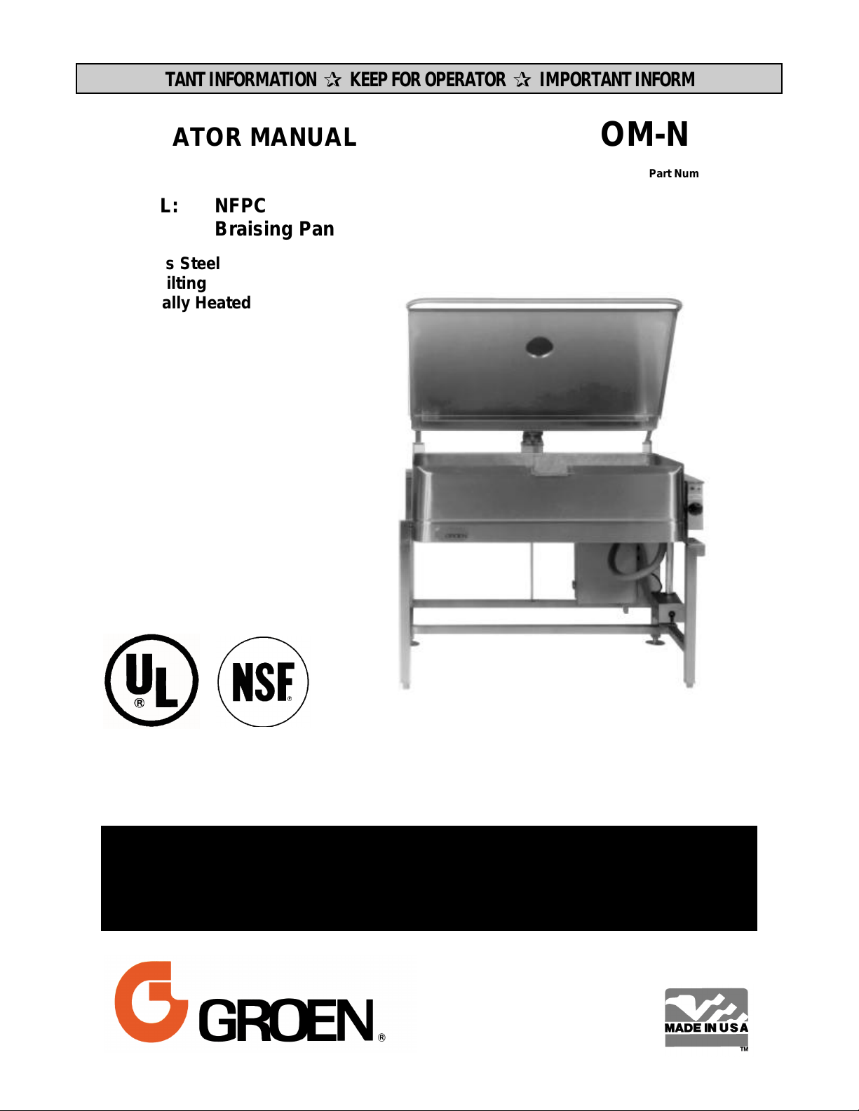
MODEL: NFPC
Braising Pan
Stainless Steel
Power Tilting
Electrically Heated
DOMESTIC
THIS MANUAL MUST BE RETAINED FOR FUTURE REFERENCE.
READ, UNDERSTAND AND FOLLOW THE INSTRUCTIONS AND
WARNINGS CONTAINED IN THIS MANUAL.
WARNING
DO NOT STORE OR USE GASOLINE OR OTHER FLAMMABLE
VAPORS AND LIQUIDS IN THE VICINITY OF THIS OR ANY OTHER
APPLIANCE.
.
Page 2
OM-NFPC
IMPORTANT — READ FIRST — IMPORTANT
CAUTION: BE SURE ALL OPERATORS READ, UNDERSTAND AND FOLLOW THE
OPERATING INSTRUCTIONS, CAUTIONS, AND SAFETY INSTRUCTIONS
CONTAINED IN THIS MANUAL.
WARNING: THIS UNIT IS INTENDED FOR USE IN THE COMMERCIAL HEATING,
COOKING AND HOLDING OF WATER AND FOOD PRODUCTS, PER THE
INSTRUCTIONS CONTAINED IN THIS MANUAL. ANY OTHER USE COULD
RESULT IN SERIOUS PERSONAL INJURY OR DAMAGE TO THE
EQUIPMENT AND WILL VOID WARRANTY.
CAUTION: ELECTRICALLY GROUND THE PAN AT THE TERMINAL PROVIDED.
WARNING: THE BRAISING PAN MUST BE INSTALLED BY PERSONNEL WHO ARE
QUALIFIED TO WORK WITH ELECTRICITY. IMPROPER INSTALLATION
COULD RESULT IN PERSONAL INJURY OR EQUIPMENT DAMAGE.
CAUTION: STAND AWAY FROM THE HOT WATER WHILE TILTING THE PAN TO
EMPTY IT.
WARNING: DO NOT HEAT AN EMPTY PAN FOR MORE THAN FIVE MINUTES AT A
SETTING HIGHER THAN 300o F.
WARNING: AVOID ANY EXPOSURE TO THE STEAM ESCAPING FROM THE COVER
VENT. DIRECT CONTACT COULD RESULT IN SEVERE BURNS
WARNING: AVOID ALL DIRECT CONTACT WITH HOT EQUIPMENT SURFACES. DIRECT
SKIN CONTACT COULD RESULT IN SEVERE BURNS.
WARNING: AVOID ALL DIRECT CONTACT WITH HOT FOOD OR WATER IN THE
BRAISING PAN. DIRECT CONTACT COULD RESULT IN SEVERE BURNS.
WARNING: IF THE PAN CONTAINS ITEMS IN SAUCE OR MELTED FAT, THEY COULD
SLIDE FORWARD SUDDENLY DURING TILTING AND CAUSE THE HOT
LIQUID TO SPLASH OUT.
WARNING: USE OF ANY REPLACEMENT PARTS OTHER THAN THOSE SUPPLIED BY
GROEN OR ITS AUTHORIZED DISTRIBUTORS VOIDS ALL WARRANTIES
AND MAY CAUSE BODILY INJURY AND/OR EQUIPMENT DAMAGE.
SERVICE PERFORMED BY OTHER THAN FACTORY AUTHORIZED
PERSONNEL WILL VOID ALL WARRANTIES.
WARNING: ALWAYS TURN OFF ELECTRIC POWER BEFORE WORKING ON INTERNAL
COMPONENTS.
WARNING: BEFORE ANY CLEANING OPERATION, TURN THE THERMOSTAT TO “OFF”
TO CUT OFF POWER TO THE HEATING ELEMENTS. BEFORE CLEANING
ANY PART OTHER THAN THE INSIDE OF THE PAN DISCONNECT THE
ELECTRICAL SUPPLY AT THE CIRCUIT BREAKER OR FUSE BOX.
WARNING: BE CAREFUL TO AVOID CONTACT WITH THE CLEANER IN ACCORDANCE
WITH SUPPLIER AND MANUFACTURER RECOMMENDATIONS. MANY
CLEANERS ARE HARMFUL TO THE SKIN, EYES, MUCOUS MEMBRANES
AND CLOTHING. READ THE WARNINGS AND FOLLOW DIRECTIONS ON
THE CLEANER LABEL.
CAUTION: NEVER LEAVE A CHLORINE SANITIZER IN CONTACT WITH STAINLESS
STEEL FOR LONGER THAN 30 MINUTES. LONGER CONTACT CAN CAUSE
CORROSION.
WARNING: DO NOT USE ANY FUSE WITH A HIGHER AMP RATING THAN THE RATING
SPECIFIED FOR THAT CIRCUIT.
2
Page 3
OM-NFPC
Table of Contents
IMPORTANT OPERATOR WARNINGS .................................................. 3
REFERENCES ...................................................................... 3
EQUIPMENT DESCRIPTION .......................................................... 4
INSTALLATION ..................................................................... 5
INITIAL START-UP .................................................................. 6
OPERATION ....................................................................... 6
SEQUENCE OF OPERATION .......................................................... 8
CLEANING ......................................................................... 9
MAINTENANCE .................................................................... 10
TROUBLESHOOTING ............................................................... 11
PARTS LISTS ..................................................................... 12
DIAGRAMS & SCHEMATICS ......................................................... 13
MAINTENANCE LOG ................................................................ 22
WARRANTY ....................................................................... 23
References
ECONOMICS LABORATORY, INC.
St. Paul, Minnesota 55102
NATIONAL FIRE PROTECTION ASSOCIATION
60 Battery March Park
Quincy, Massachusetts 02269
NFPA/70 The National Electrical Code
NATIONAL SANITATION FOUNDATION
3475 Plymouth Rd.
Ann Arbor, Michigan 48106
UNDERWRITERS LABORATORIES, INC.
333 Pfingsten Rd.
Northbrook, Illinois 60062
ZEP MANUFACTURING
1390 Lunt Avenue
Elk Grove Village, Illinois 60007
3
Page 4
OM-NFPC
Equipment Description
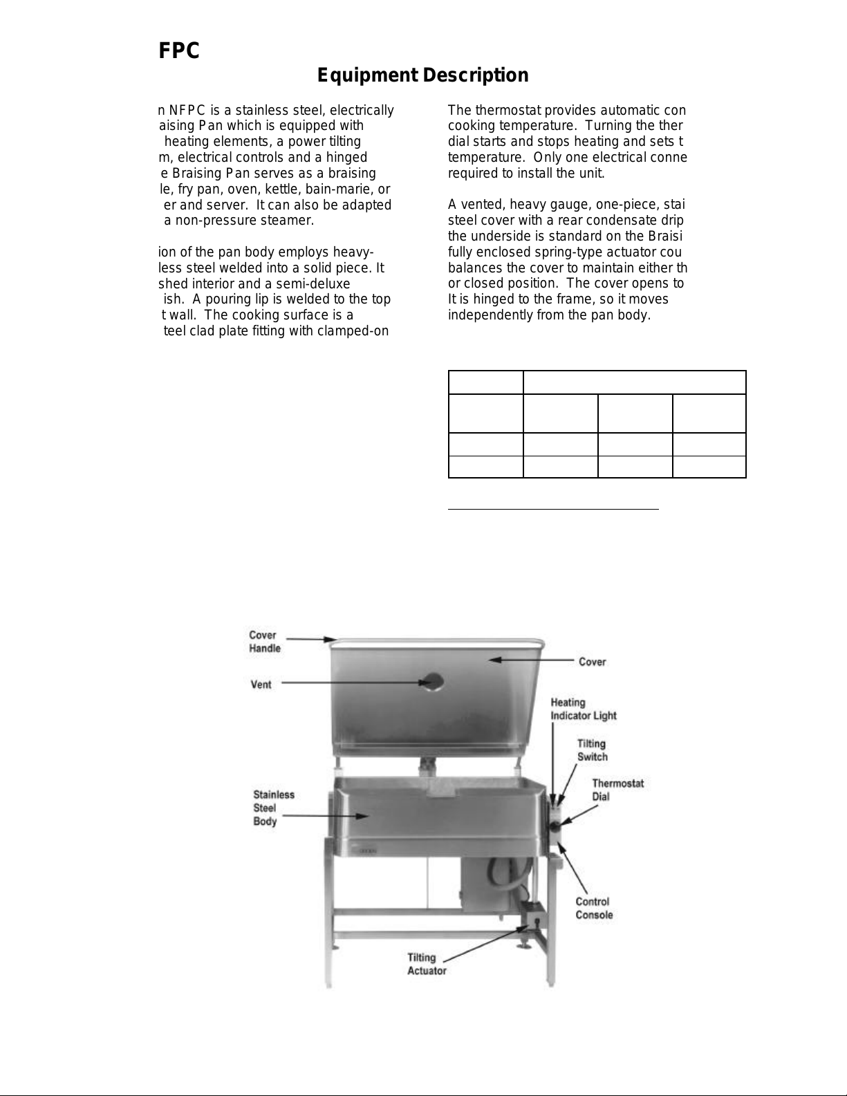
The Groen NFPC is a stainless steel, electrically
heated Braising Pan which is equipped with
integrated heating elements, a power tilting
mechanism, electrical controls and a hinged
cover. The Braising Pan serves as a braising
unit, griddle, fry pan, oven, kettle, bain-marie, or
food warmer and server. It can also be adapted
for use as a non-pressure steamer.
Construction of the pan body employs heavy-
duty stainless steel welded into a solid piece. It
has a polished interior and a semi-deluxe
exterior finish. A pouring lip is welded to the top
of the front wall. The cooking surface is a
stainless steel clad plate fitting with clamped-on
electrical heating elements. The elements are
positioned to ensure uniform heat transfer over
the entire surface. The pan is mounted on an
open-leg frame which is fabricated from tubular
stainless steel.
An electrically powered mechanism tilts the pan
forward. A three position switch on the front of
the control console gives the operator positive,
smooth-acting control of tilt.
Heating elements and other electrical
components are enclosed for safety. The
thermostat, heating indicator light, and tilting
switch are contained in a compact control
console which is mounted to the right of the pan
body.
The thermostat provides automatic control of
cooking temperature. Turning the thermostat
dial starts and stops heating and sets the pan
temperature. Only one electrical connection is
required to install the unit.
A vented, heavy gauge, one-piece, stainless
steel cover with a rear condensate drip shield on
the underside is standard on the Braising Pan. A
fully enclosed spring-type actuator counter
balances the cover to maintain either the opened
or closed position. The cover opens to the back.
It is hinged to the frame, so it moves
independently from the pan body.
The following models and options are available:
Model Pan Dimensions, Inches
Left to
Right
NFPC-3
NFPC-4
Optional Equipment (Either Model)
1. Fill faucet with swing spout and water hose
2. Model REJ Steamer Insert
3. Casters
31e 7 or 9 25¼
41e 7 or 9 25¼
Depth
Front to
Back
4
Page 5
Installation
OM-NFPC
Internal wiring for the Braising Pan is supplied
complete. When you receive it, the unit is ready
for connection. A wiring diagram is inside the
control box on the right side of the pan, as well
as in this manual (Pp 14-21). Your pan was
operated and tested at the factory to confirm that
all controls and heating elements were
functioning correctly.
Installation is as follows:
1. Set the unit in place and level it by turning
the adjustable feet. Make sure the tilting
mechanism has been rotated to its lowest
position and check levelness by placing a
spirit level on the bottom of the pan. The
unit must be level to avoid uneven cooking
across the pan.
2. At the electrical service entrance in the
bottom of the control box, make a
waterproof connection with the incoming
power line. A BX connection is not
recommended.
CAUTION
ELECTRICALLY GROUND THE PAN AT THE
TERMINAL PROVIDED.
3. Provide the proper electrical supply as
specified on the electrical plate attached to
the equipment. Observe local codes
and/or the National Electrical Code in
accordance with ANSI/NFPA 70 — latest
edition.
WARNING
THE BRAISING PAN MUST BE INSTALLED
BY PERSONNEL WHO ARE QUALIFIED TO
WORK WITH ELECTRICITY. IMPROPER
INSTALLATION COULD RESULT IN
PERSONAL INJURY OR EQUIPMENT
DAMAGE.
4. Any mechanical or electrical change must
be approved by the Groen Food Service
Engineering Department.
Voltage Phase
208 1 11.4 KW - 54.8 AMP 14.25 KW - 68.5 AMP
208 3 11.4 KW - 31.6 AMP 14.25 KW - 39.6 AMP
240 1 12 KW - 50 AMP 15 KW - 62.5 AMP
240 3 12 KW - 28.9 AMP 15 KW - 36.1 AMP
380 3 12 KW - 18.2 AMP 15 KW - 22.8 AMP
480 1 12 KW - 25 AMP 15 KW - 31.25 AMP
480 3 12 KW - 14.5 AMP 15 KW - 18 AMP
*All data at 60 Hz.
ELECTRICAL DATA*
Power and Current Draw
NFPC-3
Power tile motor draws 6 AMP at 120 Volts, Single Phase
NFPC-4
5
Page 6
OM-NFPC
Initial Start-Up
Now that the Braising Pan has been installed,
you should test it to ensure that it is operating
correctly.
1. Remove all literature and packing
materials from the interior and exterior of
the unit.
2. Turn on the electrical power to the unit.
3. Put enough water into the pan to cover its
bottom to a depth of ¼” to ½”. With the tilt
mechanism still cranked all the way back
to the horizontal position, note how the
water covers the pan bottom. This is a
good method to confirm that the unit is
properly leveled.
Operation
Operator Controls on the Braising Pan are the
thermostat dial and power tilt switch on the
console to the right of the pan body. The dial
turns electric power for the pan on or off, and
sets the pan’s operating temperature. The
power tilt switch is used to raise or lower the pan
body. Press the switch down to raise the pan
or up to lower it.
A. Start-up Procedure
4. Set the thermostat to 235o F. The heating
indicator light should come on to indicate
that the pan is heating. Heating should
continue until the water boils.
5. To shut the unit down, turn the thermostat
dial to “OFF.”
CAUTION
STAND AWAY FROM THE HOT WATER
WHILE TILTING THE PAN TO EMPTY IT.
6. Position a container for the pour-off and
press down on the power tilt switch so that
the water pours out. This will confirm that
the pan body can be tilted from horizontal
to vertical.
B. Cooking
1. To simmer or slowly heat an item, set the
dial at about 210o F or lower. Put the
cover down to keep moisture loss at a
minimum, or leave it up to help dry the
product. Set the thermostat higher to cook
or drive moisture off faster. The
thermostat may be adjusted to any setting
in its range to cook exactly as you wish.
1. Set the thermostat dial to the desired
temperature between 100 and 400o F. The
glowing Heat Indicator Light shows that
the pan is heating. When the light cycles
on and off, it indicates that the pan is being
held at the set temperature. Once in each
of these cycles you may hear the
contactors in the control box make a
clicking sound.
2. For best results when braising or frying,
preheat the pan before putting in any food.
For an even temperature across the pan,
reheat at a setting of 300o F or less for 15
minutes, or through several on/off cycles
of the thermostat.
WARNING
DO NOT HEAT AN EMPTY PAN FOR MORE
THAN FIVE MINUTES AT SETTINGS ABOVE
300oF. DAMAGE TO THE PAN COULD
RESULT.
2. Leave the cover vent open to allow excess
steam to escape. For longer simmering,
you may wish to close the vent.
WARNING
AVOID ANY EXPOSURE TO THE STEAM
ESCAPING FROM THE COVER VENT.
DIRECT CONTACT COULD RESULT IN
SEVERE BURNS
3. To check cooking progress when the
cover has been closed, grasp the plastic
handle of vent cover and lift it slightly while
moving it quickly to either side. Standing
at one side of the pan to avoid the steam
that will be released, grasp the nearest
corner of the cover handle and raise the
cover. The cover will stay in the open
position until you put it down.
6
Page 7
4. To pour or dump product, remove grease,
or assist cleaning, first raise the cover,
then tilt the pan up and forward by pushing
down on the power tilt switch. Whenever
you release the tilt switch the pan body will
hold its position.
OM-NFPC
5. To return the pan to the horizontal
position, pull the switch up.
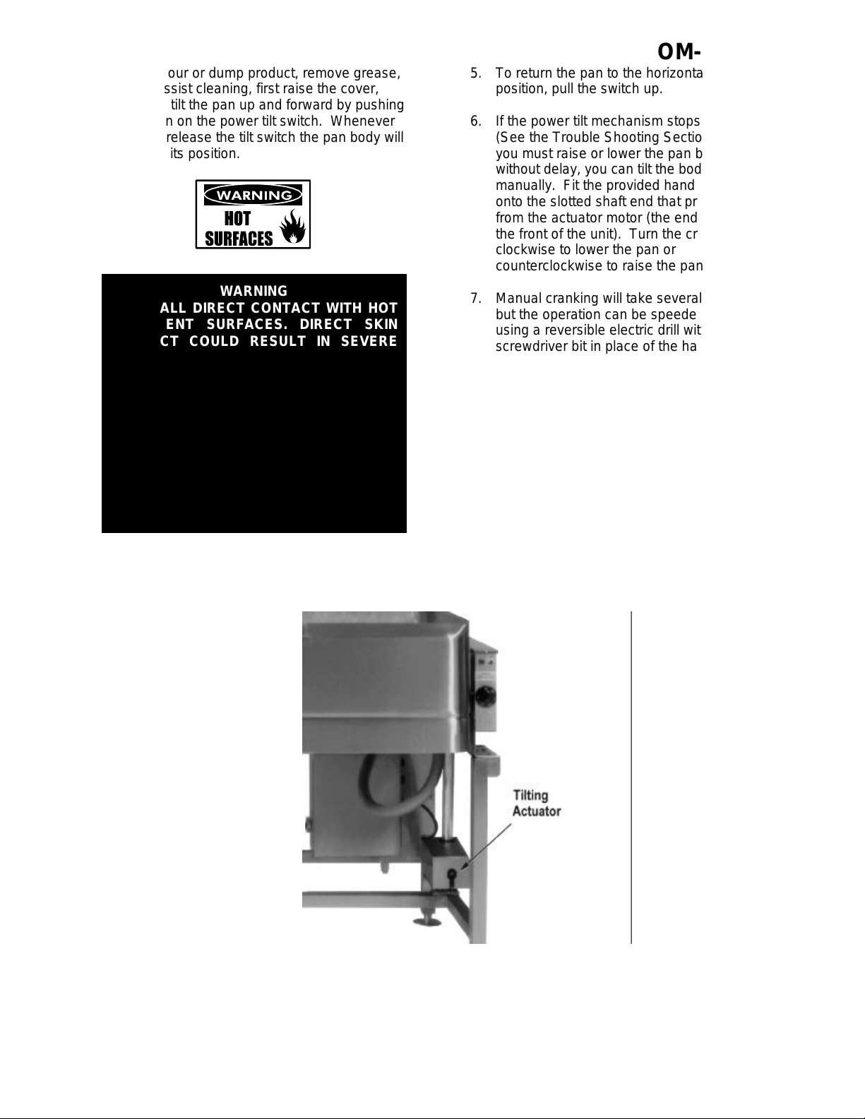
6. If the power tilt mechanism stops working
(See the Trouble Shooting Section) and
you must raise or lower the pan body
without delay, you can tilt the body
manually. Fit the provided hand crank
onto the slotted shaft end that protrudes
from the actuator motor (the end facing
the front of the unit). Turn the crank
clockwise to lower the pan or
counterclockwise to raise the pan.
WARNING
AVOID ALL DIRECT CONTACT WITH HOT
EQUIPMENT SURFACES. DIRECT SKIN
CONTACT COULD RESULT IN SEVERE
BURNS.
AVOID ALL DIRECT CONTACT WITH HOT
FOOD OR WATER IN THE BRAISING PAN.
DIRECT CONTACT COULD RESULT IN
SEVERE BURNS.
IF THE PAN CONTAINS ITEMS IN SAUCE OR
MELTED FAT, THEY COULD SLIDE
FORWARD SUDDENLY DURING TILTING
AND CAUSE THE HOT LIQUID TO SPLASH
OUT.
7. Manual cranking will take several minutes,
but the operation can be speeded up by
using a reversible electric drill with a
screwdriver bit in place of the hand crank.
C, Routine Clean Up
After each use, turn the thermostat to
“OFF” and clean all food contact surfaces
to ensure proper sanitation. At the end of
the day, or at least once every 24 hours,
turn off the heat and shut off electric power
to the unit and clean both the interior and
exterior of the pan. See Page 9 for more
detailed cleaning instructions.
The pan body may also be tilted manually using
a hand crank on the slotted shaft of the actuator
motor.
7
Page 8
OM-NFPC
Sequence of Operation
The following “action-reaction” outline is provided
to help you understand how the braising pan
actually functions.
When you start up the pan by turning the
thermostat from “OFF” to a desired temperature,
the thermostat switch closes. This causes the
contactors to close, and allows power to flow to
the heating elements and the indicator light.
When the pan temperature reaches the value
set on the thermostat dial, the thermostat switch
opens and causes the contactors to open. This
stops the flow of power to the heating elements
and the indicator light.
As soon as the thermostat senses that the pan is
cooling below the set temperature, the
thermostat closes, the contactors close, and the
heaters and indicator light come on again.
This on and off cycle continues, maintaining the
pan at the set temperature. This is why the
indicator light on and off cycling is seen during
normal operation.
The thermostat controls heating by alternating
between feeding full power and completely
cutting power off. The pan heats as fast as it
can until it reaches the set temperature, no
matter what that temperature is. Turning the
thermostat to a higher setting will cause heating
to continue longer, until the pan reaches a higher
temperature, but it cannot make the pan heat
any faster.
The power tilt switch controls a reversible motor
that drives a ball screw mechanism. When the
switch is held in the lowered position, the
mechanism raises the pan body. The body rests
on a trunnion near the front corners, so it tilts
forward until the switch is released or the body
reaches its vertical limit.
If the tilting motor gets too hot during operation,
an overheat protection switch will open and stop
the motor. When the motor has cooled
sufficiently, the switch will automatically reset
and permit tilting to begin again.
If the pan temperature exceeds 425o F for any
reason, a high-limit thermostat shuts off the
power until the pan cools. At that point, the
thermostat automatically resets to permit normal
operation to start again.
Turning the thermostat to “OFF” shuts down all
control and heating circuits.
8
Page 9

1. Suggested Tools
a. Cleaner, such as Klenzade HC-10
b. Brushes in good condition
c. Cloth for cleaning controls
d. Chlorine sanitizer such as Klenzade
XY-12
e. Heavy Duty Cleaner, such as Klenzade
LC-30
2. Procedure
WARNING
BEFORE ANY CLEANING OPERATION,
TURN THERMOSTAT DIAL TO “OFF” TO
CUT ANY POWER TO THE HEATING
ELEMENTS. BEFORE CLEANING ANY PART
OTHER THAN THE INSIDE OF THE PAN,
DISCONNECT ELECTRICAL SUPPLY AT
CIRCUIT BREAKER OR FUSE BOX.
OM-NFPC
Cleaning
Use a sponge, cloth or plastic brush to clean
the pan.
Scrapers or steel wool can harm the pan
surface.
a. Clean all food-contact surfaces soon after
use. It is best to clean the pan before it
has completely cooled. If the unit is in
continuous use, completely clean and
sanitize both the inside and outside at
least once every 12 hours.
CAUTION
KEEP WATER AND SOLUTIONS OUT OF
CONTROLS AND ELECTRICAL EQUIPMENT.
DO NOT SPRAY OR HOSE THE CONTROL
BOX OR OTHER ELECTRICAL
CONNECTIONS. THEY ARE NOT WATERPROOF.
b. To remove any large amount of food left in
the pan, tilt the pan all the way up and
flush it with lukewarm water. Do not
damage the surface of the pan by scraping
it with a metal tool.
CAUTION
MOST CLEANERS ARE HARMFUL TO THE
SKIN, EYES, MUCOUS MEMBRANES, AND
CLOTHING. PRECAUTIONS SHOULD BE
TAKEN. WEAR RUBBER GLOVES,
GOGGLES OR FACE SHIELD AND
PROTECTIVE CLOTHING. READ THE
WARNINGS AND CAREFULLY FOLLOW THE
DIRECTIONS ON THE CLEANER LABEL.
c. Following the supplier’s directions, make
up a warm solution of the cleaner.
Carefully wash the inside and outside of
the pan body with the cleaning solution.
d. Use a cloth moistened with cleaning
solution to clean controls, the control
console, and electric conduit.
e. Rinse the pan very well with lukewarm
water, and drain it completely.
f. As part of the daily cleaning program,
clean all inside and outside surfaces that
may have been soiled. Remember to
9
Page 10

OM-NFPC
check such parts as the undersides of the
cover, the electrical console and other more
remote spots. Clean between the pan
body and the control console using the
brush provided (P/N 058705).
g. To remove materials stuck to the
equipment, use a brush, sponge, cloth,
plastic or rubber scraper, or plastic wool
with the cleaning solution. To make
washing easier, let the cleaning solution sit
in the unit and soak into the residue, or
heat the solution briefly. Do not use any
gritty cleaner or metal tool that might
scratch the surface. Scratches make the
surface harder to clean, and also provide
places for bacteria to grow. Do not use
steel wool. Small bit of steel wool left in
the surface of the unit can cause rusting
and pitting.
h. The outside of the unit may be polished
with a recognized stainless steel cleaner
such as Zepper from the Zep
Manufacturing Company.
i. When the equipment needs to be
sanitized, use a sanitizing solution
equivalent to one that supplies 100 parts
per million available chlorine. Get advice
about the best sanitizing agent from you
supplier of sanitizing products. Following
supplier instructions, apply the sanitizing
agent after the unit has been cleaned and
drained. Thoroughly drain off the sanitizer.
CAUTION
NEER LEAVE A CHLORINE SANITIZER IN
CONTACT WITH STAINLESS STEEL
SURFACES FOR LONGER THAN 30
MINUTES. LONGER CONTACT CAN CAUSE
CORROSION.
j. After the unit has been cleaned, sanitized
and drained, let all surfaces air dry unless
the unit must be used again right away.
k. It is recommended that the unit be
sanitized just before use. Follow the
directions of the sanitizer supplier.
l. About once a week (more often if the
water is very hard), use a heavy duty
cleaner to remove any mineral deposits or
film left by hard water or foods. Follow the
supplier’s directions very carefully, and
rinse the unit off thoroughly as soon as
cleaning is finished.
m. If especially difficult cleaning problems
persist, contact your cleaning product
supplier for help. The supplier has a
trained technical staff with laboratory
facilities to serve you.
Maintenance
WARNING
USE OF REPLACEMENT PARTS OTHER THAN THOSE SUPPLIED BY GROEN OR THEIR
AUTHORIZED DISTRIBUTORS CAN CAUSE INJURY TO THE OPERATOR AND DAMAGE
TO THE EQUIPMENT AND WILL VOID ALL WARRANTIES. SERVICE PERFORMED BY
OTHER THAN FACTORY-AUTHORIZED PERSONNEL WILL VOID ALL WARRANTIES.
Your Braising Pan is designed to require
minimum maintenance, but certain parts may
require replacement after prolonged use. After
installation, no user adjustment should be
necessary. If a service need arises, only
authorized personnel should perform the work.
Service personnel should check the unit at least
once a year. This should include inspecting
electrical wires and connections and cleaning
inside of the control console. A Maintenance
and Service Log is provided at the rear of this
manual. Each time work is performed, enter the
date on which it was done, what was done, and
who did it.
ELECTRICAL POWER MUST BE SHUT OFF
BEFORE WORK IS DONE ON INTERNAL
COMPONENTS.
10
WARNING
Page 11

OM-NFPC
Troubleshooting
Your Groen Braising Pan will operate smoothly and efficiently if properly maintained. However, the
following is a list of checks to make in the event of a problem. If the actions suggested do not solve the
problem, call your qualified Groen Service Representative. For the phone number of the nearest agency,
call your area Groen representative or the Groen Parts and Service Department. If an item on the list is
followed by Y, the work should only be performed by a qualified service representative.
WARNING
USE OF ANY REPLACEMENT PARTS OTHER THAN THOSE SUPPLIED BY GROEN OR
THEIR AUTHORIZED DISTRIBUTORS CAN CAUSE INJURY TO THE OPERATOR AND
DAMAGE TO THE EQUIPMENT AND WILL VOID ALL WARRANTIES.
SERVICE PERFORMED BY OTHER THAN FACTORY-AUTHORIZED PERSONNEL WILL
VOID ALL WARRANTIES.
SYMPTOM WHO WHAT TO CHECK
xindicates items which must be performed by an authorized technician.
Pan will not heat, but
indicator light comes on.
Pan will not heat, and
indicator light will not
light
Pan continues to heat
after it reaches desired
temperature
Pan does not reach
desired temperature.
Rapid clicking noise
(chattering)
Uneven cooking due to
“hot spots.”
Uneven cooking due to
“cold spots.”
Pan will not tilt User a. That electrical power supply is on.
Auth Service
Rep Only
User a. That power supply is on.
Auth Service
Rep Only
User a. Thermostat dial setting
Auth Service
Rep Only
User a. Thermostat dial setting.
Auth Service
Rep Only
User a. For low voltage.
Auth Service
Rep Only
User a. That the pan body is level
Auth Service
Rep Only
Auth Service
Rep Only
a. Heating elements for short circuit.x
b. Fuses, accessible by removing caps on the side of the
control box.
c. For loose or broken wire.x
d. Thermostat functioning, by listening for a click when the
switch opens or closes.x
e. Contactor functioning.x
b. Thermostat functioning, by listening for a click when the
switch opens or closes.x
c. Thermostat calibration.x
d. Contactor, to determine if it is de-energized.x
b. Heating elements for ground short or open (burned out)
element.x
c. Thermostat functioning, by listening for a click when the
switch opens or closes.x
d. Thermostat calibration.x
e. Contactor functioning.x
b. Contactor for dirt or corrosion on the contacts.x
a. For open (burned out) heating element.x
b. For overheated actuator motor. Wait 15 minutes or less
for motor to cool, then operate the power tilt. (For
instructions on manual operation see Page 7.
c. For burned out capacitor or motor.x
11
Page 12

OM-NFPC
Parts List
Key Description Part No. Key Description Part No.
1 Control Box 050377 13 Actuator Cover Model 51 9"pan 014085
2 Thermostat 002180 14 Spring 012533
3 Switch, Toggle 002664 15 Cover Assembly, Vent 017494
4 Thermostat, High Limit 012840 16 Hinge Bracket 013485
5 Heater, Strip* — 17 Bracket 004556
6 Fuse, 6 Amp 003982 18 Actuator 045880
7 Fuse Holder 004326 19 Crank, Manual, Actuator 050242
8 Contactor (Units after 1/1/85) 006950 20 Thermostat Knob 003908
Contactor (Units pre-1/1/85)* — 21 Actuator Motor 054716
9 Indicator Light 002986 22 Support Pin 056909
10 Capacitor 050384 — Optional Spray Unit 003283
11 Transformer 051469 — Adapter 003284
12 Actuator Cover Model 51 7"pan 014052 *See Electrical Parts Chart
12
Page 13

OM-NFPC
ELECTRICAL PARTS CHART
(All data for 60 Hz)
Model Heater Contactor — See footnote
Quantity Part No. Quantity Part No.
NFPC-3
NFPC-3
NFPC-3
NFPC-3
NFPC-3 380V, 3PH 12 012843 1 013432*
NFPC-3
NFPC-3
NFPC-4
NFPC-4
NFPC-4
NFPC-4
NFPC-4 380V, 3PH 15 012843 1 013432*
NFPC-4
NFPC-4
*Before Jan 1, 1985. All units built after that date used Part No. 006950
208V, 1PH
208V, 3PH
240V, 1PH
240V, 3PH
480V, 1PH
480V, 3PH
208V, 1PH
208V, 3PH
240V, 1PH
240V, 3PH
480V, 1PH
480V, 3PH
12
12
12
12
12
12
15
15
15
15
15
15
012842
012842
012843
012843
012908
012908
012842
012842
012843
012843
012908
012908
1
1
1
1
1
1
1
1
1
1
1
1
006950
013432*
006950
013432*
013432*
013433*
006950
013432*
006950
013432*
013432*
013433*
Wiring Diagrams
For certain models of NFPC, all units manufactured after January 1, 1985, have been wired for three
phase power supply. The models affected are:
Size 3, 208 Volts Size 3, 240 Volts Size 4, 208 Volts Size 4, 240 Volts
If one of these Braising Pans will be used with single phase supply, it must be field converted as shown
below:
Phase Conversions for NFPC Sizes 3 and 4, 208
and 240 Volts manufactured after January 1, 1985.
13
Page 14

OM-NFPC
Wiring Diagrams
14
Page 15

Wiring Diagrams
OM-NFPC
15
Page 16

OM-NFPC
Wiring Diagrams
16
Page 17

Wiring Diagrams
OM-NFPC
17
Page 18

OM-NFPC
Wiring Diagrams
18
Page 19

Wiring Diagrams
OM-NFPC
19
Page 20

OM-NFPC
Wiring Diagrams
20
Page 21

Wiring Diagrams
OM-NFPC
21
Page 22

OM-NFPC
Service Log
Model No. Purchased From
Serial No. Location
Date Purchased Date Installed
Purchase Order No. For Service Call
Date Maintenance Performed Performed by
22
Page 23

OM-NFPC
Limited Warranty
To Commercial Purchasers *
(Domestic U.S., Hawaii &
Canadian Sales Only)
Groen Foodservice Equipment ("Groen Equipment") has been skillfully manufactured, carefully inspected and
packaged to meet rigid standards of excellence. Groen warrants its Equipment to be free from defects in
material and workmanship for (12) twelve months with the following conditions and subject to the following
limitations.
I. This parts and labor warranty is limited to Groen Equipment sold to the original commercial
purchaser/users (but not original equipment manufacturers), at its original place of installation in the
continental United States, Hawaii and Canada.
II. Damage during shipment is to be reported to the carrier, is not covered under this warranty, and is
the sole responsibility of purchaser/user.
III. Groen, or an authorized service representative, will repair or replace, at Groen's sole election, any
Groen Equipment, including but not limited to, draw-off valves, safety valves, gas and electric
components, found to be defective during the warranty period. As to warranty service in the territory
described above, Groen will absorb labor and portal to portal transportation costs (time & mileage)
for the first twelve (12) months from date of installation or fifteen (15) months from date of shipment
from Groen.
IV. This warranty does not cover boiler maintenance, calibration, periodic adjustments as specified in
operating instructions or manuals, and consumable parts such as scraper blades, gaskets, packing,
etc., or labor costs incurred for removal of adjacent equipment or objects to gain access to Groen
Equipment. This warranty does not cover defects caused by improper installation, abuse, careless
operation, or improper maintenance of equipment. This warranty does not cover damage caused by
poor water quality or improper boiler maintenance.
V. THIS WARRANTY IS EXCLUSIVE AND IS IN LIEU OF ALL OTHER WARRANTIES, EXPRESSED
OR IMPLIED, INCLUDING ANY IMPLIED WARRANTY OF MERCHANTABILITY OR FITNESS FOR
A PARTICULAR PURPOSE, EACH OF WHICH IS HEREBY EXPRESSLY DISCLAIMED. THE
REMEDIES DESCRIBED ABOVE ARE EXCLUSIVE AND IN NO EVENT SHALL GROEN BE LIABLE
FOR SPECIAL, CONSEQUENTIAL OR INCIDENTAL DAMAGES FOR THE BREACH OR DELAY
IN PERFORMANCE OF THIS WARRANTY.
VI. Groen Equipment is for commercial use only. If sold as a component of another (O.E.M.)
manufacturer's equipment, or if used as a consumer product, such Equipment is sold AS IS and
without any warranty.
* (Covers All Foodservice Equipment Ordered After October 1, 1995)
23
Page 24

1055 Mendell Davis Drive
Jackson, MS 39212
Telephone 601 372-3903 OM-NFPC (Revised 3/98)
FAX 601 373-9587 Part Number 121009
 Loading...