

Groen HY-6CAV Installation Manual
OPERATOR MANUAL
IMPORTANT INFORMATION, KEEP FOR OPERATOR
This manual provides information for:
MODEL HY-6CAV DOMESTIC
HYPLUS™
ATMOSPHERIC
STEAMER CAVITIES
· For Models: HY-6SM, HY-6SG, HY 6SE
· Capacity: 6 Steamer Pans (12” x 20” x 2-1/2”)
READY ON
WATER FILL
LOW WATER
HIGH PRESSURE
A
E
M
T
S
THIS MANUAL MUST BE RETAINED FOR FUTURE REFERENCE.
READ, UNDERSTAND AND FOLLOW THE INSTRUCTIONS AND
WARNINGS CONTAINED IN THIS MANUAL.
WARNING / FOR YOUR SAFETY
Do not store or use gasoline or other ammable vapors
and liquids in the vicinity of this or any other appliance.
WARNING
Improper installation, adjustment, alteration, service
or maintenance can cause property damage, injury or
death. Read the installation, operating and maintenance
instructions thoroughly before installing or servicing this
equipment.
It is the responsibility of the consignee to inspect the container upon receipt of
same and to determine the possibility of any damage, including concealed damage. Unified Brands suggests that if you are suspicious of damage to make a
notation on the delivery receipt. It will be the responsibility of the consignee to file
a claim with the carrier. We recommend that you do so at once.
Manufacture Service/Questions 888-994-7636.
Information contained in this document is known to be current and accurate at the time
of printing/creation. Unified Brands recommends referencing our product line websites,
unifiedbrands.net, for the most updated product information and specifications.
PART NUMBER 121001 REV D (10/10)
1055 Mendell Davis Drive
Jackson, MS 39272
888-994-7636, fax 888-864-7636
unifiedbrands.net

IMPORTANT - READ FIRST - IMPORTANT
WARNING: THE UNIT MUST BE INSTALLED BY PERSONNEL QUALIFIED TO WORK WITH ELECTRICITY AND
PLUMBING. IMPROPER INSTALLATION CAN CAUSE INJURY TO PERSONNEL AND/OR DAMAGE TO
THE EQUIPMENT. INSTALLATION MUST COMPLY WITH APPLICABLE CODES.
NOTICE: DO NOT INSTALL THE UNIT IN ANY WAY WHICH WILL BLOCK THE RIGHT SIDE VENTS, OR WITHIN
12 INCHES OF A HEAT SOURCE SUCH AS A BRAISING PAN, DEEP FRYER, CHAR BROILER OR
CONVECTION OVEN.
NOTICE: LEVEL THE UNIT FRONT TO BACK, OR PITCH IT SLIGHTLY TO THE REAR, TO AVOID DRAINAGE
PROBLEMS.
WARNING: TO AVOID DAMAGE OR INJURY, FOLLOW THE WIRING DIAGRAM EXACTLY WHEN CONNECTING A
UNIT.
CAUTION: DRAIN MUST BE RATED FOR BOILING WATER. DO NOT USE PLASTIC PIPE.
WARNING: DO NOT CONNECT THE DRAIN DIRECTLY TO A BUILDING DRAIN. DAMAGE TO THE EQUIPMENT MAY
RESULT.
WARNING: BLOCKING THE DRAIN MAY BE HAZARDOUS.
IMPORTANT: IMPROPER DRAIN CONNECTION WILL VOID WARRANTY.
WARNING: WHEN YOU OPEN A COMPARTMENT DOOR, STAY AWAY FROM STEAM COMING OUT OF THE UNIT.
CONTACT WITH STEAM CAN CAUSE BURNS.
WARNING: BEFORE CLEANING THE OUTSIDE OF THE STEAMER, DISCONNECT ELECTRIC POWER . KEEP
WATER AND CLEANING SOLUTIONS OUT OF CONTROLS AND ELECTRICAL COMPONENTS. NEVER
HOSE OR STEAM CLEAN ANY PART OF THE UNIT. SERIOUS INJURY COULD RESULT.
WARNING: LET COOKING CHAMBERS COOL BEFORE CLEANING. HOT SURFACES CAN CAUSE BURNS.
WARNING: CAREFULLY READ THE WARNINGS AND FOLLOW THE DIRECTIONS ON THE LABEL OF EACH
CLEANING AGENT USED. DIRECT CONTACT WITH SOME AGENTS CAN CAUSE INJURY.
WARNING: DO NOT MIX DE-LIMING AGENTS (ACID) AND DE-GREASERS (ALKALI) IN THE STEAM GENERATOR
OR ON THE COOKING CHAMBER WALLS. HARMFUL GASSES MAY RESULT.
WARNING: DO NOT PUT HANDS OR TOOLS INTO THE COOKING CHAMBER, UNTIL THE FAN HAS STOPPED
TURNING. THE ROTATING FAN CAN CAUSE INJURIES.
WARNING: DO NOT OPERATE THE UNIT UNLESS THE REMOVABLE RIGHT SIDE PANELS HAVE BEEN RETURNED
TO THEIR PROPER LOCATIONS. DAMAGE TO THE UNIT COULD OCCUR.
CAUTION: DO NOT LOCATE THE BOILER CABINET DIRECTLY OVER A FLOOR DRAIN OR FLOOR SINK. HUMIDITY
OR WATER FROM A DRAIN WILL DAMAGE ELECTRICAL PARTS OF A UNIT.
NOTICE: DO NOT USE CLEANING OR DE-LIMING AGENTS THAT CONTAIN SULFAMIC ACID OR ANY CHLORIDE,
INCLUDING HYDROCHLORIC ACID. IF THE CHLORIDE CONTENT OF ANY PRODUCT IS UNCLEAR,
CONSULT THE MANUFACTURER. DO NOT USE CLEANING OR DE-LIMING AGENTS THAT CONTAIN
MORE THAN 30% PHOSPHORIC ACID.
2 OM-HY-6CAV

IMPORTANT - READ FIRST - IMPORTANT
NOTICE: USE NO DE-GREASER THAT CONTAINS POTASSIUM HYDROXIDE OR SODIUM HYDROXIDE OR IS
ALKALINE.
WARNING: USE OF ANY REPLACEMENT PARTS OTHER THAN THOSE SUPPLIED BY GROEN OR THEIR
AUTHORIZED SERVICE AGENTS VOIDS ALL WARRANTIES AND CAN CAUSE BODILY INJURY TO THE
OPERATOR AND DAMAGE THE EQUIPMENT. SERVICE PERFORMED BY OTHER THAN FACTORYAUTHORIZED PERSONNEL WILL VOID ALL WARRANTIES.
DANGER: HIGH VOLTAGE EXISTS IN CONTROL COMPARTMENTS. DISCONNECT FROM BRANCH CIRCUIT
BEFORE SERVICING. FAILURE TO DO SO CAN RESULT IN SERIOUS INJURY OR DEATH.
OM-HY-6CAV 3

Table of Contents
Important Operator Warnings .................................................... page 2-3
References..................................................................................... page 4
Equipment Description................................................................... page 5
Installation ................................................................................. page 6-8
Initial Start-Up ............................................................................... page 9
Operation...................................................................................... page 10
Cleaning ........................................................................................ page 11
Maintenance.................................................................................. page 12
Troubleshooting ............................................................................ page 13
Parts List ................................................................................ page 14-20
Electrical Schematics ............................................................. page 21-23
Service Log .................................................................................. page 24
References
UNDERWRITERS LABORATORIES, INC.
333 Pngsten Road
Northbrook, Illinois 60062
KLENZADE SALES CENTER
ECOLAB, Inc.
370 Wabasha
St. Paul, Minnesota 55102
800 328-3663 or 612 293-2233
NATIONAL FIRE PROTECTION ASSOCIATION
60 Battery March Park
Quincy, Massachusetts 02269
NFPA/70 The National Electrical Code
NSF INTERNATIONAL
789 North Dixboro Road
P.O. Box 130140
Ann Arbor, Michigan 48113-0140
4 OM-HY-6CAV
Equipment Description
THIS OPERATOR MANUAL APPLIES
ONLY TO THE CAVITIES (COOKING
CHAMBERS) OF YOUR HY-6S SERIES
HYPLUS CONVECTION STEAMER. REFER
TO SEPARATE BOILER UNIT MANUAL
PROVIDED WHERE APPROPRIATE — OM-
CNGB/3 FOR HY-6SG, AND OM-CNEB/1 FOR
HY-6SE. THERE IS NO SEPARATE MANUAL
FOR THE HY-6SM DIRECT STEAM MODEL.
WARNING
THE UNIT MUST BE INSTALLED BY
PERSONNEL WHO ARE QUALIFIED TO WORK
WITH ELECTRICITY AND/OR GAS, AND
PLUMBING. IMPROPER INSTALLATION CAN
CAUSE INJURY TO PERSONNEL AND/OR
DAMAGE TO THE EQUIPMENT. THE UNIT
MUST BE INSTALLED IN ACCORDANCE WITH
ALL APPLICABLE CODES.
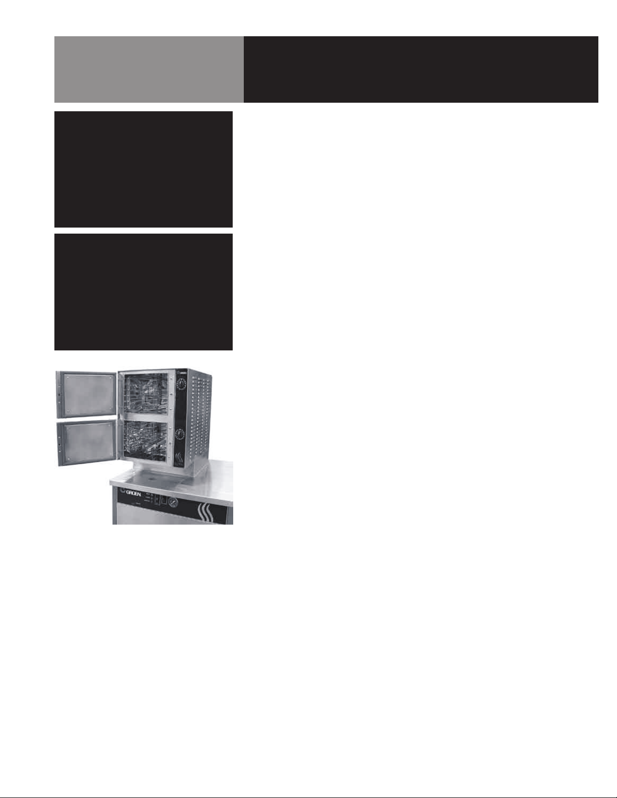
The Groen HY-6 HyPlus Steamer is designed to bring you years of service. It has
two stainless steel cavities (cooking chambers) and a control compartment, which
houses the electrical components and steam valves. In each cavity, a powerful blower
circulates the steam for increased heating efficiency. Each cavity will hold up to three
steam table pans (12” x 20” x 2-1/2”).
A 16 gauge stainless steel case encloses the cavities and the control compartment
that house electrical components. The door hinges are reversible (the doors may be
hung to open from the left or right).
Operator Controls are located on the front panel.
Model HY-6 HyPlus steamer cavities are mounted on a cabinet base and require a low
pressure (3-15 PSI) steam supply. Models HY-6SG and HY-6SE have steam boilers
(gas-fired or electrically heated, respectively) built into their cabinet bases. Model
HY-6SM has no steam generator and requires a “clean” steam supply suitable for food
contact.
The drain system includes a spray condenser, which suppresses any steam escaping
from the chamber and cools condensate water going into the drain.
HyPlus S Series steamers have two steam
compartments with individual controls.
OM-HY-6CAV 5

Installation
WARNING
THE UNIT MUST BE INSTALLED BY
PERSONNEL WHO ARE QUALIFIED TO
WORK WITH ELECTRICITY AND PLUMBING.
IMPROPER INSTALLATION CAN CAUSE
INJURY TO PERSONNEL AND/OR DAMAGE TO
THE EQUIPMENT. THE UNIT MUST BE
INSTALLED IN ACCORDANCE WITH ALL
APPLICABLE CODES.
CAUTION
SHIPPING STRAPS ARE UNDER TENSION.
THEY CAN SNAP BACK VIOLENTLY AND
CAUSE INJURY WHEN CUT.
CAUTION
MAKING ELECTRICAL OR MECHANICAL
CHANGES TO THE UNIT WITHOUT APPROVAL
FROM THE GROEN FOOD SERVICE
ENGINEERING DEPARTMENT MAY VOID
WARRANTIES.
PLEASE REFER TO THE APPROPRIATE
OPERATOR MANUAL (OM-CNGB/3 OR OM-
CNEB/1) FOR MODELS HY-6SG AND HY-6SE
STEAM BOILER INSTALLATION.
Immediately inspect the unit for external and internal damage when it is delivered.
Report any damage to the carrier. After inspection, keep the unit in its shipping
container until it is ready to be installed. The unit must be installed level. Level the unit
front to rear and left to right, by adjusting its feet. Check for levelness by using a spirit
level on top of the cabinet, and checking in both directions.
The HY-6SG Gas Model is suitable for installation on combustible and noncombustible
floors. Minimum installation clearances for the HY-6SG are:
Right Side 2 inches
Left Side 4 inches
Rear 6 inches
HY-6SE and HY-6SM models have no minimum clearance requirements, but room
should be provided so that the units may be serviced. The use of approved flexible
tubing and quick disconnect attachments will be helpful in allowing the unit to be
moved. For example, 24 inches right side clearance is needed for proper servicing,
unless the unit can be easily moved.
1. Electrical Supply Connection
A. On models HY-6SG and HY6-SE, power is supplied to cavity controls
and blower from the boiler base, and no other electrical connections are
required.
B. On model HY-6SM, you must provide 115 Volt Alternating Current, 60 Hz,
single phase, 15 AMP service. Local codes and/or the National Electrical
Code should be observed in accordance with ANSI/NFPA-70-1987 (or latest
edition). AN ELECTRICAL GROUND IS REQUIRED.
C. The electrical schematic is located in the electrical enclosure and in
this manual. In Canada provide electrical service in accordance with the
Canadian Electrical Code, CSA C22.1, Part 1 and/or local codes.
2. Water Supply Connection
A. Models HY-6SG and HY-6SE feature two separate water inlets – one for the
steam boiler (treated water), the other for the spray condenser (untreated
water). The second intake will reduce treatment requirements resulting in
significant savings.
B. For the HY-6SM, provide a 3/8” NPT pipe connection for untreated water
at the rear of the unit. A back siphonage device (check valve) must be
installed, complying with local plumbing codes. The water pressure should
be between 30 and 60 PSI (210 to 410 kPa). A pressure regulator is
required above 60 PSI (410 kPa).
C. The condenser spray uses 0.70 to 0.95 gallons of water per minute (2.6 to
3.6 liters per minute) at 30 to 60 PSI (210 and 410 kPa). The spray will only
operate when a steamer cavity (cooking chamber) is in operation.
6 OM-HY-6CAV
Installation
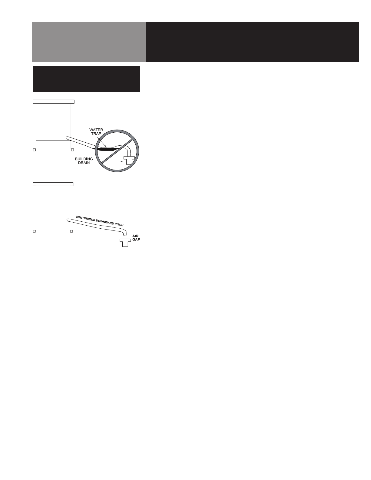
IMPORTANT
IMPROPER DRAIN CONNECTION
WILL VOID WARRANTY.
Leave an air gap between the hose
and the building drain, and don’t
allow water traps in the line.
D. Water supply lines should be sized to provide for maximum water use (the
total of the boiler and condenser spray) as shown in the following table:
Maximum Water Consumption-gal/hr (L/hr)
CNGB/3 boiler only 12.9 (48.8)
CNEB/1 (24KW) boiler only 8.2 (31.0)
CNEB/1 (36KW) boiler only 12.5 (47.3)
CNEB/1 (48KW) boiler only 16.9 (64.0)
HY-6 HyPlus Steamer condenser spray only
AT 40 PSI (280 kPa) 47.4 (180)
AT 60 PSI (410 kPa) 57.0 (215)
3. Drain Connection
A. On all HyPlus models (HY-6SG, HY-6SE and HY-6SM), the drain connection
is made at the rear of the unit, using a 1-1/4” NPT pipe. Do NOT use plastic
pipe — the piping must be able to withstand steam and hot water. Extend
the drain piping to a nearby floor drain. Piping of 1 - 1/4” NPT (or 1 - 1/2”
NPT) is acceptable for distances of six feet or less. If the distance to the
drain is further than six feet, use 2” NPT piping.
B. Install the drain line with a constant downward pitch. Do not allow any
water traps in the line. A trap can cause pressure to build up inside the
cavity during steaming, which will make the door gasket leak. A vertical
air gap must be maintained between the drain line and the building drain,
unless otherwise specified by local plumbing codes.
OM-HY-6CAV 7
Installation
IMPORTANT
REFER TO THE APPROPRIATE BOILER
MANUAL FOR COMPLETE INSTALLATION
DETAILS (OM-CNGB/3 FOR HY-6SG,
AND OM-CNEB/1 FOR HY-6SE)
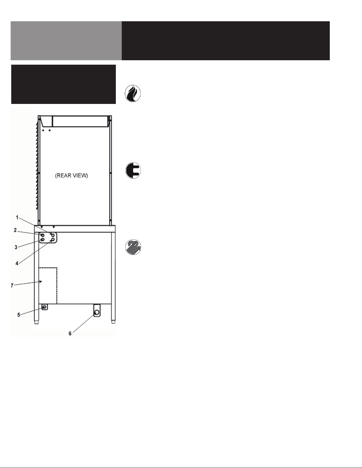
4. Utility Connection
A. HY-6SG (GAS) MODEL
1. Hot water (for faucet on 36” and wider units with kettles).
2. Steam outlet (for power take-off).
3. Cold water (treated).
4. Cold water (untreated).
5. Gas, natural or propane.
6. Drain (for boiler, steamers and condenser spray). Also for kettle
condensate and sink where used.
7. Electrical (conduit through underside, terminals at the right on the
inside).
B. HY-6SE (ELECTRIC) MODEL
1. Hot water (for faucet on 36” and wider units with kettles).
2. Steam outlet (for power take-off).
3. Cold water (treated).
4. Cold water (untreated).
5. Not used.
6. Drain (for boiler, steamers and condenser spray). Also for kettle
condensate and sink where used.
7. Electrical (conduit through underside, terminals at the right on the
inside).
C. HY-6SM (DIRECT STEAM) MODEL
1. Hot water (for faucet on 36” and wider units with kettles).
2. Steam inlet.
3. Cold water (for faucet on 36” or wider units with kettles.
4. Cold water (for condenser spray).
5. Not used.
6. Drain (for steamers and condenser spray). Also for kettle condensate and
sink where used.
7. Electrical (conduit through underside, terminals at the right on the
inside).
8 OM-HY-6CAV
Initial Start-Up
WARNING
STAY AWAY FROM STEAM COMING OUT
FROM THE UNIT. STEAM CAN CAUSE
SEVERE BURNS.
Once the unit has been installed, test it to be sure that the unit is working correctly.
1. Remove any literature and packing material from both the interior and the
exterior of the unit.
2. Make certain that the water supply is open.
3. Turn on the electrical power to the unit.
4. On models HY-6SG and HY-6SE, start the boiler and allow steam pressure to
develop. Refer to the Operator Manual OM-CNGB/3 or OM-CNEB/1, respectively)
for instructions on operating steam boilers. On model HY-6SM, turn on the steam
supply. Do not allow pressure to exceed 15 PSI.
5. When steam is available for the cavity, choose one of the following:
a. Set the timer to the desired time for timed steaming.
b. Turn the timer to the manual ON position for continuous steam.
NOTE: The door must be shut before steam will enter the cavity. If the door is
opened when the timer is on, the flow of steam will stop.
c. Let the steamer sit idle until needed.
6. If the unit will not be used for an extended period, turn off power to the individual
steamer compartments. Turn off power to the gas or electric pressure boiler.
Refer to the steam boiler operator manual, if necessary.
If the unit functions as described above, it is ready for use. If it does not, contact your
Groen Authorized Service Agent.
OM-HY-6CAV 9
 Loading...