

Page 1
OPERATOR MANUAL
IMPORTANT INFORMATION, KEEP FOR OPERATOR
This manual provides information for:
MODEL HY-5G & (2)HY-5G
HYPERSTEAM™
ATMOSPHERIC
CONVECTION STEAMER
· Self Contained
· Gas
· Capacity: 5 Steamer Pans [per cavity] (HY-5G) (12” x 20” x 2-1/2”)
THIS MANUAL MUST BE RETAINED FOR FUTURE REFERENCE.
READ, UNDERSTAND AND FOLLOW THE INSTRUCTIONS AND
WARNINGS CONTAINED IN THIS MANUAL.
WARNING / FOR YOUR SAFETY
Do not store or use gasoline or other ammable vapors
and liquids in the vicinity of this or any other appliance.
POST IN A PROMINENT LOCATION
Instructions to be followed in the event user smells
gas. This information shall be obtained by consulting
your local gas supplier. As a minimum, turn o the gas
and call your gas company and your authorized service
agent. Evacuate all personnel from the area.
WARNING
Improper installation, adjustment, alteration, service
or maintenance can cause property damage, injury or
death. Read the installation, operating and maintenance
instructions thoroughly before installing or servicing this
equipment.
NOTIFY CARRIER OF DAMAGE AT ONCE
It is the responsibility of the consignee to inspect the container upon receipt of
same and to determine the possibility of any damage, including concealed dam-
age. Unied Brands suggests that if you are suspicious of damage to make a
notation on the delivery receipt. It will be the responsibility of the consignee to le
a claim with the carrier. We recommend that you do so at once.
Manufacture Service/Questions 888-994-7636.
Information contained in this document is known to be current and accurate at the time
of printing/creation. Unified Brands recommends referencing our product line websites,
unifiedbrands.net, for the most updated product information and specifications.
PART NUMBER 142113 REV G (03/16)
1055 Mendell Davis Drive
Jackson, MS 39272
888-994-7636, fax 888-864-7636
unifiedbrands.net
Page 2

IMPORTANT - READ FIRST - IMPORTANT
WARNING: THE UNIT MUST BE INSTALLED BY PERSONNEL QUALIFIED TO WORK WITH ELECTRICITY AND
PLUMBING. IMPROPER INSTALLATION CAN CAUSE INJURY TO PERSONNEL AND/OR DAMAGE TO
THE EQUIPMENT. THE UNIT MUST BE INSTALLED IN ACCORDANCE WITH APPLICABLE CODES.
CAUTION: SHIPPING STRAPS ARE UNDER TENSION AND CAN SNAP BACK WHEN CUT.
CAUTION: DO NOT INSTALL THE UNIT IN ANY WAY WHICH WILL BLOCK THE SIDE VENTS, OR WITHIN 12
INCHES OF A HEAT SOURCE SUCH AS A BRAISING PAN, DEEP FRYER, CHAR BROILER OR KETTLE.
CAUTION: LEVEL THE UNIT FRONT TO BACK, OR PITCH IT SLIGHTLY TO THE REAR, TO AVOID DRAINAGE
PROBLEMS.
WARNING: FOLLOW THE WIRING DIAGRAM EXACTLY WHEN CONNECTING A UNIT TO AVOID DAMAGE OR
INJURY. WIRING DIAGRAM IS LOCATED ON THE INSIDE OF THE RIGHT PANEL.
CAUTION: DO NOT USE PLASTIC DRAIN PIPE. DRAIN MUST BE RATED FOR BOILING WATER.
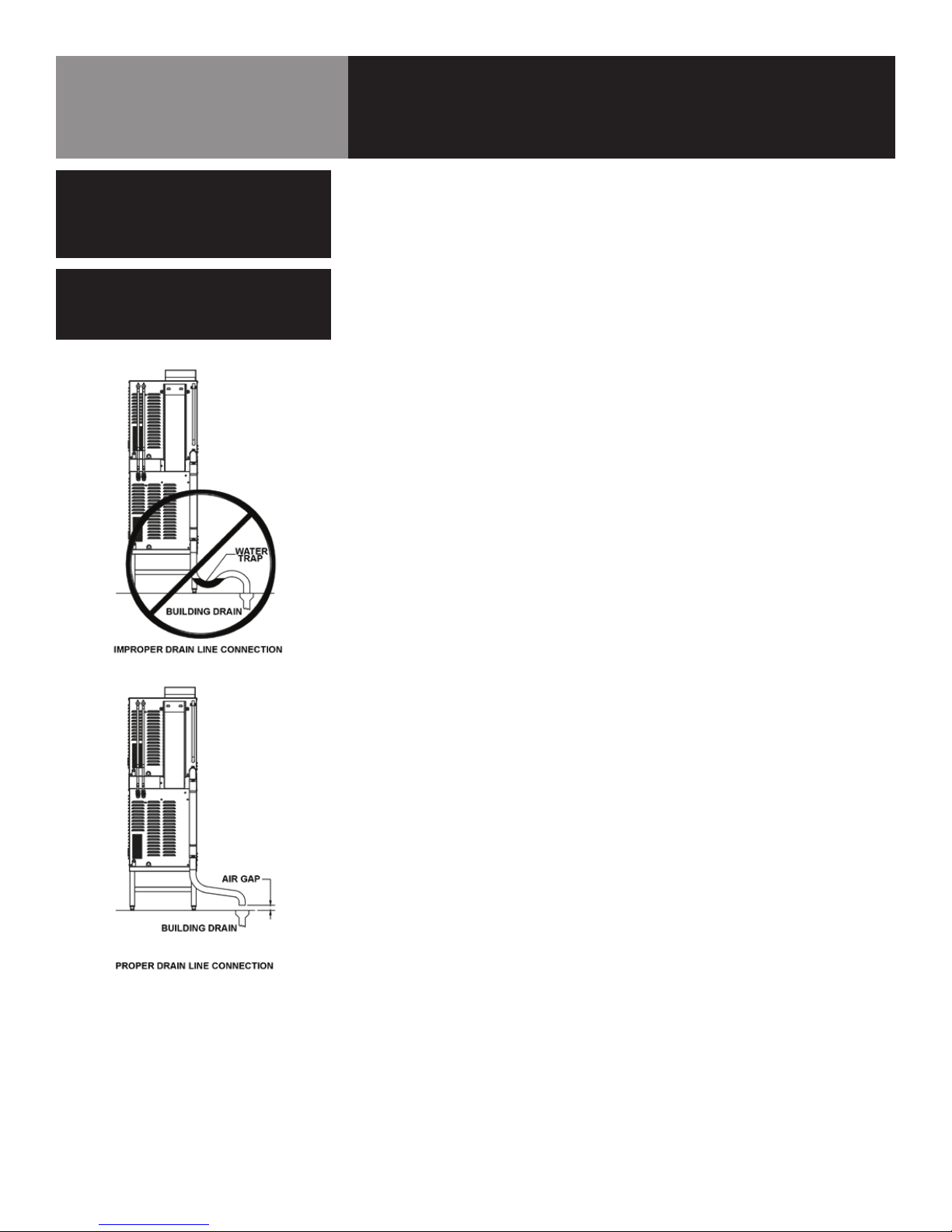
WARNING: DO NOT CONNECT THE DRAIN DIRECTLY TO A BUILDING DRAIN.
WARNING: BLOCKING THE DRAIN IS HAZARDOUS.
IMPORTANT: IMPROPER DRAIN CONNECTION WILL VOID WARRANTY.
IMPORTANT: DO NOT ALLOW ANY WATER TRAPS IN THE LINE. A TRAP CAN CAUSE PRESSURE TO BUILD UP
INSIDE THE CAVITY DURING STEAMING, WHICH WILL MAKE THE DOOR GASKET LEAK.
WARNING: WHEN YOU OPEN THE DOOR, STAY AWAY FROM STEAM COMING OUT OF THE UNIT. STEAM CAN
CAUSE BURNS.
WARNING: BEFORE CLEANING THE OUTSIDE OF THE STEAMER, DISCONNECT THE ELECTRIC POWER SUPPLY.
KEEP WATER AND CLEANING SOLUTIONS OUT OF CONTROLS AND ELECTRICAL COMPONENTS.
NEVER HOSE OR STEAM CLEAN ANY PART OF THE UNIT.
WARNING: ALLOW COOKING CHAMBER TO COOL BEFORE CLEANING.
WARNING: CAREFULLY READ THE WARNINGS AND FOLLOW THE DIRECTIONS ON THE LABEL OF EACH
CLEANING AGENT. USE SAFETY GLASSES AND RUBBER GLOVES AS RECOMMENDED BY DELIMING
AGENT MANUFACTURER.
WARNING: DO NOT MIX DE-LIMING AGENTS (ACID) AND DE-GREASERS (ALKALI).
WARNING: DO NOT PUT HANDS OR TOOLS INTO THE COOKING CHAMBER UNTIL THE FAN HAS STOPPED
TURNING.
WARNING: DO NOT OPERATE THE UNIT UNLESS THE REMOVABLE RIGHT SIDE PANEL HAS BEEN RETURNED
TO ITS PROPER LOCATION.
NOTICE: DO NOT USE A CLEANING OR DE-LIMING AGENT THAT CONTAINS ANY SULFAMIC ACID, OR ANY
CHLORIDE, INCLUDING HYDROCHLORIC ACID. IF THE CHLORIDE CONTENT OF ANY PRODUCT IS
UNCLEAR, CONSULT THE MANUFACTURER. DO NOT USE A CLEANING OR DE-LIMING AGENT THAT
CONTAINS MORE THAN 30% PHOSPHORIC ACID.
2 OM-HY/5G
Page 3

IMPORTANT - READ FIRST - IMPORTANT
NOTICE: DO NOT USE ANY DE-GREASER THAT CONTAINS POTASSIUM HYDROXIDE OR SODIUM HYDROXIDE
OR THAT IS ALKALINE.
WARNING: USE OF ANY REPLACEMENT PARTS OTHER THAN THOSE SUPPLIED BY GROEN OR THEIR
AUTHORIZED DISTRIBUTOR VOIDS ALL WARRANTIES AND CAN RESULT IN BODILY INJURY TO THE
OPERATOR AND DAMAGE THE EQUIPMENT. SERVICE BY OTHER THAN FACTORY-AUTHORIZED
PERSONNEL WILL VOID ALL WARRANTIES.
WARNING: HIGH VOLTAGE EXISTS INSIDE CONTROL COMPARTMENTS. DISCONNECT FROM BRANCH CIRCUIT
BEFORE SERVICING. FAILURE TO DO SO CAN RESULT IN SERIOUS INJURY OR DEATH.
OM-HY/5G 3
Page 4

Table of Contents
Important Operator Warnings ....................................................page 2-3
References.................................................................................... page 4
Equipment Description.................................................................. page 5
Water Quality and Treatment .......................................................... page 6
Inspection and Unpacking ............................................................ page 7
Installation .................................................................................. page 8-9
Initial Start-Up............................................................................... page 10
Operation ................................................................................ page 11-12
Cleaning.................................................................................. page 13-14
Maintenance................................................................................. page 15
Troubleshooting............................................................................ page 16
Electrical Schematic .................................................................. page 40
Service Log ................................................................................. page 41
References
UNDERWRITERS LABORATORIES, INC.
333 Pngsten Road
Northbrook, IL 60062
NSF INTERNATIONAL
P.O Box 130140
789 N. Dixboro Road
Ann Arbor, MI 48105, USA
NFPA – NATIONAL FIRE PROTECTION ASSOCIATION
1 Batterymarch Park
Quincy, MA 02169
ANSI – AMERICAN NATIONAL STANDARDS INSTITUTE
1899 L Street, NW, 11th Floor
Washington, DC 20036
CSA INTERNATIONAL
178 Rexdale Blvd.
Toronto, ON
Canada M9W1R3
4 OM-HY/5G
ICC – INTERNATIONAL CODE COUNCIL
500 New Jersey Avenue, NW
6th Floor, Washington, DC 20001
Page 5
Equipment Description
WARNING
BEFORE REMOVING ANY PARTITION OR
PANEL, TURN OFF THE ELECTRICAL POWER
AND LET THE FAN STOP ROTATING.
BEFORE WORKING ON ANY ELECTRICAL
COMPONENT, DISCONNECT THE POWER
SOURCE FROM THE UNIT.
WARNING
THE UNIT MUST BE INSTALLED BY
PERSONNEL WHO ARE QUALIFIED TO
WORK WITH ELECTRICITY AND PLUMBING.
IMPROPER INSTALLATION CAN CAUSE
INJURY TO PERSONNEL AND/OR DAMAGE TO
THE EQUIPMENT. THE UNIT MUST BE
INSTALLED IN ACCORDANCE WITH
APPLICABLE CODES.
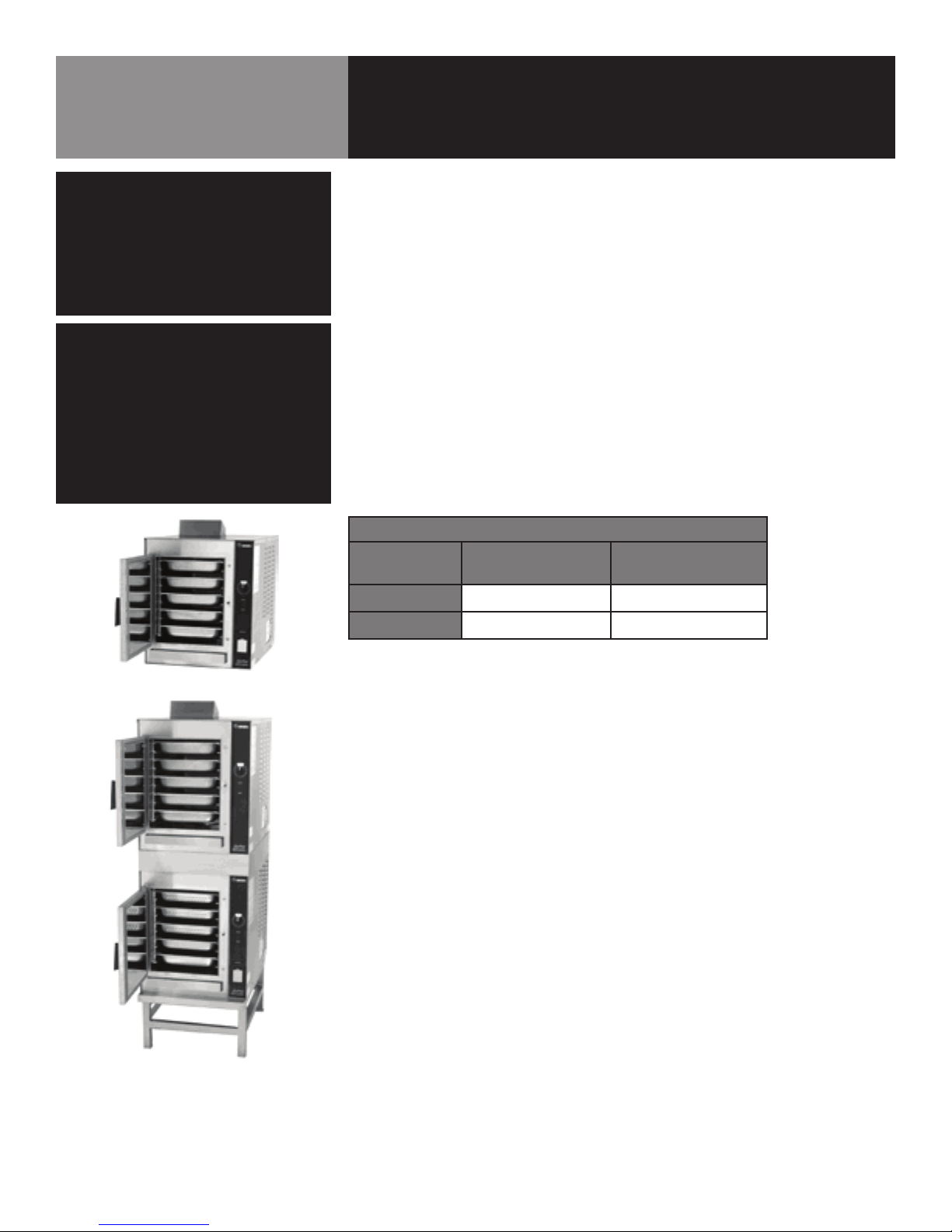
Your Groen HY-5G or (2)HY-5G HyPerSteam Convection Steamer is designed to give
years of service. It has a stainless steel cavity (cooking chamber) which is served by
an independent atmospheric steam generator which is gas-heated. A powerful blower
circulates the steam in the cavity to increase heating efficiency.
Each cavity holds up to five steam table pans (12” x 20” x 2½” deep). An 18 gauge
stainless steel case encloses the cavity, the steam generator and the control
compartment that houses electrical components. Door hinges are reversible (the door
may be set to open from the left or right). Operating Controls are on the front panel.
The HY-5G steamer is equipped with fully electronic controls and a button-activated,
pre-programmed CLEAN cycle. These units are readily identified by their unique
control panels. The On-Off switch is operated by touch pad controls, and the
distinctive symbol for steam is integrated into the panel.
The drain system on all models includes a spray condenser, which helps keep steam
from escaping from the chamber and cools drain water.
BURNER FIRING RATES
STEAMER
HY-5G 62,000 62,000
(2)HY-5G 124,000 124,000
NATURAL GAS
at 3.2” W.C.
LP GAS
at 10.5” W.C.
The HY-5G steamer holds five standard
12” x 20” x 2½” steamer pans. The (2)HY-5G
holds up to five pans per cavity.
OM-HY/5G 5
Page 6
Treated
Water
Water Quality & Treatment
It is essential to supply the steam generator with water that will not form scale or cause
corrosion. Even though the steam generator is engineered to minimize scale formation
and the effects of corrosion, their development depends on the quality of your water and
the number of hours per day you operate the equipment.
Most water supplies are full of minerals and chemicals which are not suitable for use in
a steam generator.
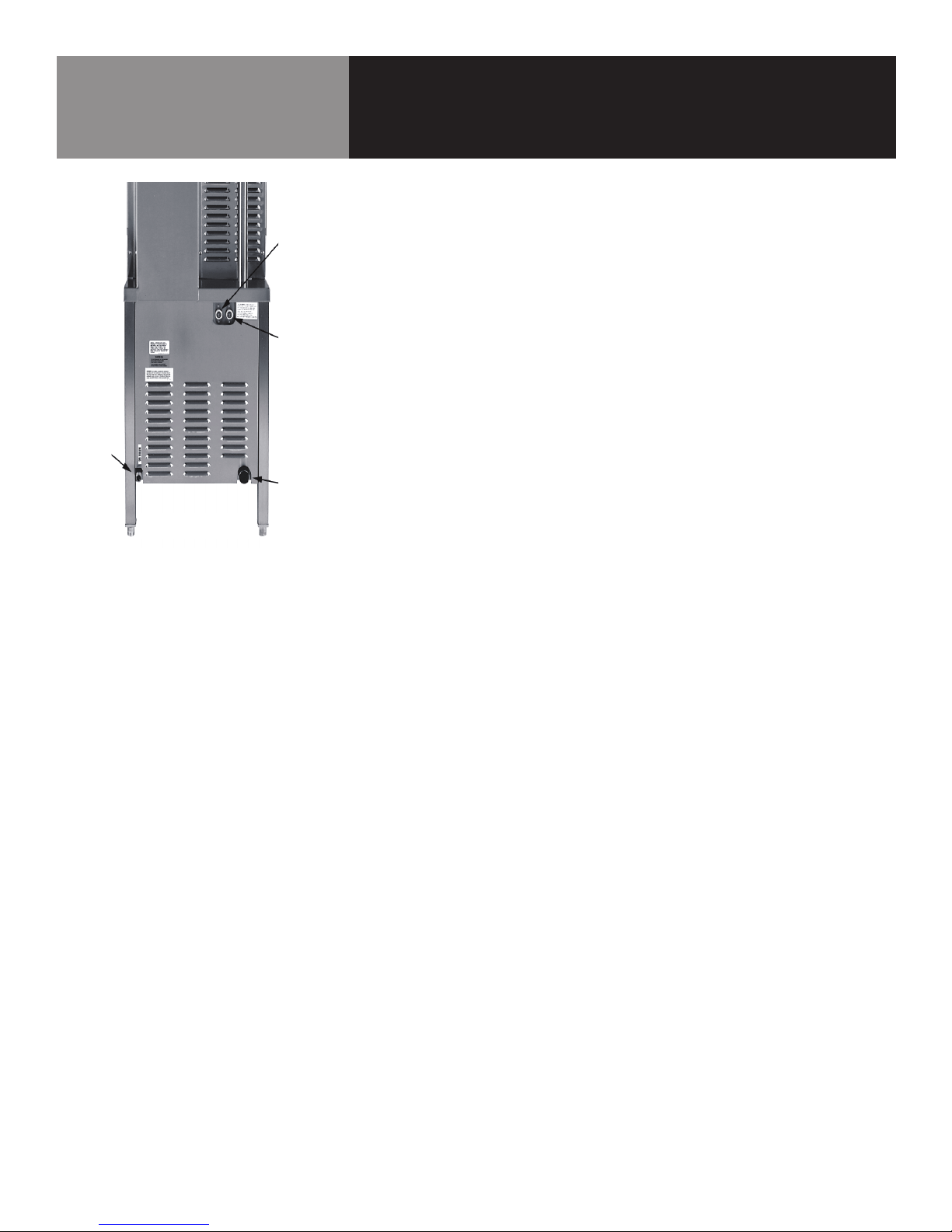
Gas
Connection
REAR VIEW
Untreated
Water
Drain
Water quality varies from state to state and city to city. It is necessary that you know
and understand the quality of the water you are using. Your water utility can tell you
about the minerals and chemicals in your water. The water going to the steam generator
should be within these guidelines
Water Pressure 30-60 psi
PH 7 to 9
Hardness less than 60 ppm
TDS 30 to 60 ppm
Chlorine and Chloramine less than 0.1 ppm
Total Chloride less than 30 ppm
Silica less than 12 ppm
Undissolved Solids less than 5 microns
1. Do not rely on unproven water treatments which are sold for scale prevention or
scale removal. They don’t always work. The best way to prevent scale is to supply
the purest possible water (30 - 60 ppm TDS).
2. If your water contains scale-forming minerals, as most water does, use a wellmaintained water softener. Whether an exchangeable softener cartridge or a
regenerating system is chosen, a regular exchange schedule is essential.
3. Installing a water meter between the softener and the steamer will provide an
accurate gauge of water use, and will help determine when to exchange cartridges
or regenerate the softener. Using a water softener will provide longer generator life,
higher steam capacity, and reduce maintenance requirements.
6 OM-HY/5G
4. If you notice a slowdown in steam production, have the unit checked for scale
build-up. Heavy scale reduces the unit’s ability to boil water and can even cause
heating elements in the steam generator to overheat and burn out
Page 7

Inspection & Unpacking
CAUTION
SHIPPING STRAPS ARE UNDER TENSION
AND CAN SNAP BACK WHEN CUT.
CAUTION
THE HY-5G WEIGHS 203 POUNDS (92 KG).
THE THE (2)HY-5G WEIGHS 460 POUNDS (207
KG). YOU SHOULD GET HELP AS NEEDED TO
LIFT THIS WEIGHT SAFELY.
The Steamer is delivered completely assembled in a heavy crate attached to a skid. On
receipt, inspect carefully for exterior damage.
Carefully detach the crating from the skid and carefully cut any straps securing the unit
to the skid. Be careful to avoid personal injury or equipment damage from staples in the
crating material and the skid.
Write down the model number, serial number and installation date. Keep this information
for reference. Space for these entries is provided at the top of the Service Log in the
back of this manual.
When starting installation, check packing materials to make sure loose parts such as the
condensate drip tray are not discarded with this material.
OM-HY/5G 7
Page 8
Installation
WARNING
THE UNIT MUST BE INSTALLED BY
PERSONNEL WHO ARE QUALIFIED TO WORK
WITH GAS, ELECTRICITY AND PLUMBING.
IMPROPER INSTALLATION CAN CAUSE
INJURY TO PERSONNEL AND/OR DAMAGE
TO THE EQUIPMENT. THE UNIT MUST BE
INSTALLED IN ACCORDANCE WITH
APPLICABLE CODES. THE UNIT MUST BE
INSTALLED BY A LICENSED PLUMBER OR
GAS FITTER WHEN INSTALLED WITHIN THE
COMMONWEALTH OF MASSACHUSETTS.
CAUTION
DO NOT INSTALL THE UNIT WITH THE RIGHT
OR LEFT SIDE VENTS BLOCKED OR WITHIN
12 INCHES OF A HEAT SOURCE (SUCH
AS A BRAISING PAN, DEEP FAT FRYER,
CHARBROILER OR KETTLE). TO AVOID DRAIN
PROBLEMS, LEVEL THE UNIT FRONT TO
BACK, OR PITCH IT SLIGHTLY TO THE REAR.
The HY-5G steamer is suitable for installation on or near both combustible and
noncombustible surfaces. Minimum installation clearances are:
Right Side 2 inches
Left Side 2 inches
Rear 6 inches
However, for easy service at least 12 inches clearance is required for the right side of
the unit, and it may not be installed within 12 inches of a heat source, as stated in the
Caution above.
The unit must be installed in a well-ventilated room with an adequate air supply. The
steamer must be installed beneath a ventilation hood, since gas combustion products
exit the appliance.
Any item which might obstruct or restrict the flow of air for combustion and ventilation
must be removed. Do not obstruct the flue cover or any front, side, rear, or top vents
after installation.
The area directly around the appliance must be cleared of all combustible material.
The installation must conform with local codes or, in the absence of local codes, with
the National Fuel Gas Code, ANSI Z223.1, latest edition, including the following:
The unit and its individual shutoff valve must be disconnected from the gas supply
system during any pressure testing of that system at test pressures in excess of 1/2
PSI (3.45 kPa). It must be isolated from the gas supply piping system by closing its
individual manual shutoff valve during any pressure testing of the gas supply piping
system at test pressures equal to or less than 1/2 PSI (3.45 kPa).
1. Electrical Supply Connection
Provide 115 VAC, 60 HZ, 1 PH, 15 AMP service. Bring conduit in through open
frame on the under-side of cabinet. Local codes and/or the National Electrical
Code should be observed in accordance with ANSI/NFPA 70-1987 (or latest
edition). AN ELECTRICAL GROUND IS REQUIRED. The electrical schematic is
located in the service compartment and in this manual. Maximum load is 2
AMPs. In Canada, provide electrical service in accordance with the Canadian
Electrical Code, CSA C22.1 Part 1 and/or local codes.
2. Gas Supply Connection
Connection to the gas supply can be completed with 1/2” NPT pipe or approved
equivalent. Although the immediate connection to the appliance is “ NPT, gas
supply piping must be large enough to provide 62,000 BTU/hr. Supply pressure
must be at least 4.5” W.C. (maximum 14” W.C.) for natural gas or 12” W.C.
(maximum 14” W.C.) for LP gas. In Canada, the installation must conform to the
Canadian Gas Code, CAN 1-B149, Installation Codes for Gas Burning Appliances
and Equipment and/or local codes. After the unit has been connected to the gas
supply, all gas joints must be checked for leaks. No flame should be used when
checking for leaks. A thick soap solution or other suitable leak detector should be
used. For a unit on casters, complete connection to the gas supply with connectors
that comply with the standard for connectors for moveable gas appliances, ANSI
Z21.69 — latest edition. Restrain movement of the unit by attaching a cable or
chain to the eyelet (provided at the back of the frame) and anchoring the cable or
chain to the wall or floor. Make the length and location of the cable such that the
unit cannot pull on the gas connection while the cable is connected.
8 OM-HY/5G
Page 9
Installation
WARNING
DO NOT CONNECT THE DRAIN DIRECTLY
TO A BUILDING DRAIN. BLOCKING THE
DRAIN IS HAZARDOUS.
CAUTION
DO NOT USE PLASTIC PIPE. DRAIN MUST BE
RATED FOR VERY HOT WATER.
3. Water Connection
Install a check valve to prevent back flow in the incoming cold water line, as
required by local plumbing codes. Water pressure in the line should be between
30 and 60 PSIG and must deliver a flow rate of 1.5 to 3.0 gallons per minute. If
pressure is above 60 PSIG, a pressure regulator will be needed. ¾ inch female
NH connectors (garden hose type) are used to attach the water supply to the
inlet valves. One connector is for the steam generator (treated), the other is for
the spray condenser (untreated). Minimum inside diameter of the water feed
line is ½ inch. Use a washer in the hose connection. Do not allow the connection
to leak, no matter how slowly. Do not over tighten hose connections. Treated
(softened) water goes to the right (seen from the rear of the unit), and untreated
water to the left. Connections for both are made as shown on Page 5. Though not
recommended, an adapter to use a single water intake is available, P/N 138473.
4. Drain Connection
Level the steamer front to back, or pitch it slightly to the rear (maximum ¼
inch) by adjusting the optional legs or bullet feet on optional stand. A 2 inch ID
hose may be attached to the drain pipe (supplied). There must be a free air gap
between the end of the hose and the building drain. The free air gap should be
as close as possible to the unit drain. There must also be no other elbows or
other restrictions between the unit drain and the free air gap. Install the drain
line with a constant downward pitch. IMPORTANT: Do not allow water traps in the
line. A trap can cause pressure build-up in the cavity, which may cause the door
gasket to leak.
Proper Drain Line Connection - Drain Line must
have a constant downward pitch of at least 1/4”
per foot. (2)HY-5G shown.
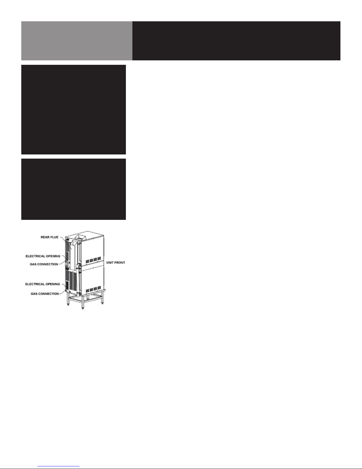
5. Factory Stacked Units
This section is applicable only if you are installing factory-stacked units. If you
plan to stack steamers yourself, whether purchasing a new one for stacking or a
kit to stack two units you already own, you will require OM-HY-5G(S), RETROFIT
SUPPLEMENT (Part Number 121087). Installing stacked steamers is similar to
installing a single unit. The steamers are stacked and assembled at the factory
and delivered with the water connections and drain hoses required for a single
point connection.
A. Water Connection: The same water supply connection is used for both
units. At the water inlet valves, ¾ inch female NH connectors (garden
hose type) are used for the water supplies. There are two connections to
be made. Treated water (softened) is connected to the right valve fitting
(looking from the rear of the unit) and untreated water to the left fitting.
B. Electrical Supply Connection: Separate, individual electrical connections
will be required for each steamer in the stack. Each Steamer must have its
own branch circuit protection.
C. Gas Connection: Separate gas connections are required for each steamer in the
stack. Gas supply must be adequate under all conditions as listed on page 8.
D. Drain Connection: Steamers must be leveled front to back, or pitched to
the rear (maximum ¼ inch) by adjusting the bullet feet on the stand. A 2
inch ID hose may be attached to the unit drain. It must be rated for very hot
water. Ensure that there is a free air gap between the end of the unit drain
and the building drain. This gap should be as close as possible to the unit
drain. Do not allow elbows or restrictions between the unit and the free air
gap. Install the line with a constant downward pitch.
OM-HY/5G 9
Page 10

Initial Start-Up
WARNING
WHEN YOU OPEN THE DOOR, STAY AWAY
FROM STEAM COMING OUT OF THE UNIT.
THE STEAM CAN CAUSE BURNS.
Automatic Operation of Pilot
Once the pilot burner is lit, it essentially
functions as a standing pilot. In this state,
if the pilot is accidentally extinguished (by
a very strong gust of wind for example), it
will re-ignite automatically. The unit will
completely shut down. Operator must turn
off and then back on to reset. Then the unit
will come back on and resume operation in
the mode and with the (running) timer value
existing just prior to shutdown. The pilot
switch may be turned off during “off hours”
to conserve energy.
After the unit has been running, if the pilot
burner ever fails to re-ignite automatically
within 90 seconds, wait 5 minutes before
you attempt to reactivate it. In the unlikely
event that ignition problems persist, contact
your authorized Groen Service Agency.
NOTE: For operation at high altitudes (2000
feet and above) please consult the Groen
Food Service Engineering Department.
After the HY-5G Steamer has been installed, test it to ensure that the unit is operating
correctly.
Remove all literature and packing materials from the interior and exterior of the unit.
1.
2. Make sure the water supply line is open.
3. Make sure that the gas supply line is open and that the manual knob on the
main gas valve is turned to the “on” position. This valve is located behind the
access panel on the right side of the unit.
4. Turn on electrical service to the unit. The HY-5G will not operate without
electrical power. Do not attempt to operate the unit during a power failure.
5. The steamer will not operate until the pilot burner has been ignited. To light the
pilot burner, activate the pilot switch located next to the main gas valve. When
the pilot ignition sequence has been successfully completed, a green light - on
the pilot switch (old models) - and on the electrical panel (new models) will glow.
6. The “trial for ignition” period is roughly 90 seconds. If the pilot burner does not
light within about 90 seconds after the switch is activated, the ignition system
automatically stops gas flow to the pilot burner and stops the ignition trial. If
this happens, turn off the pilot switch and repeat the trial for ignition. During
the initial start-up, the pilot may require several trials for ignition until all the air
is bled from the gas piping. Subsequent start-ups should require only about 5
seconds to achieve pilot ignition.
NOTE: See Automatic Operation of Pilot at left.
7. Once the pilot burner flame has been established (the green light on the pilot
switch (old models) or electrical panel (new models) is on), press the “ON” switch
for the desired steamer cavity. The steam generator will fill with water.
NOTE: The door MUST be closed for the main burner to work.
10 OM-HY/5G
8. When the steam generator has filled with water, the burners will ignite
automatically. Within approximately 8-10 minutes the READY light will come on,
indicating that the water has reached its standby temperature. When the READY
light is displayed, you may take any one of the following steps:
a. Set the timer to the desired time for timed steaming.
b. Turn the timer knob to the manual ON position for continuous steam.
c. Let the unit stay at standby temperature.
9. To shut down the unit, press the ON switch into the off position. The steam
generator will then drain. You may also switch off the pilot switch to conserve
energy.
10. If the HY-5G Steamer behaves as described, the unit is functioning correctly and
ready for use.
Page 11
Operation
WARNING
ALL POTENTIAL USERS OF THE EQUIPMENT
SHOULD BE TRAINED IN SAFE AND CORRECT
OPERATING PROCEDURES.
NO ATTEMPT SHOULD BE MADE TO
OPERATE THIS EQUIPMENT DURING
A POWER FAILURE.
WARNING
WHEN YOU OPEN THE DOOR, STAY AWAY
FROM THE STEAM COMING OUT OF THE
UNIT. THE STEAM CAN CAUSE BURNS.
NOTE: Before the steamer can be operated as described in this section, the pilot
burner flame must be established. For details see the Initial Start-Up section and the
Automatic Operation of Pilot on previous page.
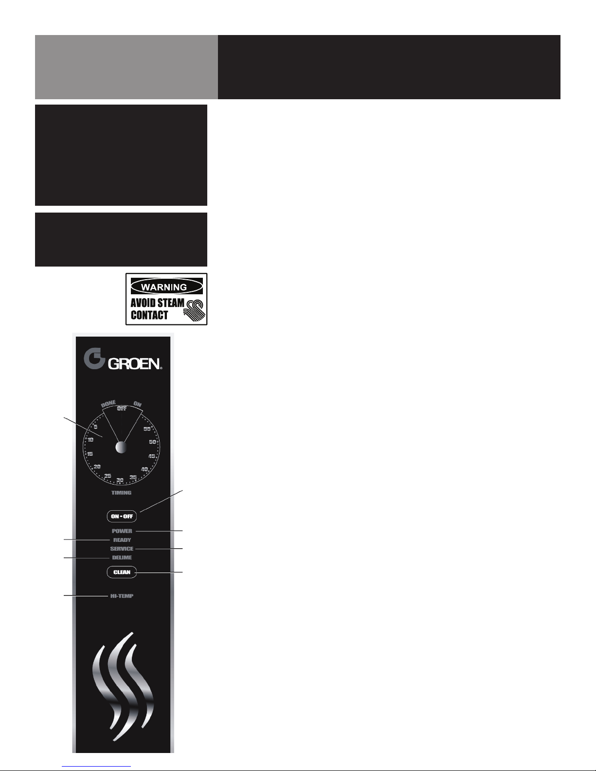
A. Controls
Operator controls are on the front right of the unit. The control panel has the
following touch pads and indicator lights:
• The ON/OFF touch pad gets the HyPerSteam ready for use, or shuts it off.
• The READY indicator light shows that the steam generator is at standby
temperature and the cavity is hot enough to begin steaming.
• The DELIME indicator light is lit when the unit is operating in the cleaning
mode.
• The SERVICE indicator light shows when the water level probes have stopped
working, and need to be cleaned (normally an indication of lime deposits).
When one probe is not working, the DELIME light flashes briefly every few
seconds. If both probes fail the SERVICE light will come on continuously and
the beeper will sound.
• The HI TEMP indicator light comes on when the steam generator is too hot.
Steamer
Timer
Ready
Indicator
Light
Delime
Indicator
Light
Hi Temp
Indicator
Light
Power
ON/OFF
Button
Power
Indicator
Light
Service
Indicator
Light
Clean
Button
The unit will automatically shut off, and cannot be turned on again until the
steam generator cools and the HI TEMP indicator light goes out.
• The TIMING indicator light stays on when the timer is running.
• The CLEAN touch pad is used to start the automatic 50 minute cleaning cycle.
The timer is used in three ways:
1. In the OFF position the steam generator stays at a low boil or “holding”
temperature.
2. When a cook time is set, the unit steams until the timer runs down to OFF.
Steaming stops, the DONE light (a red light on older models) comes on and
a beeper sounds.
3. With the timer turned to the ON position, the unit steams continuously. The
green light stays lit. The steamer will not time down.
OM-HY/5G 11
Page 12

Steamer
Timer
Ready
Indicator
Light
Delime
Indicator
Light
Hi Temp
Indicator
Light
Power
ON/OFF
Button
Power
Indicator
Light
Service
Indicator
Light
Clean
Button
Operation
B. Operating Procedure
1. Press the ON switch/pad for the steamer. The steam generator will fill, and
heat until the READY light comes on. (Aprox. 10 minutes.)
2. Load food into pans in uniform layers. Pans should be filled to about the
same levels, and should be even on top.
3. Open the door and slide the pans onto the supports. If you will only be
steaming one pan, put it in the middle position.
4. Close the door. With the READY indicator lit, take one of the following steps:
• If you want to steam the food for a certain length of time, set the timer
for that period. The timer will automatically run the steamer for the
set time and then turn it off. A red light will come on and a beeper will
sound. Steam production stops.
• If you want to steam continuously, turn the timer to the manual ON
position. A green light will come on. The unit will continue steaming until
you stop it by turning the timer to OFF. When steaming continuously YOU
MUST CONTROL STEAMING TIME.
5. Open the door. Remove the pans from the steamer, using hot pads or oven
mitts to protect your hands from the hot pans.
6. To shut down the unit, press the ON/OFF touch pad. The steam generator
will automatically drain.
12 OM-HY/5G
Page 13

Cleaning
WARNING
DISCONNECT THE POWER SUPPLY BEFORE
CLEANING THE OUTSIDE OF THE STEAMER.
KEEP WATER AND CLEANING SOLUTIONS
OUT OF CONTROLS AND ELECTRICAL
COMPONENTS. NEVER HOSE OR STEAM
CLEAN ANY PART OF THE UNIT.
DON’T MIX DE-LIMING AGENTS (ACID) WITH DE-
GREASERS (ALKALI) ANYWHERE IN THE UNIT.
AVOID CONTACT WITH ANY CLEANERS,
DE-LIMING AGENT OR DE-GREASER AS
RECOMMENDED BY THE SUPPLIER. MANY
ARE HARMFUL. READ THE WARNINGS AND
FOLLOW THE DIRECTIONS!
EVEN WHEN THE UNIT HAS BEEN SHUT OFF,
DON’T PUT HANDS OR TOOLS INTO THE
COOKING CHAMBER UNTIL THE FAN HAS
STOPPED TURNING.
DON’T OPERATE THE UNIT UNLESS THE TWO
REMOVABLE INTERIOR PARTITIONS HAVE BEEN
PUT BACK IN THEIR PROPER LOCATIONS.
DON’T USE ANY CLEANING OR DELIMING
AGENT THAT CONTAINS ANY SULFAMIC
AGENT OR ANY CHLORIDE, INCLUDING
HYDROCHLORIC ACID (HCl). TO CHECK FOR
CHLORIDE CONTENT SEE ANY MATERIAL
SAFETY DATA SHEETS PROVIDED BY THE
CLEANING AGENT MANUFACTURER.
IMPORTANT
DO NOT USE ANY METAL MATERIAL (SUCH
AS METAL SPONGES) OR METAL IMPLEMENT
(SUCH AS A SPOON, SCRAPER OR WIRE
BRUSH) THAT MIGHT SCRATCH THE SURFACE.
SCRATCHES MAKE THE SURFACE HARD TO
CLEAN AND PROVIDE PLACES FOR BACTERIA
TO GROW. DO NOT USE STEEL WOOL, WHICH
MAY LEAVE PARTICLES IMBEDDED IN THE
SURFACE WHICH COULD EVENTUALLY CAUSE
CORROSION AND PITTING.
To keep your HY-5G Steamer in proper working order, use the following procedure to
clean the unit. This regular cleaning will reduce the effort required to clean the steam
generators and cavities.
A. Suggested Tools
a. Mild detergent
b. Stainless steel exterior cleaner such as Zepper®
c. Steam generator de-liming agent, such as Groen Delimer Descaler. A liquid
de-liming agent will be easier to use than crystals or powders. See the
warning about chlorides, below
d. De-greaser
e. Cloth or sponge
f. Plastic wool or a brush with soft bristles
g. Spray bottle
h. Measuring cup
i. Nylon pad
j. Towels
k. Plastic disposable gloves
l. Funnel
B. Procedure
1. Outside
a. Prepare a warm solution of the mild detergent as instructed by the
supplier. Wet a cloth with this solution and wring it out. Use the moist
cloth to clean the outside of the unit. Do not allow freely running liquid
to touch the controls, the control panel, any electrical part, or any
open louver.
b. To remove material which may be stuck to the unit, use plastic wool,
a fiber brush, or a plastic or rubber scraper with a detergent solution.
c. Stainless steel surfaces may be polished with a recognized stainless
steel cleaner such as Zepper®.
2. Steam Generator and Cooking Chamber
Regular deliming, depending on your steamer usage and local water
quality, must be done to enhance performance and prolong the life of your
HyPerSteam™ convection steamer. Steamer must be turned off after every
use to prevent lime scale buildup - do not run steamer continuously.
ALWAYS USE HOT PADS OR MITTS WHEN HANDLING HOT STEAMER PAN-
ELS OR RACKS.
RECOMMENDED TOOLS & CLEANERS:
• Groen Delimer/Descaler (Part Number 114800). Do NOT use any
product containing chlorides or sulfamic acid, including hydrochloric
acid.
• Nylon scrub pad, cloth and/or sponge
OM-HY/5G 13
Page 14

Cleaning
CAUTION
NEVER LEAVE A CHLORINE SANITIZER IN
CONTACT WITH STAINLESS STEEL
SURFACES FOR LONGER THAN 30
MINUTES. LONGER CONTACT CAN
CAUSE CORROSION.
Deliming
Port
DELIMING STEPS HY-5G (Use Touch Pad):
STEP 1
Press ON/OFF to turn steamer off. Open door.
STEP 2
Let cavity cool for 5 minutes or longer. While cool, wipe out cavity. Close
door.
STEP 3
Press and hold CLEAN while also turning steamer on by pressing ON/OFF,
until only DELIME and POWER lights remain on (all lights will turn on, then
off, except DELIME and POWER).
STEP 4
After 5 minutes, beeper will beep rapidly, signaling you to add Groen Delimer/ Descaler. Door(s) must remain closed for entire delime cycle.
STEP 5
Pour 1 pint (2 cups) of delimer PER CAVITY into upper and /or lower deliming port(s) and then close port(s). Press CLEAN. Double-stacked unit cavities may be delimed together or seperately
STEP 6
Delime cycle will start, taking about 30 minutes. When delime cycle is complete, DELIME light will appear, DONE light will flash and beeper will beep.
STEP 7
Press ON/OFF to turn steamer off. Let cavity cool for 5 minutes or longer.
Open door, wipe out inside of cavity and wipe door gasket. Close door.
STEP 8
To use steamer, press ON/OFF. When READY light appears, steamer is ready
to use.
NOTES:
• If DELIME light flashes rapidly (5 times per second), press DELIME to
restart delime cycle.
• If power outage occurs during deliming, delime cycle must be restarted. Press DELIME.
• For best performance, do not interrupt delime cycle. If delime cycle
must be stopped, press ON/OFF to turn on. Set timer for 5 minutes.
After beeper beeps, press ON/OFF to turn off. Let cavity cool for 5
minutes or longer, carefully open door(s) and wipe out cavity completely.
14 OM-HY/5G
Page 15

Maintenance
NOTE
THE UNIT CONTAINS NO FUSES THAT SHOULD
BE REPLACED BY THE OPERATOR.
The HY-5G Steamer is designed for minimum maintenance, and no user adjustments
should be necessary. Certain parts may need replacement after prolonged use. If
there is a need for service, only Groen personnel or authorized Groen representatives
should perform the work. Always supply water with a low mineral count that meets the
standards outlined in the Water Conditioning section of this manual.
If steam or condensate is seen leaking from around the door, take the following steps:
1. Check the door gasket. Replace if it is cracked or split.
2. Inspect the cooking chamber drain to be sure it is not blocked.
3. Adjust the latch pin to allow for changes that might occur as the gasket ages.
a. Loosen the lock nut at the base of the latch pin. Turn the latch pin ¼ turn
clockwise, and re-tighten the lock nut.
b. After adjustment, run the unit to test for further steam leakage.
c. If there is still leakage, repeat the adjustment.
d. Continue adjusting the pin clockwise until the door fits tightly enough to
prevent leakage.
OM-HY/5G 15
Page 16

Troubleshooting
This Groen Steamer is designed to operate smoothly and efficiently if properly maintained. However, the following is a list of
checks to make in the event of a problem. Wiring diagrams are furnished inside the service panel. If an item on the check list
is marked with (X), it means that the work should be done by a factory-authorized service representative.
SYMPTOM WHO WHAT TO CHECK
Pilot will not light. User a. Are electrical connections made with a ground?
b. Is gas supply connection made?
c. Is pilot ignition switch on?
d. Is gas valve turned on?
e. Are building fuses or circuit breakers all right?
f. Are there drafts which could blow out the pilot?
Authorized
Service Rep Only
Steam generator does not ll
with water.
No steam. User a. Is the ON switch depressed?
Service light comes on after
four minutes.
Excessive steam escaping
from rear of unit.
User a. Is the ON switch depressed?
User a. Is the water supply connected?
User a. Is the water spray hose kinked or obstructed?
Authorized
Service Rep Only
g. Is spark ignition cable connected to module? X
b. Is the water supply connected?
c. Is the water turned on?
d. Check for low water pressure (less than 30 PSI or 210 kPa).
e. Is the screen at the water connection clogged?
f. Has the steam generator been delimed?
b. Is the water supply connected?
c. Is the water turned on?
d. Are steamer doors open?
e. Is the steam generator limed up?
b. Is the water turned on?
c. Has the unit been delimed? (Refer to Cleaning Section)
b. Is the water spray solenoid connected? X
c. Is the drain properly vented? X
16 OM-HY/5G
Page 17

Key Description Part #
1 STEAMER CONTROL BOARD
ASSEMBLY
2 LIGHT & TIMER PC BOARD
ASM
5 STANDOFF, 6-32, 3/4" LONG 119826
6 STANDOFF, 6-32, 1-1/4"
LONG
7 COVER, PANEL CONTROL 143255
8 NUT, LOCK, NYLON INSERT,
6-32
- HARNESS, JUMPER, CONTROL BD TO RIBBON CONN
- HARNESS, TIMER MOTOR 123120
- JUMPER, VOLTAGE SELECT,
120VAC
- HARNESS, TRANSFORMER 2 119871
- HARNESS, READY SWITCH 119878
15 KNOB, TIMER 123100
16 TIMER, STEAMER, 24VAC,
60HZ
17 NUT, ROTARY SHAFT SEAL,
3/8-32
19 Sink Drain Fitting 099943
20 Upper Left Panel 123184
21 Top Panel 123182
22 Back Panel 125799
141082
137233
119827
119855
123122
123123
Z096826
101145
Parts List
Control & Timer Assembly
OM-HY/5G 17
Page 18

Key Description Part #
1 VALVE, WATER, SINGLE WAY 100934
2 VALVE, WATER, SINGLE INLET, DUAL
OUTLET
3 SCREW, TRS HD, 8-32, 3/8" LONG Z005764
4 HOSE, CLEAR PVC, 3/8" ID, WATER
FILL, 64" LONG
5 CLAMP, HOSE, DOUBLE WIRE, DW-9.5 127527
6 CLAMP, CONSTANT TENSION, CTB-19 126095
7 HOSE, CLEAR PVC, 3/8" ID, EDUCTOR,
46" LONG
8 HOSE, BLACK RUBBER, 3/8 ID, CON-
DENSATE, 42" LONG
9 HOSE, 1/2 I.D. X 24.0 LONG 138451
10 CLAMP, DOUBLE WIRE, DW-12 127662
11 REDUCER, WATER FLOW (.078 ID) Z088877
12 CLAMP, HOSE, SS, 1/4 MIN, 25/32
MAX
13 ASSEMBLY, ELECTRICAL, BOTTOM 138561
14 ASSEMBLY, ELECTRICAL, TOP 138551
15 ASSEMBLY, MAIN POWER BOX 138429
16 NUT, HEX KEPS, 10-32 Z071256
17 WASHER, FLAT, 10 Z010414
18 U BOLT, 1-1/8 ID, 1/4-20 THRD, FOR
3/4" PIPE
19 NUT, HEX SERRATED, 1/4-20 NT1101
- ASSEMBLY, GAS TRAIN 142109
21 WASHER, PLAIN, 1/4 Z005472
22 BRACKET, SWITCH 106451
23 SWITCH, ROCKER, SP-ST Z087951
24 SCREW, FLAT HEAD, PHILLIPS, 8-32,
3/8" LONG
25 CLAMP, CONSTANT TENSION, CTB-16 127522
- HARNESS, POWER 130397
- HARNESS, DRAIN 130398
- HARNESS, CONTROL HY-5G 141836
- CABLE, HI VOLTAGE, SPARK IGNITION 106495
- HARNESS, CONTROL BOARD 141084
32 SCREW, HEX WSHR HD, 10-32, 3/8"
LONG
Z071235
138467
138452
138468
Z093482
N87786
127178
Z069773
Parts List
Electrical & Gas Assembly
18 OM-HY/5G
Page 19

Parts List
Electrical & Gas Assembly
OM-HY/5G 19
Page 20

Key Description Part #
1 WELDMENT, BOTTOM
BRACKET
2 SCREW, HEX WSHR HD,
6-32, 3/8" LONG
3 RELAY, DPST, NO, 24VDC 138420
4 CAPACITOR, FOIL, 3 MFD Z096813
- LOCTITE, #242 Z073282
138455
Z069788
Parts List
Bottom Electrical Assembly
Key Description Part #
1 WELDMENT, TOP BRACKET 138453
2 TRANSFORMER, 75VA
120/24
3 RELAY, CUTOUT, 24V 119814
4 RELAY, 12 VDC 119813
5 TRANSFORMER,
115V/230V:24V, 30VA
6 SCREW, HEX WSHR HD,
6-32, 3/8" LONG
7 SCREW, HEX WSHR HD,
6-32, 1/4" LONG
8 IGNITION MODULE, GAS, 25V Z085153
9 CLAMP, 1/2 DIA LOOP, NYLON Z089343
10 WELDMENT, MOUNTING
SUPPORT
11 BRACKET, TRANSFORMER 148624
12 LOCTITE, #242 Z073282
121715
119815
Z069788
Z069777
138454
Parts List
Top Electrical Assembly
20 OM-HY/5G
Page 21

Key Description Part #
1 WELDMENT, MAIN POWER
BOX
2 TERMINAL BLOCK, 2-POLE Z003887
3 LUG, GROUND, #14 - #6
AWG
4 FUSE HOLDER, TYPE 3 AG Z077854
5 BUSHING, SNAP, 1/2 ID Z009884
6 BUSHING, SNAP, 11/16 ID Z012864
138456
129714
Parts List
Main Power Box Assembly
7 SCREW, RND HD, 6-32,
1-1/4" LONG
8 SCREW, PAN HD, 6-32. 3/8"
LONG
9 SCREW, HEX WSHR HD,
6-32, 3/8" LONG
10 FUSE, 3.0 AMP, TYPE 3 AG Z077853
11 LOCTITE, #242 Z073282
Z011236
Z009697
Z069788
OM-HY/5G 21
Page 22

Key Description Part #
1 VALVE, GAS Z098443
2 ASSEMBLY, PIPE BRACKET 171016
3 ELBOW, STREET, 90 DEG,
1/2 NPT
4 CONNECTOR, STRAIGHT, 1/8
NPT TO 1/4 TUBE
5 CONNECTOR, STRAIGHT, 3/8
NPT TO 1/2 TUBE
6 CONNECTOR, STRAIGHT, 1/2
NPT TO 1/2 TUBE
7 TUBING, FLEXIBLE, GAS, SS,
1/2 OD, 14" LONG
8 VALVE, GAS, MANUAL SHUT-
OFF, 1/2 NPT
- PIPE DOPE Z078938
- CAP, PROTECTOR, INTERNAL,
3/4 IPS
Z004185
Z075055
Z054494
171044
NT1561
Z098458
Z001252
Parts List
Gas Train Assembly
22 OM-HY/5G
Page 23

Key Description Part #
1 ASSEMBLY, STEAM GENERA-
TOR, HY-5G
2 NUT, HEX SERRATED, 1/4-20 NT1101
3 HOSE, CLEAR PVC, REIN-
FORCED, 3/4 ID, 7-3/8"
LONG
4 HOSE, CLEAR PVC, REIN-
FORCED, 3/4 ID, 4" LONG
BOILER DRAIN
5 HOSE, SANTOPRENE, 1-1/2
ID, STEAM, 10-1/2 LONG
6 TUBE, 45 DEG BEND, 1.50
OD, SS
7 HOSE, SANTOPRENE, 1-1/2
ID, STEAM, 8-1/4 LONG
8 CLAMP, HOSE, CONSTANT
TENSION, CTB-47
9 CLAMP, HOSE, CONSTANT
TENSION, CTB-27
10 TRAP, BOILER 106229
141820
138464
138465
138445
138412
138446
127526
138457
Parts List
Steam Generator & Plumbing Assembly
OM-HY/5G 23
Page 24

Key Description Part #
- ASSEMBLY, STEAM GENERATOR, SERVICE, HY-5G
1 WELDMENT, STEAM GEN-
ERATOR, HY-5G
2 INSULATION, STEAM GEN-
ERATOR, HY-5G
3 SENSOR, OVER TEMP Z096892
4 VALVE, PRESSURE RELIEF,
1/2 PSI, 3/8 NPT
5 GASKET, DRAIN 106232
6 PLATE, DRAIN 106226
7 NUT, HEX KEPS, 5/16-18 Z012941
8 ELBOW, 90 DEG, COMPRES-
SION, 3/8 NPT TO 1/2" TUBE
9 ELBOW, 90 DEG, COMPRES-
SION, 1/2 NPT TO 3/4" TUBE
10 PROBE, WATER LEVEL 141424
- PIPE DOPE Z078938
- TAPE, DUCT, 3" WIDE Z042359
14 SLEEVING, VARGLAS, 7/16 152010
138521S
141821
138588
140867
Z090737
138442
Parts List
Steam Generator Assembly
24 OM-HY/5G
Page 25

Key Description Part #
1 INSULATOR, MOTOR Z094135
2 MOTOR, BLOWER 146880
3 WHEEL, BLOWER Z096790
4 SEAL MOTOR Z096868
5 LUBRICANT, MOTOR SHAFT
SEAL
6 NUT, HEX SERRATED, 1/4-20 NT1101
7 WIREFORM NT1801
8 ASSEMBLY, BLOWER COVER,
HY-5
Z099948
162915
Parts List
Blower/Rack Assembly
OM-HY/5G 25
Page 26

Key Description Part #
1 BASE PAN ASSEMBLY 142128
2 CAVITY & DRAIN ASSEMBLY 138550
3 SCREW, HEX HEAD CAP, 1/4-
20, 1/2" LONG
4 NUT, HEX SERRATED, 1/4-20 NT1101
- LOCTITE, #242 -
Z005608
Parts List
Base & Cavity Assembly
26 OM-HY/5G
Page 27

Key Description Part #
1 WELDMENT, BASE PAN
HY-5G
2 DELIME EDUCTOR ASSEM-
BLY HY-5G
3 VALVE, CHECK, 3/8 HOSE
BARB
4 HOSE, REINFORCED PVC,
CLEAR, 3/8 ID, 1-3/4" LONG
5 CLAMP, HOSE, DOUBLE
WIRE, DW-9.5
6 BRACKET, DRAIN VALVE 138592
7 NUT, HEX KEPS, 10-32 Z071256
8 VALVE, SOLENOID, 1/2 NPT,
24 VAC
9 FITTING, STRAIGHT, 1/2 NPT
TO 3/4 HOSE
10 ELBOW, 90 DEG, 1/2 NPT TO
3/4 HOSE
11 FITTING, 1/4 NPT TO 3/8
HOSE BARB
12 STRAP, PIPE, 1-1/2" 141693
13 NUT, HEX SERRATED, 1/4-20 NT1101
- LOCTITE, #242 -
- PIPE DOPE -
138500
142131
138428
138448
127527
Z074594
138441
138442
Z069732
Parts List
Base Pan Assembly
OM-HY/5G 27
Page 28

Key Description Part #
1 INSULATION, LEFT AND
RIGHT
2 INSULATION TOP Z096846
3 WELDMENT, FRONT PANEL,
W/DELIME PORT
4 PANEL, FRONT, LEFT SIDE 125947
5 PIN, DOOR LATCH Z078914
6 NUT, HEX JAM, 5/16-18 Z003823
125929
138539
Parts List
Door & Front Panel Assembly
7 SCREW, TRUSS HEAD, 1/4-
20, 1/2" LONG
8 ASSEMBLY, DOOR, 5-PAN 125922
9 SCREW, HEX HD CAP, 1/4-20,
1/2" LONG
10 NUT, HEX KEPS, 10-32 Z071256
11 SHOULDER SCREW - DRIP
TRAY
12 OVERLAY, PANEL FRONT W/
DELIME
- LOCTITE, #242 -
- SILICONE, CLEAR -
Z012700
Z005608
Z070467
138424
28 OM-HY/5G
Page 29

Parts List
Delime Eductor Assembly
Description Part #
BODY, EDUCTOR, ROUND 141241
EDUCTOR, ORIFICE (0.107 IN) 141240
ELBOW, 90 DEGREES, 1/2 NPT TO 1/2 HOSE BARB 106613
ELBOW, 90 DEG, 1/2 NPT TO 3/8 HOSE BARB 139126
MALE ADAPTER, 3/8 NPT TO 3/8 HOSE BARB 106614
PIPE DOPE -
OM-HY/5G 29
Page 30

Key Description Part #
1 WELDMENT, DOOR, FRONT
PANEL, 5-PAN
2 PANEL, GASKET RETENTION,
5-PAN
4 GASKET, DOOR, 5-PAN 125907
5 HANDLE 129723
6 CAM, DOOR, UNLATCH LIFT Z074252
6a BRACKET, DOOR CAM, LEFT Z074255
6b BRACKET, DOOR CAM, RIGHT Z074254
6c PLATE, BASE, DOOR CAM Z074253
7 SCREW, PHILLIPS HD, 8-32,
3/8" LONG
8 BRACKET, DOOR LATCH 125925
9 SPRING Z078911
10 ROLLER, SPRING Z078912
10 CLIP, SPRING RETAINER Z081616
11 SPACER, DOOR LATCH Z094146
12 MAGNET, DOOR Z069754
12a BLOCK, MAGNET MOUNTING Z069755
125923
125927
129732
Parts List
Door & Front Panel Assembly
14 HINGE, DOOR, 5-PAN 125928
15 SCREW, CAP, HEX HD, 1/4-
20, 1/2" LONG
- BOARD, INSULATION, 5-PAN 125926
- SPACER, INSIDE DOOR
PANEL
- NUT, HEX KEPS, 10-32 Z071256
- COMPOUND, LUBRICATING -
- SEALANT, RED, RTV 159 -
- SILICONE, ALUMINUM -
- LOCTITE 242 -
Z005608
Z071206
30 OM-HY/5G
Page 31

Key Description Part #
1 TRAY DRIP Z094151
2 WELDMENT, COVER, RIGHT
SIDE
3 WELDMENT, COVER, LEFT
SIDE
4 SCREW TRS HD 10-32 X
3/8"
138532
138534
Z004173
Parts List
Side Cover Kit
OM-HY/5G 31
Page 32

Key Description Part #
1 WELDMENT, REAR COVER 138530
2 BRACKET, STEAM VENT 138413
3 SCREW, TRS HD, 10-32, 3/8"
LONG
4 TUBE, STEAM VENT 138544
5 HOSE, SANTOPRENE, 3/4 ID,
STEAM VENT, 4-1/2" LONG
6 CLAMP, CONSTANT TEN-
SION, CTB-24
- LOCTITE, #242 -
Z004173
138463
127524
Parts List
Rear Cover & Vent Assembly
32 OM-HY/5G
Page 33

Key Description Part #
1 ASSEMBLY, FUNNEL 106624
2 KEEPER 106531
3 SCREW, PHILLIPS PAN HEAD,
SELF-TAPPING, #8
4 HOSE, SANTOPRENE, 1-1/2
ID, CLEANOUT, 2-1/2" LONG
5 CLAMP, CONSTANT TEN-
SION, CTB-47
6 WELDMENT, DELIME TUBE
ASSEMBLY
7 NUT, HEX KEPS, 10-32 Z071256
8 HOSE, REINFORCED PVC,
CLEAR, 3/8" ID, 4" LONG
9 CLAMP, HOSE, DOUBLE
WIRE, DW-9.5
10 WELDMENT, TOP COVER 138536
11 BRKT, TOP RETAINER 123156
12 SCREW, TRS HD, 8-32, 3/8"
LONG
13 SCREW, TRS HD, 10-32, 3/8"
LONG
14 PLUG, 1" SNAP IN, POLYETH-
YLENE
106591
106580
127526
138415
138449
127527
Z005764
Z004173
139000
Parts List
Single Unit Stacking Kit
OM-HY/5G 33
Page 34

Parts List
Double Unit Stacking Kit
Description Part #
ASSEMBLY, FUNNEL 106624
ASSEMBLY, HORIZONTAL FLUE 138405
BRACKET, MOUNTING VERTICAL 138409
BRACKET, TOP RETAINER D/S 138410
CLAMP 106530
CLAMP, CONSTANT TENSION, CTB-47 127526
CLAMP, HOSE, 2-1/2 DIA Z013616
CLAMP, HOSE, DOUBLE WIRE, DW-9.5 127527
CLAMP, HOSE, WORM DRIVE, 1-1/2" Z099284
CONNECTOR, HOSE, 2 WAY, 3/4 NGH 101189
TEE, DRAIN, 2" 126003
HOSE ASM, WATER, 3/8 ID, 28" LONG 138470
HOSE, DRAIN, 2 ID, 2" LONG Z090742
HOSE, REINFORCED PVC, CLEAR, 3/8" ID, 1-3/4"
LONG
HOSE, REINFORCED PVC, CLEAR, 3/8" ID, 54"
LONG
HOSE, SANTOPRENE, 1-1/2 ID, CLEANOUT, 2-1/2"
LONG
HOSE, SANTOPRENE, 3/4 ID,VENT CONNECTION,
4-1/2" LONG
HOSE, SILICONE, REINFORCED, 2 ID, 26" LONG 138471
KEEPER 106531
LOCTITE, #242 -
NUT, HEX KEPS, 10-32 Z071256
SCREW, HEX HEAD CAP, 1/4-20, 3/4" LONG Z005609
SCREW, HEX HEAD CAP, 3/8-16, 5/8" LONG Z005449
SCREW, PHILLIPS PAN HEAD, SELF-TAPPING, #8 106591
138448
138450
106580
138463
Description Part #
SCREW, TRS HD, 10-32, 3/8" LONG Z004173
SCREW, TRS HD, 8-32, 3/8" LONG Z005764
TEE, 3/8 HOSE BARB 138432
WASHER, FLAT, 10 Z010414
WASHER, FLAT, 3/8 Z005830
WASHER, HOSE, 3/4 122143
WASHER, LOCK, SPLIT, 3/8 Z005618
WASHER, PLAIN, 1/4 Z005472
WELDMENT, DELIME TUBE ASSEMBLY 138415
WELDMENT, DRAIN & STEAM VENT 138458
WELDMENT, FRONT DOUBLE STACK 139002
WELDMENT, SKIRT SPACER - HY-5G 138594
WELDMENT, TOP COVER 138536
WELDMENT, VERTICAL FLUE 138401
34 OM-HY/5G
Page 35

Key Description Part #
1 WELDMENT, CAVITY ASSEM-
BLY, HY-5G
2 SWITCH, DOOR Z096857
3 SCREW #4-40 X 3/8" HEX
MS
4 WELDMENT, STEAM-IN
MANIFOLD
5 NUT- HEXSERRATEDZINC
1/4-20
6 THERMOSTAT, SNAP-DISK Z099947
138549
106422
138419
NT1101
Parts List
Cavity & Drain Assembly
7 SCREW, RND HD, 6-32,
3/16" LONG
8 GASKET, STEAM-IN MANI-
FOLD
9 INSULATION, CAVITY 125936
10 WELDMENT, DRAIN EXTEN-
SION
11 HOSE, REINFORCED SILI-
CONE, 2 ID, 3-1/2" LONG
12 CLAMP, SINGLE WIRE, HC-38 126010
- HEAT SINK COMPOUND -
- LOCTITE, #242 -
- TAPE, DUCT, 3" WIDE -
Z058599
Z099250
138546
125955
OM-HY/5G 35
Page 36

Key Description Part #
1 WELDMENT, HORIZONTAL
FLUE
2 COVER, BRACKET, HORIZON-
TAL FLUE
3 SCREW, TRS HD, 8-32, 3/8"
LONG
138406
138598
Z005764
Parts List
Horizontal Flue Assembly
36 OM-HY/5G
Page 37

Key Description Part #
1 WELDMENT, BURNER MANI-
FOLD
2 CONNECTOR, 3/8 NPT TO
1/2 TUBE, COMPRESSION
3 PLUG, PIPE, 1/8 NPT, RE-
CESSED HEX
4 BURNER JET (PER ELEVA-
TION /GAS TYPE TABLE)
5 SPREADER, FLAME Z056965
- SCREW, FILLISTER HEAD,
SLOTTED, 10-32, 1/4" LONG
- SCREW, CAP, HEX HD, 1/420, 1/2" LONG
- SCREW, HEX HD, SLOTTED
8-32, 3/8" LONG
- SHIELD, FLAME 138466
- TUBE, PILOT CONTROL, 1/4"
DIA
- WELDMENT, PILOT BRACKET 138571
- PILOT, NATURAL GAS Z098649
- KIT, CONVERSION TO PROPANE
- PILOT, PROPANE Z098642
171704
Z054493
Z010286
see below
Z090797
Z005608
Z069789
138427
Z079802
Parts List
Burner Manifold Assembly
NATURAL GAS BURNER JETS
0-2000' BURNER JET #640 (0.0550)-1/8 NPT Z090854
2001-4000' BURNER JET #640 (0.0520)-1/8 NPT Z090856
4001-6000' BURNER JET #640 (0.0512)-1/8 NPT Z090857
6001-8000' BURNER JET #640 (0.0492)-1/8 NPT Z090858
8001-10000' BURNER JET #640 1.20MM (0.0472)-
1/8 NPT
Z090859
PROPANE GAS BURNER JETS
0-2000' BURNER JET #640 (0.0310)-1/8 NPT Z090867
2001-4000' BURNER JET #640 (0.0310)-1/8 NPT Z090867
4001-6000' BURNER JET #640 (0.0295)-1/8 NPT Z090868
6001-8000' BURNER JET #640 (0.0280)-1/8 NPT 112608
8001-10000' BURNER JET #640 (0.0276)-1/8 NPT 155842
OM-HY/5G 37
Page 38

Parts List
Single & Double Stands
Key Description Part # HY-5G (2)HY-5G
1A WELDMENT, STAND, 29-9/16 H, 21-3/16 W, 28 D 143672
1B WELDMENT, STAND, 12-1/2 H, 21-3/16 W, 28 D 138580
2 INSERT, BULLET FOOT, 1-1/2 TUBE Z042505 X X
3 INSERT, FLANGED FOOT, 1-1/2 TUBE Z097615 X X
4 CASTER, LOCKING, 1-1/2 TUBE 140115 X X
5 CASTER, NON-LOCKING, 1-1/2 TUBE 140116
6 LEG, 4-INCH, ADJUSTABLE Z041121
X
X
X X
X
38 OM-HY/5G
Page 39

Parts List
Single & Double Stands
2 3 4 5 6
OM-HY/5G 39
Page 40

Electrical Schematic
40 OM-HY/5G
Page 41

Service Log
Model No: Purchased From:
Serial No: Location:
Date Purchased: Date Installed:
Purchase Order No: For Service Call:
Date Maintenance Performed Performed By
OM-HY/5G 41
Page 42

1055 Mendell Davis Drive • Jackson MS 39272
888-994-7636 • 601-372-3903 • Fax 888-864-7636
unifiedbrands.net
© 2016 Unified Brands. All Rights Reserved. Unified Brands is a wholly-owned subsidiary of Dover Corporation.
PART NUMBER 142113 REV G (03/16)
 Loading...