

Page 1

HYPERSTEAM MODEL HY-5G/(2)HY-5G
Table of Contents
SECTION 5B: HYPERSTEAM MODEL HY-5G
(GAS FIRED STEAM GENERATOR)
PAGE
5B.1 SPECIFICATIONS............................................................5B-1
5B.1.1 Model Designation ............................................................5B-1
5B.1.2 Construction......................................................................5B-1
5B.1.3 Operation ..........................................................................5B-1
5B.1.4 Electrical Requirements....................................................5B-1
5B.1.5 Water Supply Requirements ............................................5B-2
5B.1.6 Gas Supply ......................................................................5B-2
5B.1.7 Gas Jet Orifice Size..........................................................5B-2
5B.1.8 Gas Jet Orifice Size Charts ..............................................5B-3
5B.2 ELECTRICAL DIAGRAMS ............................................ 5B-5
5B.2.1 Electrical Schematic Diagram - HY-5G ............................5B-5
.2.2 Interconnect Block Wiring Diagram - HY-5G ....................5B-7
5B
5B.3 DIAGNOSTICS .............................................................. 5B-9
5B.4 ASSEMBLY/DISASSEMBLY PROCEDURES................ 5B-9
5B.4.1 Side Panels ......................................................................5B-9
5B.4.2 Top Cover..........................................................................5B-9
5B.4.3 Adjustable Legs
5B.4.4 Pilot Switch (SW3)..........................................................5B-10
5B.4.5 Main Gas Valve (GV2) and Gas
Pressure Adjustment
.4.6 Igniter Module ................................................................5B-11
5B
.4.7
5B
5B.4.8 Steam Generator Manifold Assembly ............................5B-12
.4.9 Gas Solenoid Valve ........................................................5B-13
5B
5B.4.10 Gas Generator Drain Valve ............................................5B-14
5B.4.11 Water Flow Reducer ......................................................5B-14
5B.4.12 Water Inlet Valve ............................................................5B-14
5B.4.13 Water Inlet Valve Coil......................................................5B-15
.4.14 Steam Generator ............................................................5B-15
5B
5B.4.15 High Limit Thermostat ..................................................5B-17
5B.4.16 Steam Generator Probes (High and Low Water)............5B-17
.4.17
5B
5B.4.18 Control Voltage Transformer ..........................................5B-18
5B.4.19 Timer Assembly ..............................................................5B-18
5B.4.20 Light and Timer PC Board ............................................5B-18
Pilot Bur
Current Check/Adjustment..............................................5B-12
Supply
ner Replacement/
oltage
V
................................................................5B-9
............................................................
erminal Block........................................5B-17
T
5B-10
(2/02)
5B-
i
Page 2

HYPERSTEAM MODEL HY-5G/(2)HY-5G
Table of Contents
5B.4.21 Steamer Control PC Board ............................................5B-18
5B.4.22 Fan..................................................................................5B-19
5B.4.23 Fan Motor Assembly ......................................................5B-19
5B.4.24 Motor Starting Capacitor ................................................5B-19
5B.4.25 Steam Generator Ready Thermostat..............................5B-19
5B.4.26 Steam Port, Front ..........................................................5B-19
5B.4.27 Cavity Hose Assemblies ................................................5B-20
5B.4.28 Door Removal/Installation/Alignment..............................5B-20
5B.4.29 Door Switch ....................................................................5B-20
5B.4.30 Door Reversing Procedures ..........................................5B-20
5B.4.31 Door Gasket....................................................................5B-20
5B.4.32 Door Components: Handle, Cam, Spacer, etc. ..............5B-20
5B.4.33 Door Spring ....................................................................5B-21
5B.4.34 Door Latch Pin................................................................5B-21
5B.4.35 Wiring Harnesses ..........................................................5B-21
5B.4.36 Cleaning System Eductor ..............................................5B-22
PAGE
5B.5 PARTS IDENTIFICATION HY-12G/24E ........................5B-23
nal Cabinet and Sheet Metal..................................5B-23
5B.5.1
5B.5.2 Electrical Circuit; Steam Hoses; Drain Valve...................5B-27
5B.5.3 Line Connection Assembly; Electronic
.5.4 Plumbing Components on Steamer Base.......................5B-31
5B
5B.5.5 Water Hose Connections ................................................5B-33
5B.5.6
5B.5.7 Gas Piping and Steam Generator...................................5B-36
5B.5.8 Gas Valve Piping Assembly ............................................5B-37
.5.9
5B
.5.10
5B
Exter
............................................................5B-29
Control Assemb
Parts Inside Steamer Cavity ...........................................5B-35
old Assembly ..........................................................5B-38
Manif
Water Inlet Valves ...........................................................5B-39
ly
5B-ii
(2/02)
Page 3

HY-5GF (“Single Stack”)
37
40
37
39
34
33
34
38
5 PLCS
39137A
1
HYPERSTEAM MODEL HY-5G/(2)HY-5G
Specifications
5B.1 SPECIFICATIONS
5B.1.1 Model Designation
HY - HyPerSteam
5 - Maximum Capacity of 2-1/2" Deep Pans
G - Gas Fired Steam Generator
F - Stand Mounted
HY - 5 GF
(2)HY - 24 GF
NOTE: Since the double-stacking arrangement involves an inter-
linked deliming system, there is no field retrofit kit available.
5B.1.2 Construction
Dimensions HY-5GF: 28-3/8'' high x 21-5/8'' wide x
-5GF: 71-3/8'' high x 21-5/8'' wide x
(2)HY
Two (2) HY-5 G’s stacked
33-5/16'' deep
35-3/16'' deep
Weight: HY-5GF: 203 pounds; (2)HY-5GF: 460 pounds
Cladding Material: Stainless Steel No
. 4 Finish
5B.1.3 Operation
Steam Generator: Atmospheric Steam at 212 degrees F.
60 min
ute timer with buzz
er and LED indicators
.
MAXIMUM PAN CAPACITY
HY-5G (2)HY-5G
an Size/T
P
12 x 20 x 1 5 12 x 20 x 1 10
(steamer) (steamer)
12 x 20 x 2-1/2
(steamer)
12 x 20 x 4 3 12 x 20 x 4 6
(steamer) (steamer)
5B.1.4
ype Number Pan Size/Type Number
5
12 x 20 x 2-1/2
(steamer)
Electrical Requirements
120 Volts AC, single phase, 60 Hz., 15 ampere service.
10
(2/02)
-5GF
(2)HY
(two HY-5G unit factory
ked)
le-stac
doub
138489A
5B-1
Page 4

HYPERSTEAM MODEL HY-5G/(2)HY-5G
Specifications
5B.1.5 Water Supply Requirements
3/4 inch N.H. cold water supply hose connection to be used.
Supply shall be not less than 1.50 GPM.
Pressure: 30 psi min. - 60 psi max.
Water Quality (minimum): Total dissolved solids (TDS) contents
should have a minimum value of 30-40 parts/million and the
water pH should be 7.0 to 9.0.
5B.1.6 Gas Supply
Gas services shall be natural or propane by means of 3/4 inch
N.P.T. pipe.
Each steam generator: 62,000 BTU/hour.
Gas Operating Pressure:
3.2'' W.C. - Natural Gas
10.5'' W.C. - Propane Gas
Recommended Incoming Gas Feed Rate:
5'' W.C
12
. min. - 14'' W.C. max. - Natural Gas
. min. - 14
'' W.C
. max. - Propane Gas
'' W.C
5B.1.7
IMPORTANT: The gas jet orifice size and the flame holder for
each jet on the assembly manifold MUST be properly sized for
the type of gas being used (Natur
tude (f
Improper gas jet sizes will result in either too much gas being
used or not enough gas to achieve proper heating of the steam
gener
Please refer to the chart providing the proper gas jet orifice sizes
(Groen P
plies and for various elevations from sea level to 12,000 feet.
If there is a question as to what size is installed, the column
labeled “DRILL SIZE” indicates the diameter or number of the
ill bit which will fit the gas jet or
dr
Gas Jet Orifice Size
eet above sea le
.
ator
t Numbers) f
ar
al or Propane) and for the alti-
vel) at which the steamer is to be used.
or both Natur
al and Propane gas sup-
.
ifice
5B-2
(2/02)
Page 5

5B.1.8 Gas Jet Orifice Size Charts
BURNER JET SIZING CHART
GROEN PART
NUMBER
SIZE OF ORIFICE
DIM "A"
TYPE OF GAS
ALTITUDE
#57 (.043)
099926
BLANK
106523
NAT. 0'-2000'
NAT. 2001'-4000'
099928
#1.45 mm (.0571)
NAT. 4001'-6000'
099929
#54 (.055)
LP. 0'-2000'
LP. 2001'-4000'
138474
#72 (.025)
LP. 4001'-6000'
099935
.85 mm (.0335)
099936
#67 (.0320)
LOW FIRE HIGH FIRE
#1.05 mm (.0413)
#60 (.040)
.90 mm (.0354)
.60 mm (.0236)
099934
139321
106526
139127
SIZE OF ORIFICE
BLANK
#53 (.0595)
DIM "A"
GROEN PART
NUMBER
099927
099926
#73 (.0240)
139128
(2 PER MANIFOLD) (6 PER MANIFOLD)
HYPERSTEAM MODEL HY-5G/(2)HY-5G
Specifications
(2/02)
5B-3
Page 6
HYPERSTEAM MODEL HY-5G
TRANSFORMER
STEAMER CONTROL BOARD
132
J1
T2
321J44
J5A1
J5
LIGHT AND TIMER BOARD
J5B1
J9
J8
TIMER
2
1
9
63457
8
1310111214
2
1
9
6
3
4
5
7
8
10
3127546108
9
3
4
2
1
6
7
3
4
5
2
1
K1
24(DONE)
21
22(TIMING)
11
12(MANUAL)
BLUE
RED
RED
BLUE
TERMINAL
AUTO TEST
SW2
STEAMER SELECT
S1
ON
SWITCH
STEAMER SELECT TABLE
1 2
0 1
LOW PROBE
HIGH PROBE
+12VDC
24VAC
HIGH POWER 1
DRAIN
EDUCTOR
HIGH POWER 2
LOW POWER
FILL
FAN SPRAY
LEFT
TSTAT
READY
WHITE
BLACK
BLUE
RED
21
DOOR SWITCH
20VAC CT
21
RIGHT
K3
BLUE
WHITE
(PV)TH
(PV)TR
GND(4)
PV(3)
MVPV(2)
MV(1)
IGNITER
ORANGE
B A
GREEN/YELLOW
SWITCH
PILOT
SW3
BLACK
GV1
PC1
BLOCK TB1
24VAC
2
K1
CIRCUIT
4
AMP
BLACK
120V
COM24VAC LO
CUTOUT
BREAKER
4
T1
24VAC HI
TRANSFORMER
24VAC 75VA
ACHI
GREEN/
YELLOW
BROWN
BLACK
ACLO
CIRCUIT
10 AMP
BREAKER
WHITE
2 1
CB-1
1
2
BLACK
1 2
WV1
WV2
BROWN
RED/BLK
BLK/RED
(MV)TH
(MV)TR
0 1
G
C D
SW3
24V(6)
24V(5)
BLACK
GV2
BLUE
BLUE
BLUE
BLUE
BLUE
BLUE
BLUE
BLUE
BLUE
BLUE
BLUE
BLUE
BLUE
+5VDC
WV5
WV6
WV3
WV4
DV
K4
24VDC
K4
RED
DRAIN
START CAP
WHITE
BROWN
YELLOW
VIOLET
ORANGE
BLACK
MAIN
START
BLUE
RED
BROWN
RED
120=6uf
RED
WHITE
YELLOW
BLUE
VIOLET
BROWN
BROWN
RED
RED
ORANGE
KEY
BLACK
M1
MOTOR
3600 RPM
C1
JUMPER
P/N 123123
120
1
0
HY-5G ON ON
1
15
OVRTMP S'DOWN CNTRL
FILL VALVE
EDUCTOR VALVE
LOW POWER RELAY
543
HIGH POWER RELAY
16
OVERTEMP SENSE IN
24 VAC SWITCHED
DRAIN (DC+)
+12VDC-OUT
24VAC UNSWITCHED (DRAIN)
24 VAC LOW
24VAC SWITCHED
GRN/YEL
BROWN
ORANGE
BLACK
RED
RED/WHT
WHT/RED
BLK/ORNG
BLU/WHT
RED/BLU
BLK/RED
RED/BLK
WHITE
DRAIN (DC-)
1413121110
9
6
17
18
LO PROBE
HI PROBE
BLK/BLU
WHT/BLU
C
NC
HL1
8
BLK/GRN
24VAC SWITCHED
6
ACHI
ACLO
5
10
8
1
GREEN/YELLOW
WHITE/ORANGE
WHITE/ORANGE
2
4
2
2
1
J6
1
J2
WHITE
BLACK
BLACK/BLUE
WHITE/BLUE
J7
123456789
10111213141516
GRN/YEL
BROWN
ORANGE
BLACK
RED
RED/WHT
WHT/RED
BLK/ORNG
BLK/GRN
BLUE
RED/BLU
BLK/RED
RED/BLK
WHITE
BLU/WHT
RED/YEL
ACHI
ACLO
P7
CONDENSATE SPRAY VALVEBLU7
PILOT
K3
CUTOUT
4 2
8 6
8 6
4 2
WHITE
130396
Electrical Diagrams
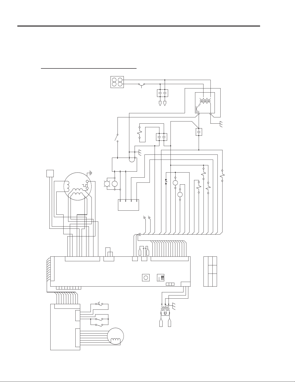
5A.2 ELECTRICAL DIAGRAMS
5A.2.1 Electrical Schematic Diagram - HY-5G
5B-4
(2/02)
Page 7

HYPERSTEAM MODEL HY-5G
Timer
ON
J7
P7A
RED
BLUE
BLUE
BLUE
BLUE
BLUE
BLUE
BLUE
BLUE
BLUE
WHITE
RED/BLU
BLK/RED
BLUE
RED/BLK
WV5
WV2BLACK
BLUE
B
LACK
WHITE
BROWN
GRN/YEL
RED
RED
BLACK
ORANGE
BLACK
BLACK
BLACK
RED
GREEN
WHITE
WHITE
RED
MOTOR CAP
FAN MOTOR
MOTOR ASSY.
P/N 096740
P/N 096857
P
/N 119815
P/N 070178
P/N 070178
P/N 088865
P/N 096857
1
1
1
1
1
1
1
1
1
1
T2-8
T2-10
T2-6
T2
WHITE
BLACK
T2-5
T2-1
20VAC CT
GRN/YEL
WHT/ORN
WHT/ORN
RED
BLUE
BLUE
BLUE
BLUE
BLUE
B
LUE
WHITE
BLACK
BLACK
WHITE
GRN/YEL
WHT/ORN
WHT/ORN
LO PROBE
HI PROBEBLK/BLU
WHT/BLU
BLACK
WV6
BLACK
RED/BLU
WV2
WV1
WHITE
RED
BLACK
RED
GREEN
BLACK
BLACK
WHITE
RED
RED
BLACK
ORANGE
BROWN
GRN/YEL
21
D
IAGNOSTIC
SELECT
STEAMER
SELECT
TMRMOT 2
T
MRMOT 1
24
21
22
11
12
READY B
READY A
DRSW R2
DRSW R1
DRSW L2
DRSW L1
RED
BLUE
BLUE
BLUE
BLUE
BLUE
BLUE
BLUE
BLUE
RED
B
LUE
BLUE
BLUE
BLUE
BLUE
BLUE
RED
P/N 119871
P/N 119868
P/N 123120
J1
TSTAT
DOOR RIGHT
DOOR LEFT
+12VDC
LOW PROBE
HIGH PROBE
J7
J2
J
6
J4
J5
J9
J8
J5A1
J5B1
LOW PROBE
HIGH PROBE
EDUCTOR VALVE
FILL VALVE
137221 STEAMER CONTROL
BOARD
1
19817 LIGHT AND
TIMER BOARD
+5VDC
FAN / SPRAY
FILL
LOW POWER
HIGH POIWER 2
EDUCTOR
DRAIN
HIGH POWER 1
24VAC
P/N 125788
R
ED
P
/N 123123
P/N 090827
P/N 090827
P/N 123122
P/N 096826
P/N 096812
HY5G INTERCONNECT DOMESTIC
24-SEPT-2001
P/N 106233
P/N 119813
P/N 096892
BLACK
BLACK
WHITE
WHITE
BLACK
T1-COM
T1-120
T1-120
T1-COM
BROWN
BROWN
BLK/ORN
BLK/ORN
RED
K1-4
K1-4
K1-2
K1-2
K1-1
K1-1
K1-0
ORANGE
BLK/ORN HL1-NC
HL1-C
T1-24LO GRN/YEL
T1-24HI
BLACK
GRN/YEL
BLACK
T1-24LO
T1-24HI
T
B1
HL1
24VAC CUTOUT
K1
T1
24VAC
HIGH LIMIT
L2
L
1
B
LACK
WHITETB1-1
TB1-2
P/N 003887
P/N
CB1-2
CB1-1
PILOT CUTOUT
P/N 119814
K3
E-GND
GRN/YEL
BLACK
BLACK
P/N 106627
BROWN
WHITE
GV1-2
GV1-1
HIGH POWER #1
GV1
G
RN/YEL
GRN/YEL
GRN/YEL
GRN/YEL
P/N 085153
P/N 096705
IGNITION PLUG
IGNITION MODULE
WHITE
IGN-9
IGN-6
IGN-5
IGN-5
I
GN-4
IGN-4
ORANGE
ORANGE
IGN-3
IGN-2
IGN-1
IGN
BLUE
BLUE
BLACK
SW3-D
P/N 087951
BLUE
ORANGE
BLUE
BLACK
SW3-B
SW3-C
SW3-C
SW3-A
PV-TH
MV-TR
MV-TH
WHITE
BLK/RED
SW3
PILOT SWITCH
MAIN VALVE(NAT)
GV2
PV-TR
BLUE
BLUE PV-TR
RED/BLK
K
3-0
K3-1
K3-1
BLACK
BLACK
B
LUE
K3-0 BLUE
BLACK
BLACK K3-8
K3-8
WHITE
WHITE K3-4
K3-4
BLACK K3-6
WHITE K3-2
P/N 098443
DRAIN VALVE
P/N 074594
WHITE
RED
DV1-1
DV1-2
K4-2
K4-6
BLK/ORN
GRN/YEL
BLACK
BLACK
GRN/YEL
K4-1
K4-4
K4-8
K4-8
K4-4
DRAIN RELAY
P/N138420
K4
WHT/RED K4-0
T2-2 WHITE
T2-4 BLACK
WV3
WV4
BLUE
BLK/GRN
P/N 090827
SPRAY VALVE
P/N 130399
P/N 130397
P/N 130398
11
BLU/WHT
BLK/GRN
BLK/ORN
WHT/RED
RED/WHT
RED
BLACK
ORANGE
BROWN
GRN/YEL
BLK/BLU
W
HT/BLU
RED
BLUE
BLUE
RED
BLACK
*KEY*
ORANGE
RED
BROWN
RED
VIOLET
BROWN
WHITE
YELLOW
BLUE
WHITE
YELLOW
BLUE
VIOLET
BROWN
BROWN
RED
RED
ORANGE
BLACK
Electrical Diagrams
5A.2.1 Interconnect Block Diagram - HY-5G
(2/02)
5B-5
Page 8

HYPERSTEAM MODEL HY-5G/(2)HY-5G
Diagnostics
5B.3 DIAGNOSTICS
Diagnostic procedures are the same for all Steamer Ovens. Refer
to Section 4.2.
5B.4 ASSEMBLY/DISASSEMBLY PROCEDURES
GENERAL INFORMATION:
The following procedures are based upon having access to the
steamer on all four sides. If the steamer is installed between other
appliances and there is not adequate room on the sides for access,
the steamer must be pulled out from its position to gain proper
access.
Care should be exercised in moving the steamer so as not to stress
or pull on electrical, w
ater or gas connections.
5B.4.1 Side Panels
Right Side (Louv
Left Side (Smooth):
Please refer to Section 4.3, Paragraph 4.3.1 for Assembly/
Disassembly procedures.
5B.4.2 Top Cover
Single (or Double Stack Upper): P/N 138536
Bracket, Top Retainer
P/N 123156 (qty 2)
Please refer to Section 4.3, Paragraph 4.3.2 for Assembly/
Disassembly procedures.
Double Stack (2)HY
1.
Disconnect power to the steamers.
2. Remove right and left side covers.
3. On bac
4. In upper unit, disconnect clean hose that comes through
5. Remo
6. Remo
7. Remove lower unit top panel.
k of units, remove vent tube and drain box.
bushing. Remove clamp from hose.
ve four bolts and flat washers.
e top unit.
v
-5G Lower Unit T
ered): P/N 138532
P/N 138534
op Panel Removal
(2/02)
5B.4.3 Adjustable Legs
P/N 042505
Please refer to Section 4.3, Paragraph 4.3.4 for Assembly/
Disassembly procedures.
5B-7
Page 9

HYPERSTEAM MODEL HY-5G/(2)HY-5G
Assembly/Disassembly Procedures
5B.4.4 Pilot Switch (SW3)
P/N 087951
Please refer to Section 4.3, Paragraph 4.3.5 for Assembly/
Disassembly procedures.
5B.4.5 Main Gas Valve (GV2) and
Gas Pressure Adjustment
Natural: P/N 098443
Propane:
1. Turn off gas and electric power to steamer.
2. Remove the right side panel.
3. Turn the manual gas shut-off valve to the OFF position.
P/N 098444
4. Note the positions of wires connected to terminals of the
o gas solenoid valves, then disconnect the wires.
tw
5. Disconnect the four wires from the main gas valve.
They are:
blue:
white: Terminal (PV) TH
black: Terminal (MV) TR
red:
6. Using open-ended wrenches to loosen the compression
nuts, remove the five sections of aluminum tubing between
the valve and piping assembly and the steam generator
manifold assembly. Be careful not to excessively move or
bend the aluminum tubing.
7. With a pipe wrench or ChannelLock, open the pipe union
between the main gas valve and the manual gas shut-off
valve. Remove the assembly.
8. With the main gas valve held in a vise, ChannelLock or pipe
wrench, use a ChannelLoc
both sides of the main gas v
Terminal (PV) TR
Terminal (MV) TH
k to remo
.
e
alv
e the nipples from
v
5B-8
To Install:
9.
Remo
old valve and install on the side of the new valve, using pipe
thread compound.
e the elbo
v
w compression fitting from the side of the
(2/02)
Page 10

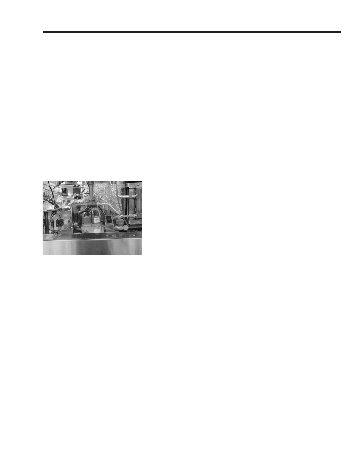
Figure 1.
Gas Pressure Regulator
Adjustment Screw
HYPERSTEAM MODEL HY-5G/(2)HY-5G
Assembly/Disassembly Procedures
10. Screw in and tighten the nipples into both sides of the main
gas valve using pipe thread compound.
IMPORTANT: The elbow and elbow installed on the end of the
valve near the adjustment screw must be positioned at 10 degrees
away from vertical, for correct installation of the assembly back into
the steamer.
11. Using a pipe wrench or ChannelLock, reconnect to the
union near the manual gas shut-off valve and tighten.
DSC00003
12. Attach all aluminum tubing and tighten compression nuts
with an open-ended wrench.
13. Plug in the four terminal wires to the main gas valve, per
step 5 on page 5B-10.
14. Plug in wires at the terminals of the gas solenoid valves.
Figure 2.
Gas Pressure Tap
with Plug
138585A
Gas Pressur
e Adjustment:
Adjust the gas pressure after installing the main gas valve.
1. Remove the gas pressure tap plug (Figure 2) on gas man-
old.
if
2. Connect manometer to gas pressure tap.
3. Remo
ve cap from gas pressure regulator adjustment screw
on the main gas valve (Figure 1). Adjust the gas pressure
regulator screw until the manometer reads 3.2" W.C. for
natural gas or 10.5" W.C. for propane gas. Turn the adjustment screw in to increase pressure and out to decrease
pressure
4. Install cap on pressure regulator scre
manometer and install manif
.
w. Disconnect
old plug.
5B.4.6 Igniter Module
P/N 085153
Please ref
er to Section 4.3, P
aph 4.3.7 f
r
ag
ar
or Assemb
ly/
Disassembly procedures.
(2/02)
5B-9
Page 11

HYPERSTEAM MODEL HY-5G/(2)HY-5G
Assembly/Disassembly Procedures
5B.4.7 Pilot Burner Replacement/
Current Check/Adjustment
Natural Gas: P/N 098641
Propane: P/N 098642
Please refer to Section 4.3, Paragraph 4.3.8 for Assembly/
Disassembly procedures.
5B.4.8 Steam Generator Manifold Assembly
Weldment Only: P/N 138523
Complete Assembly: See Page 5B-3/5B-4
and 5B-38
NOTE: The complete manif
weldment with the following parts installed. Burner jets for the
chosen gas type and altitude; flame holders, and pilot burner, for
the chosen gas type.
1. Turn off gas and electric power to the steamer.
2. Remove the right side panel.
3. Turn the manual gas shut-off valve to the OFF position.
4. Disconnect the igniter cable from the pilot burner. It is a fric-
tion fitting similar to a spark plug wire.
5. Using open-ended wrenches, remove the five sections of
aluminum tubing between the valve and piping assembly
and the gas gener
6. Remove the two screws securing the pilot burner’s mount-
acket to the manifold, and remove the pilot burner.
ing br
7. Use a nut driver or socket wrench to remove four bolts
which hold the manifold assembly to the steam generator.
old assembly consists of the manifold
ator manif
old assemb
ly.
5B-10
8. The manifold assembly may be removed for inspection,
component replacement or assembly replacement.
o Install:
T
9.
If a ne
the tw
to the manif
w manifold assembly is being installed, first remove
ner’s mounting bracket
ws secur
o scre
old, and remo
ing the pilot b
e the pilot b
v
ur
ur
ner
.
(2/02)
Page 12
HYPERSTEAM MODEL HY-5G/(2)HY-5G
Table of Contents
10. Carefully fit the manifold assembly in place on the steam
generator, so that the flame holders are not damaged by
striking the radiation shield. Install and tighten four bolts to
secure the manifold in place.
11. Fit the pilot burner in position under the bottom of the man-
ifold and install two screws to hold its mounting bracket in
place.
12. Reconnect five sections of aluminum tubing between the
valve and piping assembly and the manifold assembly. Use
open-ended wrenches to tighten the compression nuts.
13. Connect the igniter cable to the pilot burner.
5B.4.9 Gas Solenoid Valve
P/N 099906
Main Gas Valve
DSC00006
1. Turn off gas and electric power to the steamer.
2. Remove the right side panel.
3. Turn the manual gas shut-off valve to the OFF position.
4. Note the positions of wires connected to ter
minals of the
two gas solenoid valves, then disconnect the wires.
e.
5. Disconnect the f
our wires from the main gas v
alv
They are:
blue: Terminal (PV) TR
white:
Terminal (PV) TH
black: Terminal (MV) TR
red: Terminal (MV) TH
6. Using open-ended wrenches to loosen the compression
nuts, remove the five sections of aluminum tubing between
the valve and piping assembly and the steam generator
manifold assembly. Be careful not to excessively move or
bend the aluminum tubing.
7. With a pipe wrench or ChannelLoc
k, open the pipe union
between the main gas valve and the manual gas shut-off
. Remove the assembly.
e
alv
v
(2/02)
8. With the tee or elbow near the solenoid valve being
replaced held in a vise
ChannelLoc
k to disconnect the v
, ChannelLoc
k or pipe wrench, use a
e from the nipple
alv
.
5B-11
Page 13

HYPERSTEAM MODEL HY-5G/(2)HY-5G
Assembly/Disassembly Procedures
To Install:
Gas Solenoid Valves
HY-5G
9.
Remove the elbow compression fitting from the side of the
old valve and install on the side of the new valve, using pipe
thread compound. Remove the compression fitting from the
end of the old valve and install on the end of the new valve,
using pipe thread compound.
10. Mount the valve back onto the nipple, using pipe thread
compound.
G70
11. Using a pipe wrench or ChannelLock, reconnect to the
union near the man
ual gas shut-off valve and tighten.
12. Attach all aluminum tubing and tighten compression nuts
with an open-ended wrench.
13. Plug in the four terminal wires to the main gas valve, per
step 5 on page 5A.1-13.
14. Plug in wires at the terminals of the gas solenoid valves.
5B.4.10 Steam Generator Drain Valve
P/N 074594
Removal:
1. Turn off steamer power.
2. Disconnect hoses from the dr
ain valve and remove from
the mounting bracket.
3. Replace hose adapters if damaged.
Installation:
1. Wr
ap pipe threads
, of the hose adapters
, with pipe thread
tape (Teflon tape).
2. Install the hose adapters and drain valve in the reverse
order of removal.
5B.4.11
Water Flow Reducer
P/N 112720
Please ref
er to Section 4.3, P
aragraph 4.3.10 for Assembly/
Disassembly procedures.
5B-12
(2/02)
Page 14

HYPERSTEAM MODEL HY-5G/(2)HY-5G
Assembly/Disassembly Procedures
5B.4.12 Dual Water Inlet Valves
2 way: P/N 071235 (qty 1)
1 way: P/N 100934 (qty 1)
Please refer to Section 4.3, Paragraph 4.3.11 for Assembly/
Disassembly procedures.
5B.4.13 Water Inlet Valve Coil
If a solenoid coil in the water inlet valve is defective, replace the
valve. Refer to Section 4-3, Paragraph 4.3.11.
5B.4.14 Steam Generator
With Insulation Blanket, Water Level Probes and
High Limit Thermostat: P/N 138577
Weldment Only: P/N 138521
1. Shut off power, water and gas supply to steamer.
2. Remove both side panels.
3. Turn manual gas shut-off valve to the OFF position.
4. Disconnect the long steam hose from the steam generator.
Use hose clamp pliers to loosen the clamp on the hose and
slide it down the hose for later use. Remove the hose from
the steam generator fitting. Repeat this step for the short
steam hose.
5. Unplug the igniter cable from the igniter porcelain heat sen-
sor with a do
a spark plug wire.
6. Remo
7. Remo
8. Remove drain valve and steam generator drain hose.
v
graph 5B4.8.
v
Please ref
Disassembly procedure.
wnward motion. It is a friction fitting similar to
e steam gener
o scre
e tw
er to Section 4.3, P
ator manif
ws and remove radiation shield.
old assembly. See para-
raph 4.3.9 for
ag
ar
(2/02)
ertical gas flue (if (2)HY-5G) from steam genera-
e v
9. Remo
10. To remove each flue, lift the vertical flue enough to clear lip
v
tor by removing two screws which hold the vertical flue
mounting bracket to the rear panel. Remove two screws
tical flue to the horizontal flue.
secur
on hor
ing the v
ontal flue
iz
er
.
5B-13
Page 15

HYPERSTEAM MODEL HY-5G/(2)HY-5G
Assembly/Disassembly Procedures
11. Remove drain vent pipe. Remove one screw at the top of
the vent pipe and lift pipe out.
12. Remove drain box. Remove drain box mounting screw on
back panel. Loosen and move hose clamp inside the frame
on the left side. Pull drain box out of steamer.
13. Remove two 8-32 screws securing the live connection
assembly to the inside of the back panel. Disconnect wires
from the assembly.
14. Remove two 8-32 screws securing water inlet valve assembly to the back panel of the steamer.
15. Remove four 10-32 truss head machine screws and
remove back panel.
16. Disconnect the wires from the side of the steam generator
which are attached to the high heat thermostat.
17. Slide back the rubber boots covering the water level probe
terminals to expose the terminal wires. Use a 5/16 nut driver to loosen, but not remove, the nuts holding the wires on
the probe terminals. Un-snap the wires by gently pulling on
the terminals. With an open-ended wrench, disconnect high
and low water level probes from the steam generator. Clean
or replace probes.
18. At the left side of the steamer
loosen the clamp on the w
wn the hose for later use. Pull the hose off the end of the
do
trap tube. Then use an open-ended wrench to disconnect
the trap tube from the fitting on the steam generator.
19. Remove two bolts holding steam generator braces to the
steamer base.
CAUTION: Because of the weight of the steam generator,
two people are required to lift and move it.
20. The steam generator(s) may now be removed. It is suggested that the
This is easier and avoids damage to adjacent components.
21. The steam generator is covered with an insulation blanket.
Carefully remove this blanket without tearing so that it can
be used on its replacement.
y be removed from the rear of the steamer.
, use hose clamp pliers to
ater fill/clean hose and mo
ve it
5B-14
22. Remove the water fill brass fitting, elbow and hose fitting,
high heat thermostat and safety valve from old steam generator weldment and install them on the new steam generator weldment.
(2/02)
Page 16

HYPERSTEAM MODEL HY-5G/(2)HY-5G
Assembly/Disassembly Procedures
To Install:
23.
24. Slide the steam generator into position from the back of the
25. From the back of the steamer, fasten the steam generator
26. To install all parts and components reverse the removal
27. Connect the steam hose by easing the end of the hose onto
Carefully wrap the insulation blanket onto the new steam
generator weldment. Make sure it fits snugly with no air
spaces between the blanket and the steam generator.
Fasten seams with aluminum duct tape.
CAUTION: Because of the weight of the steam generator,
two people are required to lift and move it.
steamer
into place on the steamer base using the two bolts and a
socket wrench (with an extension). An open-ended wrench
ma
procedures of steps 6 through 18 abo
the steam generator fitting. Make sure the hose engages
the fitting all the way. Using hose clamp pliers, slide the
hose clamp down the hose and position it so that the clamp
is no more than 1/4 inch from the end of the hose. Repeat
this step for the long steam hose.
.
y also be used.
ve.
28. Fasten the igniter spark cable to the pilot light porcelain
heat sensor.
5B.4.15 High Limit Thermostat
P/N 096892
Please ref
Disassemb
5B.4.16 Steam Generator Probes (High and Low Water)
Please refer to Section 4.3, Paragraph 4.3.16 for Assembly/
Disassembly procedures.
er to Section 4.3, Paragraph 4.3.14 for Assembly/
ly procedures
P/N 070178
.
(2/02)
5B-15
Page 17

HYPERSTEAM MODEL HY-5G/(2)HY-5G
Assembly/Disassembly Procedures
5B.4.17 Supply Voltage Terminal Block
P/N 003887
1. Turn off the power to the steamer.
2. Remove the four wires going to the terminal block with a flat
blade screwdriver.
3. The terminal block is held to the bracket on the back panel
with one slotted screw. To remove, turn screw until device is
free.
o Install:
T
4.
5. Reattach wires.
5B.4.18 Control Voltage Transformer
Please refer to Section 5.1, Paragraph 5.1.4.20 for Assembly/
Disassembly procedures
5B.4.19 Timer Assembly
Please refer to Section 4.3, Paragraph 4.3.17 for Assembly/
Disassembly procedures.
5B.4.20 Light and Timer PC Board
Position terminal block and screw in.
P/N 106233
P/N 119815
.
P/N 096826
Timer Fastener Nut
P/N 101145
P/N 119817
5B-16
raph 4.3.12 for Assembly/
ag
Please ref
Disassembly procedures.
5B.4.21 Steamer Control PC Board
Please refer to Section 4.3, Paragraph 4.3.13 for Assembly/
Disassembly procedures.
er to Section 4.3, P
P/N 119801
ar
(2/02)
Page 18

HYPERSTEAM MODEL HY-5G/(2)HY-5G
Assembly/Disassembly Procedures
5B.4.22 Fan
P/N 096790
Please refer to Section 4.3, Paragraph 4.3.18 for Assembly/
Disassembly procedures.
NOTE: There are two fans on the HY-5G/(2) HY5-G steamers.
5B.4.23 Fan Motor Assembly
P/N 096740
Motor Insulator
P/N 094135
Motor Shaft Seal
P/N 096868
Oil Slinger Washer (Part of Fan Motor Assembly)
Please refer to Section 4.3, Paragraph 4.3.19 for Assembly/
Disassemb
ly procedures.
Steam Gener
Mounted On Steam P
ator Ready
(HY-5G Shown)
Thermostat
t
or
5B.4.24 Motor Starting Capacitor
3 mfd: P/N 096813
Please refer to Section 4.3, Paragraph 4.3.20 for Assembly/
Disassembly procedures.
IMPORTANT: Be sure to use the correct value capacitor: 3 mfd
at 250 volts.
5B.4.25
Steam Generator Ready Ther
mostat
P/N 099947
This thermostat is attached to the cavity steam port by two 6-32
screws.
1. Turn off power to the steamer.
2. Unplug the tw
o wires from the ther
mostat from the wiring har-
ness.
3. Using a flat b
lade screwdriver, remove the two 6-32 screws
holding the thermostat to the steam port.
4. T
o install a new thermostat, use a small amount of heat sink
compound (1 drop), applied to bottom of thermostat. Seat the
thermostat on the steam port and fasten with the two screws
G41
(as abo
ve).
5. Plug the thermostat into the wiring harness.
(2/02)
5B-17
Page 19

HYPERSTEAM MODEL HY-5G/(2)HY-5G
Assembly/Disassembly Procedures
5B.4.26 Steam Port
P/N 106511
Steam Port Gasket
P/N 099250
Please refer to Section 4.3, Paragraph 4.3.22 for Assembly/
Disassembly procedures.
NOTE: There is one (1) steam port (per cavity) on the
HY-5G/(2)HY-5G Steamers.
5B.4.27 Cavity Hose Assemblies
Steam Hose, Long: P/N 138445
Steam Hose, Short: P/N 138446
Please refer to Section 4.3, Paragraph 4.3.23 for Assembly/
Disassembly procedures.
NOTE: There are two (2) steam hose assemblies (per cavity) on
the HY-5G/(2)HY-5G Steamers, one to each steam port.
5B.4.28 Door Removal/Installation/Alignment
Door Assy, Complete: P/N 125922
Please refer to Section 4.3, Paragraph 4.3.24 for Assembly/
Disassembly procedures.
5B.4.29
Please refer to Section 4.3, Paragraph 4.3.26 for Assembly/
Disassembly procedures.
5B.4.30
Please refer to Section 4.3, Paragraph 4.3.25 for Assembly/
Disassemb
5B.4.31 Door Gasket
Please refer to Section 4.3, Paragraph 4.3.27 for Assembly/
Disassembly procedures.
Door Switch
P/N 096857
Door Reversing Procedures
ly procedures
P/N 125907
.
5B-18
(2/02)
Page 20

HYPERSTEAM MODEL HY-5G/(2)HY-5G
Assembly/Disassembly Procedures
5B.4.32 Door Components (common to all Steamers)
Door Handle
P/N 129723
Door Cam
P/N 074252
Door Spacer
P/N 071206
Magnet and Block Assembly
P/N 069762
Screws
P/N 005764
Please refer to Section 4.3, Paragraph 4.3.28 for common Door
Component part numbers.
Door Components (unique to HY-5G/(2)HY-5G)
U-Channel Assembly
P/N 125924
Outer Door Panel
P/N 125923
Inner Door Panel
P/N 125927
Door Insulation Board
P/N 125926
Please refer to Section 4.3, Paragraph 4.3.28 for Assembly/
Disassembly, Alignment procedures and common Door
Component par
5B.4.33 Door Spring
Please refer to Section 4.3, Paragraph 4.3.29 for Assembly/
Disassemb
5B.4.34 Door Latch Pin
Please refer to Section 4.3, Paragraph 4.3.30 for Assembly/
Disassembly procedures.
5B.4.35 Wiring Harnesses
t n
or par
F
page 5B-7/5B-8.
Please ref
Disassembly procedures.
t numbers.
P/N 078911
ly procedures
P/N 078914
Jam Nut
P/N 003823
umbers
er to Section 4.3, P
, ref
.
er to Interconnect Bloc
am,
k Diag
aph 4.3.31 for Assembly/
r
ag
ar
r
(2/02)
5B-19
Page 21

HYPERSTEAM MODEL HY-5G/(2)HY-5G
Assembly/Disassembly Procedures
5B.4.36 Cleaning System Eductor
P/N 086460
Removal:
1. Turn off steamer power.
2. Disconnect hoses from the eductor and remove from the
mounting bracket.
3. Replace hose adapters if damaged.
Installation:
1. Wrap pipe threads, of the hose adapters, with pipe thread
tape (T
2. Install the hose adapters and eductor in the reverse
order of removal.
eflon tape).
5B-20
(2/02)
Page 22

HYPERSTEAM MODEL HY-5G
1
4
6 78
5
10
11
12
1
3
14
15
1
6
17
18
20 19
23
9
Parts Identification
External Cabinet
PARTS IDENTIFICATION
Key Description Part No.
1 Right Side Panel 138532
2 Door Assy, Complete 125922
3 Door Handle 129723
4
Door Gasket 125907
5 Left Pan Rack 125901
6 Blower Cover/Rack (fan baffle) 125902
7
8 Door Pin Lock Nut 003823
Door Latch Pin
078914
9 Left Side Panel 138534
10 Timer Knob 123100
ront Panel Overlay 138424
11
F
12 Top Panel 138536
x - Item not depicted/called out in drawings
(2/02)
PARTS IDENTIFICATION
Key Description Part No.
13 Funnel, Delime 106624
14 Back Panel 138530
15 Optional Table 100913
16
17 Timer Fastener Nut 101145
18 Drain Tube 138546
19 W
20 Water Valve Double 071235
x Motor Shaft Seal 096868
x Optional Legs 041121
x
x Cavity Fan 096790
Drip Tray 094151
e Single 100934
alv
V
ater
Groen De-limer/De-scaler
114800
5B-21
Page 23

HYPERSTEAM MODEL (2)HY-5G
2
2
8
5
1
3
13
3 PLCS
2 PLCS
2 PLCS
4
13
14
10
7
6
8
5
7
22
4
13
13
1
3
12
11
3
1
7
19
18
17
16
20
20
15
16
Parts Identification
Parts listed below only apply to model (2) HY-5G. Common parts are listed on page .
External Cabinet
PARTS IDENTIFICATION
Key Description Part No.
1 Table 138759
2
3 Flue, Inside 138406
4 Flue, Vertical 138401
5
6 Hose 2" 090742
7 Clamp 2" 015663
8 Hose Vent 138463
Spacer 138594
ent Pipe
ain and
Dr
V
138458
5B-22
Key Description Part No.
9 Drain T-Connector 126003
10
11 Clamp 099284
12 Bullet Foot 042505
13 W
14 Hose Connector 101189
15 Overlay Top
16 Overlay Bottom
PARTS IDENTIFICATION
Hose Drain 138471
ater Hose
138470
(2/02)
Page 24

HYPERSTEAM MODEL HY-5G
6
25
6
6
9
1
8
19
2
1
16
1
7
1
2
3
11
12
4
31
SECTION A-A
SECTION B-B
15
14
13
20 7
5
Parts Identification
Electrical Parts; Steam Hoses
Except items 10-12, all parts occur in upper and
lower units of (2)HY-5G.
10-12 are in lower units only.
PARTS IDENTIFICATION
No. Description Qty. Part No.
1 Cover, Control Panel 1 119806
2 Standoff, Hex Male/Female 1 119826
6-32 x 3/4"
3 Light and Timer PC Board Assy 1 119817
4 Knob, Timer 1 123100
5 Nut Rotary Shaft Seal 1 101145
096826
, 60 Hz
Timer
6
7 Steamer Control PC Board Assy 1 119801
8 Standoff, Hex Male/Female 2 119827
6-32 x 1-1/4"
9 Door Switch (Note 2) 2 096857
10 Funnel Assemb
Clamp, Constant
11
12 Hose, Boiler Cleanout 1 106580
1-1/2" I.D. x 8-1/2" Long
13 Switch Rock
14 Fitting, Steam (Steam Port, Front) 1 138418
15 Gasket, Steam Port 1 099250
16
17 Top Electrical Assembly 1 138551
(Pilot Ignition)
(Note 3)
Universal Thermostat 1 099947
(Ready
Ther
ly 1 106624
ension CTB-19
T
er w/LED
mostat)
1
126011
2
1 087951
PARTS IDENTIFICATION
No. Description Qty. Part No.
19 Motor Assembly (Fan Motor) 1 096740
20 Bottom Electr
, Steam Inlet
Hose
21
1-1/2" I.D. x 7-7/8" Long
Clamp
22
23 Hose Steam 1 138445
1-1/2" I.D
24 Main Power Assembly 1 138429
25 Motor Insulator 1 094135
26 Seal, Steamer Motor (Note 4) 1 096868
ube 1-1/2" O
T
27
28 Valve-Drain, 1/2" I.D. 1 074594
31 Igniter Cable 1 106495
TES:
NO
or Part Numbers of har
F
1.
see page 5B-5.
2. One door switch is mounted on each side of the steam-
3. Mounting flange (shown by dotted lines) is covered by
4.
.
vity
er ca
cavity insulation blanket.
Before installing seal, saturate it with about 0.1 ounce of
Lubricant, Motor Shaft, Groen P/N 099948.
ical Assemb
, Constant Tension, CTB-47 4 127526
x 10-1/2" Long
.
x 45
.
.D
ly
1 138561
138446
1
° 1 138412
, jumpers and cab
nesses
les,
(2/02)
5B-23
Page 25

HYPERSTEAM MODEL HY-5G
T
ORQUE:
30-32 IN-LBS
6 PLCS
4
6
5
6
3
1
2
Parts Identification
Rear Cover And Vent Assembly
5B-24
Description
No.
1 Weldment, Rear Cover 1 138530
2 Bracket, Steam Vent 1 138413
Scre
3
4 Tube, Steam Vent 1 138544
Hose, 3/4" I.D
5
Clamp
6
CTB-24
7 Loctite #242 A/R 073242
NOTES:
Apply one drop of item #7 (Loctite) to item #3 (Screw) prior to assembly.
1.
PARTS IDENTIFICATION
w 10-32" x 3/8" LG Truss HD 6 004173
, Hose Constant
x 4-1/2" LG
.
Tension 2 127524
Qty.
1
Part No.
138463
(2/02)
Page 26

HYPERSTEAM MODEL HY-5G
5
3
4
2
1
6
7
TORQUE: 8-10 IN-LBS
12 PLCS
TORQUE: 8-10 IN-LBS
9
10
Parts Identification
Top Electrical Assembly
PARTS IDENTIFICATION
No. Description Qty. Part No.
1 Weldment, Electrical Components 1 138453
Bracket
2 Transformer, 75VA, 120V Primary 1 106233
24V Secondary
3 Relay, Cutout 24V 1 119814
119813
, 12VDC
y
Rela
4
ransformer, 20 VAC 1 119815
T
5
6 Screw, 6-32 x .375 LG Hex 12 069788
Slotted Washer Head
7 Screw, 6-32 x .250 LG Hex 2 069777
Slotted Washer Head
Ignition Module 1 085153
8
9 Clamp, Loop 1/2" Dia. Nylon 2 089343
10 Weldment, Mounting Support 1 138454
Electr
11 Loctite #242 A/R 073282
NOTES:
1. Apply one drop it item #11 (Loctite) to items #6 & 7 (screws) prior to assembly.
ical Panel Bracket
1
(2/02)
5B-25
Page 27

HYPERSTEAM MODEL HY-5G
1
1
3
2
2
TORQUE: 8-10 IN-LBS
3 PLCS
4
4
3
Parts Identification
Bottom Electrical Assembly
5B-26
PARTS IDENTIFICATION
No. Description Qty. Part No.
1 Weldment, Electrical Components 1 138455
Bottom Bracket
2 Screw 6-32 x .375 Hex Slotted 3 069788
asher Head
W
, DPST No. 24VDC Panel 1 138420
Relay
3
4 Capacitor Foil 3 MFD 1 096813
Loctite #242
5
NOTES:
Apply one drop it item #5 (Loctite) to item #2 (screw) prior to assembly.
1.
A/R
073282
(2/02)
Page 28

HYPERSTEAM MODEL HY-5G
10
4
8
5
12
7
3
3 7
1
2
5
TORQUE:
8-10 IN-LBS
TORQUE:
8-10 IN-LBS
Parts Identification
Main Power Box
PARTS IDENTIFICATION
No. Description Qty. Part No.
1 Weldment, Main Power 1 138456
Box Bracket
2 Terminal Block, 2-Pole 1 003887
3 Lug, Ground 1 129714
4 Fuse Holder 1 077854
5 Bushing, Snap 1/2" I.D. x 5/8" 1 009884
MTG Hole #SB-625-8
6 Bushing Snap 11/16" I.D. x 7/8" 1 012864
MTG Hole #SB-875-11
7 Screw 6-32 x 1-1/4" LG Round 1 011236
Head Machine
8 Screw 6-32 x .375 LG Round 1 009697
9
10 Fuse, 3 AMP 1 077853
11 Loctite #242 A/R 073282
NOTES:
1.
Head Machine
w 6-32 x .375 LG Hex Slotted 2 069788
Scre
Washer Head
Apply one drop it item #11 (Loctite) to items #7, 8 and 9 (screws) prior to assembly.
(2/02)
5B-27
Page 29

HYPERSTEAM MODEL HY-5G
TORQUE:
30-32 IN-LBS
TORQUE:
30-32 IN-LBS
SEE NOTE #1
TOUQUE:
25-30 IN-LBS
SEE NOTE #4
2
11
2 16
16
18
1
7
12
13
10
8
4
2
7
6
7
5
B
B
9
1
Parts Identification
Base Plumbing
ARTS IDENTIFICA
P
No. Description Qty. Part No.
eldment, Base Pan - HY-5G 1 138500
W
1
2 Assembly Delime Eductor - HY-5G 1 138421
, Clamp Eductor 1 106561
Plate
3
4 Screw, 10-32 x .375 LG Truss HD 1 004173
5 Valve, Check .375 Hose Barb 1 138428
6 Hose .375 I.D. x 1.75 LG 1 138448
Clamp, Hose
7
8 Bracket, Drain Valve 1 138592
9 Nut, 10-32 KEPS 2 071256
Valve Solenoid 1/2" NPT 1 074594
10
11 Fitting, Straight 1/2" x 3/4" Hose 1 138441
Beaded Brass
Fitting, 90
12
Hose Beaded Brass
13 Fitting, Hose Barb To Male Pipe 1 069732
3/8" I.D
14 Pipe Dope A/R 078938
15 Loctite #242 A/R 073282
le
, Doub
1/2" NPT x 3/4"
°
Hose x 1/4" NPT
.
Wire
TION
, DW.9.5 2 127527
138442
1
5B-28
PARTS IDENTIFICATION
No. Description Qty. Part No.
16 Eductor, 1/2-14 NPT 1 086460
17 Elbow 90° 1/2-14 x 1/2 Hose Blk 1 106613
HDLP
Male Adapter, 3/8-18 x 3/8 Hose 1 106614
18
Blk HDLP
19 Elbow 90° 1/2-14 x 3/8 Hose 1 139126
BLK HDLP
NOTES:
1. Use ground screw that comes with item 10 (valve
solenoid) to secure item 10 (valve solenoid) to
item 9 (bracket, drain valve).
2. Apply a small amount of item 14 (pipe dope) on threads
of items 11, 12 & 13 pr
3. Apply one drop of item 15 (Loctite) prior to assembly of
items 4 & 9.
Assemb
4.
pointed toward item 2 (delime eductor).
le item 5 (chec
ior to assemb
e) so flo
alv
k v
ly.
w direction arrow is
(2/02)
Page 30

HYPERSTEAM MODEL HY-5G
A
A
B
B
D
D
C
SECTION A-A
SECTION B-B
DETAIL C
1211
2
3
7
14
16
15
1
7
8
9
6
10
1
5 4
5
2 PLCS
TORQUE:
1
8-20 IN LBS
2 PLCS
TORQUE:
18-20 IN LBS
20
18
19
20
Parts Identification
Base Plumbing
PARTS IDENTIFICATION
t No.
ar
P
Qty.
106591
1
1 138449
No. Description Qty. Part No.
11 Retainer, Top 2 123156
12 Screw, 8-32 x 3/8" LG Truss HD 2 005764
13 Screw, 10-32 x 3/8" LG Truss HD 3 004173
14 Plug, 1" Snap-In Unvented 1 139000
oly
P
15 Drain Extension 1 138546
16 Hose 1 125955
Clamp HC-38
17
Hose 3/4" x 7-3/8" LG
18
19 Hose 3/4" x 4" LG 1 138465
20 Clamps CTB-27 4 138457
Description
No.
Funnel Assembly 1 106624
1
2 Door Keeper 1 106531
, 8" x 3/8" LG Pan HD Type “F”
Scre
w
3
4 Hose, Boiler Cleanout 1 106580
Clamp, Hose
5
, Constant Tension 2 127526
CTB-47
6 Weldment, Delime Tube Assembly 1 138415
7 Nut, 10-32 KEPS 1 071256
x 4.0 Long
.
.D
, 3/8 O
Hose
8
9 Clamp, Hose, Double Wire DW-9.5 2 127527
10 Weldment, Top Cover 1 138536
(2/02)
P
ethlene
TS IDENTIFICA
AR
TION
2 126010
1
138464
5B-29
Page 31

HYPERSTEAM MODEL HY-5G
6
25
6
6
9
18
192116
17
1
2
3
11
12
4
31
SECTION A-A
SECTION B-B
6
B
B
AA
23
15
14
13
20 7
5
24
22
8 10
TORQUE:
18-20 IN-LBS
Parts Identification
Electric, Gas and Hose Assembly
PARTS IDENTIFICATION
No. Description Qty. Part No.
1 Valve, Single Water 1 100934
alve, Double Water 1 071235
V
2
3 Screw, 8-32 x 3/8" Truss HD 4 005764
4 Hose, 3/8 I.D. x 64" LG 1 138467
Clamp, Hose Double Wire DW-9.5 2 127527
5
6 Clamp, Hose Constant Tension 4 126095
CTB-19
Hose, 3/8 I.D. x 46" Long 1 138452
7
8 Hose, 3/8 I.D. x 42" Long 1 138468
9 Hose, 1/2 I.D. x 29.0 LG 1 138451
“Delime
To Trap”
10 Clamp, Double Wire DW-11.5 1 127662
11 Reducer, Water Flow (.078 I.D.) 1 088877
Clamp Hose Low Pressure 1 093482
12
1/4 Min 25/32 Max
13 Assembly, Bottom Electrical 1 138561
Assembly, Top Electrical 1 138551
14
15 Assembly, Main Power Box 1 138429
16 Nut, 10-32 Hexagon KEPS 2 071256
17 Washer Flat 10-32 2 010414
18 U-Bolt 1 n87786
5B-30
PARTS IDENTIFICATION
No. Description
19 Nut, 1/4-20 He
xagon KEPS 2 012940
20 Assembly, Gas Train - HY-5G 1 138564
21 Washer, Flat 1/4-20 2 005472
22 Bracket, Switch 1 106451
23 Switch 1 087951
Screw, 8-32 x 3/8" Flat HD 2 127178
24
Undercut Phil
25 Clamp, Hose Constant Tension 1 127522
26
CTB-16
ness, Power (Not Shown) 1 130397
Har
27 Harness Drain (Not Shown) 1 130398
28
Har
, Control (Not Sho
ness
wn) 1
29 Cable Hi Volt Spark Ignition 1 085154
(Not Shown)
30 Loctite #242 A/R 073242
31 Boiler Trap 1 106229
TES:
NO
1. Apply one drop of item 30 (Loctite) prior to assembly of
items 16, 19 & 24.
t item 11 (Reducer) into item 8 (Hose) and secure with
Inser
2.
item 12 prior to assembly of item 8 (Hose) on to unit.
Qty. Part No.
130399
(2/02)
Page 32

HYPERSTEAM MODEL HY-5G
12
10
15
16
17
11
9
13
8
14
7
6
5
1
2
3
4
Parts Identification
Gas Train Assembly
PARTS IDENTIFICATION
No. Description Qty. Part No.
1 Valve, Gas 1 098443
Nipple, 1/2" NPT x 3" Long
2
3 Valve, Gas Manual Shutoff 1 098458
1/2" NPT
4 Nipple, 1/2" NPT x 10" Long 1 005558
5 Elbow, 90° Street 1/2" NPT 1 004185
6 Nipple, 1/2" NPT x 3-1/2" Long 1 008227
Elbo
7
1/2" x 3/8" NPT
ee, 3/8" NPT 1 012794
T
8
9 Elbow, 90° Street 3/8" NPT 1 009853
Automatic Gas Valve, 25V 1 099906
10
, 90° Street 1 005680
w
005553
1
(2/02)
PARTS IDENTIFICATION
No. Description Qty. Part No.
11 Elbow, 90° 3/8" x 1/2" Tube 1 090737
Connection 1/8" MPT x 1/4" 1
12
ube Straight
T
Nipple, 3/8" NPT x 3-1/2" Long
13
14 Nipple, 3/8" NPT x 2" Long 1 005679
15 Connection 3/8" MPT x 3/8" Tube 1 050879
Compression
16 Tube, Gas Lo-Fire - HY-5G 1 138426
17 Tube, Gas Hi-Fire - HY-5G 1 138425
Pipe Dope
18
NOTES:
1. Apply a small amount of item #18 (Pipe Dope) on to pipe
threads prior to assembly.
075055
008128
1
A/R 078938
5B-31
Page 33

HYPERSTEAM MODEL HY-5G
3
2
7
5
6
4
1
Parts Identification
Burner Manifold Assembly
5B-32
PARTS IDENTIFICATION
No. Description Qty. Part No.
ner Manifold 1 138523
1 Bur
2 Burner Jets .0595 orifice 6 099927
Natural Gas
2 Burner Jets .035 orifice 6 099934
Propane Gas
3 Flame Holder 8 056965
ube
Connector 3/8" MPT x 1/2"
4
Compression
Connector 3/8" MPT x 3/8"
5
Compression
Pipe Plug 1/8" NPT He
6
Sunk Head
ner Jets .043 orifice Natural
Bur
7
Gas
ner Jets .025 or
Bur
7
Gas
TES:
NO
1. Flame Holders must point down.
2. Apply Loctite to all threaded connections.
ifice Propane
T
ube
T
x Counter
054493
1
050879
1
010286
1
106523
2
138474
2
(2/02)
Page 34

HYPERSTEAM MODEL HY-5G
B
AA
D
D
B
C
DETAIL C
VIEW D-D
SEE NOTE #1
SECTION A-A SECTION B-B
7
1
2
4
TORQUE:
72-75 IN-LBS
4 PLCS
TORQUE:
30-32 IN-LBS
TORQUE:
30-32 IN-LBS
3
6
8
5
9
Parts Identification
Pilot Burner Assembly
PARTS IDENTIFICATION
No. Description Qty. Part No.
1 Weldmont, Pilot Bracket 1 138571
2 Pilot, Burner Natural Gas 1 098649
2 Pilot, Burner Propane Gas 1 098644
3 Screw, Fillister HD Slot 2 090797
10-32 x 1/4 LG
4 Screw, 8-32 x 3/8 Hex MS 2 069789
Slot Washer HD Cap
Shield, Flame
5
6 Assembly, Burner Manifold 1 138586
Propane
, 1/4-20 x 1/2 Lg
w
Scre
7
Hex HD Cap
(2/02)
1 138466
005608
4
No. Description Qty. Part No.
10 Kit, Conversion To LP Gas 1 079802
NO
1. Apply Item #9 (Label) in approximate location as shown.
2. Assemble Item #10 (Kit Conversion) into primary gas
3. For double stack units double all quantities.
PARTS IDENTIFICATION
8 Tube, Pilot Control 1/4 Dia. 1 138427
Label, Natur
9
Label, Propane Gas Only
9
TES:
e per instr
alv
v
(Item #10).
al Gas Only
uction sheet pro
vided in kit, con
087992
1
087993
1
ersion
v
5B-33
Page 35

HYPERSTEAM MODEL HY-5G
SEE NOTE #2
11
3
2
5
1
4
4
9
5
10
9
7
6
8
2
4
10
Parts Identification
Steam Generator
ARTS IDENTIFICATION
P
No. Description Qty. Part No.
W
1
Insulation, Boliler - HY-5G 1 138588
2
3 Oven Temp Sensor 1 096892
V
4
5 Prove-Water-Combo Oven 2 070178
6 Gasket, Drain 1 106232
Plate
7
NOTES:
Apply a small amount of pipe dope (Item #12) pr
1.
assembly of items 3, 5, 9 & 10.
2. Apply tape (Item #11) after the installation of the boiler
insulation (Item #2), as shown.
eldment, Steam Generator Final
alve Pressure Relief - 1/2 P
, Dr
.S.I. 1 132183
ain
5B-34
138521
1
1 106226
ior to
ARTS IDENTIFICATION
P
No. Description Qty. Part No.
Nut, 5/16-81 He
8
Elbow, 90° 1 090737
9
.375 NPT x .50
Elbo
10
.50 NPT x .75 Hose
11 Tape, Duct 2" Wide Aluminum 35" 042359
12 Pipe Dope A/R 078938
xagon KEPS 4
ube
T
, 90° 1 138442
w
012941
(2/02)
Page 36

F
20
16
17
20
18
21
19
20
15
16
16
1
11
3
10
20
21
SEE
NOTE 2
C
C
HYPERSTEAM MODEL HY-5G
Parts Identification
Double Stack Kit
No. Description Qty. Part No.
1 Stand W/Bullet Feet Assembly 1 138579
2 Weldment, Front Double Stack Leg 2 139002
3 Weldment, Skirt Spacer 1 138594
4 Horizontal Flue Assembly 1 138405
5 Weldment, Vertical Flue 1 138401
6 Clamp 1 106530
7 Screw, 8-32 x 3/8" Long Truss HD 6 005764
8 Bracket, Mounting Verical Flue 1 138409
9 Bushing, Snap 3/4 ID x 1" 1 000453
MTG Hole
eldment,
W
10
11 Auto Clean Assembly W/Door 1 106624
12 Connector Hose 2 Way 3/4" 2 101189
Screw
13
14 Bracket, Top Retainer 2 123156
ain
15 Dr
Hose Drain 2" ID x 2" Long 3 090742
16
17 Weldment, Drain & Steam 1 138458
Vent Tube
18 Hose, 3/4 ID x 4.50 Long 1 138463
19 Hose, Oven 2" ID x 25-1/2" Long 1 138471
20 Clamp Hose 1-3/4" - 2-1/2" Capacity 8 015663
21 Clamp Hose Worm Drive 2 099284
9/16" - 1-1/16" Range
22 Hose, Water 3/8" x 26.5" Long 2 138470
PARTS IDENTIFICATION
Top Cover 1 138536
, 10-32 x 3/8 Long Truss HD 8 004173
ee Assemb
T
ly 2" 1 126003
(2/02)
5B-35
Page 37

TORQUE:
30-32 IN-LBS
37
40
37
39
28
32
34
33
34
38
5 PLCS
SECTION C-C
9
40
39
DETAIL F
HYPERSTEAM MODEL HY-5G
Parts Identification
Double Stack Kit
PARTS IDENTIFICATION
No. Description Qty. Part No.
23 Nut, 1/4-20 KEPS 2 012940
24 Washer, Plain 1/4" 4 005472
25 Screw, 1/4-20 x 3/4 Long Hex HD 4 005609
Cap
26 Bracket, Top Retainer D/S 2 138410
27 Washer, 10-32 2 010414
28 Nut, 10-32 KEPS 3 071256
29 Washer, Plain 3/8" 6 006035
30 Washer, Lock 3/8" 6 005618
31 Screw, 3/8-16 x 5/8" Long 6 005449
Hex Head Cap
32 Weldment, Delime Tube 1 138415
33 Hose, 1-1/2 ID x 2-1/2 Long Boiler 1 106580
Cleanout
, Hose Constant Tension 2 127526
Clamp
34
(CTB-47)
35 Keeper 1 106531
36 Screw #8 x 3/8 Long Pan Phillips 1 106591
Selftapping
37 Hose, 3/8 ID x 1.75 Long 2 138448
38 Tee, Barbed Hose Poly 1 138432
39 Clamp, Hose Double Wire 6 127527
40 Hose, 3/8 ID x 54.0 Long 1 138450
Loctite #242
41
A/R 073242
5B-36
NOTES:
1. Use screws that are currently in back panel to secure item 8
(bracket mounting vertical flue) to back panel.
2. One hose (item 16) and two clamp hoses (item 20) will be
shipped inside of unit for assembly onto unit at customer site.
3. Apply one drop of Loctite (item 41) prior to assembly of items
7, 13, 23, 25, 28, 31 & 36.
(2/02)
Page 38

HYPERSTEAM MODEL (2)HY-5G
TORQUE:
18-20 IN-LBS
T
ORQUE:
2
30-240 IN-LBS
4 PLCS
TORQUE:
18-20 IN-LBS
3
13
29
30
12
13
13
4
22
5
8
7
31
7
7
14
DETAIL A
DETAIL G
SECTION B-B
A
B
B
E
E
D
D
3 PLCS
4 PLCS
4 PLCS
2 PLCS
2 PLCS
SEE
NOTE1
Parts Identification
Double Stack Kit
PARTS IDENTIFICATION
.
Description
No.
2 Weldment, Front Double Stack Leg 2 139002
4 Horizontal Flue Assembly 1 138405
eldment,
W
5
6 Clamp 2 106530
7 Screw, 8-32 x 3/8" Long Truss Hd 6 005764
ac
Br
8
12 Connector Hose 2 Way 3/4" 2 101189
13 Screw, 10-32 x 3/8 Long Truss Hd 8 004173
Vertical Flue 1 138401
ket, Mounting Vertical Flue 1 138409
Qty
Part No.
(2/02)
5B-37
Page 39

HYPERSTEAM MODEL HY-5G/(2)HY-5G
24
25
2827
26
35
36
2
SECTION D-D
4 PLCS
4 PLCS
TORQUE:
230-240 IN-LBS
TORQUE:
72-75 IN-LBS
312330 29
SECTION E-E
Table of Contents
Double Stack Kit
PARTS IDENTIFICATION
No. Description Qty. Part No.
14 Bracket, Top Retainer 2 123156
22 Hose, Water 3/8" x 26.5" Long 2 138470
23 Nut, 1/4-20 KEPS 2 012940
24 Washer, Plain 1/4" 4 005472
25 Screw, 1/4-20 x 3/4 Lg Hex Hd Cap 4 005609
26 Bracket, Top Retainer D/S 2 138410
27 Washer, 10-32 2 010414
28 Nut, 10-32 KEPS 3 071256
29 Washer, Plain 3/8" 6 006035
30 Washer, Lock 3/8" 6 005618
31 Screw, 3/8-16 x 5/8" Long Hex
Head Cap 6 005449
eeper 1 106531
K
35
36 Screw #8 x 3/8 Lg Pan Phillips
Selftapping 1 106591
NOTES:
Use scre
1.
(br
2. One hose (item 16) and two clamp hoses (item 20) will be
shipped inside of unit f
Apply one drop of Loctite (item 41) pr
3.
7, 13, 23, 25, 28, 31 & 36.
ws that are currently in back panel to secure item 8
acket mounting vertical flue) to back panel.
or assemb
ly onto unit at customer site
ior to assemb
ly of items
.
5B-38
(2/02)
 Loading...