

Page 1
?
? IMPORTANT INFORMATION
IMPORTANT INFORMATION ???? KEEP FOR OPERATOR
? ?
IMPORTANT INFORMATION IMPORTANT INFORMATION
KEEP FOR OPERATOR ???? IMPORTANT INFORMATION
KEEP FOR OPERATOR KEEP FOR OPERATOR
OPERATOR MANUAL OM-HY-5E/HY-3E
Part Number 142412 DOMESTIC
MODELS: HY-3E,(2)HY-3E,
HY-5E, (2)HY-5E
HyPerSteam™
Atmospheric Convection
Steamer
Self-Contained
Electric Heated
Capacity: 5 Steamer Pans [per cavity] (HY-5E)
3 Steamer Pans [per cavity] (HY-3E)
(12" x 20" x 2½”)
(Re-Designed)
IMPORTANT INFORMATION ????
IMPORTANT INFORMATION IMPORTANT INFORMATION
THIS MANUAL MUST BE RETAINED FOR FUTURE REFERENCE. READ,
UNDERSTAND AND FOLLOW THE INSTRUCTIONS AND WARNINGS
CONTAINED IN THIS MANUAL.
FOR YOUR SAFETY
DO NOT STORE OR USE GASOLINE OR OTHER FLAMMABLE VAPORS AND
LIQUIDS IN THE VICINITY OF THIS OR ANY OTHER APPLIANCE
Information contained in this document is
known to be current and accurate at the time
of printing/creation. Unified Brands recommends referencing our product line websites,
unifiedbrands.net, for the most updated
product information and specifications.
.
Page 2

IMP O RTANT — READ FIRST — IMPORTANT
WARNING: THE UNIT MUST BE INSTALLED BY PE RS ONNEL QUALIFIE D TO WORK WITH
ELECTRICITY AND PLUMBING. IMPROPER INSTALLATION CAN CAUSE INJURY TO
PERSONNEL AND/OR DAMAGE TO THE EQUIPMENT. THE UNIT MUST BE INSTALLED IN
ACCORDANCE WITH APPLICABLE CODE S .
CAUTION: SHIPPING S TRAPS ARE UNDER TENSION AND CAN SNAP BACK WHEN CUT.
CAUTION: DO NOT INSTALL THE UNIT IN ANY WAY WHICH WILL BLOCK THE S IDE VENTS, OR
WITHIN 12 INCHES O F A HEAT SOURCE SUCH AS A BRAISING PAN, DEEP FRYER, CHAR
BROILER OR KETTLE.
CAUTION: LEVEL THE UNIT FRONT T O BACK, OR PITCH IT SLIGHTLY TO THE REAR, TO AVOID
DRAINAGE PROBLEMS.
WARNING: FOLLOW THE WIRING DIAGRAM EXACTLY WHEN CONNECTING A UNIT TO AVOID
DAMAGE OR INJURY.
CAUTION: DO NOT US E P LASTIC PIPE. DRAIN MUST BE RATED FOR BOILING WATER.
WARNING: DO NOT CONNECT T HE DRAIN DI RE CTLY T O A BUILDING DRAIN.
WARNING: BLOCKING THE DRAIN IS HAZARDOUS.
Important: Improper drain connection will void warranty.
Important: Do not allow any wat er t raps in the line. A trap can cause p ressure to build up inside the
cavity during steaming , which will make the door gasket l eak.
WARNING: WHEN YOU OPEN THE DOOR, STAY AWAY FROM STEAM COMING OUT OF THE UNIT .
STEAM CAN CAUSE BURNS.
WARNING: BEFORE CLEANING THE OUTSIDE OF THE STEAMER, DISCONNECT THE ELECTRIC
POWER SUPPLY. KEEP WATER AND CLEANING SOLUTIONS OUT OF CONTROLS AND
ELECTRICAL COMPONENTS. NEVER HOSE OR STEAM CLEAN ANY PART OF THE UNIT .
WARNING: ALLOW COOKING CHAMBER TO COOL BEFORE CLEANING.
WARNING: CAREFULLY READ THE WARNINGS AND FO LLOW THE DI RE CTIONS ON THE LABEL OF
EACH CLEANING AGENT.
RECOMMENDED BY DE LIMING AGENT MANUFACTURER.
WARNING: DO NOT M IX DE-LIMING AGENTS (ACID) AND DE-GREASERS (ALKALI) .
WARNING: DO NOT PUT HANDS OR TOOLS INTO THE COOKING CHAMBER UNTIL THE FAN HAS
STOPPED TURNING.
WARNING: DO NOT OPERATE T HE UNIT UNLESS THE REMOVABLE RIGHT SIDE PANEL HAS BEEN
RETURNED TO IT S P ROPER LOCATION.
NOTI CE : DO NOT US E A CLEANING OR DE-LIMING AGENT THAT CONTAINS ANY SULFAMIC ACID
OR ANY CHLORIDE, INCLUDING HYDROCHLORIC ACID. IF THE CHLORIDE CONTENT OF
ANY PRODUCT IS UNCLEAR, CONSULT THE MANUFACTURER.
NOTI CE : DO NOT US E ANY DE-GREASER THAT CONTAINS POTASSI UM HY DROXIDE OR SODI UM
HYDROXIDE O R THAT IS ALKALINE.
WARNING: USE OF ANY REPLACEMENT PARTS OTHER THAN THOSE SUPPLIED BY GROEN OR
THEIR AUTHORIZED DISTRIBUTOR VOIDS ALL WARRANTIES AND CAN RESULT IN
BODILY INJURY TO THE OPERATOR AND DAMAGE THE EQUIPMENT. SERVICE BY
OTHER THAN FACTORY-AUTHORIZED PERSONNEL WILL VOID ALL WARRANTIES.
USE SAFETY GLASSES AND RUBBER GLOVES AS
WARNING: HIGH VOL TAGE EXISTS INSIDE CONTROL COMP ARTMENTS. DISCONNECT F ROM
BRANCH CIRCUIT BEF ORE SERVICING. FAILURE TO DO SO CAN RESULT I N S E RIOUS
INJURY OR DEATH.
2
Page 3

Table of Contents
OPERATOR WARNINGS................................................................. 2
REFERENCES ......................................................................... 3
EQUIPMENT DESCRIPTION .............................................................. 4
INSPECTION AND UNPACKING ........................................................... 4
WATER CONDITIONING ................................................................. 5
INSTALLATION AND START-UP ........................................................... 6
OPERATION........................................................................... 9
CLEANING ........................................................................... 11
MAINTENANCE ....................................................................... 13
TROUBLESHOOTING .................................................................. 13
PARTS LIST ........................................................................14-19
ELECTRICAL SCHEMATICS ...........................................................20-21
SERVICE LOG ........................................................................ 22
WARRANTY PROTECTION .............................................................. 23
References
UNDERW RITERS LABORAT ORIES, INC.
333 Pfi ngsten Road
Northbrook, Illinois 60062
NATIONAL FIRE PROTECTION ASSOCIATION
60 Batterymarch Park
Quincy, Massachusetts 02269
NFPA/70 The National Elec trical Code
NATIONAL S A NITATION F OUNDATION
3475 Plym outh Road
Ann Arbor, Michigan 48106
3
Page 4

Equipment Description
Your Groen HY-5E or HY-3E HyPerSteam
Convection Steam er is designed to give years of
servi ce. It has a stainless steel c avity ( c ook ing
chamber) whic h is served by an independent
atmospheri c steam generator which i s el ec tricall y heated. A powerf ul blower circul ates the steam in
the cavity to increase heating effici enc y .
The cavity holds up to five (HY-5E) or thr ee ( HY - 3E )
steam table pans (12" x 20" x 2½ " deep) . An 18
gauge stainless steel case encl oses the cavity , the
steam generator and the control compartment that
houses electrical components. Door hinges are
rever sible (the door m ay be set to open from the left
or right) . Operating Contr ols are on the front panel.
HY-3E and HY-5E steamers are equipped with f ully
electronic controls and a butt on- ac tiv ated, preprogrammed CLEAN cycle. These units are readily
identified by their unique control panels. The OnOff switch is operated by t ouc h pad c ontrols, and
the disti nc tive symbol for st eam is integrat ed into
the panel. T he new models also have fewer panel
louvers on the right side.
The HY- 3E st eamer holds three
standard 12" x 20" x 2½ ” st eamer
pans.
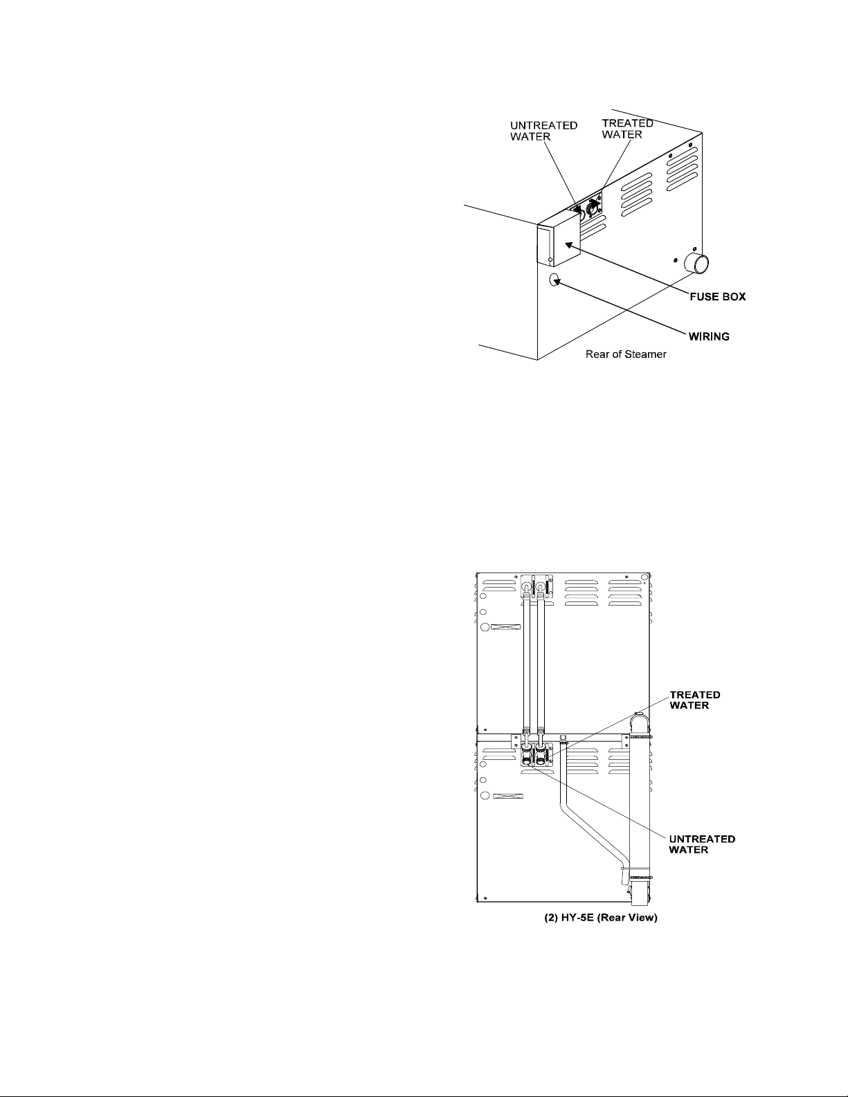
From t he rear HY-3E and HY-5E units are
distinguished by the addition of a fuse box, whi c h
lets operators change fuses without removing
panels.
The drain system on all models includes a spray
condenser, which helps keep steam from escaping
from the chamber and cools drain water.
Inspection and Unpacking
The Steamer will be delivered completely
assembled in a heavy shipping car ton strapped to a
skid. On receipt, inspect carton carefully for exterior
damage.
CAUTION
SHIPPING STRAPS ARE UNDER TENSION AND
CAN SNAP BACK WHEN CUT.
Caref ul ly cut the straps and detach the si des of the
car t o n f r om the ski d. P ull t he cart on up of f t he un i t .
Be careful to avoid personal injury or equipment
damage from staples which might be left in the carton
walls.
The HY-5E holds up to five pans.
CAUTION
THE HY-5E WEIGHS 230 POUNDS (104 KG).
THE THE HY-3E WEIGHS 180 POUNDS (82 KG).
YOU SHOULD GET HELP AS NEEDED TO LIFT
THIS WEIGHT SAFELY.
Wr ite down the model number, serial number and
installation date. Keep this information for reference.
Space for these entries is provided at the top of the
Serv ice Log in the back of this manual.
When starting instal lation, chec k pac k ing materi als
to make sure loose parts such as the condensate
drip tray ar e not discarded with thi s material.
4
Page 5
Water Conditioning
It is essential to supply the steam generator with water
that will not form scale. Even though the steam
generator is engi neer ed to minimize scale formation,
scale dev elopment depends on the hardness of y our
water and the number of hours per day you operate
the equipm ent.
Most water supplies are full of minerals which form
scale. It is this scale which could lead to an early
component failure.
Your water utility can tell you about the minerals in
your water. The water going to the steam generator
should have more than 10 to 30 part s per million
(ppm) t otal dissolved solids (TDS) and should have a
pH (acidity rating) of 7.0 or higher. Please follow
these simpl e pr ec autions:
1. The best way to prevent scal e is to use a Groen
PureSteem™ Wat er Treatment S y stem which has
been specifically designed for Groen steamers
and combination ov ens. Do not rely on
unproven water treatment systems sold for
scale prevention and rem oval. They are not
specifically designed to work with Groen
steamers and combination ovens.
Models built sin ce 1998 have a fuse box
mounted on the rear.
On both the HY-3E and HY -5E, the dual water
connections are side by si de on the rear of the unit.
When seen from from the back of the unit, the
treated (softened) water intake is on the right.
2. A well-maint ained water treatm ent system and a
regular cartridge replacement schedule is
essential.
3. Using a Groen PureSteem™ Water Treatment
System will provide longer steam generator/boiler
life, higher steam capacity, and reduce
maint enanc e requirements.
4. If you notic e a sl owdown in steam production or
an increase in deliming, have the steamer
checked for scale build-up. This could be an
indicat ion that the water tr eatment cart r idges need
replacing. Heavy scal e r educ es the unit’s ability to
boil water, and c an even cause component failur e.
MINIMIZE SCALE PROBLEMS BY USING AND
MAINTAINING A SOFTENER AND BY CLEANING
(DELIMING) THE STEAMER REGULARLY.
The optional second water connection can
reduce treated water requirements.
5
Page 6
Installation and Start-Up
WARNING
THE UNIT MUST BE INSTALLED BY PERSONNEL WHO ARE QUALIFIED TO WORK WITH ELECTRICITY
AND PLUMBING. IMPROPE R INSTALLATION CAN CAUSE INJURY T O PERSONNEL AND/OR DAMAGE
TO THE EQUIPME NT. THE UNIT MUST BE INSTALLE D IN ACCORDANCE WITH APPLICABLE CODES
CAUTION
DO NOT INSTALL THE UNIT WITH THE RIGHT OR LEFT SIDE VENTS BLOCKED OR WITHIN 12 INCHES
OF A HEAT SOURCE (SUCH AS A BRAISING PAN, DEEP FAT FRYER, CHARBROILER OR KETTLE).
TO AVOID DRAINAGE PROBLEMS, LEVEL THE UNIT FRONT TO BACK.
1. Electrical Supply Connection
.
A. Panel Removal
Open the wiri ng and c ontrol panel by removing
screws from the r ight side panel. S lide the
panel for ward, and set it aside.
B. Supply Vol tage
The unit must be operated at the rated
nameplat e volt age.
C. Phase Select ion
Refer to st eamer schemati c s (P ages 20-21) for
wiring information.
CAUTION
EACH UNIT MUST HAVE A SEPARATE
GROUND WIRE FOR SAFE OPERATIO N.
D. Terminal Bloc k
The terminal block for incoming power is
located at the back of the c ontrol compar tment.
The ground terminal is l oc ated in the wiring
compart ment near the terminal block.
E. Supply Wire
To determine the type of wire you need for the
power supply, find the operating voltage and
number of phases on the unit data plat e. Refer
to the tabl e below or to the label on the unit’s
back for correct wire size and t emperature
rating. The equipment gr ounding wire must
comply wi th the National E lectrical Code (NEC)
requirements. The schematic on the inside of
the unit’s right side cov er gives dir ec tions for
proper connection of the terminal bl ock jumpers.
The specified wire must be used, or the unit will
not meet Under writers Laboratories and NEC
requirements. The knockout hole is sized for a
¾ inch condui t fit ting on the HY-3E and for a
one inch conduit fit ting on the HY-5E.
WARNING
TO AVO ID DAMAGE OR PERSO NAL INJURY,
FOLLOW THE ELECTRICAL SCHEMATIC
EXACTLY WHEN CO NNE CTING THE UNIT..
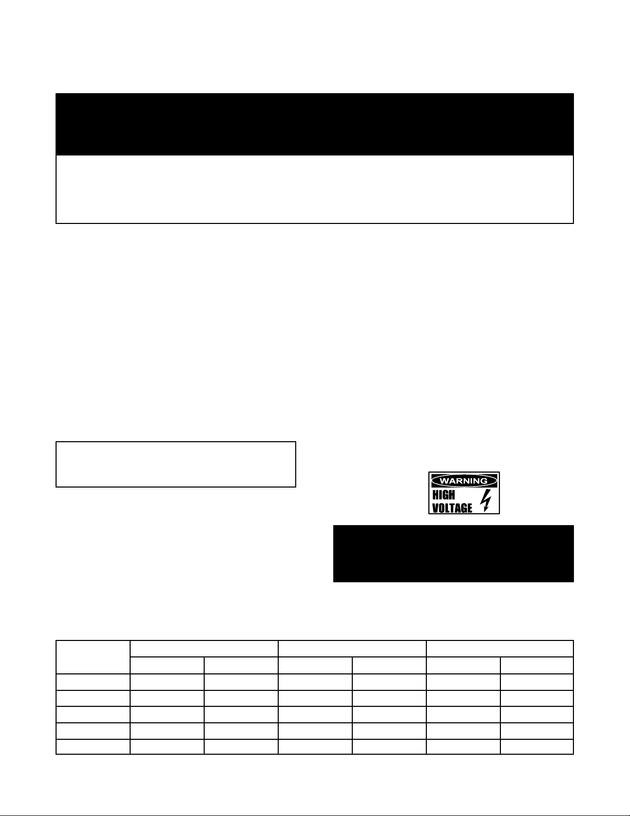
ELECTRICAL SUPPLY CONNECTIONS
FIELD WIRING TABLE - USE COPPER WIRE ONLY - INSULATION RATING THHN (90ºC)
VOLTAGE
(60 Hz Only)
480 3 PHASE 8.1 15.5 14 AWG 12 AW G 10 Amps 18.6 Amps
240 1 PHASE 8.1 15.5 8 AW G 4 AW G 33 A mps 64.6 Amps
240 3 PHASE 8.1 15.5 10 AWG 8 AWG 20 Amps 37.3 Am ps
208 1 PHASE 8.1 15.5 8 AW G 4 AW G 39 A mps 74.5 Amps
208 3 PHASE 8.1 15.5 10 AWG 6 AWG 23 Amps 43.0 Am ps
HY-3E HY-5E HY-3E HY-5E HY-3E HY-5E
KW FIELD WIRING RATED CURRENT DE M AND
6
Page 7

Branch Circ uit Protection
Each Steamer, including individual units of
stacked models, should have its own branch
circuit protection and ground wire. Current
and power demands for each unit are as shown
on Page six.
IMPORTANT: Do not allow water traps in the
line. A trap can cause pressure bu ild-up i n the
cavity, which may cause the door gasket to leak.
4. Factory Stacked Units
2. Water Connection(s)
Install a c hec k valve to prevent back f low in the
incoming cold water line, as required by loc al
plumbing codes. Water pressure in the li ne
should be between 30 and 60 PSIG and must
deliver a flow rate of 1.5 to 3.0 gallons per
minut e. If pressure is above 60 PSIG, a
pressure regulator will be needed.
A ¾ inch female NH connec tor (garden hose
type) is used to attach the water supply to the
inlet valve. Minimum insi de diameter of the
water feed line is ½ inch. Use a washer in the
hose connection. Do not allow the connection to
leak, no matter how slowly. The dual water
standard connecti on, treated (soft ened) water
goes to the right ( seen from the rear of the unit ) ,
and untreated water to the left. Connections for
both are made as shown on Page Five.
3. Drain Connection
Level the steamer front to back, or pitch it
slightly to the rear (maximum ¼ inch) by
adjusting t he bullet f eet on the stand or cabinet
base.
A 2 inch [HY-5E] or 1½ inch [HY-3E] ID hose
may be att ached to the drain pi pe ( suppl ied).
WARNING:
DO NOT CONNECT T HE DRAIN DI RECT L Y T O
A BUILDING DRAIN. BLOCKING THE DRAIN IS
HAZARDOUS.
This section is applicable only if you are installing
factor y-stacked units. If you plan to stac k steamers
yourself , whether purchasing a new one for stacking
or a kit to stack two units you already own, you will
require O M-HY-3E(S), RET ROFIT SUPPLEMENT
(Part Number 121014). These instructions are also
valid for stac k ing HY-5E steamers.
Install ing stacked steamers is similar to installi ng a
single unit. The steamers are stack ed and
assembled at the factory and del ivered with the
water connections and drain hoses required for a
single point connection.
A. Water Connection
At the water inlet valve a ¾ inch female NH
connector (garden hose ty pe) is used for the
water supply. The dual water connection has
two connections to be made. Treated water
(softened) is connected to the ri ght val ve fitting
(looking from t he r ear of the unit) and untreated
water to the left fitting.
B. Electr ical Supply Connec tion
Separate, i ndividual electrical connections
will be required for each steamer in the
stack. Each St eamer must have its own
branch circuit protection.
C. Drain Connection
Steamers must be lev eled front t o back, or
pitched to the rear (maximum ¼ inch) by
adjusting t he bullet f eet on the cabinet or stand
base.
There must be a free air gap between the end of
the hose and the buil ding drain. The free air
gap should be as close as possible to the uni t
drain. T her e must also be no other elbows or
other restri c tions between the unit drain and the
free ai r gap.
CAUTION
DO NOT USE PLASTIC PIPE. DRA IN MUST BE
RATED FOR BO ILING WATER.
Install the drain line with a constant downward pitch.
For HY-3E a 1½ inch and for HY-5E a 2 inch ID
hose may be attac hed to the unit drai n. It must
be rated for boiling water.
7
Page 8
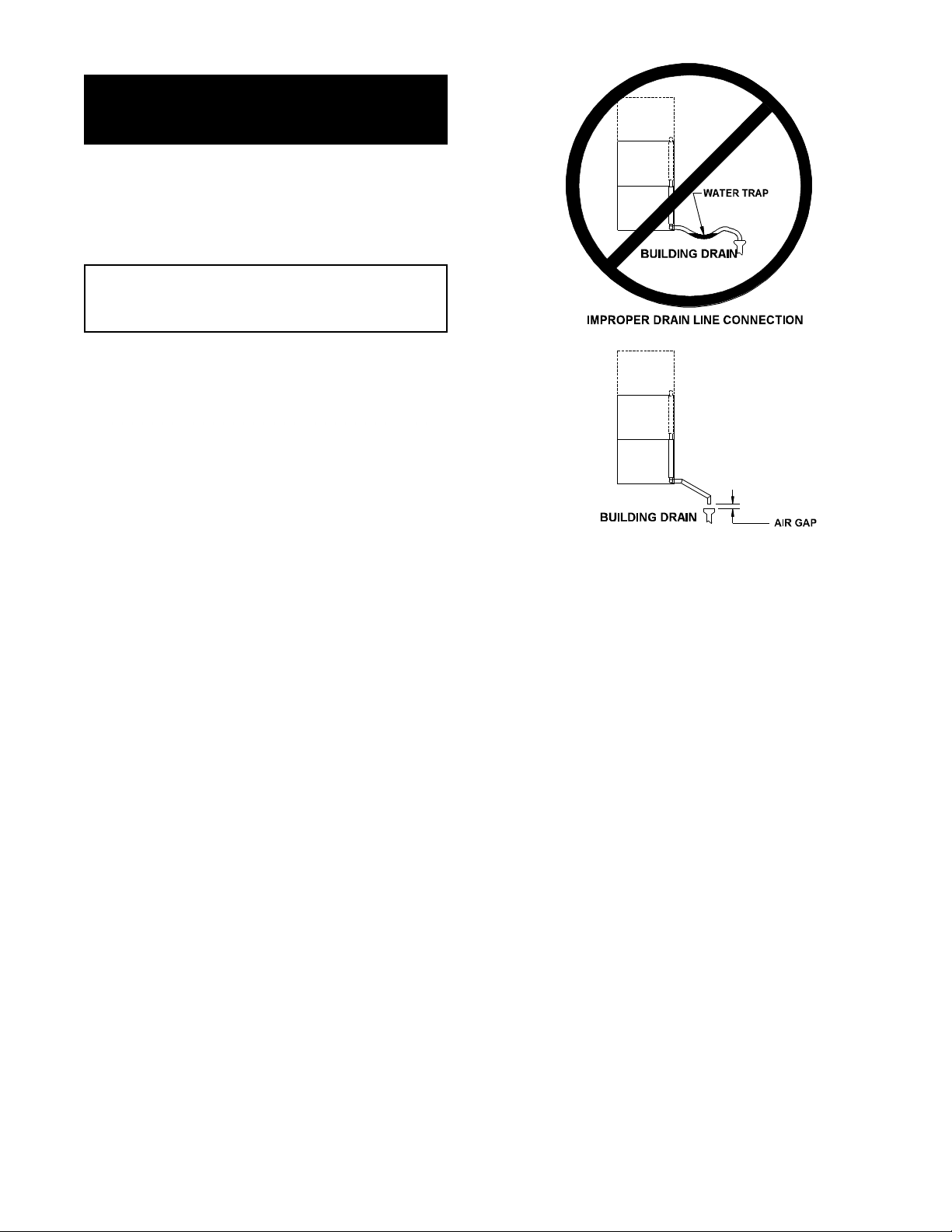
WARNING
DO NOT CONNECT THE UNIT DRAIN DIRECTLY
TO THE BUILDING DRAIN.
Ensure that there is a free air gap bet ween the end
of the unit drain and the building drain. This gap
should be as close as possible to the uni t drain. Do
not allow el bows or restri c tions between the unit and
the free air gap.
CAUTION
DO NOT USE PLASTIC PIPE. DRA IN MUST BE
RATED FOR BO ILING WATER.
Install the line with a constant downward pit c h.
Rear view of (2) HY-5E — Note: Some drain parts
(elbow, clamps) for single mod els are packed inside
the steamer cavity
assembled. Installati on is the same fo r st acked HY-
5E and HY-3E units.
Rear view of (2) HY-5E — Note: Some drain parts
(elbow, clamps) for single mod els are packed inside
the steamer cavity
assembled. Installati on is the same fo r st acked HY5E and HY-3E units.
. Stacked un its are factory-
. Stacked un its are factory-
Proper Drain Line Connection — Drain Line
must have a constant downward pitch of at
least ¼” per f oot. (3)HY-3E shown. Connection
is 1½” for HY-3E, 2" for HY-5E.
8
Page 9

Operation
WARNING
ANY POTENTIAL USER OF THE EQUIPMENT MUST BE TRAINED IN SAFE AND CORR ECT OPERATING
PROCEDURES.
A. Controls
Operator controls are on the fr ont right of the unit.
The HY-5E and HY-3E c ontrol panels have the
following touch pads and indicator lights:
1 The ON/ OFF touch pad gets the HyP er S team
ready for use, or shuts i t off.
2 The READY indicator l ight shows that the steam
generator is at standby temperature and the
cavity is hot enough to begin steaming.
3 When one probe is cov er ed with lim e scale or
fails, the DELIME light flashes briefly every few
seconds, but the unit will continue to operate.
De-lime the unit as soon as possible. The
DELIME light will flash until power is removed
from the unit, or the unit goes through a cl ean
cycle.
4 If the problem continues, both probes may fail.
Then the steam er stops working, and the
SERVICE light is lit. If DELIMING/CLEANING
does no t correct, turn of f the power an d
contact an Authorized Groen Service
Representati ve f or repair.
5 The DELIM E indicator l ight is lit when the unit is
operating in the cleaning mode.
6 The HI TEMP indicat or light com es on when the
steam generator is too hot.
The unit will aut om atically shut off, and cannot
be turned on again until the steam generator
cools and the HI TEMP indic ator light goes out.
8 The TIMING indic ator light stay s on when the
tim er is running.
9 The CLEAN t ouc h pad is used to start the
automatic 50 minute cleaning cycle.
Done Light
Steamer Lig ht
Ready
Indicator
Light
Delime
Indicator
Light Clean Cycle
High Temp
Indicator
Light
Manual ON
Light
Timing
Indicator
Light
ON/OFF
Touch Pad
Power
Indicator
Light
Service
Indicator
Light
Touch Pad
9
Page 10

The timer is used in three ways:
1 In the OFF position the steam generator
stays at a low boil or “ holding” temperature.
2 When a cook time is set, the unit steams
until the timer r uns down to OF F. At that
tim e st eaming stops, a red light comes on
and a beeper sounds.
3 With the t imer turned t o the ON position, the
unit steams continuously. The gr een light
stays lit. The steamer will not time down.
B. Operating Procedure
1. Press the ON/OFF touc h pad for the steamer .
The steam generator will fill, and heat until t he
READY li ght comes on. (About 10 minutes.)
2. Load food into pans in uni form l ay ers. Pans
should be filled to about the same levels, and
should be even on top.
3. Open the door and slide the pans onto the
supports. If y ou will only be steaming one pan,
put it in the middle position.
! If you want to steam continuously, tur n the
tim er to the manual ON position. A gr een
light will come on. The unit will continue
steaming until you stop it by turning the
tim er to OFF. When steaming continuously
YOU MUST CONTROL STEAMING TIME.
WARNING
WHEN YOU OPEN THE DOOR, STAY AWAY
FROM THE STEAM COMING OUT OF THE UNIT.
THE STEAM CAN CAUSE BURNS.
5. Open the door. Remove the pans from the
steamer, usi ng hot pads or oven mitts to protect
your hands from the hot pans.
6. To shut down the unit, press the ON/O FF touch
pad to OFF . The steam generator will
automatically dr ain.
4. Close the door. W ith the READY i ndicator lit,
take one of the following steps:
! If you want to steam t he food for a cer tain
length of time, set the tim er for that period.
The timer will automatically run the steamer
for the set time and then t ur n it off. A red
light will come on and a beeper will sound.
Steam production stops.
10
Page 11

Cleaning
To keep your HY-3E or HY - 5E S teamer in proper working condition, use t he following proc edur e to clean the
unit. T his regular cleaning will reduce the effort required to clean the steam generator and c avit y .
A. Suggested Tools
1. Mild detergent
2. Stainless steel ext er ior cleaner such as
Zepper®
3. Steam generator de-limi ng agent, such as
Groen Delimer Descaler (Part Number
114800), Li me-Away® or an equivalent. A
liqui d de-liming agent will be easier to use than
crystals or powders. Do NOT use any product
containing chlorides or sul f mic acid,
including hydrochloric acid.
4. Groen Spray De-Greaser (Part Number
140830WS)
5. Cloth or sponge
6. Plastic wool or a brush with sof t bristles
7. Spray bottle
8. Measuring cup
9. Nylon pad
10. Towels
11. Plasti c disposable gloves
12. Funnel
B. Procedure
1. Exterior Cleanin g
a. Prepare a warm solution of the mi ld detergent
as instructed by t he suppl ier. Wet a cloth wit h
this solution and wring it out. Use the moist
cloth to clean the outside of the unit. Do not
allow freely running l iquid to touch the
controls, the control panel, any electrical part,
or any louver on the side or rear panels.
b. To remov e material whi c h may be stuck to the
unit, use pl astic wool, a fiber brush, or a plastic
or rubber scraper with a det er gent solution.
c. Stainless steel surfaces may be polished with a
recognized stainless steel cleaner such as
Zepper®.
WARNING
DISCONNECT THE POWER SUPPLY
BEFORE CLE ANING THE OUTSIDE O F
THE STEAMER.
KEEP WATER AND CLEANING
SOLUTIONS OUT OF CONTROLS AND
ELECTRICAL COMPONENTS. NEVER
HOSE OR STEAM CLEAN ANY PA RT OF
THE UNIT.
DON’T MIX DE-LIMING AGENTS (ACID)
WITH DE-GREASERS (ALKALI)
ANYWHERE IN THE UNI T.
AVOID CONTACT WITH ANY
CLEAN ERS, DE-LIMIN G AGENT OR DE GREASER AS RECOMMENDED BY THE
SUPPLIER. MANY ARE HARMFUL.
READ THE WARNINGS AND F OLLOW
THE DIRE CTIONS!
EVEN WHEN THE UNIT HAS BEEN
SHUT OFF, DON’T PUT HANDS OR
TOOLS INTO THE COOKING CHA MBER
UNTIL THE FAN HAS STOPPED
TURNING.
DON’T OPERATE THE UNIT UNLESS
THE REMOVABLE PARTITION HAS
BEEN PUT BACK IN ITS PROPER
LOCATION.
DON’T USE ANY CLEANING OR DELI MI NG AG EN T T HAT C ON TAI NS ANY
SULFAMIC AGENT OR A NY CHLORIDE,
INCLUDING HYDROCHLORIC ACID
(HCl). TO CHECK FOR CHLORIDE
CONTENT SEE ANY MATERIAL
SAFETY DATA SHEETS PROVIDED BY
THE CLEANING AGENT
MANUFACTURER.
IMPORTANT
DO NOT USE ANY METAL MATERIAL (SUCH AS METAL SPONGES) OR METAL IMPLEMENTS (SUCH AS
A SPOON, SCRAPER OR WIRE BRUSH) THAT MIG HT SCRATCH ANY STAINLESS STEEL SURFACE.
SCRATCHES MAKE THE SURFACE HARD TO CLEAN AND PROVIDE PLACES FOR BACTERIA TO GROW.
DO NO T US E STEEL WOOL, WHICH MAY LEAVE PARTICLES IMBEDDED IN THE SURFACE WHICH
COULD EVENTUALLY CAUSE CORROSION AND PITTING.
11
Page 12

2. Steam Generator and Cooking Chamber
Regular deliming, depending on your steamer usage
and local water quality, must be done to enhance
performance and prolong the life of your
HyPerSteam™ convec tion steamer. S teamer must
be turned off aft er every use to prevent lime scale
buildup - do not run steamer conti nuousl y .
ALWAYS USE HOT PADS OR MITTS WHEN
HANDLING HOT STEAMER PANELS OR RACKS.
RECOMMENDED TOOLS & CL E ANERS
- Groen Delimer/Descaler ( Part Number 114800).
Do NOT use any product containing chlorides or
sulfamic acid, including hydrochloric acid .
- Nylon scrub pad, c loth and/or sponge
DELIMING STEPS HY-3E/5E (Use Touch Pad):
STEP 1 - Pr ess ON/OFF to turn steamer off. Open
door.
STEP 2 - Let cavity cool for 5 minutes or longer.
While cool, wipe out cavi ty. Close door.
STEP 3 - Pr ess and hold CLEA N while also turning
steamer on by pressing ON/OFF, until
only DELIME and POWE R lights remain
on (all lights will turn on, then off, except
DELIME and POWER).
:
STEP 6- Delime cycle will start, taking about 30
minut es. When deli me cycle is complete,
DELIME light will appear, DONE l ight will
flash and beeper will beep.
STEP 7- Press ON/OFF to turn steamer off. Let
cavity cool for 5 minutes or longer. Open
door, wipe out i nsi de of cav ity and wipe
door gasket. Close door.
STEP 8- T o use steamer, press ON/OFF . When
READY li ght appears, steamer is ready to
use.
NOTES:
- If DE LIME light flashes rapidly (5 times per
second), press CLEAN to restart delime cycle.
- If power out age oc c ur s during delim ing, delime
cycle must be restarted. Press CLEAN.
- For best performance, do not interrupt del ime
cycle. If delime cycle must be stopped, press
ON/OFF to turn on. Set timer for 5 minutes. After
beeper beeps, press ON/OFF to turn off. Let cavity
cool for 5 minutes or longer, careful ly open
door(s) and wipe out cavity completely .
STEP 4- After 5 minutes, beeper will beep rapidly,
signaling y ou to add Groen Delimer/
Descaler. Door(s) must remain closed for
entire delime cycle.
STEP 5- Pour 1 pint (2 cups) of delimer PE R
CAVITY into upper and /or lower del iming
port(s) and then close port(s). Press
CLEAN. Double-stacked unit cavities
may be delimed together or seperately.
Deliming
Port
12
Page 13

Maintenance
The HY-3E and HY-5E S teamers are designed for
minimum maintenance, and no user adj ust ments
should be necessary. Certai n par ts may need
replacement after pr olonged use. If t her e is a need
for service, only authorized Groen Service
Representatives should perform the work.
Always supply water with a l ow m ineral count t hat
meets the standards outlined in the Water
Conditioning section of this manual.
If steam or condensate is seen leaking from around
the door, tak e the foll owing steps:
1. Check t he door gasket . Replace it if it is cracked
or split.
2. Inspect the cooking chamber dr ain to be sure it
is not block ed.
3. Adjust the door latch pin to allow for c hanges
that might occur as the gasket ages.
a. Loosen the loc k nut at the base of the latch
pin, then t urn the latch pi n ¼ turn clockwise,
and tighten t he lock nut.
b. After adjustm ent, run the unit to test for
further steam leakage.
c. If there is still leakage, repeat the
adjustment.
d. Conti nue adjusting the pin c lockwise until
the door fits tightly enough to prev ent
leakage.
Troubleshooting
This Groen Steamer is designed to operate smoothly and effic iently i f properly maintained. However, the
following is a list of checks to mak e in the event of a problem. Wiring diagr ams are furni shed i nsi de the servic e
panel. If an item on the check li st is marked with (x), it means that the work should be done by a factoryauthorized service representativ e.
SYMPTOM WHO WHAT TO CHECK
Steam generator does not
fill with water.
No steam. User a. Is the O N switc h depr essed?
DELIME light comes on
after four minutes.
Excessive steam escaping
from rear of uni t
User a. Is the O N switc h depr essed?
b. Is the water supply c onnec ted?
c. Is the water turned on?
d. Check for low water pressure (less than 30 PSI) or low
water fl ow (l ess than 1.5 gpm).
e. Is the screen at the water connection clogged?
f. Has the steam gener ator been de-limed?
b. Is the water supply c onnec ted?
c. Is the water turned on?
d. Are steamer doors complet ely closed?
e. Is the steam generator blocked wi th lime build-up?
User a. Is the water supply c onnec ted and adequate?
b. Is the water t ur ned on?
c. Has the unit been de-limed? (Refer to Cleaning Section)
User a. Is the water spray hose ki nk ed or obstructed?
Auth Service
Rep Only
b. Is the water spray solenoid connected?(x )
c. Is the drain pr oper ly vented? (x)
13
Page 14

Parts List - HY-3E
To order parts, contact your authorized Groen Service Agency. Supply the model designation, serial number, part
description, part number, quantity, and when applicabl e, vol t age and phase.
REAR VIEW
Key Description Part # Key Descrip t ion Part #
1 Right Side Panel 123134 15 Top Panel ( S ingle) 142428
2 Door Assy, Complete 130858 Top Panel (Double) 142443
3 Door Handl e 129723 16 Cov er , Fuse Box 119846
4 Door Gasket 124849 17 Back Panel 123114
5 Left pan Rack 094148 18 Optional Table 100913
6 Bl ower Cover/Rack (fan baffle) 096788 19 Dri p Tray 094151
7 Door Latc h P in 078914 20 T imer Fastener Nut 101145
8 Door Pin Lock Nut 003823 21 Drain Tube 123115
9 Left Side Panel 123135 22 Water Valve Dual Water Supply 100934
10 Cavity Fan 096790 x Mot or S haft Seal 096868
11 Door Switch 096857 x Heat S hield 118127
12 Tim er 096826 x S ingle Water Adaptor 108702
13 Tim er Knob 123100 x Optional Legs 041121
14 Front Panel Overlay 123126 x PC Boar d Cover 119806
x G roen De-lim er /De-scaler 114800
x - It em not depict ed/called out in drawing or photographs
14
Page 15

Parts List - HY-3E
To order parts, c ontact your authorized Groen Service Agency. S upply the model desi gnation, serial number, part description, part number, quantity, and
when applicable, voltage and phase.
15
Page 16

Parts List - HY-3E
To order parts, c ontact your authorized Groen Service Agency. S upply the model desi gnation, serial number, part description, part number, quantity, and
when applicable, voltage and phase.
Key Description Part Key Description Part Key Description Part
1 Platform Assembly 142416 10 Val ve Water Inlet Assy Dual Supply 088816 35 Contact or 119811
2 Fan Motor Assembly 096740 11 Timer, St eamer, 60 Hz 096826 x Toroid Transf or mer 480/230 V 119856
x Chassis Assembly, E lectrical 142426 12 Knob, Timer 123100 37 Transfor mer 20 V AC CT 119815
4 Fuse Block Assembly 119848 13 Steamer Control PC Board 141082 x Relay, 12 V DC 119813
x Fuse Holder 096809 14 Light & Tim er P C B oar d 137233 x Terminal Block 119850
x Fuse, 6 Amp 119823 x Standoff , Hex M-F 6-32 x ¾ 119826 x 2 Amp Circuit B r eak er 119836
5 Cover, Fuse Box 119846 16 Standoff, Hex M-F 6-32 x 1¼ 119827 42 Door Switch 096857
6 Heater Elem Assy w/Tstat 208V 141846 x Harness, Timer Motor 123120 43 S team Port 142413
6 Heater Elem Assy w/Tstat 240V 142146 x Jumper, Ctrl Bd to Display Bd 123122 x S team Port Gasket 099250
6 Heater Elem Assy w/Tstat 480V 142148 x Cover, Cont r ol Panel 119806 45 Motor Capacitor 096813
6 Heater Elem Assy w/Tstat 200V 142151 x Nut, Keps, 6-32 071289 x Water Fill Hose 125993
6a Heater Elem A ssy w/o Tstat 208V 141183 x Nut, Keps 10-32 071256 x St eam Generator wit h Insulation, 142417
6a Heater Elem A ssy w/o Tstat 240V 141184 x Nut, Lock Nylon Insert 6-32 119855 Probes, Reli ef Valve & Fittings
6a Heater Elem A ssy w/o Tstat 480V 141185 x Screw, Rd Hd Self-tapping 6-32x
6a Heater Elem A ssy w/o Tstat 200V 141186 x Screw Slot Hex Washer 8-32 x ¼ 074242 x Condensate Spray Hose 125994
6b Heater Element Gasket 042366 x Screw Slot Hex Washer 8-32 x ½ 009696 x Water Fl ow Reducer 088877
7 Li ne Connec tion Assembly 128395 26 Phase, Wire for Terminal Block 094155 51 A daptor, Delime, Top 142431
8 Ready Thermostat 088865 x Nut, Rotary Shaft Seal (T imer) 101145 52 Cap, Delime top, HY - 3E 142432
9 Water Level Probe- Right (Short) 141285 x Plug, Pipe ¼ NPT 304 SS 004145 x Adapt er , 3/4" MGHT t o 1/2" MPT 142433
Water Level Probe- Left ( Long) 141424 x Hose 1½ ID x 20" 088846 x Washer, Hose, 3/4" 122143
x Hi Limit Thermostat 094161 31 Clamp, Constant T ensi on 1¾ ” 126011 x Washer, .875 I.D. x .125 THK 142297
x Thermostat Clam p 093482 34 Transformer 208/240 V 106234
d 012398 x M otor Shaft S eal 096868
x - It em not depict ed/called out in drawing or photographs
16
Page 17

Parts List - HY-5E
To order parts, c ontact your authorized Groen Service Agency. S upply the model desi gnation, serial number,
part descript ion, part number , quantity, and when applicable, voltage and phase.
Key Descriptio n Part No. Key Description Part No.
1 Left Pan Rack 125901 12 Door Pin Lock Nut 003823
2 Door A ssembly, Compl ete 125922 13 Front Panel Overlay 123127
3 Door Gasket 125907 14 Water Valve, S ingle Supply 071235
4 Door Handle 129723 15 B ac k P anel 125932
5 Drip Tray 094151 16 Left Side Panel 125931
6 Top P anel (Single) 142443 17 Drai n Tube 125918
Top Panel (Double) 142428 x Drain Valve 071234
7 Blower Cover/Right Pan Rack 125902 x Drain Val ve Bracket 099991
8 Timer 096826 x Drain Hose, Steam Generator 125998
9 Timer Knob 123100 x Drain Kit 120699
10 Right Side Panel 125930 x Water V alve, Dual Supply 100934
11 Door Latch Pin 078914 x G r oen De- limer - De- scaler 114800
x - It em not depict ed/called out in drawing or photographs
17
Page 18

Parts List - HY-5E
To order parts, c ontact your authorized Groen Service Agency. S upply the model desi gnation, serial number, part description, part number, quantity, and when
applicable, voltage and phase.
18
Page 19

Parts List - HY-5E
To order parts, c ontact your authorized Groen Service Agency. S upply the model desi gnation, serial number, part description, part number, quantity, and when
applicable, voltage and phase.
Key Description Part Key Description Part Key Description Part
1 Platform Assembly 142135 12a Timer, S teamer, 60 Hz 096826 34 Transfor mer 208/240 V 106234
2 Fan M otor Assembly 096740 x Knob, Timer 123100 35 High Heat Contactor 119811
x Chassis Assembly, E lectrical 142426 13 Steamer Control PC Board 137233 x Toroid Transformer 480/230 V 119856
4 Fuse Block Assembly 119848 14 Li ght & Timer P C B oar d 119817 37 Transformer 20 V A C CT 119815
x Fuse Holder 096809 x Standoff, Hex M- F 6-32 x ¾ 119826 x Relay, 12 V DC 119813
x Fuse, 6 Amp 119823 x Standoff, Hex M- F 6-32 x 1¼ 119827 40 Terminal Block 119850
x Cover, Fuse Box 119846 x Harness, Timer Motor 123120 x 2 Amp Circuit Breaker 119836
6 Heater Elem Assy w/Tstat 208V 141846 x Jumper, Ct r l Bd to Display B d 123122 42 Door Switch 096857
6 Heater Elem Assy w/Tstat 240V 142146 x Cover, Control Panel 119806 43 Steam Port 142413
6 Heater Elem Assy w/Tstat 480V 142148 x Nut, Keps, 6-32 071289 x Steam Port Gasket 099250
6 Heater Elem Assy w/Tstat 200V 142151 x Nut, Keps 10-32 071256 45 Motor Capac itor 096813
6a Heater Elem A ssy w/o Tstat 208V 141183 x Nut, Lock Nylon I nsert 6-32 119855 x Water Fill Hose 125993
6a Heater Elem A ssy w/o Tstat 240V 141184 x Screw, Rd Hd Self- tapping 6-32x
6a Heater Elem A ssy w/o Tstat 480V 141185 x S c rew Slot Hex Washer 8-32 x ¼ 074242 Probes, Reli ef Valve & Fittings
6a Heater Elem A ssy w/o Tstat 200V 141186 x Screw Slot Hex Washer 8-32 x ½ 009696 x M otor Shaft S eal 096868
6b Heater Element Gasket 042366 26 Phase, Wire for Term inal Block 094155 x Condensate S pr ay Hose 125994
7 Li ne Connec tion Assembly 128395 x Nut, Rotary S haft Seal (Timer) 101145 x Water F low Reducer 088877
8 Ready Thermostat 088865 x Plug, Pipe ¼ NPT 304 SS 004145
9 Water Level Probe (upper) 141284 30 Hose 1½ ID x 20" 088846
Water Level Probe (lower) 141285 31 Clamp, Constant T ensi on 1¾ ” 126011
Valve Water Inlet Assy Dual
10
Supply
088816
d 012398 x S team Generator with Insulation, 142138
x - It em not depict ed/called out in drawing or photographs
19
Page 20

Electrical Schematic - Model HY-3E
20
Page 21

Electrical Schematic - Model HY-5E
21
Page 22

Service Log
Model No.
Serial No.
Date Purchased
Purchase Order No.
Date Maintenance Performed Performed by
Purchased From
Location
Date Installed
For Service Call
22
Page 23

LIMITED WARRANTY TO
COMMERCIAL PURCHASERS*
(U.S.and Canadian Sales Only)
Groen Foodservice Equipment (“Groen E quipment”) has been skillfully manufac tured, carefully inspected, and
packaged to meet rigid standards of excellence. Groen warrants it s equi pment to be f r ee from defects in material
and workmanship for twelve ( 12) months from installation date or fifteen ( 15) months from date of shipment from
Groen, with the foll owing c onditions and subject t o the foll owing limitations:
I. This parts and labor warranty i s limited to Groen Equipment sold to the original commercial
purchaser/users (but not original equipment manufacturers {O.E .M.}), at its original place of installation
in the continental United States, Hawaii and Canada.
II. Damage during shi pment is to be reported to the carri er , is not cov er ed under this warranty, and is t he
sole responsibility of the purchaser/user.
III. Groen, or an authorized service representative, will repair or r eplace, at Groen’s sole discretion, any
Groen equipment, including but not limit ed to, drawoff valves, safety valves, gas and electric
components, found to be defec tive dur ing the warranty period. As to warranty service in the ter r itory
described above, Groen will absorb labor and portal t o por tal transportation costs (time and mileage) for
the first twelv e ( 12) months from date of i nstallation or fif teen (15) months from date of shipment from
Groen.
IV. T his warranty does not cover boiler maintenance, calibration, per iodic adjustments as specified in
operating i nst r uc tions or manuals, and c onsumable parts such as scraper blades, gaskets, packing, etc.,
or labor costs inc ur r ed for removal of adjacent equipment or objects to gain access to Groen
Equipment. This warranty does not cover def ec ts caused by improper i nstallation, abuse, c ar eless
operation, or improper maintenance of equipment. This warranty does not cover damage caused by
poor water quality or improper boiler maintenance.
V. THIS WARRANTY IS EXCLUSIVE AND IS IN LIEU OF ALL OTHER WARRANTIES, EXPRESS OR
IMPLIED, INCLUDING ANY IMPLIED WARRANTY OF MERCHANTABILITY OR FIT NESS F OR A
PARTICULAR PURPOSE, EACH OF WHICH IS HEREBY EXPRESSLY DISCLAIMED. THE
REMEDIES DESCRIBED ABOVE ARE EXCLUSIVE AND IN NO EVENT SHALL GROEN BE LIABLE
FOR SPECIAL, CONSEQUENTIAL OR INCIDENTAL DAMAGES FOR THE BREACH OR DELAY IN
PERFORMANCE OF THIS WARRANTY.
VI. G r oen Equipment is for commercial use onl y . If sold as a component of another ( O.E.M.)
Manufact urer’s equipment, or if used as a consumer product , such Equipment is sold AS IS and without
any warranty.
*(Covers all Foodservice Equipment Ordered after October 1, 1995)
23
Page 24

1055 Mendell Davis Drive
Jackson, MS 39272
Telephone 601 372-3903
Fax 601 373-9587
OM-HY-5E/HY-3E (9/02)
Part Number 141412
 Loading...