

Page 1
?? IMPORTANT INFORMATION IMPORTANT INFORMATION?? KEEP FOR OPERATOR KEEP FOR OPERATOR?? IMPORTANT INFORMATION IMPORTANT INFORMATION??
OPERATOR MANUAL OM-HY-3E
Part Number 121004 DOMESTIC
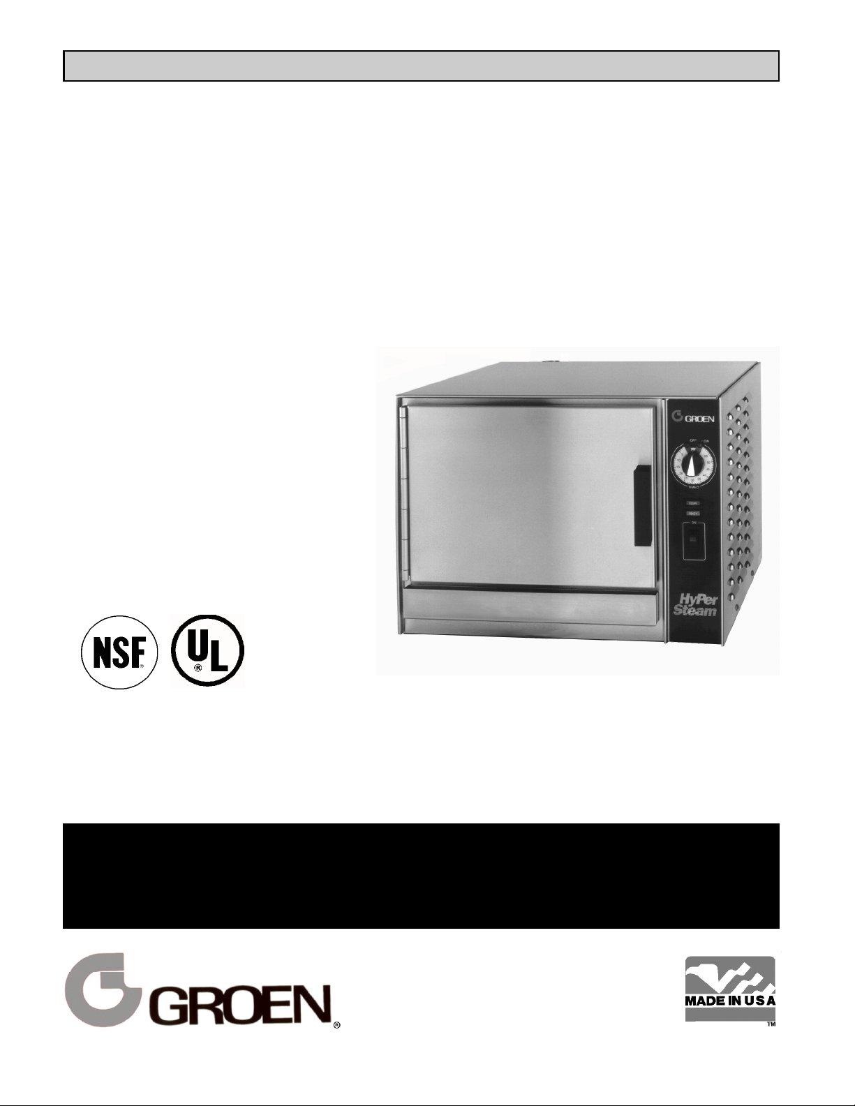
MODEL: HY-3E
HyPerSteam™
Atmospheric Convection
Steamer
Self-Contained
Electric Heated
Capacity: 3 Steamer Pans
(12" x 20" x 2½”)
THIS MANUAL MUST BE RETAINED FOR FUTURE REFERENCE.
READ, UNDERSTAND AND FOLLOW THE INSTRUCTIONS AND
WARNINGS CONTAINED IN THIS MANUAL.
FOR YOUR SAFETY
DO NOT STORE OR USE GASOLINE OR OTHER FLAMMABLE
VAPORS AND LIQUIDS IN THE VICINITY OF THIS OR ANY OTHER
APPLIANCE.
Information contained in this document is
known to be current and accurate at the time
of printing/creation. Unified Brands recommends referencing our product line websites,
unifiedbrands.net, for the most updated
product information and specifications.
Page 2

OM-HY-3E
IMPORTANT — READ FIRST — IMPORTANT
WARNING: THE UNIT MUST BE INSTALLED BY PERSONNEL QUALIFIED TO WORK WITH
ELECTRICITY AND PLUMBING. IMPROPER INSTALLATION CAN CAUSE INJURY TO
PERSONNEL AND/OR DAMAGE TO THE EQUIPMENT. THE UNIT MUST BE INSTALLED IN
ACCORDANCE WITH APPLICABLE CODES.
CAUTION: SHIPPING STRAPS ARE UNDER TENSION AND CAN SNAP BACK WHEN CUT.
CAUTION: DO NOT INSTALL THE UNIT IN ANY WAY WHICH WILL BLOCK THE RIGHT SIDE VENTS,
OR WITHIN 12 INCHES OF A HEAT SOURCE SUCH AS A BRAISING PAN, DEEP FRYER,
CHAR BROILER OR KETTLE.
CAUTION: LEVEL THE UNIT FRONT TO BACK, OR PITCH IT SLIGHTLY TO THE REAR, TO AVOID
DRAINAGE PROBLEMS.
WARNING: TO AVOID DAMAGE OR INJURY, FOLLOW THE WIRING DIAGRAM EXACTLY WHEN
CONNECTING A UNIT.
CAUTION: DO NOT USE PLASTIC PIPE. DRAIN MUST BE RATED FOR BOILING WATER.
WARNING: DO NOT CONNECT THE DRAIN DIRECTLY TO A BUILDING DRAIN.
WARNING: BLOCKING THE DRAIN IS HAZARDOUS.
IMPORTANT: Improper drain connection will void warranty.
IMPORTANT: Do not allow any water traps in the line. A trap can cause pressure to build up inside the
cavity during steaming, which will make the door gasket leak.
WARNING: WHEN YOU OPEN THE DOOR, STAY AWAY FROM STEAM COMING OUT OF THE UNIT.
STEAM CAN CAUSE BURNS.
WARNING: BEFORE CLEANING THE OUTSIDE OF THE STEAMER, DISCONNECT THE ELECTRIC
POWER SUPPLY. KEEP WATER AND CLEANING SOLUTIONS OUT OF CONTROLS AND
ELECTRICAL COMPONENTS. NEVER HOSE OR STEAM CLEAN ANY PART OF THE UNIT.
WARNING: ALLOW COOKING CHAMBER TO COOL BEFORE CLEANING.
WARNING: CAREFULLY READ THE WARNINGS AND FOLLOW THE DIRECTIONS ON THE LABEL OF
EACH CLEANING AGENT. USE SAFETY GLASSES AND RUBBER GLOVES AS
RECOMMENDED BY DELIMING AGENT MANUFACTURER.
WARNING: DO NOT MIX DE-LIMING AGENTS (ACID) AND DE-GREASERS (ALKALI).
WARNING: DO NOT PUT HANDS OR TOOLS INTO THE COOKING CHAMBER UNTIL THE FAN HAS
STOPPED TURNING.
WARNING: DO NOT OPERATE THE UNIT UNLESS THE REMOVABLE RIGHT SIDE PANEL HAS BEEN
RETURNED TO ITS PROPER LOCATION.
NOTICE: DO NOT USE A CLEANING OR DE-LIMING AGENT THAT CONTAINS ANY SULFAMIC ACID
OR ANY CHLORIDE, INCLUDING HYDROCHLORIC ACID. IF THE CHLORIDE CONTENT OF
ANY PRODUCT IS UNCLEAR, CONSULT THE MANUFACTURER.
NOTICE: DO NOT USE ANY DE-GREASER THAT CONTAINS POTASSIUM HYDROXIDE OR SODIUM
HYDROXIDE OR THAT IS ALKALINE.
WARNING: USE OF ANY REPLACEMENT PARTS OTHER THAN THOSE SUPPLIED BY GROEN OR
THEIR AUTHORIZED DISTRIBUTOR VOIDS ALL WARRANTIES AND CAN RESULT IN
BODILY INJURY TO THE OPERATOR AND DAMAGE THE EQUIPMENT. SERVICE BY
OTHER THAN FACTORY-AUTHORIZED PERSONNEL WILL VOID ALL WARRANTIES.
WARNING: HIGH VOLTAGE EXISTS INSIDE CONTROL COMPARTMENTS. DISCONNECT FROM
BRANCH BEFORE SERVICING. FAILURE TO DO SO CAN RESULT IN SERIOUS INJURY
OR DEATH.
2
Page 3

OM-HY-3E
Table of Contents
OPERATOR WARNINGS ................................................................. 2
REFERENCES ......................................................................... 3
EQUIPMENT DESCRIPTION .............................................................. 4
INSPECTION AND UNPACKING ........................................................... 4
WATER CONDITIONING/REQUIREMENTS ................................................... 4
INSTALLATION AND START-UP INSTRUCTIONS .............................................. 5
OPERATING INSTRUCTIONS ............................................................. 8
CLEANING AND MAINTENANCE PROCEDURES
CLEANING ...................................................................... 9
MAINTENANCE AND TROUBLESHOOTING ........................................... 11
PARTS LIST .......................................................................... 12
SCHEMATICS ......................................................................... 15
SERVICE LOG ........................................................................ 17
WARRANTY PROTECTION .............................................................. 19
References
UNDERWRITERS LABORATORIES, INC. NATIONAL FIRE PROTECTION
333 Pfingsten Road ASSOCIATION
Northbrook, Illinois 60062 60 Battery March Park
Quincy, Massachusetts 02269
KLENZADE SALES CENTER NFPA/70 The National Electrical Code
ECOLAB, Inc.
370 Wabasha NATIONAL SANITATION FOUNDATION
St. Paul, Minnesota 55102 3475 Plymouth Road
800 328-3663 or 612 293-2233 Ann Arbor, Michigan 48106
3
Page 4
OM-HY-3E
Equipment Description
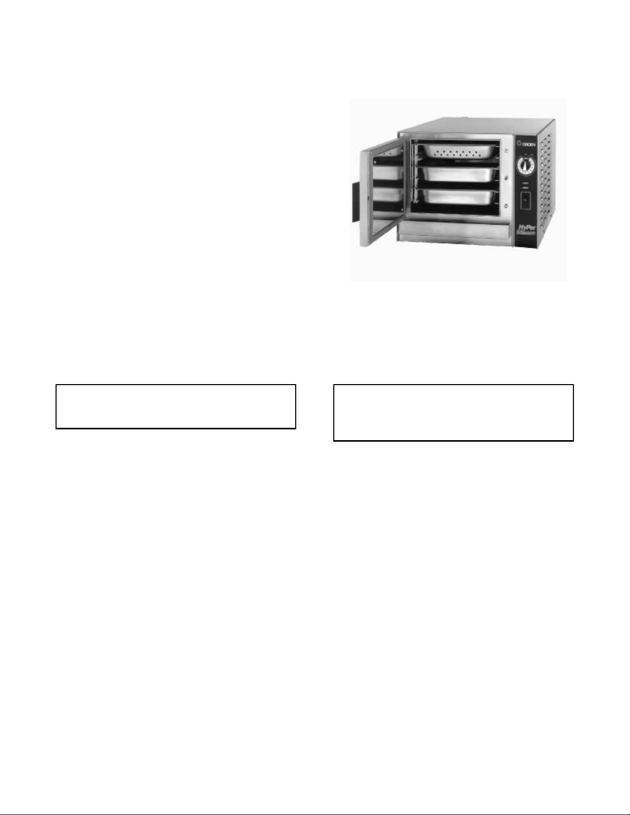
Your Groen HY-3E HyPerSteam Convection
Steamer is designed to give years of service. It has
a stainless steel cavity (cooking chamber) which is
served by an independent atmospheric steam
generator which is electrically-heated. A powerful
blower circulates the steam In the cavity to increase
heating efficiency.
The cavity holds up to three steam table pans (12" x
20" x 2½"). A 16 gauge stainless steel case
encloses the cavity, the steam generator and the
control compartment that houses electrical
components. Door hinges are reversible (the door
may be set to open from the left or right). Operating
Controls are on the front panel.
The drain system includes a spray condenser, which
helps keep steam from escaping from the chamber.
Inspection and Unpacking
The HY-3E steamer holds three standard
12"x 20"x 2-½" pans.
The HY3-E will be delivered completely assembled Write down the model number, serial number and
in a heavy shipping carton attached to a skid. On installation date and keep this information for future
receipt, inspect the carton carefully for exterior reference. Space for these entries is provided at the
damage. top of the Service Log in the back of this manual.
CAUTION CAUTION
SHIPPING STRAPS ARE UNDER TENSION THIS UNIT WEIGHS 180 POUNDS (82 KG).
AND CAN SNAP BACK WHEN CUT. YOU SHOULD GET HELP AS NEEDED TO
LIFT THIS WEIGHT SAFELY.
Carefully cut the straps around the carton and detach
the sides of the carton from the skid. Pull the carton
up off the unit. Be careful to avoid personal injury or
equipment damage from staples which might be left in
the carton walls.
When starting installation, lift the unit straight up off
the skid. Check packing materials to make sure loose
parts are not discarded with the material.
Water Conditioning
It is essential to supply the steam generator with these simple precautions:
water that will not form scale. Even though the
steam generator is engineered to minimize scale
formation, scale development depends on the
hardness of your water and the number of hours you
operate the equipment.
In some areas, water is low enough in mineral
content to avoid scale formation. But most water
supplies are full of minerals which form scale. It is
this scale which could lead to an early component
failure.
Your water utility can tell you about the minerals in
your water. The water going to the steam generator
should have between 10 and 30 parts per million
(ppm) total dissolved solids (TDS) and should have
a pH (acidity rating) of 7.0 or higher. Please follow
1. Do not rely on unproven water treatments
which are sold for scale prevention or scale
removal. They don’t always work. The best
way to prevent scale is to supply the purest
possible water (10 - 20 ppm TDS).
2. If your water contains scale-forming minerals,
as most water does, use a well-maintained
water softener. Whether an exchangeable
softener cartridge or a regenerating system is
chosen, a regular exchange schedule is
essential.
3. Installing a water meter between the softener
and the steamer will provide an accurate gauge
of water use, and will help determine when to
exchange cartridges or regenerate the softener.
4
Page 5
Using a water softener will provide longer
generator life, higher steam capacity, and
reduce maintenance requirements.
4. If you notice a slowdown in steam production,
have the unit checked for scale build-up. Heavy
scale reduces the unit’s ability to boil water, and
can even cause heating elements in the steam
generator to overheat and burn out.
MINIMIZE SCALE PROBLEMS, BY USING AND
MAINTAINING A SOFTENER, AND BY CLEANING
THE STEAMER REGULARLY.
Groen Steamers are also available with an option
for two separate water intakes — one for the steam
generator (soft water), the other for the spray
condenser (untreated water). The steam generator
only uses 14 to 31% of a steamer’s water.
OM-HY-3E
The optional second water connection
can reduce treated water requirements.
Since softener systems are typically sized by total
GPH (gallons per hour), the second intake could
reduce treatment requirements by up to 80%,
resulting in significant savings.
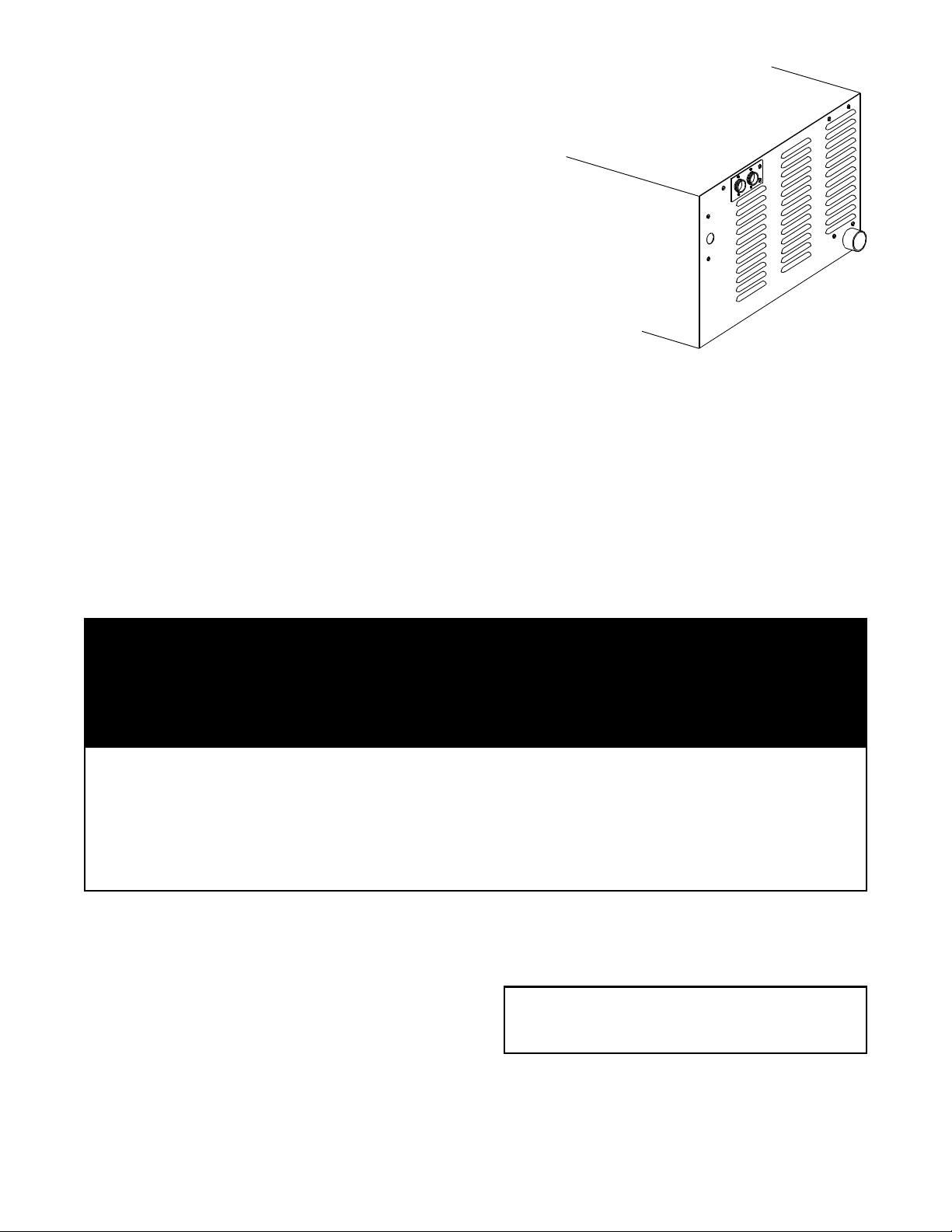
On the HY-3E, the twin water connections are side
by side on the rear of the unit. When facing the back
of the unit, the treated (softened) water intake is on
the right.
Installation and Start-Up
WARNING
THE UNIT MUST BE INSTALLED BY PERSONNEL WHO ARE QUALIFIED TO WORK WITH
ELECTRICITY AND PLUMBING. IMPROPER INSTALLATION CAN CAUSE INJURY TO
PERSONNEL AND/OR DAMAGE TO THE EQUIPMENT. THE UNIT MUST BE INSTALLED
IN ACCORDANCE WITH APPLICABLE CODES.
CAUTION
DO NOT INSTALL THE UNIT WITH THE RIGHT SIDE VENTS BLOCKED OR WITHIN 12
INCHES OF A HEAT SOURCE (SUCH AS A BRAISING PAN, DEEP FRYER, CHAR
BROILER OR KETTLE).
TO AVOID DRAINAGE PROBLEMS, LEVEL THE UNIT FRONT TO BACK.
1. Electrical Supply Connection
A. Panel Removal
Open the wiring and control panel by removing
two screws on the right side panel. Slide the
panel forward, and set it aside.
B. Supply Voltage
Refer to the heater schematic (Pages 15 and
16) for wiring information.
CAUTION
THE UNIT MUST HAVE A SEPARATE
GROUND WIRE FOR SAFE OPERATION.
The unit must be operated at the rated
nameplate voltage, plus or minus 10 percent.
C. Phase Selection
D. Terminal Block
The terminal block for incoming power is
located at the back of the control compartment.
5
Page 6
OM-HY-3E
The ground terminal is located in the wiring The wire specified has to be used, or the unit
compartment above the terminal block.
Minimum size for the ground wire is 10 AWG.
will not meet Underwriters Laboratories and
National Electric Code requirements.
E. Supply wire
To determine the type of wire you need for the
power supply, find the operating voltage and
phase on the unit data plate. Refer to the table
provided on the next page or to the label on the
unit’s back for the correct wire size and
insulation temperature rating. The “Electrical
Supply Connection” label on back right side of
the unit gives directions for proper connection of
the terminal block jumpers.
The knockout hole is sized for a 3/4 inch conduit
fitting.
WARNING
TO AVOID DAMAGE OR PERSONAL
INJURY, FOLLOW THE ELECTRICAL
SCHEMATIC EXACTLY WHEN
CONNECTING THE UNIT
ELECTRICAL SUPPLY CONNECTIONS
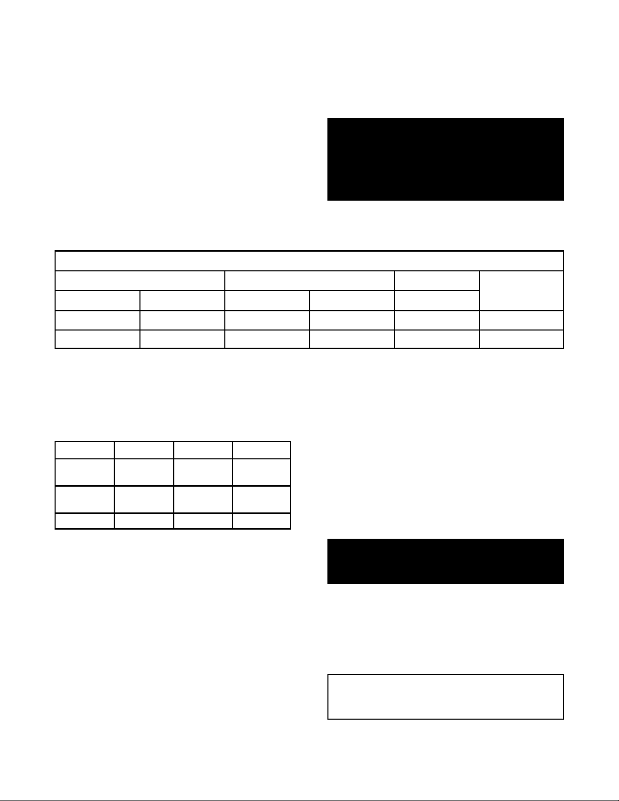
FIELD WIRING TABLE - USE ONLY COPPER WIRE
208 VOLT 240 VOLT 480 VOLT INSULATION
1 PHASE 3 PHASE 1 PHASE 3 PHASE 3 PHASE
6 AWG 10AWG 8 AWG 10 AWG 14 AWG THWN (70 C)
8 AWG 10 AWG 8 AWG 10 AWG 14 AWG THWN (90 C
F. Branch Circuit Protection If you have the twin water connection option, put
the treated water (softened) to the right intake
We strongly recommend that the HY-3E
Steamer have its own branch circuit
protection. Current and power demands for the
different units are as follows:
(facing the rear of the unit), and untreated water
to the left. Connections for both are made as
described above.
RATING
o
o
3. Drain Connection
VOLTAGE PHASE AMPS MAX. KW
208 1 39 8
3 23 8
240 1 33 8
3 20 8
480 3 10 8
The HY-3E Steamer must be leveled front to
back, or even pitched slightly to the rear by
adjustment of the bulllet feet on the cabinet
base.
A 1½ inch (38mm) ID hose may be attached to
the drain pipe (supplied).
2. Water Connection(s)
Install a check valve to prevent back flow in the
incoming cold water line, as required by local
plumbing codes.
Water pressure in the line should be between 30
and 60 PSIG (210 and 420 kPa). If pressure is
above 60 PSIG, a pressure regulator will be
needed.
A ¾ inch R connector (garden hose type) is
used to attach the water supply to the water inlet
valve. The minimum water feed line diameter is
½ inch (13mm). Use a washer in the hose
connection. Do not allow the connection to leak,
no matter how slowly.
WARNING:
DO NOT CONNECT THE DRAIN DIRECTLY TO
A BUILDING DRAIN.
There must be at least one-half inch free air gap
between the end of the hose and the building
drain. The free air gap should be as close as
possible to the unit drain. There must also be
no other elbows or other restrictions between
the unit drain and the two inch free air gap.
CAUTION
DO NOT USE PLASTIC PIPE. DRAIN MUST
BE RATED FOR BOILING WATER.
6
Page 7

WARNING
BLOCKING THE DRAIN IS HAZARDOUS.
Install the drain line with a constant downward
pitch.
DRAIN LINE INSTALLATION
OM-HY-3E
IMPORTANT: Do not allow any water traps in
the line. A trap can cause pressure to build up
inside the cavity during steaming, which will
make the door gasket leak.
(WITH DRAIN BOX)
OPTION ONE: To go OPTION TWO:
from Stainless Steel Elbow (P/N 092272) to nearby
floor drain, you can use “Radiator” Hose (McMasterCarr #5297K24 - at least a 212 F rated hose), and
one additional hose clamp (P/N 073259).
o
(WITHOUT DRAIN BOX)
Using the hose (P/N 073254) and two hose clamps
(P/N 073259), you can connect 1½” copper tubing to
the floor drain. NOTE: All drain line runs must be
pitched downward approximately ½” per foot.
No water traps are allowed in the drain line.
From the Muller Brass coupling-reducer (P/N W-1095), you can connect 1½”“ copper tubing to the floor drain.
7
Page 8

OM-HY-3E
Operation
WARNING
ANY POTENTIAL USER OF THE EQUIPMENT SHOULD BE TRAINED IN SAFE AND
CORRECT OPERATING PROCEDURES.
A. Controls
Operator controls are on the front right of the unit.
The ON switch gets the HyPerSteam ready for use,
or shuts it off. The READY indicator light shows
that the steam generator is at standby temperature,
which means that the cavity is hot enough to begin
cooking.
WHEN YOU OPEN THE DOOR, STAY AWAY
FROM THE STEAM COMING OUT OF THE UNIT.
THE STEAM CAN CAUSE BURNS.
WARNING
The timer is used in three ways:
• In the OFF position the steam generator
stays at a very low boil or “holding”
temperature.
• When a cook time is set, the unit steams
until the timer runs down to OFF. At that
time steaming stops, a red light comes on
and a beeper sounds.
• When turned all the way to the ON position,
the unit steams continuously. The green
light stays lit, and the steamer will not time
down.
B. Operating Procedure
1. Press the ON switch for the steamer. The
steam generator will automatically fill with water,
and heat the water until the READY light comes
on. The indicator should light within 10 minutes.
2. Load food into pans so that it is in uniform
layers. Pans should be filled to about the same
levels, and should be even on top.
3. Open the door and slide the pans onto the
supports. If you will only be steaming one pan,
put it in the middle position.
• If you want to steam continuously, turn the
timer to the manual ON position. A green
light will come on. The unit will continue
steaming until you stop it by turning the
timer to OFF. When steaming continuously
YOU MUST CONTROL STEAMING TIME.
5. Open the door. Remove the pans from the
steamer, using hot pads or oven mitts to protect
your hands from the hot pans.
6. To shut down the unit, press the ON switch to
the OFF position. The steam generator will
automatically drain.
4. Close the door. With the READY indicator lit,
take one of the following steps:
• If you want to steam the food for a certain
length of time, set the timer to that time.
The timer will automatically run the steamer
for the set time and then turn it off. A red
light will come on and a beeper will sound.
Steam stops.
Controls for the HY-3E are simple, and easy
to operate.
8
Page 9

OM-HY-3E
Cleaning
To keep your HY-3E Steamer in proper working condition, use the following procedure to clean the unit. This
regular cleaning will reduce the effort required to clean the steam generator and cavity.
A. Suggested Tools
1. Mild detergent
2. Stainless steel exterior cleaner such as Zepper®
3. Steam generator de-liming agent, such as
Groen Delimer Descaler, Lime-Away® or an
equivalent. A liquid de-liming agent will be
easier to use than crystals or powders. See
the warning about chlorides, below
4. De-greaser, such as EncompasS®, Malone
34®, Puritan Puribrute®, or Con-Lie®
5. Cloth or sponge
6. Plastic wool or a brush with soft bristles
7. Spray bottle
8. Measuring cup
9. Nylon pad
10. Towels
11. Plastic disposable gloves
12. Funnel
B. Procedure
1. Exterior Cleaning
a. Prepare a warm solution of the mild detergent
as instructed by the supplier. Wet a cloth
with this solution and wring it out. Use the
moist cloth to clean the outside of the unit.
Do not allow freely running liquid to touch the
controls, the control panel, any electrical part,
or any open louver.
b. To remove material which may be stuck to
the unit, use plastic wool, a fiber brush, or a
plastic or rubber scraper with a detergent
solution.
c. Stainless steel surfaces may be polished with a
recognized stainless steel cleaner such as
Zepper®.
PRECAUTIONS
WARNING
DISCONNECT THE POWER SUPPLY
BEFORE CLEANING THE OUTSIDE OF
THE STEAMER.
KEEP WATER AND CLEANING
SOLUTIONS OUT OF CONTROLS AND
ELECTRICAL COMPONENTS. NEVER
HOSE OR STEAM CLEAN ANY PART
OF THE UNIT.
DON’T MIX DE-LIMING AGENTS
(ACID) WITH DE-GREASERS (ALKALI)
ANYWHERE IN THE UNIT
AVOID CONTACT WITH ANY
CLEANERS, DE-LIMING AGENT OR
DE-GREASER AS RECOMMENDED BY
THE SUPPLIER. MANY ARE
HARMFUL. READ THE WARNINGS
AND FOLLOW THE DIRECTIONS!
EVEN WHEN THE UNIT HAS BEEN
SHUT OFF, DON’T PUT HANDS OR
TOOLS INTO THE COOKING
CHAMBER UNTIL THE FAN HAS
STOPPED TURNING.
DON’T OPERATE THE UNIT UNLESS
THE TWO REMOVABLE INTERIOR
PARTITIONS HAVE BEEN PUT BACK
IN THEIR PROPER LOCATIONS.
DON’T USE ANY CLEANING OR DELIMING AGENT THAT CONTAINS ANY
SULFAMIC AGENT OR ANY
CHLORIDE, INCLUDING
HYDROCHLORIC ACID (HCl). TO
CHECK FOR CHLORIDE CONTENT
SEE ANY MATERIAL SAFETY DATA
SHEETS PROVIDED BY THE
CLEANING AGENT MANUFACTURER.
IMPORTANT
DO NOT USE ANY METAL MATERIAL (SUCH AS METAL SPONGES) OR METAL IMPLEMENTS (SUCH
AS A SPOON, SCRAPER OR WIRE BRUSH) THAT MIGHT SCRATCH THE SURFACE. SCRATCHES
MAKE THE SURFACE HARD TO CLEAN AND PROVIDE PLACES FOR BACTERIA TO GROW. DO NOT
USE STEEL WOOL, WHICH MAY LEAVE PARTICLES IMBEDDED IN THE SURFACE WHICH COULD
EVENTUALLY CAUSE CORROSION AND PITTING.
9
Page 10

OM-HY-3E
Steam Generator and Cooking Chamber
The steamer cavity and steam generator may be
cleaned separately. When cleaning is scheduled, or
if the CLEAN light is on, follow these simple deliming instructions. REMEMBER: DON’T ALLOW
DE-LIMING AGENTS TO MIX WITH DEGREASERS.
a. Set the timer to OFF
position.
b. Turn off the steamer for
five minutes.
c. Open the door and allow
the cavity to cool.
d. After the cavity has cooled
five minutes, make sure
that the fan has stopped
and remove the fan baffle
partition by lifting it up and toward the center of
the cavity.
e. Wipe out the cavity. Make sure the drain
holes at the back of the cavity are clear of
debris.
f. Turn on the steamer and pour two cups of
Groen Delimer Descaler (P/N 114800), LimeA-Way® or equivalent into the delimer port as
shown below. (use a measuring cup
or funnel to help prevent spilling).
Do not use any de-limer that
contains chlorine.
g. Replace fan baffle partition.
h. Close door.
i. Set the timer for 10 minutes. If the CLEAN light
comes on, repeat the procedure with double the
amount of delimer. If the CLEAN light comes
on again, call the authorized
Groen Service agent in your
area. (See listing enclosed
with this manual)..
j. WEAR PROTECTIVE
GLOVES AND EYE
PROTECTION FOR THIS
STEP. When the steamer beeper sounds, turn
off the steamer and open the door. After the fan
has stopped, remove the fan baffle partition and
rinse it well in a sink. Wipe out the cavity
completely. If necessary, use a damp nylon
pad.
k. Reinstall the fan baffle.
l. After 10 minutes, close the door and turn on the
steamer to flush the steam generator tank.
m. Set the time for 10 minutes.
n. When the beeper sounds, open the door and
turn off the steamer. Wipe out the steamer. If it
will no longer be used, leave it off. Otherwise,
wait 10 minutes and turn it back on. When the
READY light comes on, the steamer is ready for
operation.
If the CLEAN light stays on:
a. Check that the water supply is on and that the
supply hose is not kinked. With the problem
corrected, turn the steamer off or 10 seconds
and then re-start.
b. Repeat steam generator cleaning.
Industry experts agree that regular deliming of
your steamer is essential for top-notch
performance.
“...Forensic evidence from most disabled
steamers usually indicates that deliming isn’t
happening as frequently as supervisors might
think. “The big problem is that operators
don’t take care of their steamers,” said (a)
dealer sales manager ... “All steamers break”
when they’re not delimed, he said. “Deliming
is just like changing the oil in your car. No
matter how good your car is, if you don’t
change the oil, it goes down.”
“You must delime your steamer ...and
when you do delime, do it according to
directions in the owner’s manual. ...For
Groen, you have to take out the racks and
get inside, but the process again is
simple, tool-less and quick, about 25
minutes...”
...Food Service
Equipment ReportsK
Vol. 1, m9
The process for deliming your HY-3E Steamer is
“simple, tool-less and quick.”
10
Page 11

OM-HY-3E
Maintenance
The HY-3E Steamer is designed for minimum 2. Inspect the cooking chamber drain to be sure it
maintenance, and no user adjustments should be is not blocked.
necessary. Certain parts may need replacement
after prolonged use. If there is a need for service,
only Groen personnel or authorized Groen
representatives should perform the work.
Always supply water with a low mineral count that
meets the standards outlined in the Water
Conditioning section of this manual.
The unit contains no fuses that should be
replaced by the operator
If steam or condensate is seen leaking from around
the door, take the following steps:
1. Check the door gasket. Replace it if it is cracked
or split.
3. Adjust the latch pin to allow for changes that
might occur as the gasket ages.
a. Loosen the lock nut at the base of the latch
pin, then turn the latch pin ¼ turn clockwise,
and tighten the lock nut.
b. After adjustment, run the unit to test for
further steam leakage.
c. If there is still leakage, repeat the
adjustment.
d. Continue adjusting the pin clockwise until
the door fits tightly enough to prevent
leakage.
Troubleshooting
This Groen Steamer is designed to operate smoothly and efficiently if properly maintained. However, the
following is a list of checks to make in the event of a problem. Wiring diagrams are furnished inside the service
panel. If an item on the check list is marked with (Y), it means that the work should be done by a factoryauthorized service representative.
SYMPTOM WHO WHAT TO CHECK
! Steam generator does not fill User a. Is the ON switch depressed?
with water.
! No steam. User a. Is the ON switch depressed?
! Red light comes on after four User a. Is the water supply connected?
minutes.
b. Is the water supply connected?
c. Is the water turned on?
d. Check for low water pressure (less than 30 PSI or
210 kPa).
e. Is the screen at the water connection clogged?
f. Has the steam generator been delimed?
b. Is the water supply connected?
c. Is the water turned on?
d. Are steamer doors open?
e. Is the steam generator limed up?
b. Is the water turned on?
c. Has the unit been delimed? (Refer to Cleaning
Section)
! Excessive steam escaping User a. Is the water spray hose kinked or obstructed?
from rear of unit
Auth Service b. Is the water spray solenoid connected?(Y)
Rep Only
c. Is the drain properly vented? (Y)
11
Page 12

OM-HY-3E
Parts List
To order parts, contact your authorized Groen Service Agency. Supply the model designation, part description,
part number, quantity, and when applicable, voltage and phase.
REAR VIEW
Ke Key Description Part No.
y
1 Right Side Panel 096796 18 Top Side Cover 096777
2 Door Assembly, Complete 094150 19 Back Panel 096795
3 Door Handle 070123 20 Water Valve - Two Way 071235
4 Door Gasket 094147 20a Dual Water Valve 108702
5 Left pan Rack 094148 21 Steamer Table - Optional 100913
6 Blower Cover/Rack 096788 22 Drip Tray 094151
7 Door Locking Pin 078914 23 Timer Fastener Nut 101145
8 Door Pin Lock Nut 003823 24 Tinnerman Clip (for Timer Lamps) 096849
9 Green Timer Lamp 096897 25 Diverter and Vent Assembly 088876
10 Red Timer Lamp 096898 % Heat Shield 118127
11 Cavity Fan 096790 % Dual Water Kit 108702
12 Timer 096826 % Optional Legs 041121
13 Time Knob 040225 % Drain Box Flap Kit 107143
14 Red Clean Lamp 096889 % Drain Kit 088879
15 Green Ready Lamp 096890 % Diverter and Vent Kit 088862
16 Cavity Power Switch 088876 % P. C. Board Cover 100993
17 Mylar Overlay Plate 096872 % Supports 099901
Description Part No.
% Part Not Shown
12
Page 13

OM-HY-3E
Parts List
To order parts, contact your authorized Groen Service Agency. Supply the model designation, part description,
part number, quantity, and when applicable, voltage and phase.
Key Description Part No. Key Description Part No.
1a Heater Element, 200 Volt 094118 11 Transformer 208/240/480 Volt Pri./ 100912
1b Heater Element, 208 Volt 094129
1c Heater Element, 240 Volt 094130
1d Heater Element, 480 Volt 094132 12 High Heat Contactor 096729
2 Heater Element Gasket 042366
3 High Limit Thermostat 094161 12b Low Heat Contactor 101165
4 Thermostat Clamp 093482
5 Water Level Probes 070178 12c High Heat Contactor 101166
6 Water Valve - Two Way 071235
7 Water Level Board 096882 13 Toroid Transformer 480 Volt Pri./ 101110
8 Control Board 098666
9 Fuse, Three Amp 077853 14 Fuse Holder* 077854
10 Fuse, 20 Amp 071489 *Part Not Shown in Photograph
24 Volt Sec. 75 VA
For 208/240 Volt Units
For 480 Volt Units
(24 Volt Coil)
(240 Volt Coil)
240 Volt Sec. 115 VA
13
Page 14

OM-HY-3E
Parts List
To order parts, contact your authorized Groen Service Agency. Supply the model designation, part description, part number,
quantity, and when applicable, voltage and phase.
Key Description Part No. Key Description Part No.
1 Red Timer Lamp 096898 26 Drain Hose,* Steam Generator 096806
2 Green Timer Lamp 096897 27 Spray Nozzle* 078933
3 Tinnerman Clip 096849 28 Spray Hose* 096807
4 Timer 096826 29 Water Inlet Hose* 096773
5 Red Clean Lamp 096889 30 Motor Capacitor* 096813
6 Green Ready Lamp 096890 31 Drain Hose, Cavity* 112953
7 Cavity Power Switch 096893 32 Ready Thermostat 088865
8 Door Switch 096857 33 20 AMP Fuses 071489
9 Water Level Board 096882 34 3 AMP Fuse* 077853
10 Steamer Control Board 098666 35* Timer Fastener Nut* 101145
11 Steam Port 118103
11a Steam Port Gasket 099250 36 High Heat Contactor 096729
12 Fan Motor 096740 37* Harnesses*-Call Groen Authorized Svc Agent
12a Motor Seal 096868
13 Upper Steam Hose 100925 38 Low Heat Contactor (24 Volt Coil) 101165
14 Lower Clean Hose 100926 39 High Heat Contactor(240 Volt Coi)l 101166
15 Hose Clamps 1-3/8" 010873 40* Toroid Transformer 115 VA, 480 Volt 101110
16 Electric Heater Gasket 042366 Pri./230 Volt Sec.*
17 Transformer 208/240/480 Volt Pri./ 100912 41* Fuse Holder* 077854
24 Volt Sec. 75 VA
19a Electric Heater, 208 Volt 094129 43* Harnesses*-Call Groen Authorized Svc Agent
19b Electric Heater, 240 Volt 094130 — Cavity 096825
19c Electric Heater, 480 Volt 094132 — Insulation 096738
19d Electric Heater, 200 Volt 094118 — Water Flow Reducer 106445
20 High Limit Thermostat 094161 — Water Fill Assembly 100988
21 Steam Generator 096836 — Drain Box (old style) 100975
*21a Insulation Steam Generator 100922 — Tube 100975
22 Fuse Block 096809 — Boiler with Insulation 100923
23 Terminal Block 088214 — Safety Valve 014355
24 Inlet Water Valve - Two Way* 071235 — Grommet 003492
Brackets 094189 — Thermostat (old style) 099947
25 Drain Valve* 071234 — Drain Tube Assembly 100989
Brackets 099991 *Part Not Shown in Photograph
42* Fuse .75 AMP SLO-BLO* 101112
208/240 Volt Units
480 Volt Units
14
Page 15

OM-HY-3E
Electrical Schematics
18AWG
600V
105EEC
H3
H2
H1
F3
3
XF
E
POWER
D
SW1
BOILER
READY
K2
K1
TIMER
12
Off
11
22
Off
21
24
K1
ALL WIRES ARE 22 Ga 150V UNLESS NOTED
ALL WIRES TO MOTOR ARE 18 Ga 600V 125EEC MIN.
LOW
C
WATER LEVEL
CONTROLS
L2
L1
AM
DOOR
AC SWITCH
MANUAL
TIMING
DONE
24 VAC
HIGH
HILO
A
K1
H4
X2
DRAIN
CLEAN
HTR
WF
REFER TO SWITCH DIAGRAM
K2
WV4 WV3
GR
GR
TR1
R
RED
H1
TRANSFORMER
TR1 WIRING
SCHEME
2500W
2500W
500W
A
B
L
CD
480V
240V
208V
H2
24 VAC
2
3
5
CAVITY POWER SWITCH
SHOWN IN OFF POSITION
H3
H4
X2X1
8KW
W/ON-OFF LEGEND
OFF
Back
View
CAVITY POWER SWITCH
SHOWN IN OFF POSITION
ORANGE DOT INDICATOR
(C)
(B)
(D)
(E)
Back
View
SWITCH
USED AFTER
2/1/95
L1
X
X
X
GND
VALVE
RED
DRAIN
CLEAN
10 AWG 600V
JUMPERS
L3L2XL1
TB1
FILL
VALVE
K1
K3
C1
M
K4
K2
READY
FAN RELAY
HIGH POWER
CONTACTOR
TIMER
MOTOR
COND. SPRAY
500 WATT
HEATER
ON
BEEPER
DONE
READY
20A
F1
18AWG
K3
CAPACITOR
208/240V= 3uf 330V
20A
F2
HEATER HIGH
LIMIT 265EF
KEY
14
13
12
10
9
8
6
5
3
2
1
L2
L2
L1
L3
12 AWG
14 AWG
14 AWG
12 AWG
MOTOR
3600 RPM
EXCEPT 480V
M1
CONNECT
DO
POWER TO THESE
TERMINALS
C1
L1
T1
L2
T2
4
L3
T3
1
L4 T4
18AWG 200EC
K4
14AWG 600V 200EEC
6 TYP.
2
6
3
5
1 6
4
CAVITY POWER SWITCH
SHOWN IN OFF POSITION
E
Back
View
208 and 240 Volt Models
15
Page 16

OM-HY-3E
Electrical Schematics
480 Volt Model
16
Page 17

OM-HY-3E
Electrical Schematics
18AWG
600V
105EEC
H3
H2
H1
F3
3
XF
E
POWER
SW1
D
BOILER
READY
K2
K1
TIMER
12
Off
11
22
Off
21
24
K1
ALL WIRES ARE 22 Ga 150V UNLESS NOTED
ALL WIRES TO MOTOR ARE 18 Ga 600V 125EEC MIN.
24 VAC
HIGH
LOW
C
HILO
WATER LEVEL
CONTROLS
L2
L1
A
AM
K1
DOOR
AC SWITCH
MANUAL
TIMING
DONE
TR1
H4
RED
X2
DRAIN
CLEAN
HTR
WF
K2
WV4 WV3
GR
R
GR
RED
K1
K3
C1
M
K4
K2
DRAIN
VALVE
CLEAN
FILL
VALVE
READY
FAN RELAY
HIGH POWER
CONTACTOR
TIMER
MOTOR
COND. SPRAY
500 WATT
HEATER
ON
BEEPER
DONE
READY
CAVITY POWER SWITCH
W/ON-OFF LEGEND
SHOWN IN OFF POSITION
OFF
TB1
20A
F1
18AWG
K3
CAPACITOR
208/240V= 3uf 330V
Back
View
20A
F2
HEATER HIGH
LIMIT 265EEF
14
13
12
10
KEY
CAVITY POWER SWITCH
SHOWN IN OFF POSITION
GND
9
8
6
5
3
2
1
ORANGE DOT INDICATOR
(C)
(B)
14AWG 600V 200EEC
12 AWG
14 AWG
14 AWG
12 AWG
MOTOR
3600 RPM
M1
(D)
(E)
Back
View
SWITCH
USED AFTER
2/1/95
6 TYP.
C1
L1
L2
L3
L4 T4
K4
T1
T2
T3
CAVITY POWER SWITCH
SHOWN IN OFF POSITION
E
2
3
5
H1
1 6
4
240V
220V
200V
H2
24 VAC
TRANSFORMER
TR1 WIRING
SCHEME
4
6
1
18AWG 200EEC
L
Back
View
2500W
2500W
H3
A
B
CD
3
500W
X2X1
DO
CONNECT
POWER TO THESE
TERMINALS
10 AWG 600V
JUMPERS
C1
T1
T2
4
T3
1
3 PHASE
380/415V
C1
T1
T2
4
T3
1
T4L4
2
6
6
5
2
6
5
1 6
3
4
10 AWG 600V
JUMPERS
3
4
L1
L2
L3
L4 T4
2
8KW
5
L1
L2
H4
L3
X
X
2500W
TOP
2500W
2500W
TOP
2500W
N
L1
2
3
5
N
L1
L2
L3
2
61
3
5
380/415 Volt Three Phase and 220/240 Volt One Phase Models
17
Page 18

OM-HY-3E
Service Log
Model No. Purchased From
Serial No. Location
Date Purchased Date Installed
Purchase Order No. For Service Call
Date Maintenance Performed Performed by
18
Page 19

OM-HY-3E
LIMITED WARRANTY TO
COMMERCIAL PURCHASERS*
(Continental U.S., Hawaii and Canadian Sales Only)
Groen Foodservice Equipment (“Groen Equipment”) has been skillfully manufactured, carefully inspected, and
packaged to meet rigid standards of excellence. Groen warrants its Equipment to be free from defects in
material and workmanship for (12) twelve months with the following conditions an subject to the following
limitations.
I. This parts and labor warranty is limited to Groen Equipment sold to the original commercial
purchaser/users (but not original equipment manufacturers {O.E.M.}), at its original place of installation
in the continental United States, Hawaii and Canada.
II. Damage during shipment is to be reported to the carrier, is not covered under this warranty, and is the
sole responsibility of the purchaser/user.
III. Groen,, or an authorized service representative, will repair or replace, at Groen’s sole election, any
Groen equipment, including but not limited to, drawoff valves, safety valves, gas and electric
components, found to be defective during the warranty period. As to warranty service in the territory
described above, Groen will absorb labor and portal to portal transportation costs (time and mileage)
for the first twelve (12) months from date of installation or fifteen (15) months from date of shipment
from Groen.
IV. This warranty does not cover boiler maintenance, calibration, periodic adjustments as specified in
operating instructions or manuals, and consumable parts such as scraper blades, gaskets, packing,
etc., or labor costs incurred for removal of adjacent equipment or objects to gain access to Groen
Equipment. This warranty does not cover defects caused by improper installation, abuse, careless
operation, or improper maintenance of equipment. This warranty does not cover damage caused by
poor water quality or improper boiler maintenance.
V. THIS WARRANTY IS EXCLUSIVE AND IS IN LIEU OF ALL OTHER WARRANTIES, EXPRESS OR
IMPLIED, INCLUDING ANY IMPLIED WARRANTY OF MERCHANTABILITY OR FITNESS FOR A
PARTICULAR PURPOSE, EACH OF WHICH IS HEREBY EXPRESSLY DISCLAIMED. THE
REMEDIES DESCRIBED ABOVE ARE EXCLUSIVE AND IN NO EVENT SHALL GROEN BE
LIABLE FOR SPECIAL, CONSEQUENTIAL OR INCIDENTAL DAMAGES FOR THE BREACH OR
DELAY IN PERFORMANCE OF THIS WARRANTY.
VI. Groen Equipment is for commercial use only. If sold as a component of another (O.E.M.)
Manufacturer’s equipment, or if used as a consumer product, such Equipment is sold AS IS and
without any warranty.
*(Covers all Foodservice Equipment Ordered after October 1, 1995)
19
Page 20

1055 Mendell Davis Drive
Jackson, MS 39272
Telephone 601 372-3903
Fax 601 373-9587
OM-HY-3E (Revised 2/98)
Part Number 121004
 Loading...