

Page 1
���� IMPORTANT INFORMATION
IMPORTANT INFORMATION �
IMPORTANT INFORMATION IMPORTANT INFORMATION
OPERATOR MANUAL
OPERATOR MANUAL OM-HY-12G/24G
Part Number 142253 Rev. C
Part Number 142253 DOMESTIC
� KEEP FOR OPERATOR
KEEP FOR OPERATOR �
��
KEEP FOR OPERATOR KEEP FOR OPERATOR
� IMPORTANT INFORMATION
IMPORTANT INFORMATION �
��
IMPORTANT INFORMATION IMPORTANT INFORMATION
�
��
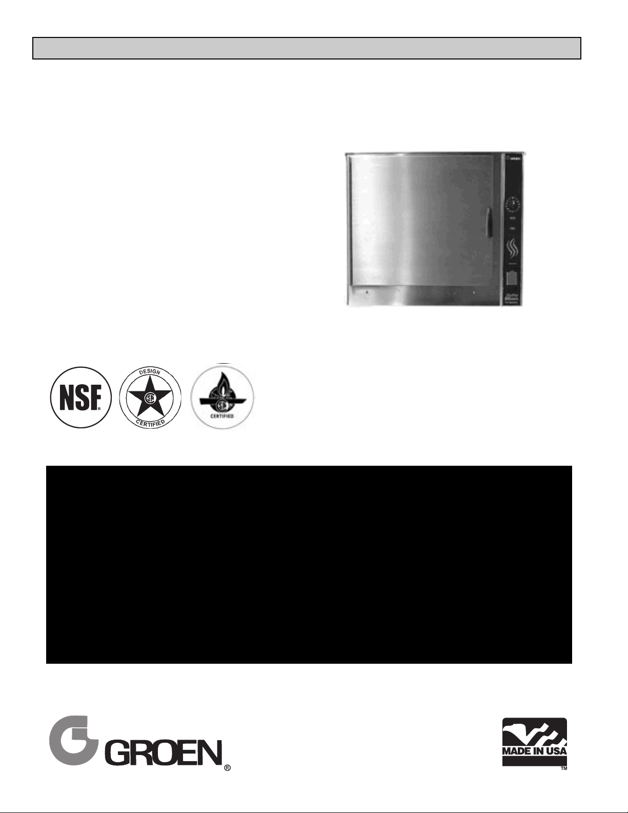
Model: HY-12GF, HY-24GF
HyCapacity HyPerSteam™
Atmospheric Convection
Steamer
Self-Contained
Gas Heated
® ®
THIS MANUAL MUST BE RETAINED FOR FUTURE REFERENCE. READ, UNDERSTAND
AND FOLLOW THE INSTRUCTIONS AND WARNINGS CONTAINED IN THIS MANUAL.
FOR YOUR SAFETY
DO NOT STORE OR USE GASOLINE OR OTHER FLAMMABLE VAPORS AND LIQUIDS IN
THE VICINITY OF THIS OR ANY OTHER APPLIANCE.
POST IN A PROMINENT LOCATION
INSTRUCTIONS TO BE FOLLOWED IN THE EVENT USER SMELLS GAS. THIS
INFORMATION SHALL BE OBTAINED BY CONSULTING YOUR LOCAL GAS SUPPLIER. AS
A MINIMUM, TURN OFF THE GAS AND CALL YOUR GAS COMPANY AND YOUR
AUTHORIZED SERVICE AGENT. EVACUATE ALL PERSONNEL FROM THE AREA.
WARNING: IMPROPER INSTALLATION, ADJUSTMENT, ALTERATION, SERVICE OR
MAINTENANCE CAN CAUSE PROPERTY DAMAGE, INJURY OR DEATH. READ THE
INSTALLATION, OPERATING AND MAINTENANCE INSTRUCTIONS THOROUGHLY BEFORE
INSTALLING OR SERVICING THIS EQUIPMENT.
Page 2

OM-HY-12G/24G
OM-HY-12G/24G
IMPORTANT — READ FIRST — IMPORTANT
WARNING: THE UNIT MUST BE INSTALLED BY PERSONNEL QUALIFIED TO WORK WITH
ELECTRICITY AND PLUMBING. IMPROPER INSTALLATION CAN CAUSE INJURY TO
PERSONNEL AND/OR DAMAGE TO THE EQUIPMENT. THE UNIT MUST BE INSTALLED IN
ACCORDANCE WITH APPLICABLE CODES.
CAUTION: DO NOT INSTALL THE UNIT IN ANY WAY WHICH WILL BLOCK THE RIGHT SIDE VENTS, OR
WITHIN 12 INCHES OF A HEAT SOURCE SUCH AS A BRAISING PAN, DEEP FRYER, CHAR
BROILER OR KETTLE.
NOTICE: Level the unit front to back, or pitch it slightly to the rear, to avoid drainage problems.
CAUTION: DO NOT LOCATE THE CABINET DIRECTLY OVER A FLOOR DRAIN OR FLOOR SINK.
HUMIDITY OR WATER FROM A DRAIN WILL DAMAGE ELECTRICAL PARTS OF A UNIT.
WARNING: TO AVOID DAMAGE OR INJURY, FOLLOW THE WIRING DIAGRAM EXACTLY WHEN
CONNECTING A UNIT.
WARNING: DO NOT CONNECT THE DRAIN DIRECTLY TO A BUILDING DRAIN.
CAUTION: DO NOT USE PLASTIC PIPE. DRAIN MUST BE RATED FOR BOILING WATER.
WARNING: BLOCKING THE STEAM GENERATOR OR CAVITY DRAIN SCREEN MAY BE HAZARDOUS.
IMPORTANT: Improper drain connection will void warranty.
WARNING: WHEN YOU OPEN THE DOOR, STAY AWAY FROM STEAM COMING OUT OF THE UNIT.
STEAM CAN CAUSE BURNS.
WARNING: BEFORE CLEANING THE OUTSIDE OF THE STEAMER, DISCONNECT THE ELECTRIC
POWER SUPPLY. KEEP WATER AND CLEANING SOLUTIONS OUT OF CONTROLS AND
ELECTRICAL COMPONENTS. NEVER HOSE OR STEAM CLEAN ANY PART OF THE UNIT.
WARNING: ALLOW COOKING CHAMBERS TO COOL BEFORE CLEANING.
WARNING: CAREFULLY READ THE WARNINGS AND FOLLOW THE DIRECTIONS ON THE LABEL OF
EACH CLEANING AGENT.
USE SAFETY GLASSES AND RUBBER GLOVES AS
RECOMMENDED BY DELIMING AGENT MANUFACTURER.
WARNING: DO NOT MIX DE-LIMING AGENTS (ACID) AND DE-GREASERS (ALKALI) IN THE STEAM
GENERATOR OR ON THE COOKING CHAMBER WALLS.
WARNING: DO NOT PUT HANDS OR TOOLS INTO THE COOKING CHAMBER UNTIL THE FAN HAS
STOPPED TURNING.
WARNING: DO NOT OPERATE THE UNIT UNLESS THE REMOVABLE RIGHT SIDE PANELS HAVE BEEN
RETURNED TO THEIR PROPER LOCATIONS.
NOTICE: Do not use a cleaning or de-liming agent that contains any sulfamic acid or any chloride,
including hydrochloric acid. If the chloride content of any product is unclear, consult the
manufacturer.
WARNING: USE OF ANY REPLACEMENT PARTS OTHER THAN THOSE SUPPLIED BY GROEN OR
THEIR AUTHORIZED DISTRIBUTOR VOIDS ALL WARRANTIES AND CAN CAUSE BODILY
INJURY TO THE OPERATOR AND DAMAGE THE EQUIPMENT. SERVICE PERFORMED BY
OTHER THAN FACTORY-AUTHORIZED PERSONNEL WILL VOID ALL WARRANTIES.
WARNING: HIGH VOLTAGE EXISTS INSIDE CONTROL COMPARTMENTS. DISCONNECT FROM
BRANCH BEFORE SERVICING. FAILURE TO DO SO CAN RESULT IN SERIOUS INJURY OR
DEATH.
2
Page 3

OM-HY-12G/24G
OM-HY-12G/24G
Table of Contents
IMPORTANT OPERATOR SAFETY WARNINGS . . . . . . . . . . . . . . . . . . . . . . . . . . . . . . . . . . 2
REFERENCES . . . . . . . . . . . . . . . . . . . . . . . . . . . . . . . . . . . . . . . . . . . . . . . . . . . . . . . . . . . . . 3
EQUIPMENT DESCRIPTION . . . . . . . . . . . . . . . . . . . . . . . . . . . . . . . . . . . . . . . . . . . . . . . . . . 4
WATER CONDITIONING . . . . . . . . . . . . . . . . . . . . . . . . . . . . . . . . . . . . . . . . . . . . . . . . . . . . . 4
INSTALLATION AND START-UP INSTRUCTIONS . . . . . . . . . . . . . . . . . . . . . . . . . . . . . . . . . 6
OPERATING INSTRUCTIONS . . . . . . . . . . . . . . . . . . . . . . . . . . . . . . . . . . . . . . . . . . . . . . . . 10
CLEANING . . . . . . . . . . . . . . . . . . . . . . . . . . . . . . . . . . . . . . . . . . . . . . . . . . . . . . . . . . . . . . . 13
MAINTENANCE . . . . . . . . . . . . . . . . . . . . . . . . . . . . . . . . . . . . . . . . . . . . . . . . . . . . . . . . . . 14
TROUBLESHOOTING . . . . . . . . . . . . . . . . . . . . . . . . . . . . . . . . . . . . . . . . . . . . . . . . . . . . . . 15
PARTS LIST . . . . . . . . . . . . . . . . . . . . . . . . . . . . . . . . . . . . . . . . . . . . . . . . . . . . . . . . . . . . . . 16
SCHEMATICS . . . . . . . . . . . . . . . . . . . . . . . . . . . . . . . . . . . . . . . . . . . . . . . . . . . . . . . . . . . . 18
SERVICE LOG . . . . . . . . . . . . . . . . . . . . . . . . . . . . . . . . . . . . . . . . . . . . . . . . . . . . . . . . . . . . 19
WARRANTY . . . . . . . . . . . . . . . . . . . . . . . . . . . . . . . . . . . . . . . . . . . . . . . . . . . . . . . . . . . . . . 20
References
AMERICAN NATIONAL STANDARDS INSTITUTE
1403 Broadway
New York, New York 10018
Z21.30 Installation of Gas Appliances &
Piping
Z223.1 1984 National Fuel Gas Code
NATIONAL FIRE PROTECTION ASSOCIATION
60 Battery March Park
Quincy, Massachusetts 02269
NFPA/54 Installation of Gas Appliances & Piping
NFPA/70 The National Electric Code
AMERICAN GAS ASSOCIATION LABORATORIES
8501 East Pleasant Valley Road
Cleveland, Ohio 44131
NATIONAL SANITATION FOUNDATION
3475 Plymouth Road
Ann Arbor, Michigan 48106
ZEP MANUFACTURING
1390 Lunt Avenue
Elk Grove Village, Illinois 60007
NSF INTERNATIONAL
789 N. Dixboro Rd.
P.O. Box 130140
Ann Arbor, Michigan 48113-0140
3
Page 4
OM-HY-12G/24G
OM-HY-12G/24G
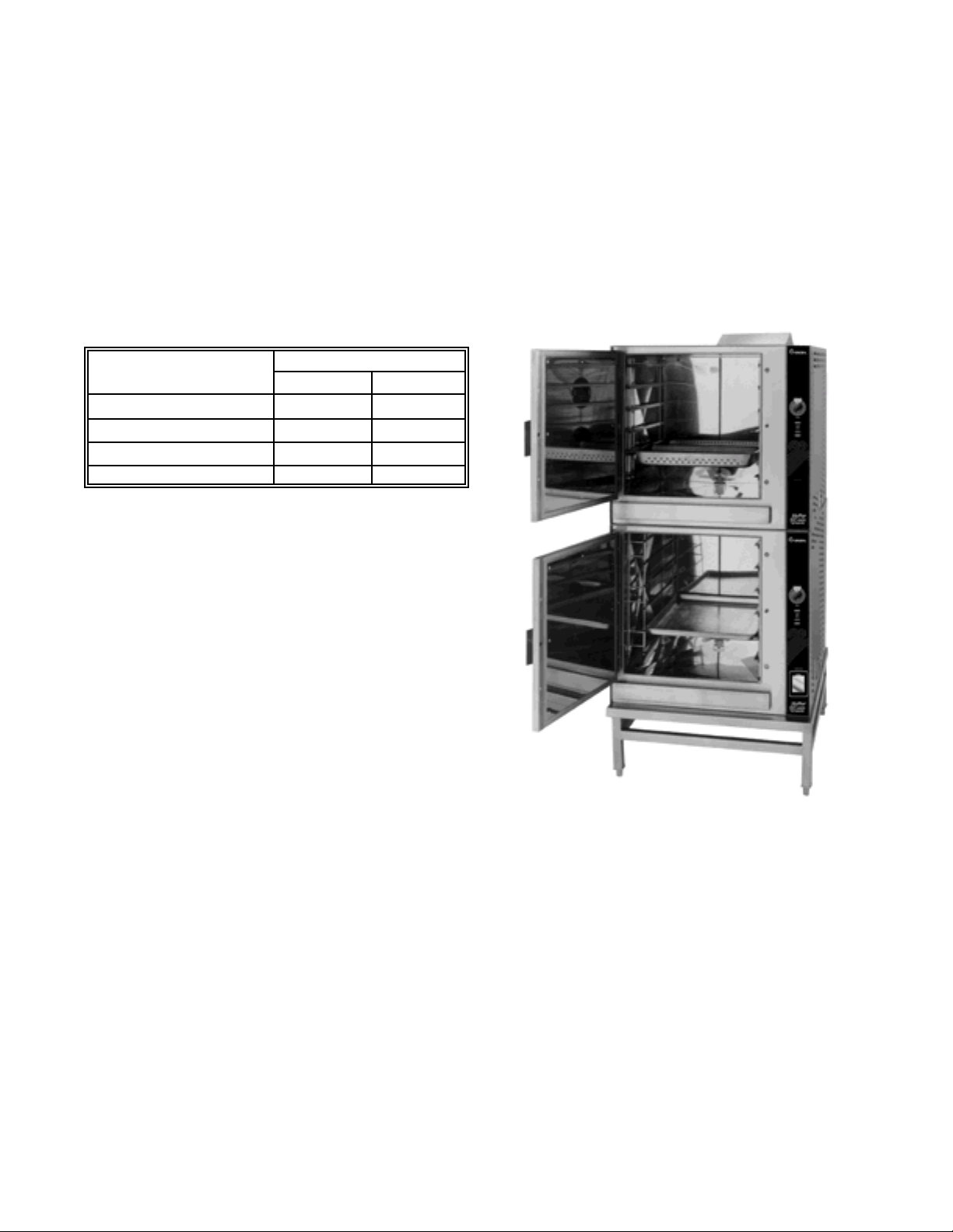
HY-24GF - New Model
Equipment Description
Your Groen HY-12GF HyCapacity HyPerSteam is
designed to give years of service. It consists of a
stainless steel cavity (cooking chamber) which is served
by an electrically-heated atmospheric steam generator.
The HY-24GF has two cavities and two generators.
Two powerful blowers circulate the steam in each cavity
to increase heating efficiency.
A dual position pan rack on the left side of the cavity
can be quickly changed to allow for the use of either 12"
x 20" steamer pans, or 18" x 26" bake pans. The
following table lists pan capacities:
Pan Size/Type
Number of Pans
HY-12GF HY-24GF
12 x 20 x 2½” (steamer) 12 24
12 x 20 x 4" (steamer) 8 16
13 x 18" (half-size bake) 24 48
18 x 26" (bake) 12 24
A stainless steel cabinet encases the cavity, steam
generator and a control compartment which houses
electrical components. Access to the control
compartment is gained by removing the right side
louvered panel. Door hinges are reversible so that the
door may be opened to the left or right. Operating
controls are on the front panel.
Newer model HY-12GF and HY-24GF steamers
(manufactured since November 1999) are equipped
with fully electronic controls and a button-activated preprogrammed CLEAN cycle.
These units are readily identified by their unique
control panels. Touch pad controls, and the distinctive
symbol for steam is integrated into the panel design.
The new models also have fewer panel louvers on the
right side and rear.
The drain system for each cavity includes a spray
condenser, which helps keep steam from coming out
of the unit drain or entering the building drain.
Water Conditioning
It is essential to supply the steam generator with
water that will not form scale. Although the steam
generators are engineered to minimize scale, the
hardness of your water and number of hours the
equipment operates influence scale build-up.
In some areas of the country, water is low enough in
minerals to avoid scale formation. But most water
supplies are full of minerals which form scale. It is
this scale which could lead to an early component
failure. Your water utility or treatment specialists can
test and tell you about the minerals in your water.
Water to the steam generator should have between
10 and 30 parts per million (ppm) total dissolved
solids (TDS) and should have a pH (acidity rating) of
7.0 or higher.
4
Page 5
OM-HY-12G/24G
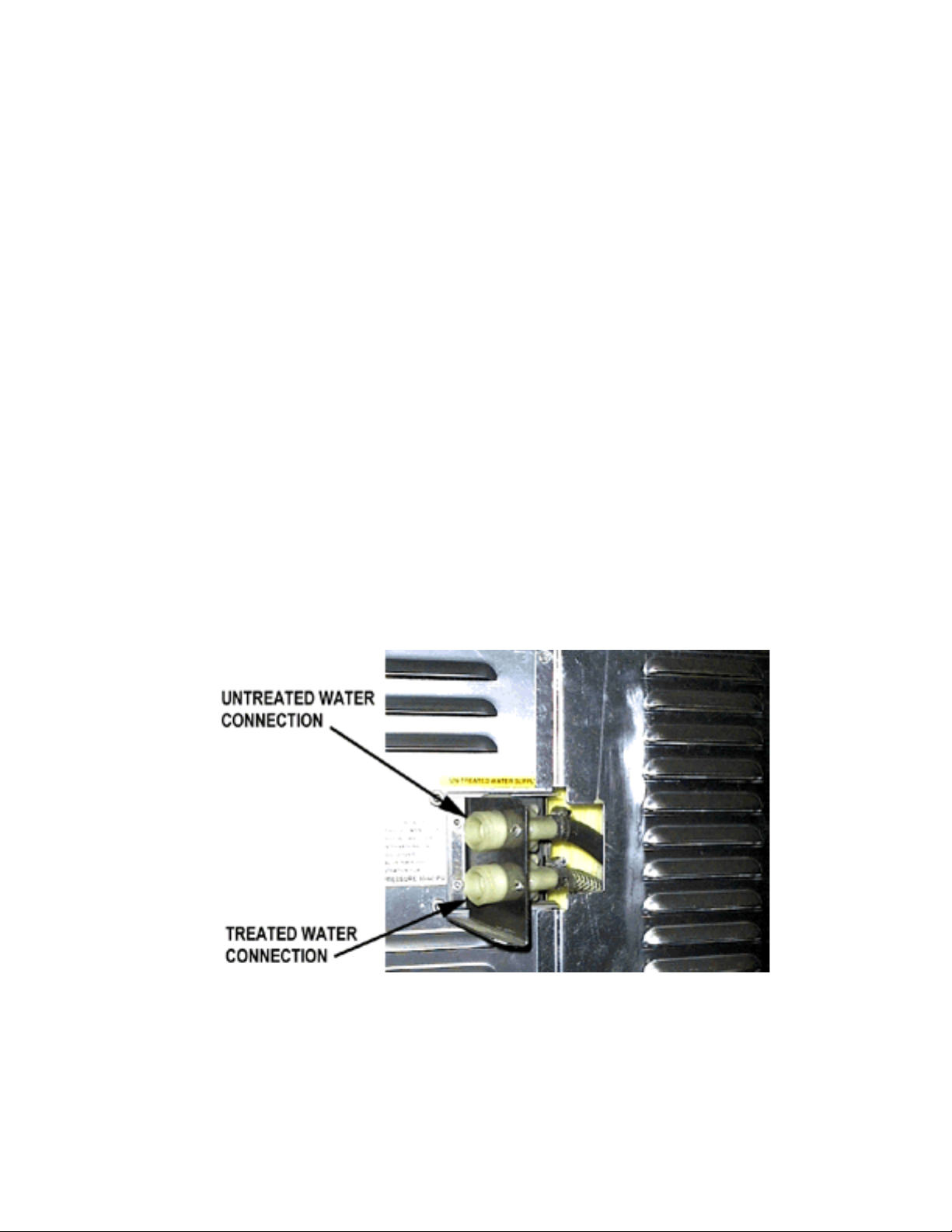
The optional separate water intake could significantly reduce treated water
requirements.
Please follow these simple precautions:
1. The best way to prevent scale is to use a
Groen PureSteem™ Water Treatment
System which has been specifically
designed for Groen steamers and
combination ovens. Do not rely on
unproven water treatment systems sold
for scale prevention and removal. They are
not specifically designed to work with
Groen steamers and combination ovens.
2. A well-maintained water treatment system
and a regular cartridge replacement
schedule is essential.
3. Using a Groen PureSteem™ Water
Treatment System will provide longer steam
generator/boiler life, higher steam capacity,
and reduce maintenance requirements.
4. If you notice a slowdown in steam production
or an increase in deliming, have the steamer
checked for scale build-up. This could be an
indication that the water treatment cartridges
need replacing. Heavy scale reduces the
unit’s ability to boil water, and can even
cause component failure.
OM-HY-12G/24G
5
Page 6
OM-HY-12G/24G
OM-HY-12G/24G
Installation and Start-Up
WARNING
THE UNIT MUST BE INSTALLED BY PERSONNEL WHO ARE QUALIFIED TO WORK WITH ELECTRICITY
AND PLUMBING. IMPROPER INSTALLATION CAN CAUSE INJURY TO PERSONNEL AND/OR DAMAGE TO
THE EQUIPMENT. THE UNIT MUST BE INSTALLED IN ACCORDANCE WITH APPLICABLE CODES.
CAUTION
DO NOT INSTALL WITH THE RIGHT SIDE VENTS BLOCKED OR WITHIN 12 INCHES OF A HEAT SOURCE
(BRAISING PAN, DEEP FRYER, CHAR BROILER, OR KETTLE).
TO AVOID DRAINAGE PROBLEMS, LEVEL THE UNIT FRONT TO BACK.
HY-12GF
UTILITY CONNECTIONS:
1. Electrical connection ½” (13 mm) conduit fitting.
2. Cold water supply connection ¾” (19 mm) hose
3. Drain connection 2½” (64 mm) hose connection
4. Gas connection ¾” (19 mm) NPT
HY-24GF
UTILITY CONNECTIONS:
1. Electrical connections (each cavity) ½” (13 mm)
conduit fitting.
2. Cold water supply connection (each cavity) ¾” (19
mm) hose
3. Drain connection 2½” (64 mm) hose connection
4. Gas connection (each cavity) ¾” (19 mm) NPT
BURNER FIRING RATES PER CAVITY ELECTRICAL SPECIFICATIONS
Natural Gas @ 3.1" WC L.P. Gas at 10" WC Voltage: 108-126V 1 Phase 50/60 Hz
BTU/hr HY-12G 160,000 150,000 Current per cavity 2.5 AMPS ± 10%
6
Page 7
OM-HY-12G/24G
A. Installation
When the steamer is received, immediately inspect
the unit thoroughly for external and internal damage.
Report any damage to the carrier.
After the inspection, keep the unit in its shipping
container until it is installed.
The HY-12GF steamer is suitable for installation in
combustible and noncombustible locations. The
flooring in all installations must be noncombustible
material. Minimum installation clearances are:
Right Side Two inches (50 mm)
Left Side Zero inches
Rear of flue Six inches (300 mm)
CAUTION
THE HY-12G STEAMER REQUIRES 24 INCHES
(610 MM) CLEARANCE ON THE RIGHT SIDE
FOR PROPER SERVICE.
The unit must be installed in an adequately ventilated
room with provision for adequate air supply. It must
be installed under a ventilation hood, since flue
products exit the appliance. Items which might
obstruct or restrict air flow for combustion and
ventilation must be removed. Do not obstruct the flue
cover or any vents after installation. Areas around
the unit must be cleared of combustible material.
The installation must conform with local codes or, in
the absence of local codes, with the National Fuel
Gas Code, ANSI Z223.1-latest edition, including:
“The appliance and its individual shutoff valve
must be disconnected from the gas supply
piping system during any pressure testing of that
system at pressures in excess of ½ PSI (3.45
kPa). The appliance must be isolated from the
gas supply piping system by closing its individual
manual shutoff valve during any pressure testing
of the gas supply piping system at pressures
equal to or less than ½ PSI (3.45 kPa).
CAUTION
MAKING ANY ELECTRICAL OR MECHANICAL
CHANGE IN THE UNIT WITHOUT PRIOR
APPROVAL FROM THE GROEN FOOD SERVICE
ENGINEERING DEPARTMENT MAY VOID ALL
WARRANTIES.
1. Electrical Supply Connection
Provide 115 VAC, 60 HZ, 1 PH, 15 AMP service.
Bring conduit in through open frame on under
side of cabinet. Local codes and/or the National
Electrical Code should be observed in
accordance with ANSI/NFPA 70-1987 (or latest
edition). AN ELECTRICAL GROUND IS
REQUIRED. The electrical schematic is located
in the service compartment and in this manual.
Maximum load is 2 1/2 amps. In Canada
,
provide electrical service in accordance with the
Canadian Electrical Code, CSA C22.1 Part 1
and/or local codes.
WARNING
TO AVOID DAMAGE OR INJURY, FOLLOW THE
ELECTRICAL SCHEMATIC EXACTLY WHEN
CONNECTING THE UNIT.
2. Gas Supply Connection
Connection to the gas supply can be completed
with ¾” NPT pipe or approved equivalent.
Although the immediate connection to the
appliance is ¾” NPT, gas supply piping must be
large enough to provide 160,000 BTU/hr. Supply
pressure must be at least 5” W.C. (maximum
14” W.C.) for natural gas or 11” W.C. (maximum
14” W.C.) for LP gas. In Canada, the installation
must conform to the Canadian Gas Code, CAN
1-B149, Installation Codes for Gas Burning
Appliances and Equipment and/or local codes.
After the unit has been connected to the gas
supply, all gas joints must be checked for leaks
.
No flame should be used when checking for
leaks. A thick soap solution or other suitable leak
detector should be used. The unit must have a
separate ground wire for safe operation. This
wire must be at least 8 AWG for 208/240V, or 10
AWG for 480V.
3. Water Connection(s)
Install a check valve to prevent back flow in the
incoming cold water line, as required by local
plumbing codes. Water pressure in the line
should be between 30 and 60 PSI (210 and 420
kPa). If pressure is above 60 PSI, a pressure
OM-HY-12G/24G
7
Page 8
OM-HY-12G/24G
OM-HY-12G/24G
Installation of drain line without drain box .
regulator will be needed. A ¾ inch R connector
(garden hose type) is used to attach the water
supply to the water inlet valve. The minimum
water feed line diameter is ½ inch (13mm). Use
a washer in the hose connection. Do not allow
the connection to leak, no matter how slowly.
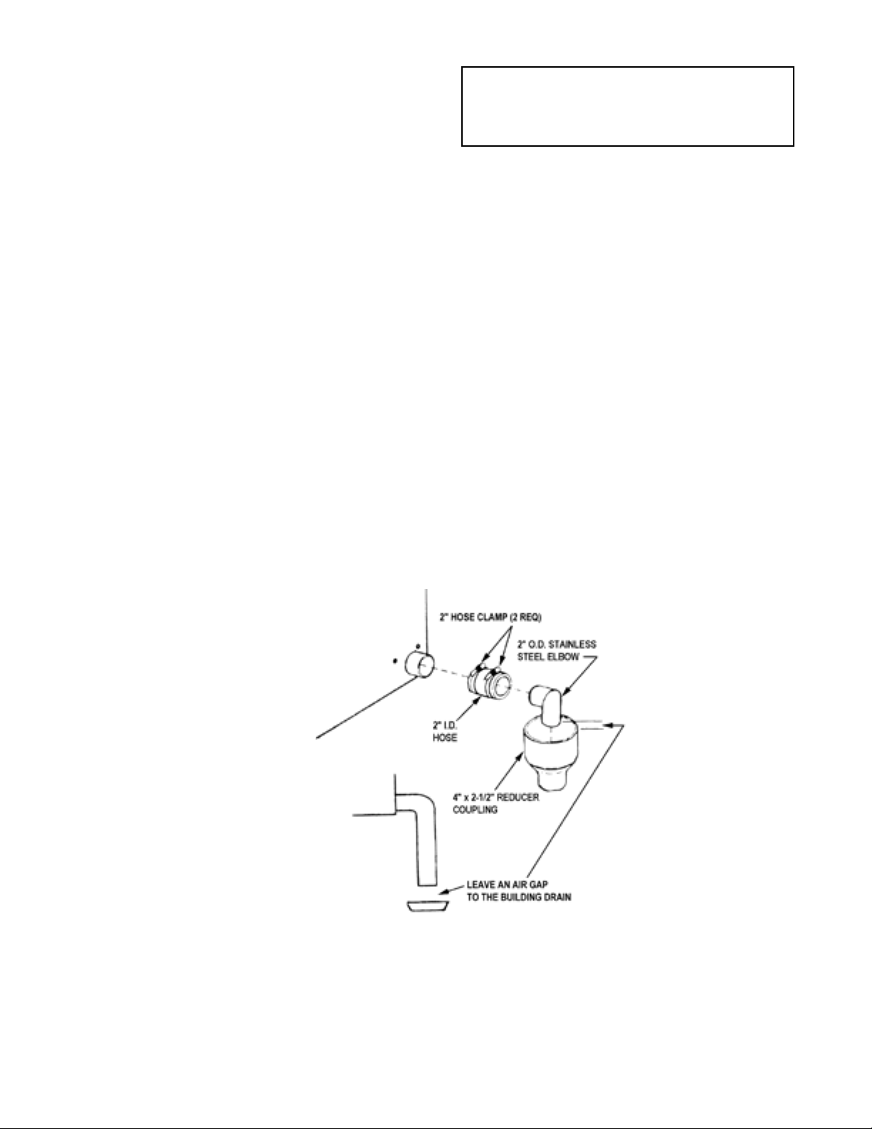
3. Drain Connection
Your HY-12GF/24GF Steamer must be leveled
front to back or pitched slightly to the rear by
adjustment of the bullet feet on the cabinet base.
All units are shipped from the factory with a drain
box and vent pipe. The drain box and vent pipe
provide the necessary air gap when properly
installed. The illustrations below show proper
installation of drain lines from the drain box, and
for tabletop installation, without a drain box.
CAUTION
DO NOT CONNECT THE HOSE DIRECTLY TO
A BUILDING DRAIN. BLOCKING THE DRAIN
COULD BE DANGEROUS.
Do not create any water traps in the drain line. A
trap would cause pressure to build up inside the
cavity during steaming and make the door gasket
leak.
NOTE: Improper drain connection will void the
warranty.
INSTALLATION OPTION ONE: From stainless
steel elbow (P/N 092273) to nearby floor drain, use
Radiator Hose (rated for at least 212ºF) and one
additional hose clamp (P/N 013616).
INSTALLATION OPTION TWO: Using the hose
(P/N 080688) and two hose clamps (P/N 013616),
connect two inch copper tube to floor drain. NOTE:
Drain lines must be pitched downward at
approximately ½ inch per foot. No water traps
should be allowed in the drain line.
IMPORTANT: Leave two inches free air gap to
building drain.
8
Page 9

OM-HY-12G/24G
B. Initial Start-Up
After the Steamer has been installed, test it to
ensure that the unit is operating correctly.
1. Remove all literature and packing materials
from the interior and exterior of the unit.
2. Make sure the water supply line is open.
3. Make sure that the gas supply line is open
and that the manual knob on the main gas
valve is turned to the “on” position. This
valve is located behind the access panel on
the right side of the unit.
4. Turn on electrical service to the unit. The
unit will not operate without electrical power.
Do not operate during a power failure.
5. The steamer will not operate until the pilot
burner has been ignited. To light the pilot
burner, activate the pilot switch located next
to the main gas valve. When the pilot
ignition sequence has been successfully
completed, a green light - on the pilot switch
- and on the electrical panel (new models)
will glow.
6. The “trial for ignition” period is roughly 90
seconds. If the pilot burner does not light
within about 90 seconds after the switch is
activated, the ignition system automatically
stops gas flow to the pilot burner and stops
the ignition trial. If this happens, turn off the
pilot switch and repeat the trial for ignition.
During the initial start-up, the pilot may
require several trials for ignition until all the
air is bled from the gas piping. Subsequent
start-ups should require only about 5
seconds to achieve pilot ignition.
NOTE: See Automatic Operation of Pilot at
the end of this section.
7. Once the pilot burner flame has been
established (the green light on the pilot
switch or electrical panel (new models) is
on), press the “ON” switch for the desired
steamer cavity. The steam generator will fill
with water.
NOTE: The door MUST be closed for the
main burner to work.
8. When the steam generator has filled with
water, the main burner will ignite
automatically. Within 6-8 minutes the
READY light will come on, indicating that the
water has reached its standby temperature.
When the READY light is displayed, you may
take any one of the following steps:
a. Set the timer to the desired time for
timed steaming.
b. Turn the timer knob to the manual ON
position for continuous steam.
c. Let the unit stay at standby temperature.
WARNING
WHEN YOU OPEN THE DOOR, STAY AWAY
FROM STEAM COMING OUT OF THE UNIT. THE
STEAM CAN CAUSE BURNS.
9. To shut down the unit, press the ON switch
into the off position. The steam generator
will then drain. You may also switch off the
pilot switch to conserve energy.
10. If the HY-12/24G Steamer behaves as
described, the unit is functioning correctly
and ready for use.
Automatic Operation of Pilot
Once the pilot burner is lit, it essentially functions as
a standing pilot. In this state, if the pilot is
accidentally extinguished (by a very strong gust of
wind for example), it will re-ignite automatically. The
unit will completely shut down for a few seconds
while the pilot is re-ignited. Then the unit will come
back on and resume operation in the mode and with
the (running) timer value existing just prior to
shutdown. The pilot switch may be turned off during
“off hours” to conserve energy.
After the unit has been running, if the pilot burner
ever fails to re-ignite automatically within 90
OM-HY-12G/24G
9
Page 10

OM-HY-12G/24G
OM-HY-12G/24G
seconds, wait 5 minutes before you attempt to
reactivate it. In the unlikely event that ignition
problems persist, contact your authorized Groen
Service Agency.
NOTE: For operation at high altitudes (2000 feet and
above) please consult the Groen Food Service
Engineering Department.
Operation
WARNING
ALL POTENTIAL USERS OF THE EQUIPMENT SHOULD BE TRAINED IN SAFE AND CORRECT OPERATING
PROCEDURES.
NO ATTEMPT SHOULD BE MADE TO OPERATE THIS EQUIPMENT DURING A POWER FAILURE.
NOTE: Before the steamer can be operated as described in this section, the pilot burner flame must be
established. For details see the Initial Start-Up section and the Automatic Operation of Pilot, above.
A. Controls (See Illustration)
Operator controls are on the front right of the unit.
The control panel on new models has the following
touch pads and indicator lights:
! The ON/OFF touch pad gets the
HyPerSteam ready for use, or shuts it off.
! The READY indicator light shows that the
steam generator is at standby temperature
and the cavity is hot enough to begin
steaming.
! The DELIME indicator light is lit when the
unit is operating in the cleaning mode.
! The SERVICE indicator light shows when
the water level probes have stopped
working, and need to be cleaned (normally
an indication of lime deposits).
When one probe is not working, the
SERVICE light flashes briefly every few
seconds. If both probes fail, the light
flashes continuously and the beeper will
sound.
! The HI TEMP indicator light comes on when
the steam generator is too hot.
The unit will automatically shut off, and
cannot be turned on again until the steam
generator cools and the HI TEMP indicator
light goes out.
! The TIMING indicator light stays on when
the timer is running.
! The CLEAN touch pad is used to start the
automatic 30 minute cleaning cycle.
The timer is used in three ways:
1 In the OFF position the steam generator
stays at a “holding” temperature.
2 When a cook time is set, the unit steams
until the timer runs down to OFF. Steaming
stops, the DONE light comes on and a
beeper sounds.
10
Page 11

OM-HY-12G/24G
60 Minute Timer
Manual “ON Position
Power ON/OFF Button
Power Indicator Light
Ready Indicator Light
Service Indicator Light
Clean Cycle Button
High Temp
Indicator Light
Deliming Port
Delime [In progress]
Indicator Light
Manual “ON PositionManual “ON Position
HY-12G Control Panel
OM-HY-12G/24G
11
Page 12

OM-HY-12G/24G
OM-HY-12G/24G
3 With the timer turned to the ON position, the
unit steams continuously. The green light
stays lit. The steamer will not time down.
B. Operating Procedure
1. Press the ON switch/pad for the steamer. The
steam generator will fill, and heat until the
READY light comes on. (About 10 minutes.)
2. Load food into pans in uniform layers. Pans
should be filled to about the same levels, and
should be even on top.
3. Open the door and slide the pans onto the
supports. If you will only be steaming one pan,
put it in the middle position.
4. Close the door. With the READY indicator lit,
take one of the following steps:
! If you want to steam the food for a certain
length of time, set the timer for that period.
The timer will automatically run the steamer
for the set time and then turn it off.
A red light will come on and a beeper will
sound. Steam production stops.
! If you want to steam continuously, turn the
timer to the manual ON position. A green
light will come on. The unit will continue
steaming until you stop it by turning the
timer to OFF. When steaming continuously
YOU MUST CONTROL STEAMING TIME.
WARNING
WHEN YOU OPEN THE DOOR, STAY AWAY
FROM THE STEAM COMING OUT OF THE UNIT.
THE STEAM CAN CAUSE BURNS.
5. Open the door. Remove the pans from the
steamer, using hot pads or oven mitts to protect
your hands from the hot pans.
6. To shut down the unit, press the ON switch/pad
to OFF. The steam generator will automatically
drain.
12
Page 13

OM-HY-12G/24G
Cleaning
To keep your steamer in proper working condition,
clean it periodically by the following procedure.
Regularly scheduled cleaning will reduce the effort
required in cleaning the steam generators and
cavities.
A. Suggested Supplies
1. Mild detergent
2. Stainless steel exterior cleaner, like Zepper
from Zep Manufacturing Company.
3. Groen Delimer p/n114800, Lime-A-Way (from
Ecolab) or equivalent de-liming agent. De-liming
agent should contain phosphoric acid, not to
exceed 30% total volume. See warning about
chlorides and sulfamic acid below.
4. Groen Spray Degreaser p/n140830.
5. Cloth or sponge
6. Plastic wool or a brush with soft bristles
7. Spray bottle
8. Measuring cup
9. Nylon pad
10. Towels
11. Plastic disposable gloves
12. Funnel
B. Procedure
1. Unit Exterior
a. Prepare a warm solution of mild detergent as
instructed by the supplier. Wet a cloth with this
solution and wring it out. Use the moist cloth to
clean the outside of the unit. Do not allow
freely running liquid to touch the flue, exhaust
outlet, controls, control panel, any electrical
part, or any open louver.
b. To remove materials stuck to the unit, use
plastic wool, a fiber brush, or a plastic or rubber
scraper with detergent solution. Do not use any
metal material (such as metal sponges) or metal
implements (such as a spoon, scraper, or wire
brush) that might scratch the surface. Scratches
make the surface hard to clean and provide
places for bacteria to grow. Do not use steel
wool, which may leave particles imbedded in the
surface and cause corrosion and pitting.
WARNING
BEFORE CLEANING THE OUTSIDE OF THE
STEAMER, DISCONNECT THE ELECTRIC
POWER SUPPLY.
KEEP WATER AND CLEANING SOLUTIONS
OUT OF CONTROLS AND ELECTRICAL
COMPONENTS. NEVER HOSE OR STEAM
CLEAN ANY PART OF THE UNIT.
DO NOT MIX DE-LIMING AGENTS (ACID) AND
DE-GREASERS (ALKALI) ANYWHERE IN THE
UNIT.
TAKE PRECAUTIONS TO AVOID CONTACT
WITH ANY CLEANERS, DE-LIMING AGENT,
OR DE-GREASER, AS RECOMMENDED BY
THE SUPPLIER. MANY CLEANERS ARE
HARMFUL TO THE SKIN, EYES, MUCOUS
MEMBRANES, AND CLOTHING. CAREFULLY
READ THE WARNINGS AND FOLLOW THE
DIRECTIONS ON THE LABEL OF EACH
CLEANING AGENT.
EVEN WHEN THE UNIT HAS BEEN SHUT OFF,
DO NOT PUT HANDS OR TOOLS INTO THE
COOKING CHAMBER UNTIL THE FAN HAS
STOPPED TURNING.
DO NOT OPERATE THE UNIT UNLESS THE
TWO REMOVABLE INTERIOR PARTITIONS
HAVE BEEN RETURNED TO THEIR PROPER
LOCATIONS.
DO NOT USE A CLEANING OR DE-LIMING
AGENT THAT CONTAINS ANY SULFAMIC
ACID OR ANY CHLORIDE, INCLUDING
HYDROCHLORIC ACID (HCI). TO CHECK FOR
CONTENT OF THESE SUBSTANCES, REFER
TO THE "MATERIAL SAFETY DATA" SHEET
PROVIDED BY THE CLEANING AGENT
MANUFACTURER.
IMPORTANT
DO NOT USE ANY METAL MATERIAL (SUCH AS METAL SPONGES) OR METAL IMPLEMENTS (SUCH AS
A SPOON, SCRAPER OR WIRE BRUSH) WHICH MIGHT SCRATCH THE SURFACE. SCRATCHES MAKE THE
SURFACE HARD TO CLEAN AND PROVIDE PLACES FOR BACTERIA TO GROW. DO NOT USE STEEL
WOOL, WHICH MAY LEAVE PARTICLES IMBEDDED IN THE SURFACE, WHICH COULD EVENTUALLY
CAUSE CORROSION AND PITTING.
c. Stainless steel surfaces on the outside of the unit may be polished with a recognized
OM-HY-12G/24G
13
Page 14

OM-HY-12G/24G
OM-HY-12G/24G
stainless steel cleaner (Zepper, etc.).
2. Steam Generator and Cooking Chamber:
Regular deliming, depending on your steamer
usage and local water quality, must be done to
enhance performance and prolong the life of your
HyPerSteam™ convection steamer. Steamer
must be turned off after every use to prevent lime
scale buildup - do not run steamer continuously.
ALWAYS USE HOT PADS OR MITTS WHEN
HANDLING HOT STEAMER PANELS OR
RACKS.
RECOMMENDED TOOLS & CLEANERS:
- Groen Delimer/Descaler (Part Number
114800). Do NOT use any product
containing chlorides or sulfamic acid,
including hydrochloric acid .
- Nylon scrub pad, cloth and/or sponge
DELIMING STEPS (Use Touch Pad):
STEP 1 Press ON/OFF to turn steamer off.
Open door
STEP 2 Let cavity cool for 5 minutes or
longer. While cool, wipe out cavity.
STEP 3 Pour 2 pints (4 cups) of delimer into
deliming port before delime cycle is
started and then close port. Doublestacked unit cavities must be delimed
separately. Select which cavity to
delime first.
STEP 4 Press and hold CLEAN while also
turning steamer on by pressing ON/OFF,
until only DELIME and POWER lights
remain on (all lights will turn on, then off,
except DELIME and POWER).
STEP 5 Delime cycle will start, taking about 30
minutes. When delime cycle is
complete, DELIME light will appear,
DONE light will flash and beeper will
beep.
STEP 6 Press ON/OFF to turn steamer off. Let
cavity cool for 5 minutes or longer.
Open door, wipe out inside of cavity and
wipe door gasket. Close door.
STEP 7 To use steamer, press ON/OFF. When
READY light appears, steamer is ready
To use.
STEP 8 HY12E/HY12G DOUBLE STACK
ONLY: Double-stacked unit cavities
must be delimed separtely. Repeat Step
1 through Step 8 to delime other
cavity.
NOTES:
- If DELIME light flashes rapidly (5 times per
second), press DELIME to restart delime cycle.
- If power outage occurs during deliming, delime
cycle must be restarted. Press DELIME.
- For best performance, do not interrupt delime
cycle. If delime cycle must be stopped, press
ON/OFF to turn on. Set timer for 5 minutes. After
beeper beeps, press ON/OFF to turn off. Let cavity
cool for 5 minutes or longer, carefully open door(s)
and wipe out cavity completely.
Maintenance
The HY-12G Steamer is designed for minimum
maintenance, and no user adjustments should be
necessary. Certain parts may need replacement
after prolonged use.
If there is a need for service, only Groen personnel
or authorized Groen representatives should perform
the work.
Always supply water with a low mineral content that
meets the standards outlined in the Water
Conditioning section of this manual.
If steam or condensate is seen leaking from around
the door, take the following steps:
1. Check the door gasket. Replace it if it is cracked
or split.
2. Inspect the cooking chamber drain to be sure it
is not blocked.
14
Page 15

OM-HY-12G/24G
Adjust the door latch pin to allow for changes
that might occur as the gasket ages
3. Adjust the door latch pin to allow for changes that
might occur as the gasket ages.
a. Loosen the lock nut at the base of the latch
pin, then turn the latch pin ¼ turn clockwise,
and tighten the lock nut.
b. After adjustment, run the unit to test for further
steam leakage.
c. If there is still leakage, repeat the adjustment.
d. Continue adjusting the pin clockwise until the
door fits tightly enough to prevent leakage.
NOTE: It is important that the flue outlet be checked
regularly. Debris covering the flue outlet can cause a
potentially hazardous condition. Remove any foreign
material before using this equipment.
Troubleshooting
The Groen Steamer is designed to operate smoothly and efficiently if properly maintained. However, the
following is a list of checks to make in the event of a problem. Wiring diagrams are furnished inside the service
panel and at the back of this manual. If an item on the check list is marked with (
�), it means that the work
should be done by a factory-authorized service representative.
SYMPTOM WHO
WHAT TO CHECK
����indicates items which must be performed by an authorized technician.
Pilot will not light User a. Are electrical connections made with a ground?
b. Is gas supply connection made?
c. Is pilot ignition switch activated?
d. Is gas valve turned on?
e. Are building fuses or circuit breakers all right?
f. Are there drafts which might blow out the pilot?
Auth Service Rep
Only
g. Is spark ignition cable connected to pilot module?
�
Steam generator does not fill with
water.
User a. Is the ON switch depressed?
b. Is electric supply connected?
c. Is the water supply connected?
d. Low water pressure (below 30 PSI or 210 kPa)?
e. Is the screen at the water connection clogged?
f. Has the steam generator been delimed?
Pilot will light, but main burners will
not light.
User a. Is “ON” swtich depressed?
b. Is water supply connected?
c. Are steamer doors open?
d. Is water screen or filter clogged?
Pilot will light, but no panel lamp
comes on
Call your authorized Groen Service Agency.
Service Light flashes. (New Models).
(See Cleaning Section)
User a. Is the water supply connected?
b. Is water supply hose kinked?
c. Is water screen or filter clogged?
d. Has the steam generator been delimed? (Refer to
Cleaning Section)
Excessive steam escaping from rear
of unit
User a. Is the water spray hose kinked or obstructed?
Auth Service Rep
Only
b. Is the water spray solenoid connected?
�
OM-HY-12G/24G
15
Page 16

OM-HY-12G/24G
16
Parts List
16
Page 17

OM-HY-12G/24G
17
Parts List
Key Description Part No. Key Description Part No. Key Description Part No.
1 Platform Assembly 141691 19 Screw, slotted, hex 8-32 x 1/4 074242 37 Tube, Manifold 1/2" O.D. 141707
2 Motor Assembly 146880 20 Nut, Rotary shaft seal 101145 38 Manifold Assembly 141708
3 Electronic Control Assembly 141699 21 Drip Shield, Motor 119844 39 Clamp, Double Wire 127662
4 Line Connection Assembly 119873 22 Harness, Ready/Door Switch 119878 40 Clamp, Hose 093482
5 Universal Thermostat 099947 23 Harness, Control Board Extension 141084 41 Reducer, Water Flow 106445
6 Plastisol Boot 101143 24 Switch, Rocker w/LED 119858 42 Boiler Assembly 141683
7 Valve, Water Inlet 2 way, triple 090827 25 Circuit Board Assembly 119875 43 Clamp, Constant Pressure 126011
8 Timer, Steamer, 60 Hz 096826 26
Capacitor, 7.5 µF
106271 44 Hose, Steam Inlet 1/2" dia 5-3/8 l. 106581
9 Knob, Timer 123100 27 Probe, Water (Short) 141285 45 Hose, Steam Inlet 1-1/2 I.D. x 13" 106578
10 Steamer Control PC Board Assy 141802 27 Probe, Water (Long) 141284 46 Hose, Steam Inlet 1-1/2 I.D. x 22" l. 106579
11 Light & Timer PC Board Assy 137233 28 Ignition Module 085153 47 Gas Valve, Natural Gas 098443
12 Standoff Hex, 6-32 x 3/4 119826 29 Transformer, 75 Amp, 24 VAC 106233 47 Gas Valve, Propane Gas 098444
13 Standoff Hex, 6-32 x 1-1/4 119827 30 Transformer, 20 VAC 119815 48 Valve, Gas, Manual 1/2" NPT 098458
14 Harness, Timer Motor 123120 31 Relay, 12 VDC Coil 119813 49 Not Shown
15 Jumper, Control Bd. To Display Bd. 123122 32 Relay, 24 VDC Coil 119814 50 Motor, Fan 096739
16 Cover, Control Panel 143255 33 Panel Overlay, Mylar 123131
17 Nut, Keps, 6-32 071289 34 Gas Valve Piping, Natural Gas 142380
18 Nut, lock, nylon insert 6-32 119855 34 Gas Valve Piping, Propane Gas 142381
17
Page 18

OM-HY-12G/24G
18
Schematic & Wiring Diagrams
18
Page 19

OM-HY-12G/24G
Service Log
Model No.
Serial No.
Date Purchased
Purchase Order No.
Purchased From
Location
Date Installed
For Service Call
Date Maintenance Performed Performed by
OM-HY-12G/24G
19
Page 20

OM-HY-12G/24G
OM-HY-12G/24G
LIMITED WARRANTY TO
COMMERCIAL PURCHASERS*
Continental U.S., Hawaii and Canadian Sales Only)
Groen Foodservice Equipment (“Groen Equipment”) has been skillfully manufactured, carefully inspected, and
packaged to meet rigid standards of excellence. Groen warrants its Equipment to be free from defects in material
and workmanship for (12) twelve months with the following conditions an subject to the following limitations.
I. This parts and labor warranty is limited to Groen Equipment sold to the original commercial
purchaser/users (but not original equipment manufacturers {O.E.M.}), at its original place of installation
in the continental United States, Hawaii and Canada.
II. Damage during shipment is to be reported to the carrier, is not covered under this warranty, and is the
sole responsibility of the purchaser/user.
III. Groen, or an authorized service representative, will repair or replace, at Groen’s sole election, any
Groen equipment, including but not limited to, drawoff valves, safety valves, gas and electric
components, found to be defective during the warranty period. As to warranty service in the territory
described above, Groen will absorb labor and portal to portal transportation costs (time and mileage) for
the first twelve (12) months from date of installation or fifteen (15) months from date of shipment from
Groen.
IV. This warranty does not cover boiler maintenance, calibration, periodic adjustments as specified in
operating instructions or manuals, and consumable parts such as scraper blades, gaskets, packing,
etc., or labor costs incurred for removal of adjacent equipment or objects to gain access to Groen
Equipment. This warranty does not cover defects caused by improper installation, abuse, careless
operation, or improper maintenance of equipment. This warranty does not cover damage caused by
poor water quality or improper boiler maintenance.
V. THIS WARRANTY IS EXCLUSIVE AND IS IN LIEU OF ALL OTHER WARRANTIES, EXPRESS OR
IMPLIED, INCLUDING ANY IMPLIED WARRANTY OF MERCHANTABILITY OR FITNESS FOR A
PARTICULAR PURPOSE, EACH OF WHICH IS HEREBY EXPRESSLY DISCLAIMED. THE
REMEDIES DESCRIBED ABOVE ARE EXCLUSIVE AND IN NO EVENT SHALL GROEN BE LIABLE
FOR SPECIAL, CONSEQUENTIAL OR INCIDENTAL DAMAGES FOR THE BREACH OR DELAY IN
PERFORMANCE OF THIS WARRANTY.
VI. Groen Equipment is for commercial use only. If sold as a component of another (O.E.M.)
Manufacturer’s equipment, or if used as a consumer product, such Equipment is sold AS IS and without
any warranty.
*(Covers all Foodservice Equipment Ordered after October 1, 1995)
20
Page 21

NOTES
Page 22

NOTES
Page 23

Page 24

1055 Mendell Davis Drive
Jackson, MS 39272
Telephone 601 372-3903
Fax 601 373-9587
www.groen.com
OM-HY-12G/24G
Part Number 142253 Rev. C
 Loading...