

Groen HY-12GF Service Manual

OPERATOR MANUAL &
SERVICE MANUAL
IMPORTANT INFORMATION, KEEP FOR OPERATOR
This manual provides information for:
HY-12GF(CE) & HY-24GF(CE)
HYPERSTEAM
™
ATMOSPHERIC CONVECTION
STEAMER INTERNATIONAL
· Self-Contained
· Gas Heated
THIS MANUAL MUST BE RETAINED FOR FUTURE REFERENCE.
READ, UNDERSTAND AND FOLLOW THE INSTRUCTIONS AND
WARNINGS CONTAINED IN THIS MANUAL.
NOTIFY CARRIER OF DAMAGE AT ONCE
It is the responsibility of the consignee to inspect the container upon receipt of
same and to determine the possibility of any damage, including concealed dam
age. Unified Brands suggests that if you are suspicious of damage to make a
notation on the delivery receipt. It will be the responsibility of the consignee to file
a claim with the carrier. We recommend that you do so at once.
Manufacture Service/Questions 888-994-7636.
PART NUMBER 132465, REV. C (1/09)
PART NUMBER 132465, REV. B (4/06)
-
1055 Mendell Davis Drive
Jackson, MS 39272
888-994-7636, fax 888-864-7636
unifiedbrands.net

2 OM/SM-HY-12GF(CE) & HY-24GF(CE)
OM/SM-HY-12GF(CE) & HY-24GF(CE)
IMPORTANT — READ FIRST — IMPORTANT
IT IS MOST IMPORTANT THAT THESE INSTRUCTIONS AND THE OPERATOR AND SERVICE MANUALS BE
CONSULTED BEFORE INSTALLING AND COMMISSIONING THE APPLIANCE. FAILURE TO COMPLY WITH
SPECIFIED PROCEDURES MAY RESULT IN DAMAGE OR THE NEED FOR A SERVICE CALL.
THESE APPLIANCES HAVE BEEN CE MARKED ON THE BASIS OF COMPLIANCE WITH THE GAS
APPLIANCE DIRECTIVE, EMC AND LOW VOLTAGE DIRECTIVE FOR THE COUNTRIES, GAS TYPES AND
PRESSURES AS STATED ON THE DATA PLATE.
THESE APPLIANCES MUST BE INSTALLED BY A COMPETENT PERSON IN CONFORMITY WITH THE
INSTALLATION AND SERVICING INSTRUCTIONS AND NATIONAL REGULATIONS IN FORCE AT THE TIME.
PARTICULAR ATTENTION MUST BE PAID TO THE FOLLOWING:
I. E. E. REGULATIONS FOR ELECTRICAL INSTALLATIONS
ELECTRICITY AT WORK REGULATIONS
GAS SAFETY (INSTALLATION AND USE) REGULATIONS
HEALTH AND SAFETY AT WORK ACT
LOCAL AND NATIONAL BUILDING REGULATIONS
FIRE PRECAUTIONS ACT
DETAILED RECOMMENDATIONS ARE CONTAINED IN INSTITUTE OF GAS ENGINEERS PUBLISHED
DOCUMENTS: IGE/UP/1, IGE/UP/2, BS6173 AND BE5440.
FURTHERMORE, IS A NEED ARISES TO CONVERT THE APPLIANCE FOR USE WITH ANOTHER GAS, A
COMPETENT PERSON MUST BE CONSULTED. THOSE PARTS WHICH HAVE BEEN PROTECTED BY THE
MANUFACTURER MUST NOT BE ADJUSTED BY THE USER.
USERS SHOULD BE CONVERSANT WITH THE APPROPRIATE PROVISIONS OF THE FIRE PRECAUTIONS
ACT AND THE REQUIREMENTS OF THE GAS SAFETY REGULATIONS. IN PARTICULAR THEY SHOULD
BE AWARE OF THE NEED FOR REGULAR SERVICING BY A COMPETENT PERSON TO ENSURE THE
CONTINUED SAFE AND EFFICIENT PERFORMANCE OF THE APPLIANCE.
WARNING: TO PREVENT SHOCKS, ALL APPLIANCES GAS OR ELECTRIC, MUST BE EARTHED.
UPON COMPLETION OF THE INSTALLATION, THE OWNERS MANUAL SHOULD BE HANDED TO THE
USERS AND THE INSTALLER SHOULD INSTRUCT THE RESPONSIBLE PERSON(S) IN THE CORRECT
OPERATION AND MAINTENANCE OF THE APPLIANCE.
THIS EQUIPMENT IS ONLY FOR PROFESSIONAL USE, AND SHALL BE OPERATED BY QUALIFIED
PERSONS. IT IS THE RESPONSIBILITY OF THE SUPERVISOR OR EQUIVALENT TO ENSURE THAT USERS
WEAR SUITABLE PROTECTIVE CLOTHING AND TO DRAW ATTENTION TO THE FACT THAT, SOME
PARTS WILL, BY NECESSITY, BECOME VERY HOT AND WILL CAUSE BURNS IF TOUCHED
ACCIDENTALLY.
WARNING: BEFORE REMOVING ANY PARTITION OR PANEL, ALWAYS TURN OFF THE ELECTRIC
POWER AND ALLOW THE FAN TO STOP ROTATING. BEFORE WORKING ON ANY
ELECTRICAL COMPONENT, DISCONNECT THE POWER SOURCE FROM THE UNIT.
NOTE: IT IS IMPORTANT THAT THE END-USER ROUTINELY EXAMINE THE FLUE OUTLET ON A
REGULAR BASIS. DEBRIS COVERING THE FLUE OUTLET CAN CAUSE A POTENTIALLY
HAZARDOUS CONDITION. REMOVE ANY FOREIGN MATERIAL BEFORE USING THIS PIECE
OF EQUIPMENT.
WARNINGS AND CAUTIONS PROVIDED IN THE BASIC OPERATOR AND SERVICE MANUALS (OM-HY-6G
AND GROEN HYPERSTEAM SERVICE MANUAL) MUST BE COMPLIED WITH.

OM/SM-HY-12GF(CE) & HY-24GF(CE) 3
OM/SM-HY-12GF(CE) & HY-24GF(CE)
TABLE OF CONTENTS
WARNINGS . . . . . . . . . . . . . . . . . . . . . . . . . . . . . . . . . . . . . . . . . . . . . . . . . . . . . . . . . . . . . . . . . . . . 2
1. INSTALLATION, ASSEMBLY AND COMMISSIONING . . . . . . . . . . . . . . . . . . . . . . . . . . . . . . . .
4
2. SERVICING AND CONVERSION . . . . . . . . . . . . . . . . . . . . . . . . . . . . . . . . . . . . . . . . . . . . . . . . 10
PARTS IDENTIFICATION . . . . . . . . . . . . . . . . . . . . . . . . . . . . . . . . . . . . . . . . . . . . . . . . . . . . . . 26
STEAMER BLOCK DIAGRAM . . . . . . . . . . . . . . . . . . . . . . . . . . . . . . . . . . . . . . . . . . . . . . . . . . 30
INTERCONNECT BLOCK DIAGRAM . . . . . . . . . . . . . . . . . . . . . . . . . . . . . . . . . . . . . . . . . . . . . 31
CONTROL BOARD BLOCK DIAGRAM . . . . . . . . . . . . . . . . . . . . . . . . . . . . . . . . . . . . . . . . . . . 32
CONTROL BOARD LED LOCATIONS DIAGRAM . . . . . . . . . . . . . . . . . . . . . . . . . . . . . . . . . . . 33
3. TROUBLESHOOTING . . . . . . . . . . . . . . . . . . . . . . . . . . . . . . . . . . . . . . . . . . . . . . . . . . . . . . . . 34
TRUTH TABLE . . . . . . . . . . . . . . . . . . . . . . . . . . . . . . . . . . . . . . . . . . . . . . . . . . . . . . . . . . . . . . 36
ELECTRICAL SCHEMATIC . . . . . . . . . . . . . . . . . . . . . . . . . . . . . . . . . . . . . . . . . . . . . . . . . . . . 37
TROUBLESHOOTING CHARTS . . . . . . . . . . . . . . . . . . . . . . . . . . . . . . . . . . . . . . . . . . . . . . . . 38
4. OPERATOR MANUAL . . . . . . . . . . . . . . . . . . . . . . . . . . . . . . . . . . . . . . . . . . . . . . . . . . . . . . . . 44
EQUIPMENT DESCRIPTION . . . . . . . . . . . . . . . . . . . . . . . . . . . . . . . . . . . . . . . . . . . . . . . . . . . 44
WATER CONDITIONING . . . . . . . . . . . . . . . . . . . . . . . . . . . . . . . . . . . . . . . . . . . . . . . . . . . . . . 44
START-UP . . . . . . . . . . . . . . . . . . . . . . . . . . . . . . . . . . . . . . . . . . . . . . . . . . . . . . . . . . . . . . . . . 46
OPERATION . . . . . . . . . . . . . . . . . . . . . . . . . . . . . . . . . . . . . . . . . . . . . . . . . . . . . . . . . . . . . . . . 48
CLEANING . . . . . . . . . . . . . . . . . . . . . . . . . . . . . . . . . . . . . . . . . . . . . . . . . . . . . . . . . . . . . . . . . 49
MAINTENANCE . . . . . . . . . . . . . . . . . . . . . . . . . . . . . . . . . . . . . . . . . . . . . . . . . . . . . . . . . . . . . 51
SERVICE LOG . . . . . . . . . . . . . . . . . . . . . . . . . . . . . . . . . . . . . . . . . . . . . . . . . . . . . . . . . . . . . . . . . 52
WARRANTY . . . . . . . . . . . . . . . . . . . . . . . . . . . . . . . . . . . . . . . . . . . . . . . . . . . . . . . . . . . . . . . . . . . 53
4 OM/SM-HY-12GF(CE) & HY-24GF(CE)
1. Installation, Assembly and Commissioning
CAUTION
IT IS MOST IMPORTANT THAT THESE INSTRUCTIONS AND THE OPERATOR AND SERVICE MANUALS BE
CONSULTED BEFORE INSTALLING AND COMMISSIONING THE APPLIANCE. FAILURE TO COMPLY WITH
SPECIFIED PROCEDURES MAY RESULT IN DAMAGE OR THE NEED FOR A SERVICE CALL.
These appliances have been CE marked on the basis of
compliance with the gas appliance directive, EMC and
low voltage directive for the countries, gas types and
pressures as stated on the data plate.
These appliances must be installed by a competent
person in conformity with the installation and servicing
instructions and national regulations in force at the time.
Particular attention must be paid to the following:
I. E. E. Regulations For Electrical Installations
Electricity at Work Regulations
Gas Safety (Installation And Use) Regulations
Health And Safety at Work Act
Local And National Building Regulations
Fire Precautions Act
Detailed recommendations are contained in Institute of
Gas Engineers published documents: IGE/UP/1,
IGE/UP/2, BS6173 and BE5440. Furthermore, is a need
arises to convert the appliance for use with another gas,
a competent person must be consulted. Those parts
which have been protected by the manufacturer must not
be adjusted by the user.
Users should be conversant with provisions of the Fire
Precautions Act and requirements of Gas Safety
Regulations. In particular they should be aware of the
need for regular servicing by a competent person to
ensure safe and efficient performance of the appliance.
WARNING
TO PREVENT SHOCKS, ALL APPLIANCES GAS OR
ELECTRIC, MUST BE EARTHED
.
Upon completion of the installation, the owners manual
should be handed to the users and the installer should
instruct the responsible person(s) in the correct operation
and maintenance of the appliance.
This equipment is only for professional use, and shall be
operated by qualified persons. It is the responsibility of
the supervisor or equivalent to ensure that users wear
suitable protective clothing and to draw attention to the
fact that, some parts will, by necessity, become very hot
and will cause burns if touched accidentally.
1.1 General
Unpack the appliance and place it on a firm, level floor.
Adjust and fix the feet.
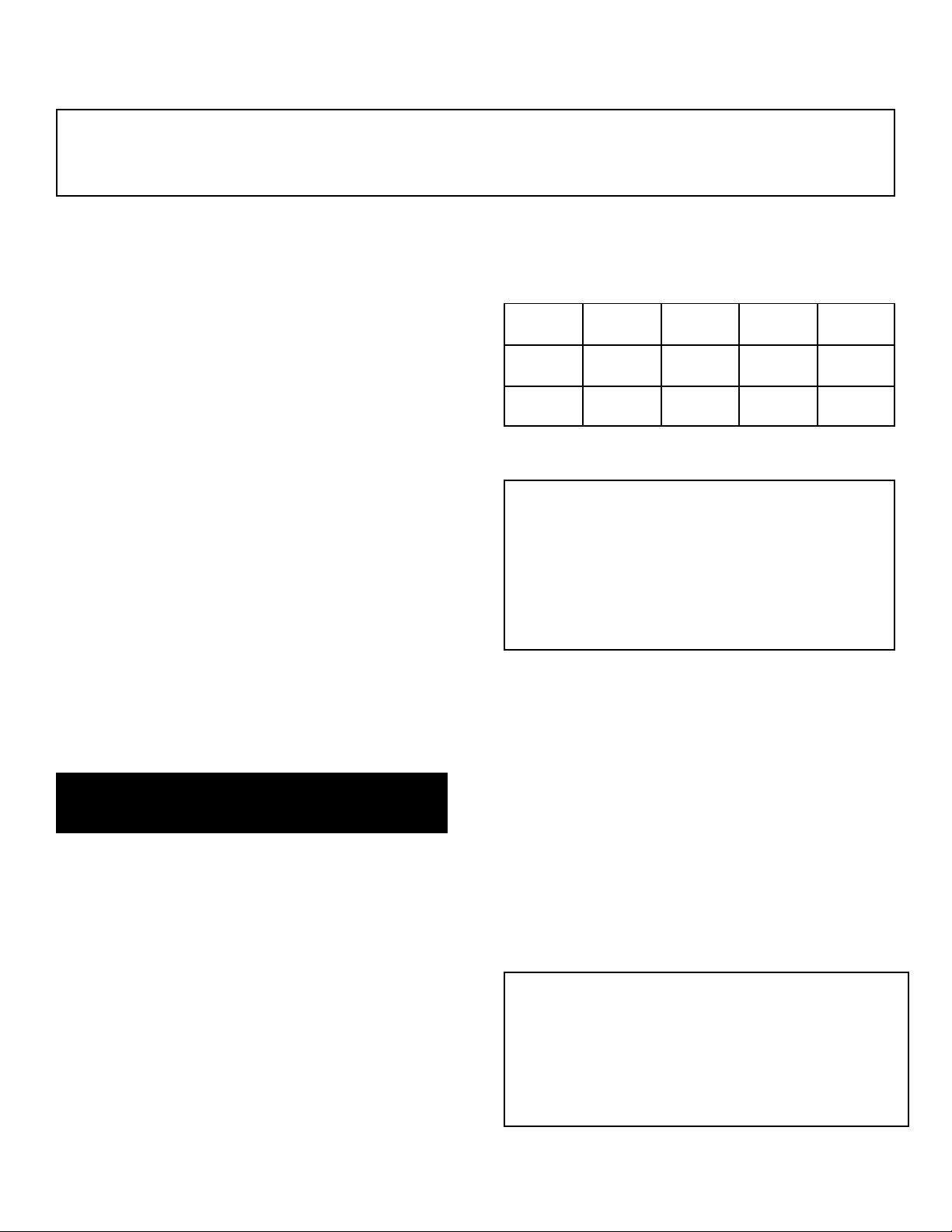
1.1.1 Model Number and Dimensions
MODEL
WIDTH
mm (in.)
DEPTH
mm (in,)
HEIGHT
mm (in.)
WEIGHT
Kg (lbs)
HY-12GF
815
(32.06)
1025
(40.4)
1590
(62.6)
256 (565)
HY-24GF
815
(32.06)
1025
(40.4)
1853
(73.37)
512
(1130)
1.1.2 Siting and Clearances
CAUTION
DO NOT INSTALL THIS UNIT SO RIGHT SIDE VENTS
ARE BLOCKED OR WITHIN 300 mm OF
A HEAT
SOURCE SUCH AS BRAISING PAN, DEEP FRYER,
CHAR BROILER OR KETTLE.
LEVEL THE UNIT FRONT TO BACK
OR PITCH IT
SLIGHTLY TO THE REAR TO AVOID DRAINAGE
PROBLEMS.
The HY-12GF(CE) steamer is suitable for
installation in combustible and noncombustible
locations. Minimum installation clearances are:
Right Side 300 mm (12 inches)
Left Side 0 mm (0 inches)
Rear of Flue 150 mm (6 inches)
The steamer requires 600 mm (24 inches)
clearance on the right side for service.
Allow minimum vertical clearance of 750 mm (30
inches) between the top edge of the flue outlet
and any overlying surface.
1.1.3 Ventilation
CAUTION
THE APPLIANCE FLUE DISCHARGES VERTICALLY
FROM THE TOP OF THE UNIT. IT MUST NOT BE
DIRECTLY CONNECTED TO ANY FLUE, MECHANICAL
EXTRACTION SYSTEM, OR DUCTS LEADING TO
OUTSIDE THE BUILDING. THE UNIT IS BEST
DISCHARGED UNDER AN OPEN CANOPY WHICH
CONNECTS WITH A VENTILATING SYSTEM
.
OM/SM-HY-12GF(CE) & HY-24GF(CE) 5
OM/SM-HY-12GF(CE) & HY-24GF(CE)
For multiple installations the requirements for
individual appliances should be added together. (See
table, page 5). Installation must comply withlocal
and/or national regulations and a competent installer
must be employed. Recommendations for
ventilation for catering appliances are given in BS
5440:2, and are shown in the table at right.
1.2 Electrical Supply Connection
The unit is designed for connection to fixed wiring. A
suitably rated isolating switch with contact separation
of at least 3 mm on both poles must be fitted to the
installation.
Wiring must be executed in accordance
with the regulations listed in this manual.
Equipment
Required Ventilation Rate
m³/min ft³/m
Units Type Range 17 600
Pastry Oven 17 600
Fryer 26 900
Grill 17 600
Steak Grill 26 900
Boiling Pan 17 600
Steamer 17 600
Sterilizing Sink 14 500
Bains Marie 11 400
Tea/Coffee Machine 8.5 - 14 300 - 500
6 OM/SM-HY-12GF(CE) & HY-24GF(CE)
OM/SM-HY-12GF(CE) & HY-24GF(CE)
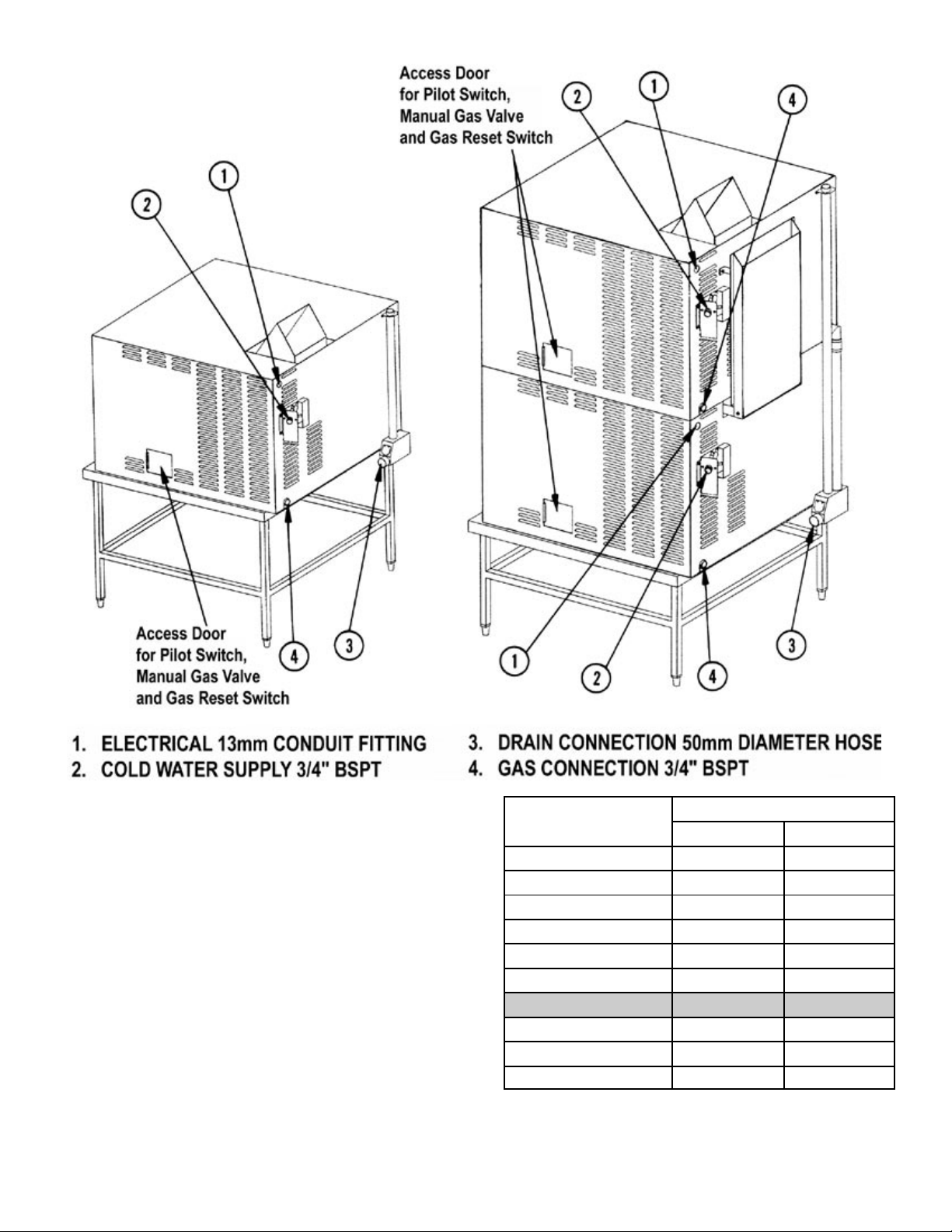
Cable entry is at the top rear right side of the appliance
for model HY-12GF(CE). There are two cable entries on
model HY-24GF(CE), at the rear right side of each
cavity. Access is gained as described in the Operator
and Service Manuals for this appliance.
Provide 230 Volt, 50 Hz, Single Phase, 15 Ampere
service. Maximum load is 2½ Amps. The electrical
schematic is located in the service compartment and
in this manual.
WARNING
THIS APPLIANCE MUST BE EARTHED.
1.3 Gas Supply Connection
Incoming service must be of sufficient size to supply
full rate without excessive pressure drop. A gas
meter is connected to the service pipe by the Gas
Supplier. Any existing meter should be checked out
by the Gas Supplier to ensure that it has adequate
capacity to provide the required rate of gas to the
steamer, in addition to any other installed equipment.
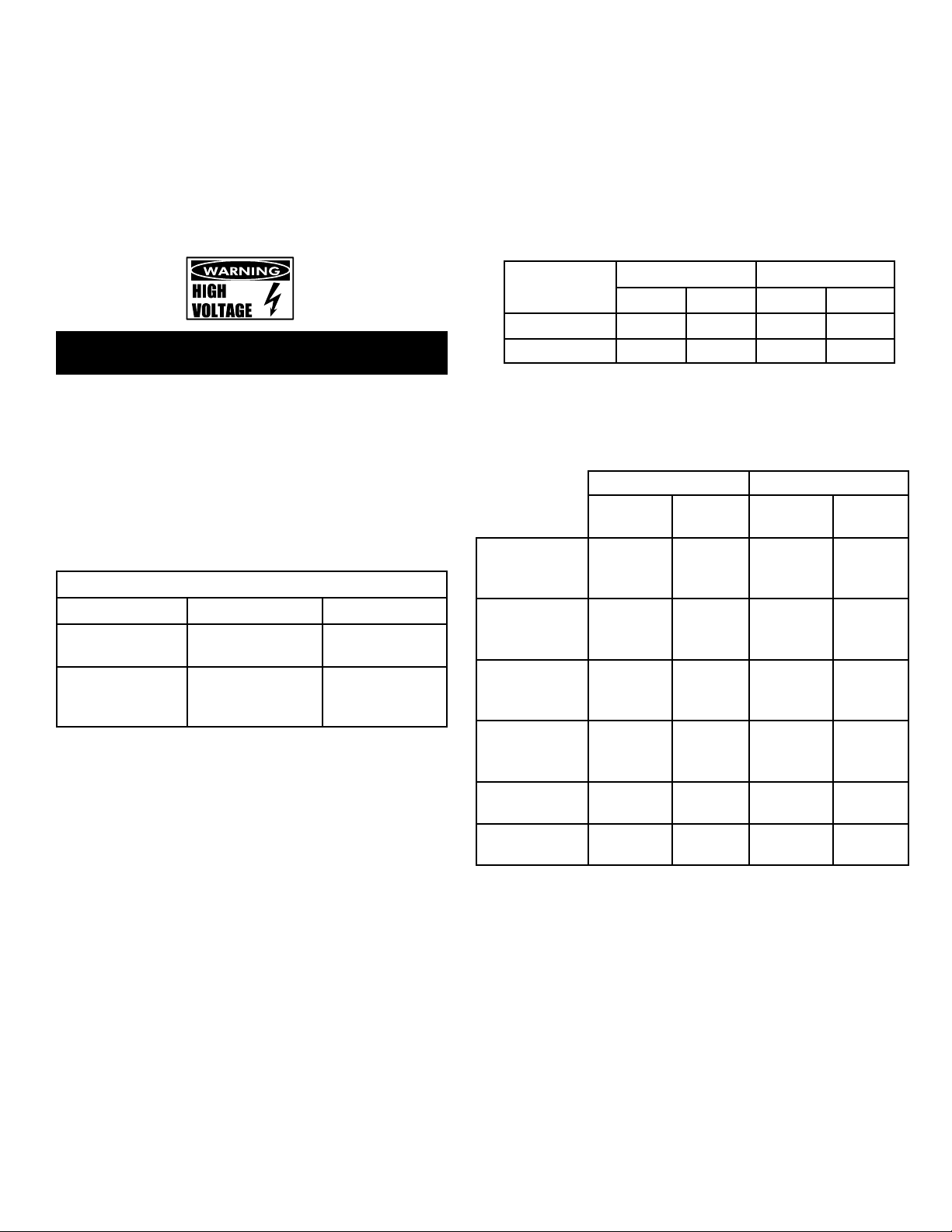
GAS INPUT RATE BTU/HR AND KW
Natural Gas Propane Gas
HY-12GF
150130 BTU/hr
44 KW
150130 BTU/hr
44 KW
HY-24GF
2 x 150130
BTU/hr
2 x 44 KW
2 x 150130
BTU/hr
2 x 44 KW
Installation pipe work must be fitted in accordance
with IGE/UP/2.
The appliance governor is suitable for both natural
and propane gas without conversion. The governor
is incorporated in the gas control valve, which is
inside the control cabinet.
Connection to the gas supply can be completed with
¾” BSPT pipe. Although the immediate connection
to the appliance is ¾” BSPT, gas supply piping must
be large enough to provide 160,000 BTU/hour.
Minimum supply pressure is 20 mBar for natural gas,
or 37 mBar for propane gas.
An isolating cock must be located close to the
appliance to allow shut down in an emergency, or for
servicing. The installation must be tested for gas
soundness and purged as specified in IGE/UP/1.
For the part of the integral gas supply downstream
from the gas valve, leak detection spray or some
solution may be used with the burners lit.
1.3.1 Gas Pressure Adjustment
Gas pressure has been set at the factory but
should be checked by connecting a manometer
to the pressure tap on the burner manifold. The
adjusted gas pressures are shown in the table
below.
Model
Natural Gas Propane Gas
mBar WCI mBar WCI
HY-12GF(CE) 7.75 3.1 25 10
HY-24GF(CE) 7.75 3.1 25 10
If necessary, the gas pressure may be
readjusted as described in Section 3..
1.3.2 Injector Diameters
Natural Gas Propane Gas
Injector
Dia. (mm)
No. of
Injectors
Injector
Dia. (mm)
No. of
Injectors
HY-12GF(CE)
Main Burner
(high fire)
1.18 30 0.70 30
HY-24GF(CE)
Main Burner
(high fire)
1.18 30 x 2 0.70 30 x 2
HY-12GF(CE)
Igniter Burner
(low fire)
0.64
1 0.41 1
HY-24GF(CE)
Igniter Burner
(low fire)
0.64 1 x 2 0.41 1 x 2
HY-12GF(CE)
Pilot Burner
0.60
1 0.36 1
HY-24GF(CE)
Pilot Burner
0.6 1 x 2 0.36 1 x 2
1.3.3 Burner Air Adjustment
The unit is equipped with fixed aeration type
burners which have no provision for air inlet
adjustment.
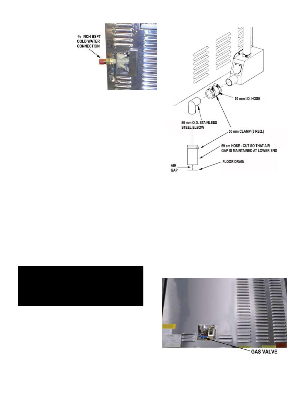
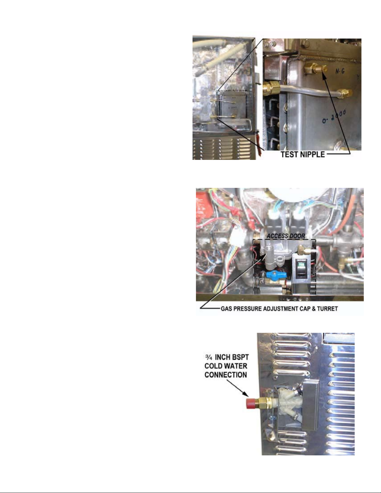
1.4 Water Supply Connection
Water entry is at the rear right side of the appliance.
There are two water entries on the HY-24GF(CE).
The steamer is fitted for a ¾ inch BSPT cold water
connection. The water supply must be provided at a
OM/SM-HY-12GF(CE) & HY-24GF(CE) 7
OM/SM-HY-12GF(CE) & HY-24GF(CE)
Drain Connection with Drain Box
rate of not less than
7.6 liters (tw
o
gallons) per minute.
Pressure must
be
2.0 to 4.0 Bar (30 to
60 PS
I) maximum.
Water qualit
y
minimums requir
e
totally dissolve
d
solids (T.D.S.) of
30
parts per million
maximum, and a
water pH of 7.0 or greater. If the available wate
r
supply fails to meet these requirements, water
treatmen
t equipment must be provided to ensure
steamer reliability and operating life
.
Install a WRAS approved double-check valve or an
equally effective backflow preventive device in the
incoming cold water line at the point of connnection(s)
to the steamer and in compliance with all local
plumbing codes. This installation must be per WRASIRN R160 Schedule 2-15(1). For units with the dual
water connection option, a double-check valve shall
be installed on each water line.
1.
5 Drain Connection
The unit must be leveled front to back or pitched
slightly to the rear (one to two degrees)
by
adjustment of the bullet feet on the cabinet base. All
units are shipped from the factory with a drain box
and vent pipe.
The drain box and vent pipe provide the necessary
air gap when properly installed. The illustrations
at
right shows proper installation of drain lines.
Leave
a air gap to any building drain. Do NOT
create any water traps in the drain line.
A trap could
cause pressure to build up in the cavity durin
g
steaming and cause the door gasket to leak
.
WARNING
VARIATION FROM THESE INSTRUCTIONS CAN
CREA
TE A HAZARD.
DO NOT USE PLASTIC PIPING — DRAIN MUST
WITHSTAND VERY HOT WATER.
1.
6 Initial Start-Up
After the HY-12GF(CE) Steamer has been installed, test
it to be sure that it is operating correctly.
1. Remove all literature and packing materials from
the interior and exterior of the unit.
2. Make sure the water supply line is open.
3. Make sure the gas supply line is open and that
the gas shut-off valve in the unit is in the OPEN
position. This valve is located behind an access
panel on the right side of the uni
t
4. Turn on electrical service to the unit. The unit
will not operate without electrical power. Do not
try to operate the un
it during a power failure.
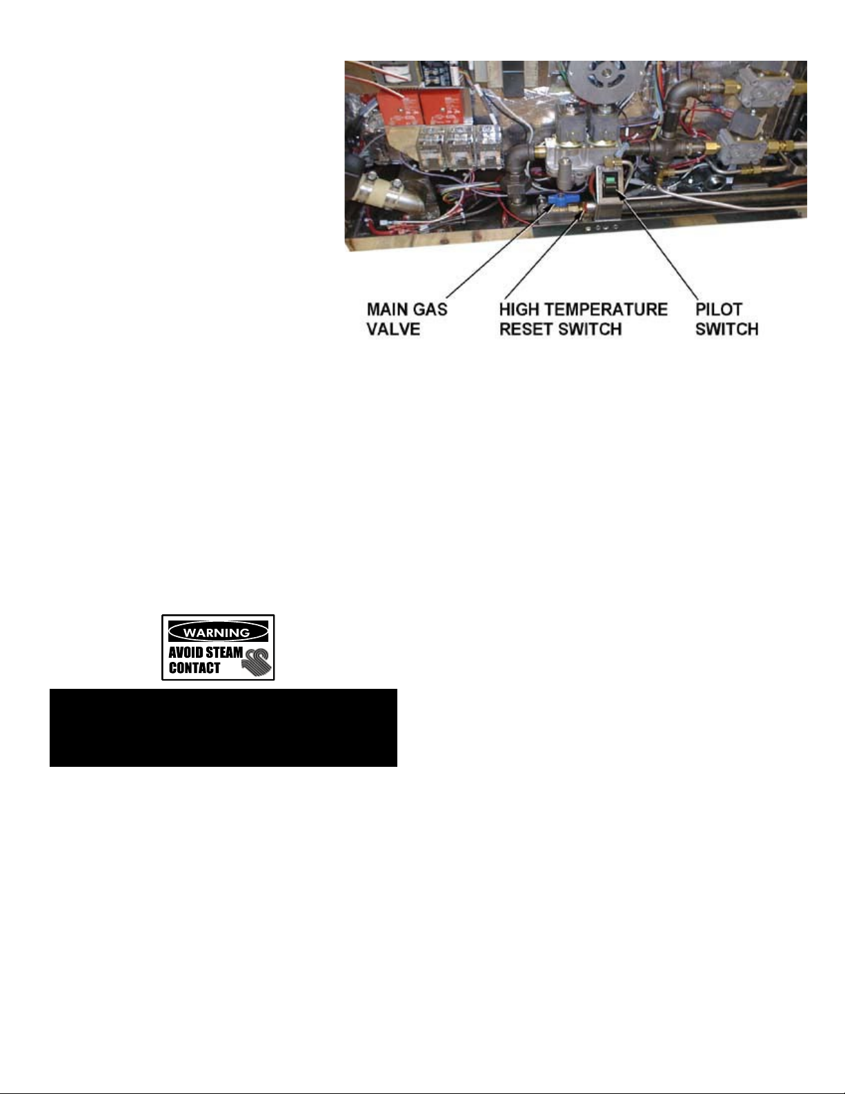
5. The steamer will not operate until the pilot burner
has been ignited. To light the pilot burner
,
ac
tivate the pilot switch next to the main gas
valve. (See photo below)
. When the ignition
sequence is successful a green light on the
electrical panel will glow.
8 OM/SM-HY-12GF(CE) & HY-24GF(CE)
OM/SM-HY-12GF(CE) & HY-24GF(CE)
6. The “trial for ignition” period is roughly
90 seconds. If the pilot burner does
not light within 90 seconds, the system
automatically stops gas flow to the pilot
burner and lights the Lockout neon on
the front control panel. If this happens,
turn off the pilot switch, push the Gas
Reset switch, and repeat the trial for
ignition. During the first start-up, the
pilot may require several trials for
ignition to bleed air from the piping.
Subsequent start-ups should only need
about five seconds to achieve pilot
ignition. NOTE:See Automatic Pilot
Operation at the end of this section.
7. Once the pilot flame has been
established (the green light on the
electrical panel is on), press the “ON”
switch for the desired steamer cavity.
The steam generator will fill with water.
NOTE:The door MUST be closed for the main
(high) heater to work.
8. When the steam generator has filled with water,
the main and low burners will automatically light.
The READY light should come on within 10
minutes, to show that the water has reached its
standby temperature. When the READY light is
on, the operator may take any of the following
steps:
a. Set the timer to the desired time for timed
steaming.
WARNING
WHEN YOU OPEN THE DOOR, STAY AWAY FROM
STEAM COMING OUT OF THE UNIT. THE STEAM
CAN CAUSE BURNS.
b. Turn the timer knob to the manual ON
position for continuous steam.
c. Let the unit wait at standby temperature. The
steam generator is equipped with a high-limit
thermostat which will trip if the liquid level
probe fails.
9. If this happens, the High Temperature neon on
the front control panel will glow and trip a reset
switch. The Reset Switch must be pressed to
re-start steam generation. This switch is located
next to the pilot switch (towards the rear of the
unit) and can be reached through the access
door on the right side of the unit.
10. To shut down the unit, turn the ON switch to the
OFF position. The steam generator will
automatically drain. You may also switch OFF
the pilot switch to conserve energy
11. If your steamer works as described, it is
functioning correctly and is ready for use.
Automatic Pilot Operation
Once the pilot burner has been lit, it essentially
functions as a standing pilot. When the pilot switch
is on, if the pilot is accidentally extinguished (by a
very strong gust of wind or the like), it will re-ignite
automatically. The unit will shut off completely for a
few seconds while the pilot is re-ignited. The unit will
then come back on and resume operation in the
mode and at the (running) timer value existing just
prior to shutdown. The pilot switch may be turned off
during “off hours” to conserve energy.
If the pilot burner ever fails to re-ignite automatically
within 90 seconds, after the unit has been running,
the Gas Lockout neon on the front control panel will
light. Wait five minutes and push the Gas Reset
switch to reignite the pilot. Should ignition problems
persist, contact your authorized Groen Service
Agency.
1.7 Setting the Gas Pressure
1. During commissioning, a gas pressure check is
essential. Connect a suitable pressure gauge to
the gas manifold to perform this test. The
pressure gauge should be connected to the test
nipple (See photograph at right).
OM/SM-HY-12GF(CE) & HY-24GF(CE) 9
OM/SM-HY-12GF(CE) & HY-24GF(CE)
Adjust Gas Pressure by Turning the Screw inside the
Gas Pressure Adjustment Turret.
To test pressure, attach a pressure gauge to the test
nipple on the gas manifold.
2. Turn the main gas and electricity supply on.
3. Light the burners as described in Paragraph 1.6
above.
4. Manifold gas pressure should be as noted in
Section 1.3.1 of the manual. If adjustment is
necessary, follow steps below.
5. Remove the governor cap screw on the gas
control valve to gain access to the screw inside
the turret. (See photograph).
6. The governor is suitable for both natural and
propane gas.
7. Turn the screw inside the turret clockwise to
increase the pressure, anti-clockwise to reduce
it. Check the burner pressure again after 15
minutes operation, and adjust if necessary.
8. Disconnect the pressure gauge from the test
point. Reseal the test point and test for gas
soundness.
9. Replace governor cap screw, and replace
control box panel and lid.
NOTE
: For operation at high altitudes (1000 meters and
above) consult the Groen Food Service
Engineering Department.
1.8 Instructions to User
IMPORTANT: After installing and commissioning the
appliance, the User’s Instructions should be handed
to the user or purchaser. Ensure that the
instructions for lighting, turning off, correct use and
cleaning are properly understood. Emphasize the
location of the main gas isolating valve and
demonstrate the emergency shut down procedure.

10 OM/SM-HY-12GF(CE) & HY-24GF(CE)
OM/SM-HY-12GF(CE) & HY-24GF(CE)
2. Servicing and Conversion
CAUTION
BEFORE ATTEMPTING ANY SERVICING, ENSURE THAT THE ISOLATING COCK IS TURNED OFF AND CANNOT
BE INADVERTENTLY TURNED ON. CHECK THAT THE ELECTRICITY SUPPLY IS DISCONNECTED.
AFTER ANY MAINTENANCE TASK CHECK THE APPLIANCE TO ENSURE THAT IT PERFORMS CORRECTLY AND
CARRY OUT ANY NEEDED ADJUSTMENTS AS DETAILED IN SECTION 1.
AFTER CARRYING OUT ANY SERVICING OR EXCHANGE OF GAS CARRYING COMPONENTS ALWAYS CHECK FOR
GAS SOUNDNESS.
Conversion
To change from natural gas to propane gas or vice
versa, change the following:
• Burner injectors (high fire orifices)
• Rimner Tube Injector (low fire orifice)
• Pilot orifice
• Pressure setting
• Data Plate
The governor spring does not need to be changed —
only the pressure setting.
After Servicing
1. Test for gas soundness as specified in IGE/UP1
as appropriate after any gas connection has
been disturbed.
2. Check for correct operation (see Commissioning
of Appliance)
2.1 Assembly/Disassembly Procedures
GENERAL INFORMATION
The procedures which follow are based on having full
access to the steamer on all four sides. If the steamer is
installed between other appliances and there is not
enough room on the sides for access, it must be puled
out from its position. Exercise care when moving the
steamer to avoid stress or pull on electrical, water and
gas connections.
2.1.1 Right Side Panel (Louvered) — Removal
P/N 123196
1.
With a flat blade screwdriver, remove the two
10-32 screws on the lower edge of the panel.
The panel is retained to the steamer by an
interlocking guide track on the top edge and
three spring-like clips at the rear edge.
2. Once the screws are removed, SLIDE the panel
toward the front of the appliance with a lifting
motion. Do not attempt to pry the panel. Once
the panel is clear of the rear clips, it may be lifted
off of the top rack.
ASSEMBLY TIP: When replacing the panel, press the
rear edge inward so that all three clips are retained by
the back flange. Make sure that the holes in the panel
align with the two tapped holes in the steamer so that
replacing the screws will be easy and will not damage the
threads.
2.1.2 Left Side Cover — Removal
Left P/N 123197
Under normal conditions, the left side cover should never
have to be removed, since there are no operational or
replacement parts to be accessed. The single exception
occurs when the door has been reversed so that the
handle is on the left and the Door Interlock Switch
requires replacement. The door switches for both door
positions are installed at the factory, so there is no need
to have access to them if the door is to be reversed.
1. If the left side cover is to be removed because of
a faulty door switch, remove the right side panel
first. Using a 7mm nut driver and the flat blade
screwdriver, remove the retaining clip and the
two screws on the lower edge of the left side
cover. The assembly may then be slid forward.
Once clear of the retaining clip, it may be lifted
off.
ASSEMBLY TIP: When replacing the left cover
assembly, be sure that the retaining clip is replaced and
screwed down tightly.
2.1.3 Water Inlet Valve — Three Way
P/N 090827
1. Turn off power and water supply to the steamer.
2. Remove the water supply hose connection on
the rear of the steamer.
3. Remove the right side panel, as described in
Paragraph 2.1.1, above.

OM/SM-HY-12GF(CE) & HY-24GF(CE) 11
4. Remove the screws holding the water inlet valve
bracket, and pull the bracket with the valve a few
cm away from the body of the appliance.
5. The water inlet valve branches to three individual
solenoid-activated valves within its housing.
These are connected with the following three
sets of wires:
Steam Generator Fill . . . . . . . . Yellow & Orange
Steam Generator Clean . . . . . . . . Violet & Gray
Condensate Spray . . . . . . . . . . . . Green & Blue
6. Using a 7 mm nut driver, loosen the hose
clamps on the inlet valve.
7. Slide the hose clamps down the hose until
needed for reassembly. Loosen and remove the
hoses from the valve with a gentle rocking
motion.
8. Remove the bracket from the valve and lower
the valve
WITH THE WIRES STILL ATTACHED.
9. Carefully unplug the connectors one at a time
and attach to the new valve.
10. To install a new valve, reverse the procedures.
First install the six wires (three sets) as listed in
item 5, above. Make certain that the valve is
NOT installed upside down.
11. Attach the valve to its bracket with the two
screws and return it to its position.
12. Re-attach the hoses to the valve. Slide the
hoses all the way so that the end of the hose is
flush against the face of the valve.
IMPORTANT: Be sure the correct hose is connected to
the corresponding outlet.
13. Slide the clamps back into position around the
end of the hoses and tighten the clamps.
CAUTION
DO NOT OVER-TIGHTEN THE CLAMPS. OVERTIGHTENING CAN DAMAGE THE VALVE.
2.1.4 Adjustable Legs
P/N 042505
1. Each leg is provided with a screw-type support
post. These may be extended or retracted by
turning them with a wrench or Channel Lock. Be
sure that all four legs are in tight contact with the
floor for proper steamer support.
2. If damaged, the posts may be replaced by
tapping out the threaded fitting (on the opposite
side of the leg) which is friction-held in each leg.
The stainless steel leg and threaded fitting are a
single assembly.
2.1.5 Main Gas Valve and Gas Pressure
Adjustment P/N 122158
1. Disconnect power to the steamer.
2. Remove the right side panel, as described in
Paragraph 2.1.1, above.
3. Turn the manual gas valve to the closed
position. Disconnect the wire to the solenoids.
4. Note the color and position of the two connectors
for assembly.
5. Remove all aluminum tubing from the piping
assembly using an open-ended wrench. Be
careful not to move the aluminum tubing
excessively, or to bend it.
6.
With a pipe wrench or Channel Lock, open the
pipe union on the left side of the main gas valve
and the right side near the solenoid valves.
Remove the assembly.
7. From both sides of the main gas valve, using a
Channel Lock, turn to remove the nipples.
Support the valve with a vise or Channel
Lock/pipe wrench.
To Assemble:
8. Screw in and tighten the nipples into both sides
of the main gas valve using approved gas pipe
sealant.

12 OM/SM-HY-12GF(CE) & HY-24GF(CE)
9. Using a pipe wrench or Channel Lock attach the
union and tighten.
10. Attach all aluminum tubing and tighten with an
open-ended wrench.
11. Plug in the two connectors to the main gas valve:
2.1.6 Gas Solenoid Valve
P/N 122120
The gas solenoid valves must be removed as an
assembly along with the regulators, using the following
procedures:
1. Turn off the gas supply and power to the
steamer.
2. Disconnect wires from the main gas (Step 4,
Paragraph 2.1.5) and from the gas solenoid
valves.
3. From the front of the steamer, using a Channel
Lock wrench, loosen and disconnect the pipe
union which connects the assembly to the main
gas valve.
4. From the left side (or back) of the steamer, use
an open-ended wrench to loosen and disconnect
the compression fittings which connect the 9.5
mm aluminum tubing, from the inner and outer
manifolds.
5. From the left side (or back) of the steamer, use
an open ended wrench to loosen and disconnect
the compression fittings which connect the 9.5
mm aluminum tubing, from the inner and outer
manifolds.
6. The entire assembly of both regulators and the
gas solenoid valves for the upper and lower
steam generators may be removed as an
integrated unit.
7. Remove the failed gas solenoid valve.
To Reinstall:
8. Clean pipe threads and apply compound to all
joints being connected.
9. Install the new gas solenoid valve.
10. Slide the assembly into the steamer and align
the tee fitting with the pipe union. Align the gas
valves with their respective aluminum tubing.
11. Connect the pipe union using a Channel Lock
wrench.
12. Using an open-ended wrench, connect the 9.5
mm aluminum tubing to the inner and lower
steam generator manifold.
13. Using an open-ended wrench, connect the 12.7
mm aluminum tubing from the inner and outer
steam generator manifolds.
14. Reconnect the wires to the correct valve.
2.1.7 Igniter Module
P/N 154059
1. Shut off power and gas to the steamer.
2. Remove the cover to the electrical compartment.

OM/SM-HY-12GF(CE) & HY-24GF(CE) 13
OM/SM-HY-12GF(CE) & HY-24GF(CE)
3. The igniter module is located next to the motor.
4. Note or tag the wires for reinstallation before
unplugging. Carefully disconnect the seven
push terminals from the igniter module. be
careful not to pull the terminal by the wire. Use
needle nose plers to grip onto the terminal itself.
5. Use a nut driver (preferably with a magnetic tip)
to remove the two 6-32 screws.
6.
To Install:
7.
8. When all screws are in place, tighten them
one at a time.
9. Plug in each of the six terminals. Double check
to ensure that they are correct.
2.1.8 Pilot Switch (SW3) Removal
P/N 087951
1. Shut off the power supply. Disconnect the four
color coded wires from the switch assembly.
Remove the two retaining screws which attach
the switch bracket to the lower frame rail of the
steamer.
2. The switch snaps into the bracket where it is
retained by plastic tabs on the top and bottom.
To remove the switch from the bracket, press in
on both tabs at the same time and slide the
switch out of the bracket hole.
To replace the switch
3. Insert the new switch into the bracket hole until
its tabs clear the hole and snap into position.
4. Reattach the wires to the switch.
5. Replace the switch bracket with two screws.
2.1.9 Pilot Burner Replacement/Current Check/
Adjustment - Pilot Flame Sensor
Replacement
P/N 102258 (Natural) P/N 106610 (Propane)
P/N 003328 Flame Sensor
1. Turn off the main gas and power supply.
2. Remove the front cover.
3. Remove the right side panel as described in
Paragraph 2.1.1.
4. Turn the manual gas valve to the OFF position.
Place pilot switch SW3 in the OFF position.
5. Disconnect the pilot line from the pilot burner.
6. Disconnect the “spark” lead from the pilot
burner.
7. Remove the flame sensor from the flame sensor
bracket.
8. Remove the pilot burner.
Installation:
9. Connect the pilot line to the pilot burner.
10. Connect the “spark” lead to the pilot burner. Be
sure to route the lead around the outside of the
gas lines.
11. Replace the flame sensor on the flame sensor
bracket.
12. Apply anti-seize lubricant to mounting head
screw threads. Install the pilot burner and flame
sensor assembly, and tighten the screws.
NOTE
: Route the “spark” lead and flame sensor wire
away from the manifold to prevent improper
operation.
13. Turn manual gas valve to the ON position.
14. Connect unit to the branch circuit and turn on the
main gas supply.
15. Place pilot switch SW3 in the ON position.
Check for gas soundness.
Remove the igniter module.
Position the new igniter against the back wall
or mounting bracket of the electrical compartment
Place a hex head screw in the nut driver and start
each of the two screws.

14 OM/SM-HY-12GF(CE) & HY-24GF(CE)
Pilot Flame Current Check
WARNING
WHEN STEAMER POWER IS TURNED ON, THERE IS
HIGH VOLTAGE PRESENT IN THE ELECTRICAL
COMPONENTS COMPARTMENT. BE SURE THAT
STEAMER IS DISCONNECTED FROM BRANCH
CIRCUIT BEFORE PERFORMING ANY REPAIRS.
1. Turn off steamer power.
2. Disconnect the ground (green) wire from the
igniter module.
3. Connect a DC micrometer between the igniter
ground terminal and the disconnected green
wire.
WARNING
DO NOT ATTEMPT TO LIGHT THE PILOT BURNER
WITH A FLAME.
4. Ignite the pilot. The micrometer should read 3
microamps minimum.
• If current reading is correct, replace the
igniter module (see 2. 1. 7).
* If current reading is below 3 microamps,
continually check the Flame Rectification
Circuit (large orange wire, spark electrode,
pilot burner hood, and ground connections).
If necessary, tighten ground connections
and/or replace defective component(s).
5. Check for moisture around the pilot burner, and
for corrosion on the electrode and the pilot
burner hood. If necessary, remove moisture with
a dry, clean cloth. If hood and/or electrode are
excessively corroded, replace pilot burner
assembly.
2.1.10 Steam Generator Probes (High and Low
Water) P/N 070178
NOTE
: There are two probes for each steam generator.
1. Shut off power to the steamer.
2.
With an 8 mm nut driver LOOSEN, but do not
remove the nuts holding the wire(s) on the probe
terminal(s).
3. The wires are connected to wire fork terminals.
These will "snap" on and off the terminal post.
Unsnap them by gently pulling on the terminal.
4. Using a 21mm open ended wrench, turn the
probe counter-clockwise to remove. Clean or
replace water level probes.
To Install:
5. Apply high temperature pipe compound to the
probe and screw it in by hand. Using a 21mm
open ended wrench, tighten the probe into the
fitting.
6. Replace the wire(s) to the probes by snapping
the fork terminals around the terminal post.
Using an 8 mm nut driver, tighten the terminal
nut.
NOTE
: If two probes are to be replaced, either replace
them one at a time or note the color of the wires
attached to the probes. Do not mix them up.
2.1.11 Water Level Control Board
P/N 106258
1. Shut off electrical power to the steamer.
2. Remove the side panel screws and slide panel
away from steamer.
3. Remove two kep nuts and star washers securing
main control board mounting bracket. Lay main
control board to the side.
4. Unplug the three terminals on the side of the
water level control board: "C", "Low" and "High".
Note wire colors and terminal positions.
5. Remove four nuts holding the board to the
steamer frame and remove board.
6. Unplug the multi-conductor plug on the opposite
side of the board.
To Install:
7. Plug in the multi-conductor plug on the bottom of
the board. Make sure the plug is firmly and
properly seated.
8. Place the water level control board over the
mounting studs and fasten with four nuts.
9. Plug in the three terminals on the side of the
board, making sure to plug the low wire into the

OM/SM-HY-12GF(CE) & HY-24GF(CE) 15
OM/SM-HY-12GF(CE) & HY-24GF(CE)
low terminal, the high wire into the high
terminal and the "
C" into the "C" terminal.
10. Install two star washers and kep nuts to secure
main control board mounting bracket.
11. Install the side cover and fasten with screws.
2.1.12 Steam Generator Gas Jet Manifold
P/N 106224
1. Shut-off power and gas to the steamer.
2. Remove the right side panel.
3. Turn manual gas valve to the closed position.
4. Remove the three aluminum tubes connected to
the manifold. Disconnect the tubes using an
open ended wrench.
5. Remove the two screws from the pilot mounting
bracket. Remove pilot from the gas manifold.
6. Using a nutrunner or socket wrench remove the
two top and two bottom bolts which hold the
manifold to the steam generator manifold
mounting bracket.
7. Remove the burner manifold from the appliance.
8. Remove the flame retention springs and
injectors as required.
To Reassemble
:
9. Replace the injectors and retention springs.
Ensure a suitable gas sealant is used on the
threads of the injectors to ensure a gas tight
seal.
10. Fit the burner manifold to the steam generator
manifold mounting bracket.
11. Reinstall and tighten the aluminum tubes to the
burner manifold.
NOTE
: Ensure all gas connections are sound before
continuing.
2.1.13 Steam Generator Drain Valve
P/N 071234
1. Turn off power and allow steamer to drain
completely. Remove back cover panel and
loosen clamps or spring.
2. Using a 7mm nut driver or spring clamp pliers,
disconnect both ends of the drain hose from the
spray box and the steam generator.
3. Unplug and disconnect the valve electrical wires.
Remove the 10-32 kep nuts holding the valve to
the plate. Remove the valve from the threaded
studs. Then remove silicone hose from the
valve.
4. Inspect the silicone hose for any damage or lime
buildup. Clean or replace hose if required.
5. Attach new drain valve to valve bracket if bracket
applicable. Pull silicone hose through drain valve
and loosely install hose clamps over both ends
of the hose. Be sure that the silicone hose is
properly aligned and does not have any kinks,
bends or twists in it.
6. Position the valve over the valve mounting
threaded studs, and connect both ends of the
hose to drain box or drain tube and steam
generator.
7. Position the clamps so that the worm screw may
be easily tightened. Using a 7mm nut driver,
tighten both hose clamps. Be careful not to overtighten clamps since they could cut the hose. If
using spring clamps, use pliers to position them.
8. Install and tighten the valve mounting 10-32 cap
nuts.
9. Plug electrical leads into wiring harness.
Test: Operate the steamer and allow steam generator
to fill. Check for leaks and observe if the drain
valve fully closes. Turn off the steamer and
make sure that the drain valve opens and the
steam generator drains. Install back cover.
2.1.14 Drain Box Spray Nozzle
P/N 106445
Disassemble
1. Turn off power to the steamer. Turn off the water
supply to the steamer. Remove the water supply
hose connection on the rear of the steamer
2. Remove the two screws on the right side of the
water inlet panel. Pull the water inlet valve
mounting plate away from the steamer and slide
it free.
3. Loosen the hose clamp nearest the end of the
black hose. Pull the hose off from valve nipple.
 Loading...