

Groen HY-12GF Installation Manual
���� IMPORTANT INFORMATION
IMPORTANT INFORMATION �
IMPORTANT INFORMATION IMPORTANT INFORMATION
OPERATOR MANUAL
OPERATOR MANUAL OM-HY-12G/24G
Part Number 142253 Rev. C
Part Number 142253 DOMESTIC
� KEEP FOR OPERATOR
KEEP FOR OPERATOR �
��
KEEP FOR OPERATOR KEEP FOR OPERATOR
� IMPORTANT INFORMATION
IMPORTANT INFORMATION �
��
IMPORTANT INFORMATION IMPORTANT INFORMATION
�
��
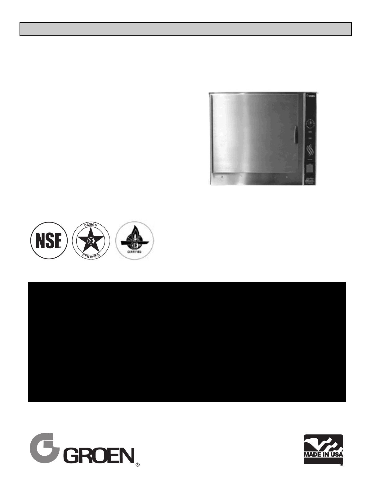
Model: HY-12GF, HY-24GF
HyCapacity HyPerSteam™
Atmospheric Convection
Steamer
Self-Contained
Gas Heated
® ®
THIS MANUAL MUST BE RETAINED FOR FUTURE REFERENCE. READ, UNDERSTAND
AND FOLLOW THE INSTRUCTIONS AND WARNINGS CONTAINED IN THIS MANUAL.
FOR YOUR SAFETY
DO NOT STORE OR USE GASOLINE OR OTHER FLAMMABLE VAPORS AND LIQUIDS IN
THE VICINITY OF THIS OR ANY OTHER APPLIANCE
POST IN A PROMINENT LOCATION
INSTRUCTIONS TO BE FOLLOWED IN THE EVENT USER SMELLS GAS. THIS
INFORMATION SHALL BE OBTAINED BY CONSULTING YOUR LOCAL GAS SUPPLIER. AS
A MINIMUM, TURN OFF THE GAS AND CALL YOUR GAS COMPANY AND YOUR
AUTHORIZED SERVICE AGENT. EVACUATE ALL PERSONNEL FROM THE AREA.
WARNING: IMPROPER INSTALLATION, ADJUSTMENT, ALTERATION, SERVICE OR
MAINTENANCE CAN CAUSE PROPERTY DAMAGE, INJURY OR DEATH. READ THE
INSTALLATION, OPERATING AND MAINTENANCE INSTRUCTIONS THOROUGHLY BEFORE
INSTALLING OR SERVICING THIS EQUIPMENT.
.

OM-HY-12G/24G
OM-HY-12G/24G
IMPORTANT — READ FIRST — IMPORTANT
WARNING: THE UNIT MUST BE INSTALLED BY PERSONNEL QUALIFIED TO WORK WITH
ELECTRICITY AND PLUMBING. IMPROPER INSTALLATION CAN CAUSE INJURY TO
PERSONNEL AND/OR DAMAGE TO THE EQUIPMENT. THE UNIT MUST BE INSTALLED IN
ACCORDANCE WITH APPLICABLE CODES.
CAUTION: DO NOT INSTALL THE UNIT IN ANY WAY WHICH WILL BLOCK THE RIGHT SIDE VENTS, OR
WITHIN 12 INCHES OF A HEAT SOURCE SUCH AS A BRAISING PAN, DEEP FRYER, CHAR
BROILER OR KETTLE.
NOTICE: Level the unit front to back, or pitch it slightly to the rear, to avoid drainage problems.
CAUTION: DO NOT LOCATE THE CABINET DIRECTLY OVER A FLOOR DRAIN OR FLOOR SINK.
HUMIDITY OR WATER FROM A DRAIN WILL DAMAGE ELECTRICAL PARTS OF A UNIT.
WARNING: TO AVOID DAMAGE OR INJURY, FOLLOW THE WIRING DIAGRAM EXACTLY WHEN
CONNECTING A UNIT.
WARNING: DO NOT CONNECT THE DRAIN DIRECTLY TO A BUILDING DRAIN.
CAUTION: DO NOT USE PLASTIC PIPE. DRAIN MUST BE RATED FOR BOILING WATER.
WARNING: BLOCKING THE STEAM GENERATOR OR CAVITY DRAIN SCREEN MAY BE HAZARDOUS.
IMPORTANT: Improper drain connection will void warranty.
WARNING: WHEN YOU OPEN THE DOOR, STAY AWAY FROM STEAM COMING OUT OF THE UNIT.
STEAM CAN CAUSE BURNS.
WARNING: BEFORE CLEANING THE OUTSIDE OF THE STEAMER, DISCONNECT THE ELECTRIC
POWER SUPPLY. KEEP WATER AND CLEANING SOLUTIONS OUT OF CONTROLS AND
ELECTRICAL COMPONENTS. NEVER HOSE OR STEAM CLEAN ANY PART OF THE UNIT.
WARNING: ALLOW COOKING CHAMBERS TO COOL BEFORE CLEANING.
WARNING: CAREFULLY READ THE WARNINGS AND FOLLOW THE DIRECTIONS ON THE LABEL OF
EACH CLEANING AGENT.
USE SAFETY GLASSES AND RUBBER GLOVES AS
RECOMMENDED BY DELIMING AGENT MANUFACTURER.
WARNING: DO NOT MIX DE-LIMING AGENTS (ACID) AND DE-GREASERS (ALKALI) IN THE STEAM
GENERATOR OR ON THE COOKING CHAMBER WALLS.
WARNING: DO NOT PUT HANDS OR TOOLS INTO THE COOKING CHAMBER UNTIL THE FAN HAS
STOPPED TURNING.
WARNING: DO NOT OPERATE THE UNIT UNLESS THE REMOVABLE RIGHT SIDE PANELS HAVE BEEN
RETURNED TO THEIR PROPER LOCATIONS.
NOTICE: Do not use a cleaning or de-liming agent that contains any sulfamic acid or any chloride,
including hydrochloric acid. If the chloride content of any product is unclear, consult the
manufacturer.
WARNING: USE OF ANY REPLACEMENT PARTS OTHER THAN THOSE SUPPLIED BY GROEN OR
THEIR AUTHORIZED DISTRIBUTOR VOIDS ALL WARRANTIES AND CAN CAUSE BODILY
INJURY TO THE OPERATOR AND DAMAGE THE EQUIPMENT. SERVICE PERFORMED BY
OTHER THAN FACTORY-AUTHORIZED PERSONNEL WILL VOID ALL WARRANTIES.
WARNING: HIGH VOLTAGE EXISTS INSIDE CONTROL COMPARTMENTS. DISCONNECT FROM
BRANCH BEFORE SERVICING. FAILURE TO DO SO CAN RESULT IN SERIOUS INJURY OR
DEATH.
2

OM-HY-12G/24G
OM-HY-12G/24G
Table of Contents
IMPORTANT OPERATOR SAFETY WARNINGS . . . . . . . . . . . . . . . . . . . . . . . . . . . . . . . . . . 2
REFERENCES . . . . . . . . . . . . . . . . . . . . . . . . . . . . . . . . . . . . . . . . . . . . . . . . . . . . . . . . . . . . . 3
EQUIPMENT DESCRIPTION . . . . . . . . . . . . . . . . . . . . . . . . . . . . . . . . . . . . . . . . . . . . . . . . . . 4
WATER CONDITIONING . . . . . . . . . . . . . . . . . . . . . . . . . . . . . . . . . . . . . . . . . . . . . . . . . . . . . 4
INSTALLATION AND START-UP INSTRUCTIONS . . . . . . . . . . . . . . . . . . . . . . . . . . . . . . . . . 6
OPERATING INSTRUCTIONS . . . . . . . . . . . . . . . . . . . . . . . . . . . . . . . . . . . . . . . . . . . . . . . . 10
CLEANING . . . . . . . . . . . . . . . . . . . . . . . . . . . . . . . . . . . . . . . . . . . . . . . . . . . . . . . . . . . . . . . 13
MAINTENANCE . . . . . . . . . . . . . . . . . . . . . . . . . . . . . . . . . . . . . . . . . . . . . . . . . . . . . . . . . . 14
TROUBLESHOOTING . . . . . . . . . . . . . . . . . . . . . . . . . . . . . . . . . . . . . . . . . . . . . . . . . . . . . . 15
PARTS LIST . . . . . . . . . . . . . . . . . . . . . . . . . . . . . . . . . . . . . . . . . . . . . . . . . . . . . . . . . . . . . . 16
SCHEMATICS . . . . . . . . . . . . . . . . . . . . . . . . . . . . . . . . . . . . . . . . . . . . . . . . . . . . . . . . . . . . 18
SERVICE LOG . . . . . . . . . . . . . . . . . . . . . . . . . . . . . . . . . . . . . . . . . . . . . . . . . . . . . . . . . . . . 19
WARRANTY . . . . . . . . . . . . . . . . . . . . . . . . . . . . . . . . . . . . . . . . . . . . . . . . . . . . . . . . . . . . . . 20
References
AMERICAN NATIONAL STANDARDS INSTITUTE
1403 Broadway
New York, New York 10018
Z21.30 Installation of Gas Appliances &
Piping
Z223.1 1984 National Fuel Gas Code
NATIONAL FIRE PROTECTION ASSOCIATION
60 Battery March Park
Quincy, Massachusetts 02269
NFPA/54 Installation of Gas Appliances & Piping
NFPA/70 The National Electric Code
AMERICAN GAS ASSOCIATION LABORATORIES
8501 East Pleasant Valley Road
Cleveland, Ohio 44131
NATIONAL SANITATION FOUNDATION
3475 Plymouth Road
Ann Arbor, Michigan 48106
ZEP MANUFACTURING
1390 Lunt Avenue
Elk Grove Village, Illinois 60007
NSF INTERNATIONAL
789 N. Dixboro Rd.
P.O. Box 130140
Ann Arbor, Michigan 48113-0140
3
OM-HY-12G/24G
OM-HY-12G/24G
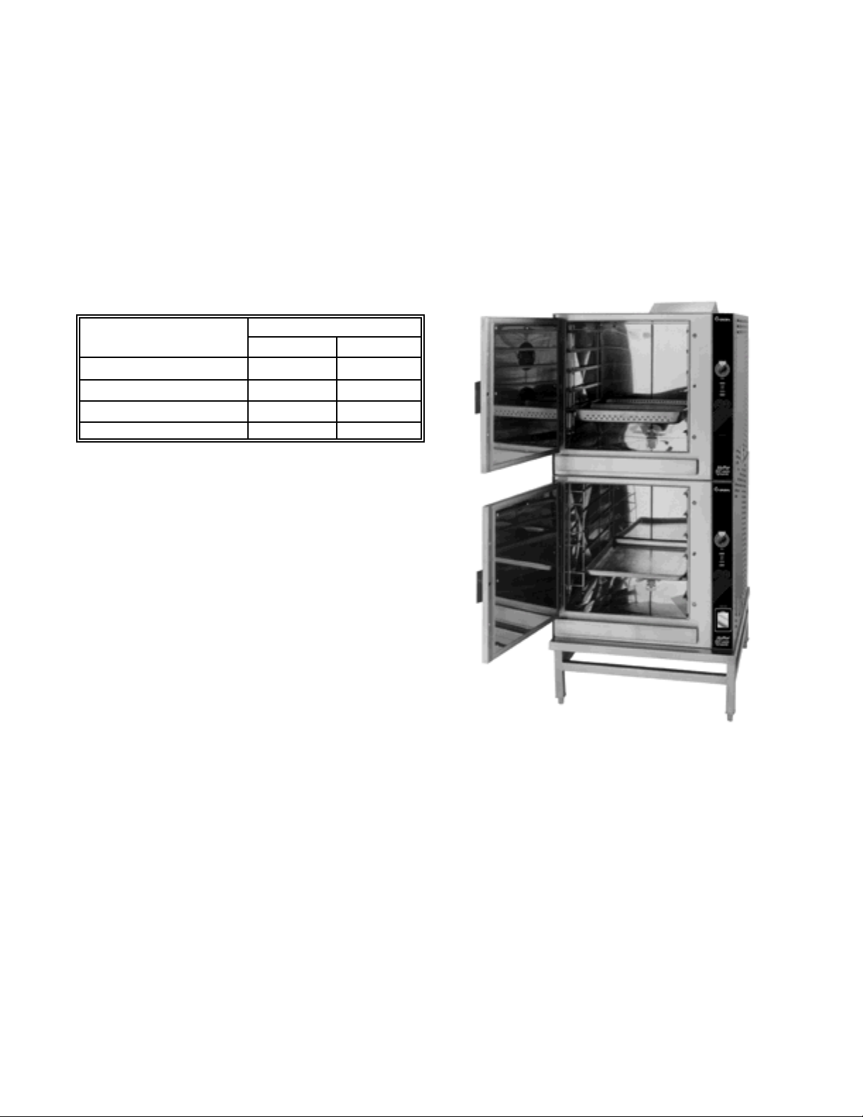
HY-24GF - New Model
Equipment Description
Your Groen HY-12GF HyCapacity HyPerSteam is
designed to give years of service. It consists of a
stainless steel cavity (cooking chamber) which is served
by an electrically-heated atmospheric steam generator.
The HY-24GF has two cavities and two generators.
Two powerful blowers circulate the steam in each cavity
to increase heating efficiency.
A dual position pan rack on the left side of the cavity
can be quickly changed to allow for the use of either 12"
x 20" steamer pans, or 18" x 26" bake pans. The
following table lists pan capacities:
Pan Size/Type
Number of Pans
HY-12GF HY-24GF
12 x 20 x 2½” (steamer) 12 24
12 x 20 x 4" (steamer) 8 16
13 x 18" (half-size bake) 24 48
18 x 26" (bake) 12 24
A stainless steel cabinet encases the cavity, steam
generator and a control compartment which houses
electrical components. Access to the control
compartment is gained by removing the right side
louvered panel. Door hinges are reversible so that the
door may be opened to the left or right. Operating
controls are on the front panel.
Newer model HY-12GF and HY-24GF steamers
(manufactured since November 1999) are equipped
with fully electronic controls and a button-activated preprogrammed CLEAN cycle.
These units are readily identified by their unique
control panels. Touch pad controls, and the distinctive
symbol for steam is integrated into the panel design.
The new models also have fewer panel louvers on the
right side and rear.
The drain system for each cavity includes a spray
condenser, which helps keep steam from coming out
of the unit drain or entering the building drain.
Water Conditioning
It is essential to supply the steam generator with
water that will not form scale. Although the steam
generators are engineered to minimize scale, the
hardness of your water and number of hours the
equipment operates influence scale build-up.
In some areas of the country, water is low enough in
minerals to avoid scale formation. But most water
supplies are full of minerals which form scale. It is
this scale which could lead to an early component
failure. Your water utility or treatment specialists can
test and tell you about the minerals in your water.
Water to the steam generator should have between
10 and 30 parts per million (ppm) total dissolved
solids (TDS) and should have a pH (acidity rating) of
7.0 or higher.
4
OM-HY-12G/24G
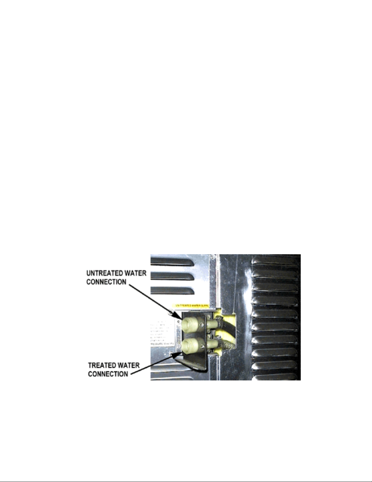
The optional separate water intake could significantly reduce treated water
requirements.
Please follow these simple precautions:
1. The best way to prevent scale is to use a
Groen PureSteem™ Water Treatment
System which has been specifically
designed for Groen steamers and
combination ovens. Do not rely on
unproven water treatment systems sold
for scale prevention and removal. They are
not specifically designed to work with
Groen steamers and combination ovens.
2. A well-maintained water treatment system
and a regular cartridge replacement
schedule is essential.
3. Using a Groen PureSteem™ Water
Treatment System will provide longer steam
generator/boiler life, higher steam capacity,
and reduce maintenance requirements.
4. If you notice a slowdown in steam production
or an increase in deliming, have the steamer
checked for scale build-up. This could be an
indication that the water treatment cartridges
need replacing. Heavy scale reduces the
unit’s ability to boil water, and can even
cause component failure.
OM-HY-12G/24G
5
OM-HY-12G/24G
OM-HY-12G/24G
Installation and Start-Up
WARNING
THE UNIT MUST BE INSTALLED BY PERSONNEL WHO ARE QUALIFIED TO WORK WITH ELECTRICITY
AND PLUMBING. IMPROPER INSTALLATION CAN CAUSE INJURY TO PERSONNEL AND/OR DAMAGE TO
THE EQUIPMENT. THE UNIT MUST BE INSTALLED IN ACCORDANCE WITH APPLICABLE CODES.
CAUTION
DO NOT INSTALL WITH THE RIGHT SIDE VENTS BLOCKED OR WITHIN 12 INCHES OF A HEAT SOURCE
(BRAISING PAN, DEEP FRYER, CHAR BROILER, OR KETTLE).
TO AVOID DRAINAGE PROBLEMS, LEVEL THE UNIT FRONT TO BACK.
HY-12GF
UTILITY CONNECTIONS:
1. Electrical connection ½” (13 mm) conduit fitting.
2. Cold water supply connection ¾” (19 mm) hose
3. Drain connection 2½” (64 mm) hose connection
4. Gas connection ¾” (19 mm) NPT
HY-24GF
UTILITY CONNECTIONS:
1. Electrical connections (each cavity) ½” (13 mm)
conduit fitting.
2. Cold water supply connection (each cavity) ¾” (19
mm) hose
3. Drain connection 2½” (64 mm) hose connection
4. Gas connection (each cavity) ¾” (19 mm) NPT
BURNER FIRING RATES PER CAVITY ELECTRICAL SPECIFICATIONS
Natural Gas @ 3.1" WC L.P. Gas at 10" WC Voltage: 108-126V 1 Phase 50/60 Hz
BTU/hr HY-12G 160,000 150,000 Current per cavity 2.5 AMPS ± 10%
6
OM-HY-12G/24G
A. Installation
When the steamer is received, immediately inspect
the unit thoroughly for external and internal damage.
Report any damage to the carrier.
After the inspection, keep the unit in its shipping
container until it is installed.
The HY-12GF steamer is suitable for installation in
combustible and noncombustible locations. The
flooring in all installations must be noncombustible
material. Minimum installation clearances are:
Right Side Two inches (50 mm)
Left Side Zero inches
Rear of flue Six inches (300 mm)
CAUTION
THE HY-12G STEAMER REQUIRES 24 INCHES
(610 MM) CLEARANCE ON THE RIGHT SIDE
FOR PROPER SERVICE.
The unit must be installed in an adequately ventilated
room with provision for adequate air supply. It must
be installed under a ventilation hood, since flue
products exit the appliance. Items which might
obstruct or restrict air flow for combustion and
ventilation must be removed. Do not obstruct the flue
cover or any vents after installation. Areas around
the unit must be cleared of combustible material.
The installation must conform with local codes or, in
the absence of local codes, with the National Fuel
Gas Code, ANSI Z223.1-latest edition, including:
“The appliance and its individual shutoff valve
must be disconnected from the gas supply
piping system during any pressure testing of that
system at pressures in excess of ½ PSI (3.45
kPa). The appliance must be isolated from the
gas supply piping system by closing its individual
manual shutoff valve during any pressure testing
of the gas supply piping system at pressures
equal to or less than ½ PSI (3.45 kPa).
CAUTION
MAKING ANY ELECTRICAL OR MECHANICAL
CHANGE IN THE UNIT WITHOUT PRIOR
APPROVAL FROM THE GROEN FOOD SERVICE
ENGINEERING DEPARTMENT MAY VOID ALL
WARRANTIES.
1. Electrical Supply Connection
Provide 115 VAC, 60 HZ, 1 PH, 15 AMP service.
Bring conduit in through open frame on under
side of cabinet. Local codes and/or the National
Electrical Code should be observed in
accordance with ANSI/NFPA 70-1987 (or latest
edition). AN ELECTRICAL GROUND IS
REQUIRED. The electrical schematic is located
in the service compartment and in this manual.
Maximum load is 2 1/2 amps. In Canada
,
provide electrical service in accordance with the
Canadian Electrical Code, CSA C22.1 Part 1
and/or local codes.
WARNING
TO AVOID DAMAGE OR INJURY, FOLLOW THE
ELECTRICAL SCHEMATIC EXACTLY WHEN
CONNECTING THE UNIT.
2. Gas Supply Connection
Connection to the gas supply can be completed
with ¾” NPT pipe or approved equivalent.
Although the immediate connection to the
appliance is ¾” NPT, gas supply piping must be
large enough to provide 160,000 BTU/hr. Supply
pressure must be at least 5” W.C. (maximum
14” W.C.) for natural gas or 11” W.C. (maximum
14” W.C.) for LP gas. In Canada, the installation
must conform to the Canadian Gas Code, CAN
1-B149, Installation Codes for Gas Burning
Appliances and Equipment and/or local codes.
After the unit has been connected to the gas
supply, all gas joints must be checked for leaks
.
No flame should be used when checking for
leaks. A thick soap solution or other suitable leak
detector should be used. The unit must have a
separate ground wire for safe operation. This
wire must be at least 8 AWG for 208/240V, or 10
AWG for 480V.
3. Water Connection(s)
Install a check valve to prevent back flow in the
incoming cold water line, as required by local
plumbing codes. Water pressure in the line
should be between 30 and 60 PSI (210 and 420
kPa). If pressure is above 60 PSI, a pressure
OM-HY-12G/24G
7
OM-HY-12G/24G
OM-HY-12G/24G
Installation of drain line without drain box .
regulator will be needed. A ¾ inch R connector
(garden hose type) is used to attach the water
supply to the water inlet valve. The minimum
water feed line diameter is ½ inch (13mm). Use
a washer in the hose connection. Do not allow
the connection to leak, no matter how slowly.
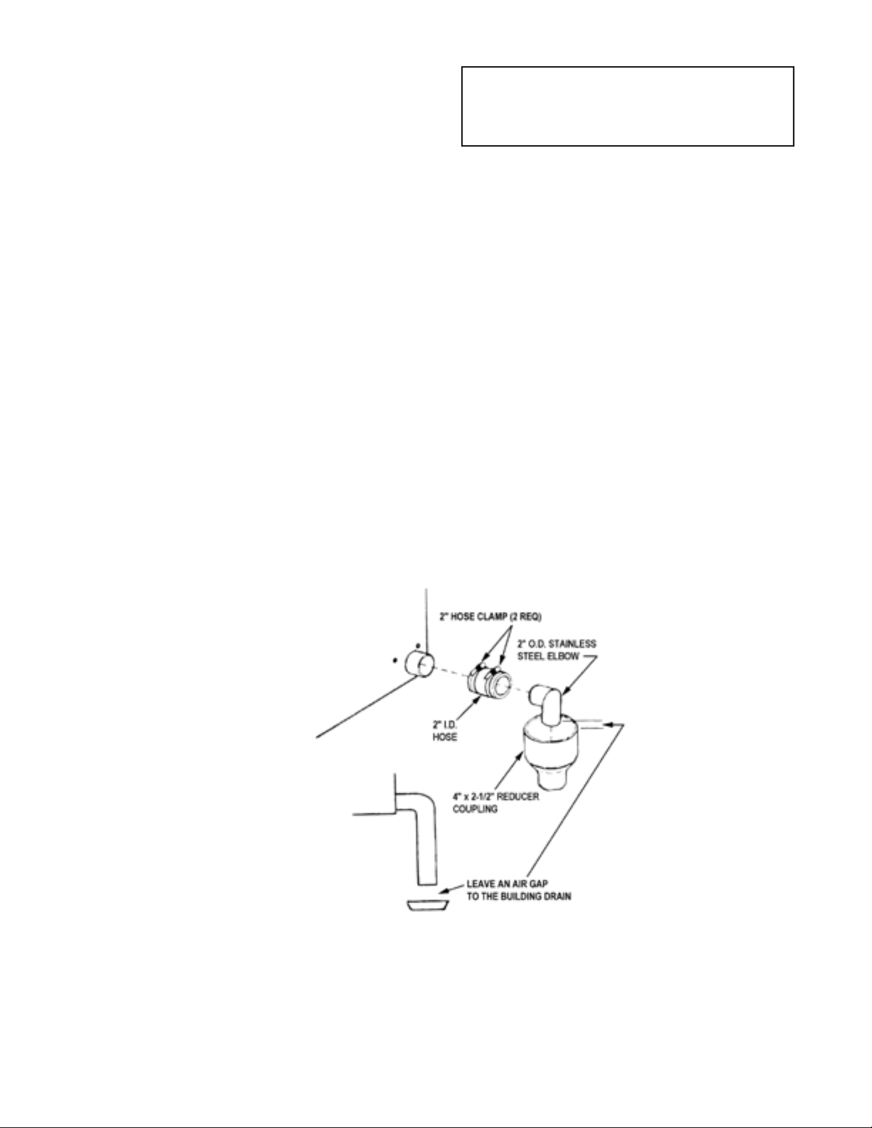
3. Drain Connection
Your HY-12GF/24GF Steamer must be leveled
front to back or pitched slightly to the rear by
adjustment of the bullet feet on the cabinet base.
All units are shipped from the factory with a drain
box and vent pipe. The drain box and vent pipe
provide the necessary air gap when properly
installed. The illustrations below show proper
installation of drain lines from the drain box, and
for tabletop installation, without a drain box.
CAUTION
DO NOT CONNECT THE HOSE DIRECTLY TO
A BUILDING DRAIN. BLOCKING THE DRAIN
COULD BE DANGEROUS.
Do not create any water traps in the drain line. A
trap would cause pressure to build up inside the
cavity during steaming and make the door gasket
leak.
NOTE: Improper drain connection will void the
warranty.
INSTALLATION OPTION ONE: From stainless
steel elbow (P/N 092273) to nearby floor drain, use
Radiator Hose (rated for at least 212ºF) and one
additional hose clamp (P/N 013616).
INSTALLATION OPTION TWO: Using the hose
(P/N 080688) and two hose clamps (P/N 013616),
connect two inch copper tube to floor drain. NOTE:
Drain lines must be pitched downward at
approximately ½ inch per foot. No water traps
should be allowed in the drain line.
IMPORTANT: Leave two inches free air gap to
building drain.
8
 Loading...