

Groen HY-12E Installation Manual
IMPORTANT INFORMATION
IMPORTANT INFORMATION IMPORTANT INFORMATION
IMPORTANT INFORMATION KEEP FOR OPERATOR
KEEP FOR OPERATOR KEEP FOR OPERATOR
KEEP FOR OPERATOR IMPORTANT INFORMATION
IMPORTANT INFORMATION IMPORTANT INFORMATION
IMPORTANT INFORMATION
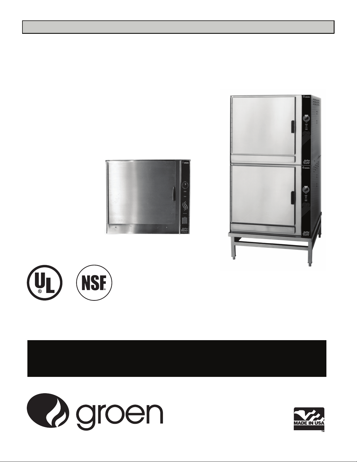
Model HY-24EF (New Model)
OPERATOR MANUAL OM-HY-12E/24E
Part Number 148667 DOMESTIC
Model: HY-12E and HY-24E
HyCapacity HyPerSteam™
Atmospheric Convection
Steamer
Self-Contained
Electric Heated
Model HY-12E
THIS MANUAL MUST BE RETAINED FOR FUTURE REFERENCE. READ,
UNDERSTAND AND FOLLOW THE INSTRUCTIONS AND WARNINGS
CONTAINED IN THIS MANUAL.
FOR YOUR SAFETY
DO NOT STORE OR USE GASOLINE OR OTHER FLAMMABLE VAPORS
AND LIQUIDS IN THE VICINITY OF THIS OR ANY OTHER APPLIANCE
.
OPERATOR MANUAL
Part Number 148667 Rev. D

OM-HY-12E/24E
IMPORTANT - READ FIRST - IMPORTANT
WARNING: THE UNIT MUST BE INSTALLED BY PERSONNEL QUALIFIED TO WORK WITH ELECTRICITY AND
PLUMBING. IMPROPER INSTALLATION CAN CAUSE INJURY TO PERSONNEL AND/OR DAMAGE
TO THE EQUIPMENT. THE UNIT MUST BE INSTALLED IN ACCORDANCE WITH APPLICABLE
CODES.
CAUTION: DO NOT INSTALL THE UNIT IN ANY WAY WHICH WILL BLOCK THE RIGHT SIDE VENTS, OR
WITHIN 12 INCHES OF A HEAT SOURCE SUCH AS A BRAISING PAN, DEEP FRYER, CHAR
BROILER OR KETTLE.
NOTICE: Level the unit front to back, or pitch it slightly to the rear, to avoid drainage problems.
CAUTION: DO NOT LOCATE THE CABINET DIRECTLY OVER A FLOOR DRAIN OR FLOOR SINK. HUMIDITY
OR WATER FROM A DRAIN WILL DAMAGE ELECTRICAL PARTS OF A UNIT.
WARNING: TO AVOID DAMAGE OR INJURY, FOLLOW THE WIRING DIAGRAM EXACTLY WHEN CONNECTING
A UNIT.
WARNING: DO NOT CONNECT THE DRAIN DIRECTLY TO A BUILDING DRAIN.
CAUTION: DO NOT USE PLASTIC PIPE. DRAIN MUST BE RATED FOR BOILING WATER.
WARNING: BLOCKING THE STEAM GENERATOR OR CAVITY DRAIN SCREEN MAY BE HAZARDOUS.
IMPORTANT: Improper drain connection will void warranty.
WARNING: WHEN YOU OPEN THE DOOR, STAY AWAY FROM STEAM COMING OUT OF THE UNIT. STEAM
CAN CAUSE BURNS.
WARNING: BEFORE CLEANING THE OUTSIDE OF THE STEAMER, DISCONNECT THE ELECTRIC POWER
SUPPLY. KEEP WATER AND CLEANING SOLUTIONS OUT OF CONTROLS AND ELECTRICAL
COMPONENTS. NEVER HOSE OR STEAM CLEAN ANY PART OF THE UNIT.
WARNING: ALLOW COOKING CHAMBERS TO COOL BEFORE CLEANING.
WARNING: CAREFULLY READ THE WARNINGS AND FOLLOW THE DIRECTIONS ON THE LABEL OF EACH
CLEANING AGENT. USE SAFETY GLASSES AND RUBBER GLOVES AS RECOMMENDED BY
DELIMING AGENT MANUFACTURER.
WARNING: DO NOT MIX DE-LIMING AGENTS (ACID) AND DE-GREASERS (ALKALI) IN THE STEAM
GENERATOR OR ON THE COOKING CHAMBER WALLS.
WARNING: DO NOT PUT HANDS OR TOOLS INTO THE COOKING CHAMBER UNTIL THE FAN HAS STOPPED
TURNING.
WARNING: DO NOT OPERATE THE UNIT UNLESS THE REMOVABLE RIGHT SIDE PANELS HAVE BEEN
RETURNED TO THEIR PROPER LOCATIONS.
NOTICE: Do not use a cleaning or de-liming agent that contains any sulfamic acid or any chloride, including
hydrochloric acid. If the chloride content of any product is unclear, consult the manufacturer.
WARNING: USE OF ANY REPLACEMENT PARTS OTHER THAN THOSE SUPPLIED BY GROEN OR THEIR
AUTHORIZED DISTRIBUTOR VOIDS ALL WARRANTIES AND CAN CAUSE BODILY INJURY TO THE
OPERATOR AND DAMAGE THE EQUIPMENT. SERVICE PERFORMED BY OTHER THAN FACTORYAUTHORIZED PERSONNEL WILL VOID ALL WARRANTIES.
WARNING: HIGH VOLTAGE EXISTS INSIDE CONTROL COMPARTMENTS. DISCONNECT FROM BRANCH
BEFORE SERVICING. FAILURE TO DO SO CAN RESULT IN SERIOUS INJURY OR DEATH.
OM-HY-12E/24E
2

OM-HY-12E/24E
Table of Contents
IMPORTANT OPERATOR SAFETY WARNINGS ....................................2
EQUIPMENT DESCRIPTION ....................................................4
WATER CONDITIONING/REQUIREMENTS ........................................4
INSTALLATION AND START-UP INSTRUCTIONS ...................................6
OPERATION ...............................................................10
CLEANING .................................................................12
MAINTENANCE .............................................................14
TROUBLESHOOTING ........................................................15
PARTS LIST
................................................................
WIRING DIAGRAM ..........................................................
SERVICE LOG ..............................................................
16
18
19
REFERENCES ..............................................................
WARRANTY PROTECTION ...................................................
20
21
OM-HY-12E/24E
3
3
OM-HY-12E/24E
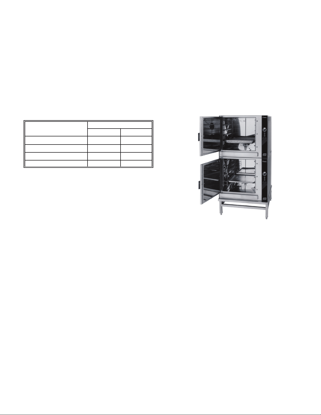
The HY-24EF has two independent
cavities, each with its own steam
generator (New model shown).
Equipment Description
Your Groen HY-12E HyCapacity HyPerSteam is
designed to give years of service. It consists of a
stainless steel cavity (cooking chamber) which is served
by an electrically-heated atmospheric steam generator.
The HY-24EF has two cavities and two generators.
Two powerful blowers circulate the steam in each cavity
to increase heating efficiency.
A dual position pan rack on the left side of the cavity
can be quickly changed to allow for the use of either 12"
x 20" steamer pans, or 18" x 26" bake pans. The
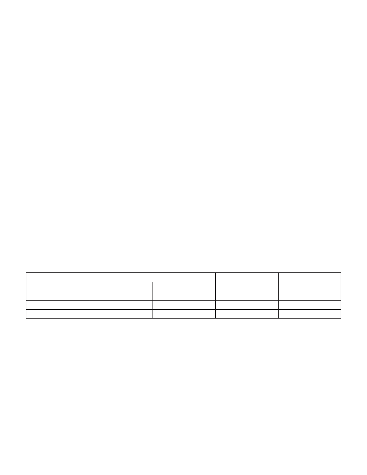
following table lists pan capacities:
Pan Size/Type
Number of Pans
HY-12E HY-24EF
12 x 20 x 2 ” (steamer) 12 24
12 x 20 x 4" (steamer) 8 16
13 x 18" (half-size bake) 24 48
18 x 26" (bake) 12 24
A stainless steel cabinet encases the cavity, steam
generator and a control compartment which houses
electrical components. Access to the control
compartment is gained by removing the right side
louvered panel. Door hinges are reversible so that the
door may be opened to the left or right. Operating
controls are on the front panel.
Newer model HY-12E and HY-24EF steamers
(manufactured since November 1999) are equipped
with fully electronic controls and a button-activated preprogrammed CLEAN cycle.
These units are readily identified by their unique control
panels. Touch pad controls, and the distinctive symbol
for steam is integrated into the panel design. The new
models also have fewer panel louvers on the right side
and rear.
The drain system includes a spray condenser, which
helps keep steam from coming out of the unit drain or
entering the building’s drain.
Water Conditioning
It is essential to supply the steam generator with water
that will not form scale. Even though the steam
generator is engineered to minimize scale formation,
scale development depends on the hardness of your
water and the number of hours the equipment
operates.
In some areas of the country, water is low enough in
minerals to avoid scale formation. But most water
supplies are full of minerals which form scale. It is this
scale which could lead to an early component failure.
Your water utility or treatment specialists can test and
tell you about the minerals in your water. The water
going to the steam generator should have between 10
and 30 parts per million (ppm) total dissolved solids
(TDS) and should have a pH (acidity rating) of 7.0 or
higher.
Please follow these simple precautions:
1. The best way to prevent scale is to use a Groen
PureSteem™ Water Treatment System which has
been specifically designed for Groen steamers and
combination ovens. Do not rely on unproven
water treatment systems sold for scale
prevention and removal. They are not
specifically designed to work with Groen
steamers and combination ovens.
OM-HY-12E/24E
4
OM-HY-12E/24E
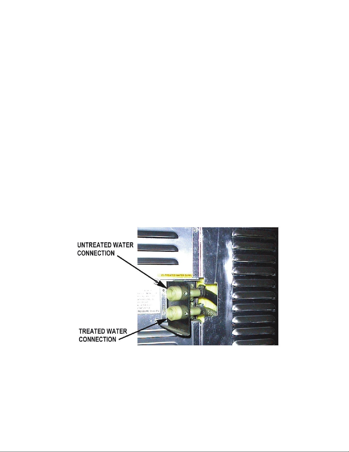
The optional separate water intake can significantly reduce treated water
volume requirements.
2. A well-maintained water treatment system and a
regular cartridge replacement schedule is
essential.
3. Using a Groen PureSteem™ Water Treatment
System will provide longer steam generator/boiler
life, higher steam capacity, and reduce
maintenance requirements.
4. If you notice a slowdown in steam production or an
increase in deliming, have the steamer checked for
scale build-up. This could be an indication that the
water treatment cartridges need replacing. Heavy
scale reduces the unit’s ability to boil water, and
can even cause component failure.
.
OM-HY-12E/24E
5
5
OM-HY-12E/24E
Installation and Start-Up
WARNING
THE UNIT MUST BE INSTALLED BY PERSONNEL WHO ARE QUALIFIED TO WORK WITH
ELECTRICITY AND PLUMBING. IMPROPER INSTALLATION CAN CAUSE INJURY TO
PERSONNEL AND/OR DAMAGE TO THE EQUIPMENT. THE UNIT MUST BE INSTALLED IN
ACCORDANCE WITH APPLICABLE CODES.
WARNING
TO AVOID DAMAGE OR INJURY, FOLLOW THE ELECTRICAL SCHEMATIC EXACTLY
WHEN CONNECTING THE UNIT.
CAUTION
DO NOT INSTALL WITH THE RIGHT SIDE VENTS BLOCKED OR WITHIN 12 INCHES OF A
HEAT SOURCE (BRAISING PAN, DEEP FRYER, CHAR BROILER, OR KETTLE). TO AVOID
DRAINAGE PROBLEMS, LEVEL THE UNIT FRONT TO BACK.
A. Installation
OM-HY-12E/24E
6
OM-HY-12E/24E
1. Electrical Supply Connection
a. Panel Removal
Open the wiring and control panel by removing the
three screws on the right side panel and sliding the
panel forward. Set the panel aside.
b. Supply Voltage
The unit must be operated at the rated nameplate
voltage, plus or minus 10 percent.
c. Terminal Block
The terminal block for incoming power is located at
the back of the control compartment.
The ground terminal is located in the wiring
compartment above the terminal block.
The unit must have a separate ground wire for
safe operation. This wire must be at least
8 AWG for 208/240V, or 10 AWG for 480V.
d. Supply Wire
To determine the wire you need for the power
supply, find the operating voltage and phase on the
unit data plate. Refer to the table below or to the
label on the unit’s back for correct wire size and
insulation temperature rating. The “Electrical
Supply Connection” label inside the unit gives
directions for proper connection of the terminal
block jumpers.
The specified wire must be used in order to meet
Underwriters Laboratories and National Electric
Code requirements.
The knockout hole is sized for a two inch conduit
fitting.
e. Branch Circuit Protection
Groen strongly recommends that the HY-12E
Steamer or each cavity of the HY-24EF have its
own branch circuit protection. Each currentcarrying conductor must have overcurrent
protection. Refer to the label for proper wire size
and type. Watertight connections to the unit are
required.
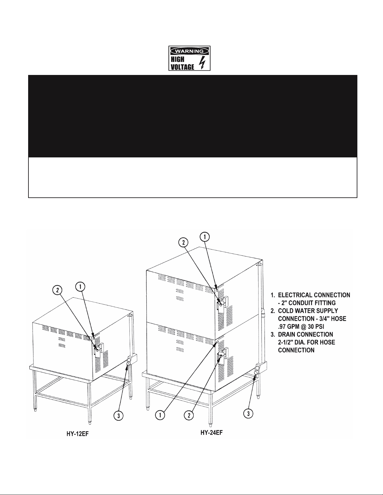
2. Water Connection(s):
Install a check valve to prevent back flow in the
incoming cold water line, as required by local plumbing
codes. Water pressure in the line should be between
30 and 60 PSIG (210 and 420 kPa). If pressure is
above 60 PSIG, a pressure regulator will be needed. A
inc h R connector (garden hose type) is used to
attach the water supply to the water inlet valve. The
minimum water feed line diameter is inc h (13mm).
Use a washer in the hose connection. Do not allow the
connection to leak, no matter how slow it may be.
If you have the twin water connection option, put
the treated water (softened) to the bottom intake
(facing the rear of the unit), and untreated water to
the top. Connections for both are made as
described above.
Voltage
Wiring - Insulation Rating
Amperes Maximum KW
THWN (70ºC) THWN (90ºC)
208 Volt, 3 Phase
Not Approved 1/0 AWG 92 32.5
240 Volt, 3 Phase
Not Approved 1 AWG 80 32.5
480 Volt, 3 Phase
1 AWG 6 AWG 40 32.5
OM-HY-12E/24E
7
7
OM-HY-12E/24E
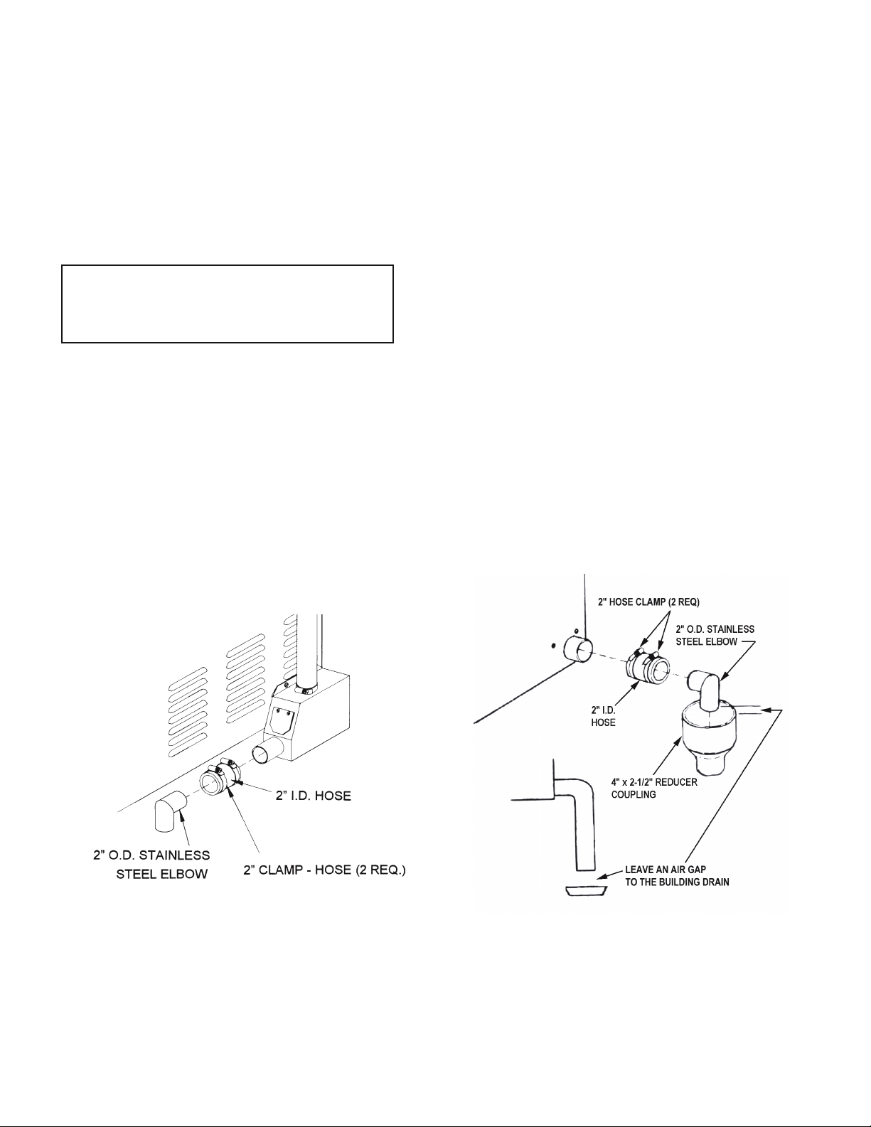
Installation of drain line without drain box
(tabletop models only).
Drain Connection with Drain Box (All units are
shipped from the factory with a drain box). Old
model shown.
3. Drain Connection
The HY-12E/24E Steamer must be leveled front to
back or pitched slightly to the rear by adjustment of
the bullet feet on the cabinet base.
All units are shipped from the factory with a drain
box and vent pipe. The drain box and vent pipe
provide the necessary air gap when properly
installed. The illustrations below show proper
installation of drain lines from the drain box, and for
tabletop installation, without a drain box.
CAUTION
DO NOT CONNECT THE HOSE DIRECTLY TO
A BUILDING DRAIN. BLOCKING THE DRAIN
COULD BE DANGEROUS.
Do not create any water traps in the drain line. A
trap would cause pressure to build up inside the
cavity during steaming and make the door gasket
leak.
NOTE: Improper drain connection will void the
warranty.
INSTALLATION OPTION ONE: From stainless steel
elbow (P/N 092273) to nearby floor drain, use Radiator
Hose (rated at least 212ºF) and one additional hose
clamp (P/N 013616).
INSTALLATION OPTION TWO: Using the hose (P/N
080688) and two hose clamps (P/N 013616), connect
two inch copper tube to floor drain. NOTE: Drain lines
must be pitched downward at approximately inc h per
foot. No water traps should be allowed in the drain line.
IMPORTANT: Leave two inches free air gap to
building drain.
OM-HY-12E/24E
8
 Loading...