

Page 1
IMPORTANT INFORMATION j KEEP FOR OPERATOR j IMPORTANT INFORMATION
OPERATOR MANUAL OM-HH
Part Number 121034 DOMESTIC
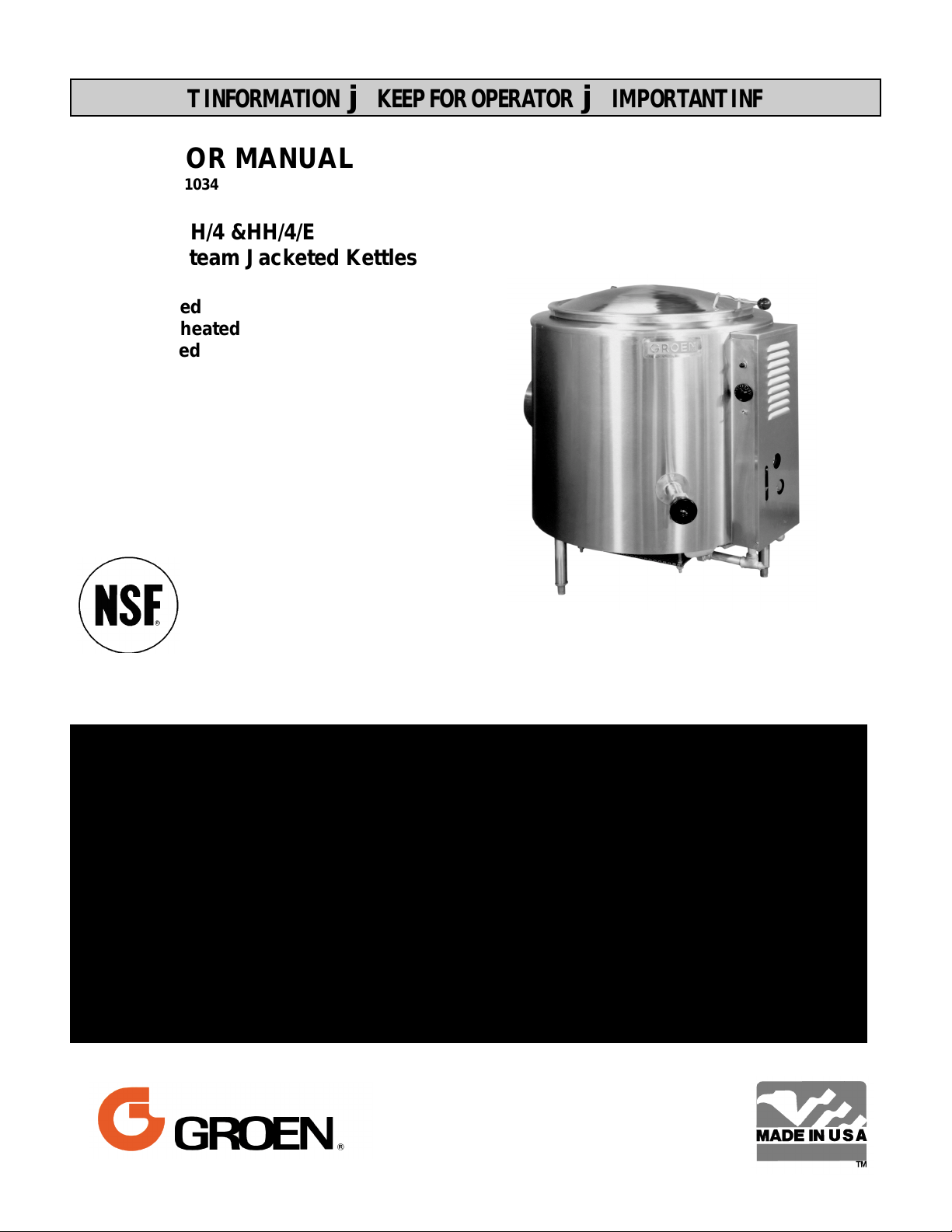
MODEL: HH/4 &HH/4/E
Steam Jacketed Kettles
Self-Contained
Natural Gas heated
Floor mounted
Stationary
THIS MANUAL MUST BE RETAINED FOR FUTURE REFERENCE. READ, UNDERSTAND AND
FOLLOW THE INSTRUCTIONS AND WARNINGS CONTAINED IN THIS MANUAL.
WARNING
DO NOT STORE OR USE GASOLINE OR OTHER FLAMMABLE VAPORS AND LIQUIDS
IN THE VICINITY OF THIS OR ANY OTHER APPLIANCE.
POST IN A PROMINENT LOCATION
INSTRUCTIONS TO BE FOLLOWED IN THE EVEN USER SMELLS GAS. THIS INFORMATION SHALL BE OBTAINED BY CONSULTING YOUR LOCAL GAS SUPPLIER. AS A MINIMUM, TURN OFF THE GAS AND CALL YOUR GAS COMPANY AND YOUR AUTHORIZED
SERVICE AGENT. EVACUATE ALL PERSONNEL FROM THE AREA.
WARNING
IMPROPER INSTALLATION, ADJUSTMENT, ALTERATION, SERVICE OR MAINTENANCE
CAN CAUSE PROPERTY DAMAGE, INJURY OR DEATH. READ THE INSTALLATION, OPERATING AND MAINTENANCE INSTRUCTIONS THOROUGHLY BEFORE INSTALLING
OR SERVICING THIS EQUIPMENT.
Page 2
OM-HH
IMPORTANT — READ FIRST — IMPORTANT
WARNING INSTALLATION OF THE UNIT MUST BE DONE BY PERSONNEL QUALIFIED TO WORK
WITH ELECTRICITY AND PLUMBING. IMPROPER INSTALLATION CAN CAUSE INJURY
TO PERSONNEL AND/OR DAMAGE TO EQUIPMENT. UNIT MUST BE INSTALLED IN
ACCORDANCE WITH ALL APPLICABLE CODES.
CAUTION TO AVOID DAMAGING PARTS OF THE BURNER SYSTEM UNDERNEATH THE KETTLE,
LIFT THE UNIT ONLY BY THE RING BENEATH THE OUTER PORTION OF THE BODY.
WARNING DO NOT ATTACH THE UNIT TO A TYPE “B” VENT. FAILURE COULD RESULT IN FIRE
OR PROPERTY DAMAGE.
WARNING DO NOT CONNECT ANY PIPING TO THE SAFETY VALVE. THE VALVE MUST BE FREE
TO VENT STEAM AS NEEDED. ELBOW, ATTACHED TO THE SAFETY VALVE, SHOULD
POINT DOWN TOWARD THE FLOOR. IMPROPER INSTALLATION WILL VOID THE
WARRANTY!
DANGER ELECTRICALLY GROUND THE UNIT AT THE TERMINAL PROVIDED. FAILURE TO
GROUND THE UNIT COULD RESULT IN ELECTROCUTION AND DEATH.
CAUTION BE SURE ALL OPERATORS READ, UNDERSTAND AND FOLLOW THE OPERATING
INSTRUCTIONS, CAUTIONS AND SAFETY INSTRUCTIONS CONTAINED IN THIS
MANUAL.
CAUTION DO NOT OVERFILL THE KETTLE WHEN COOKING, HOLDING OR CLEANING. KEEP
LIQUIDS A MINIMUM OF 2-3” (5-8 CM) BELOW THE KETTLE BODY RIM TO ALLOW
CLEARANCE FOR STIRRING, BOILING PRODUCT AND SAFE TRANSFER.
CAUTION KEEP FLOORS IN FRONT OF KETTLE WORK AREA CLEAN AND DRY. IF SPILLS
OCCUR, CLEAN IMMEDIATELY TO AVOID DANGER OF SLIPS OR FALLS.
WARNING KEEP WATER AND SOLUTIONS OUT OF CONTROLS AND BURNERS. NEVER SPRAY
OR HOSE CONTROL CONSOLE, ELECTRICAL CONNECTIONS, ETC.
CAUTION MOST CLEANERS ARE HARMFUL TO THE SKIN, EYES, MUCOUS MEMBRANES AND
CLOTHING. PRECAUTIONS SHOULD BE TAKEN TO WEAR RUBBER GLOVES,
GOGGLES OR FACE SHIELD AND PROTECTIVE CLOTHING. CAREFULLY READ THE
WARNINGS AND FOLLOW THE DIRECTIONS ON THE LABEL OF THE CLEANER TO BE
USED.
Important Do not mix the parts of different tangent draw-off valve assemblies during washing. The
parts are not interchangeable.
NOTICE NEVER leave a sanitizer in contact with stainless steel surfaces LONGER THAN 10
minutes. Longer contact can cause corrosion.
WARNING FAILURE TO PERIODICALLY CHECK SAFETY VALVE OPERATION COULD RESULT IN
PERSONAL INJURY AND/OR DAMAGE TO EQUIPMENT.
WARNING WHEN TESTING, AVOID ANY EXPOSURE TO THE STEAM BLOWING OUT OF THE
SAFETY VALVE. DIRECT CONTACT COULD RESULT IN SEVERE BURNS.
WARNING TO AVOID INJURY, READ AND FOLLOW ALL PRECAUTIONS STATED ON THE LABEL
OF THE WATER TREATMENT COMPOUND.
WARNING BEFORE REPLACING ANY PARTS, DISCONNECT THE UNIT FROM THE ELECTRIC
POWER SUPPLY AND CLOSE THE MAIN GAS COCK. ALLOW FIVE MINUTES FOR
UNBURNED GAS TO VENT.
CAUTION USE OF ANY REPLACEMENT PARTS OTHER THAN THOSE SUPPLIED BY GROEN OR
THEIR AUTHORIZED DISTRIBUTOR CAN CAUSE INJURY TO THE OPERATOR AND
DAMAGE TO THE EQUIPMENT AND WILL VOID ALL WARRANTIES.
Important Service performed by other than factory authorized personnel will void all warranties.
WARNING KEEP AREA AROUND KETTLE FREE AND CLEAR OF COMBUSTIBLE MATERIALS.
FAILURE TO DO SO COULD RESULT IN FIRE AND PROPERTY DAMAGE.
2
Page 3
OM-HH
Table of Contents
IMPORTANT OPERATOR WARNINGS ....................................2
EQUIPMENT DESCRIPTION .............................................4
INSPECTION & UNPACKING ............................................6
INSTALLATION .......................................................7
INITIAL START-UP ....................................................8
OPERATION .........................................................9
SEQUENCE OF OPERATION ...........................................11
MAINTENANCE .....................................................12
CLEANING ..........................................................14
TROUBLESHOOTING .................................................15
PARTS LISTS ........................................................ 18
SCHEMATICS ....................................................... 20
REFERENCES .......................................................22
MAINTENANCE LOG ..................................................23
WARRANTY .........................................................24
References
KLENZADE SALES CENTER ECOLAB. Inc.
370 Wabasha
St. Paul, Minnesota 55102
800/352-5326 or 612/293-2233
NATIONAL FIRE PROTECTION ASSOCIATION
60 Battery March Park
Quincy, Massachusetts 02269
NFPA/70 - The National Electrical Code
ECONOMICS LABORATORY, INC.
St. Paul, Minnesota 55102
NATIONAL SANITATION FOUNDATION
3475 Plymouth Rd.
Ann Arbor, Michigan 48106
UNDERWRITERS LABORATORIES, INC.
333 Pfingsten Road
Northbrook, Illinois 60062
ZEP MANUFACTURING CO.
1310-T Seaboard Industrial Blvd.
Atlanta, Georgia 30318
3
Page 4
OM-HH
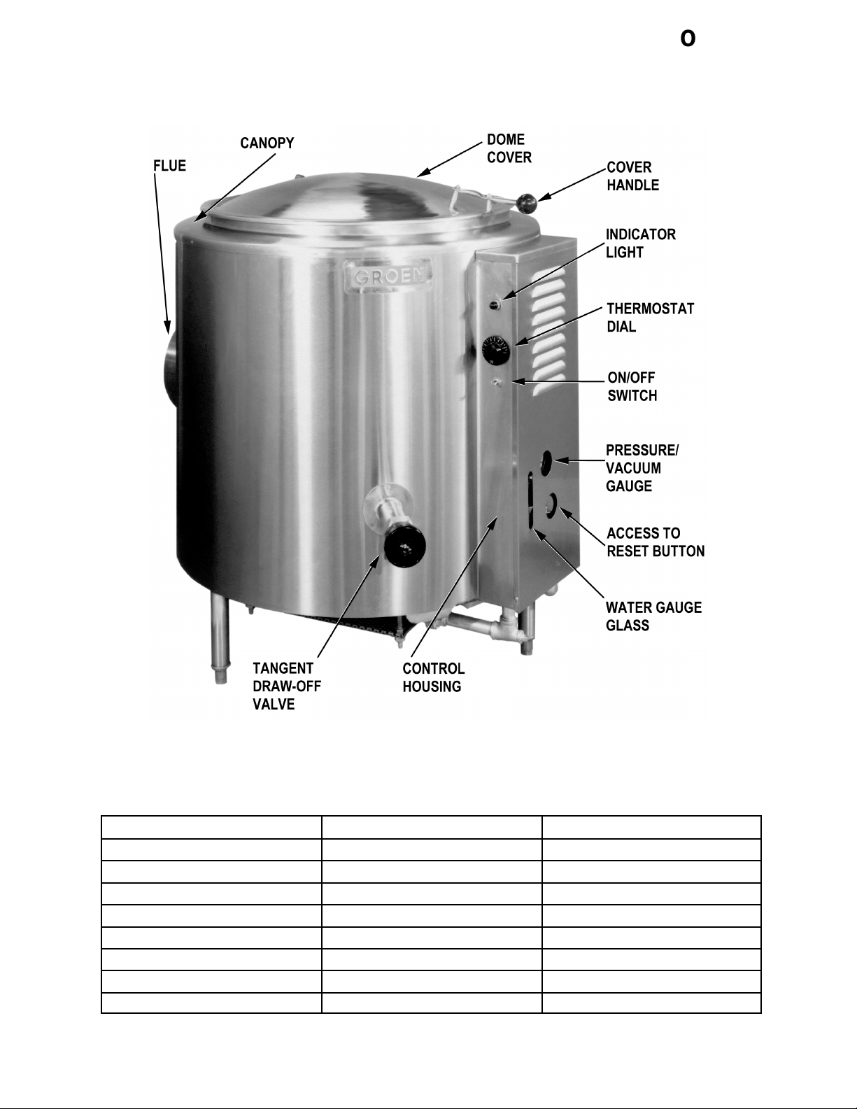
Equipment Description
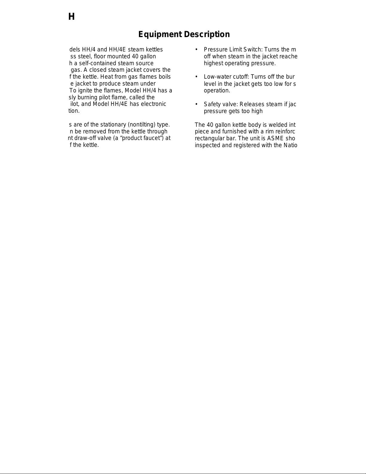
Groen Models HH/4 and HH/4E steam kettles
are stainless steel, floor mounted 40 gallon
kettles with a self-contained steam source
heated by gas. A closed steam jacket covers the
lower b of the kettle. Heat from gas flames boils
water in the jacket to produce steam under
pressure. To ignite the flames, Model HH/4 has a
continuously burning pilot flame, called the
standing pilot, and Model HH/4E has electronic
spark ignition.
The kettles are of the stationary (nontilting) type.
Liquids can be removed from the kettle through
the tangent draw-off valve (a “product faucet”) at
the front of the kettle.
All exposed surfaces are stainless steel. An
insulated canopy protects the kettle body, and a
housing encloses all the controls. A one piece
dome cover is hinged to the kettle.
Three tubular legs support the unit. Bullet feet on
the legs can be adjusted to level the kettle.
Controls used by the operator include the
ON/OFF switch, which controls electric power for
the unit, and the thermostat, which sets the
cooking temperature.
Instruments are provided to show what is
happening inside the unit:
• Pressure Limit Switch: Turns the main burner
off when steam in the jacket reaches its
highest operating pressure.
• Low-water cutoff: Turns off the burner if water
level in the jacket gets too low for safe
operation.
• Safety valve: Releases steam if jacket
pressure gets too high
The 40 gallon kettle body is welded into one
piece and furnished with a rim reinforced by a
rectangular bar. The unit is ASME shop
inspected and registered with the National Board
for working pressures up to 30 PSI.
The standard 2 inch tangent draw-off has a
removable strainer with ¼ inch holes which keep
pieces of product that are too large from going
down into the draw-off.
The jacket is filled at the factory with water
containing rust inhibitors. The kettle can operate
at steam pressures up to 30 PSI, which provide
kettle temperatures of 150 to approximately
270°F (56 to 132ºC). This temperature range
allows the operator to use the kettle for warming,
simmering, boiling, or braising.
Optional equipment for the HH/4 kettles includes:
• Water gauge glass: shows the level of water
within the steam jacket
• Pressure/vacuum gauge: shows the steam
pressure and if there is air in the jacket
• Indicator lamp: Lights when the kettle is being
heated
Automatic controls within the unit:
• Gas Pressure Regulator: Adjusts gas
pressure up to 14" W.C.
• Three inch draw-off valve
• c” perforated or solid disc strainer
• Basket inserts (TRI-BC)
• Water fill faucets
• Automatic water filler
• Kettle brush kit
• 316 stainless steel liner
4
Page 5
OM-HH
KETTLE CHARACTERISTICS
Model HH/4 HH/4/E
Ignition Pilot Spark
Capacity, gallons (liters) 40 (150) 40 (150)
Rim Height, inches (mm) 38 (960) 38 (960)
Depth, inches (mm) 22 (560) 22 (560)
Diameter, inches (mm) 26 (660) 26 (660)
Overall front-to back, inches (mm) 40½ (1030) 40½ (1030)
Firing Rate, BTU/hour 129,000 129,000
Energy into product, BTU/hour 82,500 82,500
5
Page 6
OM-HH
Inspection & Unpacking
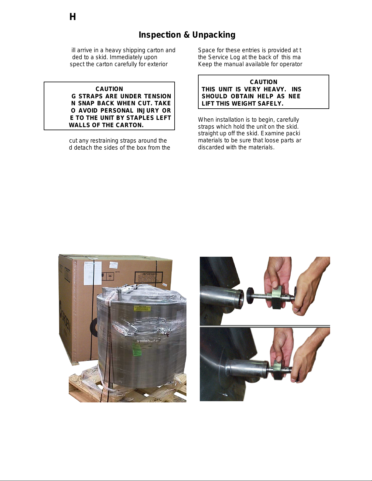
The unit will arrive in a heavy shipping carton and
will be banded to a skid. Immediately upon
receipt, inspect the carton carefully for exterior
damage.
CAUTION
SHIPPING STRAPS ARE UNDER TENSION
AND CAN SNAP BACK WHEN CUT. TAKE
CARE TO AVOID PERSONAL INJURY OR
DAMAGE TO THE UNIT BY STAPLES LEFT
IN THE WALLS OF THE CARTON.
Carefully cut any restraining straps around the
carton and detach the sides of the box from the
skid. Pull the carton up off the unit.
Thoroughly inspect for concealed damage.
Report any shipping damage or incorrect
shipments to the delivery agent. Write down the
model number, serial number, and installation
date, and retain this information for future
reference.
Space for these entries is provided at the top of
the Service Log at the back of this manual.
Keep the manual available for operators to use.
CAUTION
THIS UNIT IS VERY HEAVY. INSTALLER
SHOULD OBTAIN HELP AS NEEDED TO
LIFT THIS WEIGHT SAFELY.
When installation is to begin, carefully cut any
straps which hold the unit on the skid. Lift the unit
straight up off the skid. Examine packing
materials to be sure that loose parts are not
discarded with the materials.
The tangent draw-off valve is usually shipped
unassembled. Once the kettle is unpacked, it is
easily attached, as shown below. The large nut
which attaches the valve to the kettle should only
be hand tightened.
The kettle will be banded to a skid, inside a
heavy carton.
Assemble and attach the tangent draw-off
valve after the kettle is unpacked.
6
Page 7
Installation
A. Installation
The unit should be installed in a ventilated room
for efficient performance. Items which obstruct or
restrict the flow of air for combustion and
ventilation must be removed. The area around the
appliance must be free of combustible materials.
OM-HH
rest hood supports on the diverter. The
ventilating hood should comply with local
codes and/or ANSI/NFPA-96 Latest Edition.
Local codes may also require that the kettle
be electrically interlocked to shut off the gas
supply and prevent operation if the exhaust
fan is not operating or if the fire suppression
system is activated.
WARNING
THE KETTLE MUST BE INSTALLED BY
PERSONNEL QUALIFIED TO WORK WITH
ELECTRICITY. IMPROPER INSTALLATION
CAN RESULT IN INJURY TO PERSONNEL
AND/OR DAMAGE TO EQUIPMENT.
1. Installation requires connection with gas and
electrical services. See items 8 to 14 for
details.
2. To protect the unit from damage, leave it on
the shipping pallet until installation. When
installation is to begin, cut the straps holding
the kettle, and hoist it straight up off the skid.
NOTICE:To avoid damaging parts of the
burner system underneath the kettle, LIFT
THE UNIT ONLY BY THE RING beneath the
outer edge of the body.
3. Install the unit with a minimum clearance to
combustible and non-combustible
construction of six inches at the sides and six
inches between the draft diverter and the
wall. Also leave enough room for cleaning,
maintenance, and service.
5. Level the unit by turning the bullet feet.
6. Confirm that the jacket water level is between
the marks on the gauge glass. If the water is
low, follow the instructions in “Jacket Filling”
in the “Maintenance” Section of this manual.
Do not connect the unit to a water supply.
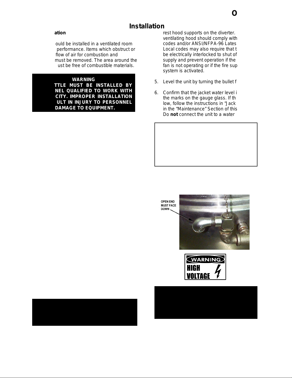
CAUTION
DO NOT CONNECT ANY PIPING TO THE
SAFETY VALVE. IT MUST BE FREE TO
VENT STEAM AS NEEDED. ELBOW
SHOULD POINT DOWN TOWARD FLOOR.
IMPROPER INSTALLATION WILL VOID
WARRANTY!
7. The open end of the elbow at the safety valve
outlet must be directed down. If it is not, turn
the elbow to the correct position.
4. The draft diverter (flue) shipped with the
kettle is the correct height and shape for
maximum performance. Slide the diverter
onto the flue collar at the back of the kettle
and secure it with the two sheet metal screws
provided.. Do not change the diverter in any
way.
Any mechanical, electrical, or gas type change
must be approved by the Groen Food Service
Engineering Department.
WARNING
DO NOT ATTACH THE UNIT TO A TYPE “B”
VENT. FAILURE COULD RESULT IN A FIRE
AND/OR PROPERTY DAMAGE.
Install the unit under a ventilation hood, or
vent the flue directly to a masonry chimney.
Put a hood at least several inches above the
upper end of the draft diverter (flue). Do not
WARNING
ELECTRICALLY GROUND THE UNIT AT
THE TERMINAL PROVIDED. FAILURE TO
GROUND UNIT COULD RESULT IN
ELECTROCUTION AND DEATH.
8. Provide 115 VAC, 60 HZ, 1 PH, 15 AMP
electrical service. Use ½ inch waterproof
conduit and waterproof connections. Observe
local codes and/or The National Electrical
Code in accordance with ANSI/NFPA 70 latest edition. An electrical ground is
7
Page 8
OM-HH
required. The electrical schematic is on the
inside of the service panel and in this manual.
9. Internal gas lines were cleaned and closed off
with a gas valve before the unit was shipped.
Free external gas lines of lint, dirt, metal
chips, sealant, grease, oil, or other contami-
nants before connecting them to the kettle.
10. Connect the kettle gas valve to the gas
service main with ¾ inch IPS line or an
approved equivalent.
11. Installation must conform with local codes
and with the National Fuel Gas Code, ANSI Z
223.1-1988 (or latest edition). Install the unit
in an adequately ventilated room and ensure
an adequate air supply. The best ventilation
will use a vent hood and exhaust fan with no
direct connection between the vent duct and
the flue. Do NOT obstruct the flue or vent
duct after installation.
12. Adequate space for proper service and
operation is required. Do NOT block any air
intake spacings to the combustion chamber
or obstruct the air flow by piling or stacking
anything near the kettle.
13. .After the kettle has been connected to the
gas supply, check each gas line joint for
leaks. DO NOT USE A FLAME TO CHECK
FOR LEAKS. A thick soap solution or other
leak detector should be employed.
14. The appliance and its individual shutoff valve
must be disconnected from the gas supply
piping system during any pressure testing at
test pressures in excess of ½ PSI (3.48
kPa). The unit must be isolated from the gas
supply piping system by closing its manual
shutoff valve during any pressure testing of
the gas piping system at pressures equal to
or less than ½ PSI (3.48 kPa).
15. Check the following points to confirm that
your HH kettle has been installed properly.
f. Safety valve outlet is pointed down.
g. Connected with a waterproof, 115 volt, 15
amp supply of electric power and
grounded in accordance with electrical
codes.
h. Natural gas lines cleaned before
connection.
i. Gas connected with ¾ inch pipe.
j. Gas line joints checked for leaks.
k. No obstruction to air supply or venting
B. Initial Start-Up.
After installation, the installer should test the
kettle to ensure that it is operating correctly.
1. Remove all literature and packing materials
from the inside and outside of the unit. Clean
out any material that might clog or damage
the tangent draw-off valve.
2. Close the draw-off valve, and put water into
the kettle to a depth of about six inches. Test
draw-off operation by opening it all the way,
then closing it before all the water runs out.
3. Make sure the supplies of gas and electric
power are on.
4. Following “To Start Kettle” instructions on
Page nine of this manual, begin heating the
water at the highest thermostat setting. The
heating indicator light should come on as
soon as you turn up the thermostat dial, and
heating should continue until the water boils.
5. To turn off the unit, follow “To Turn Off Kettle”
instructions on page 10.
If the kettle functions as described, it is ready for
use. If it does not, contact your area Groen
Authorized Service Representative.
a. Sufficient room between the kettle and
nearby objects for cleaning and service.
b. Minimum clearance of six inches from the
kettle’s sides and draft diverter.
c. Unit vented to a hood or chimney.
d. Kettle is level.
e. Correct amount of water in the jacket.
8
Page 9

OM-HH
IMPORTANT:
BE SURE ALL OPERATORS READ, UNDERSTAND AND FOLLOW THE OPERATING
INSTRUCTIONS, CAUTIONS AND SAFETY INSTRUCTIONS CONTAINED IN THIS MANUAL.
WARNING
AVOID ALL DIRECT CONTACT WITH HOT SURFACES. DIRECT SKIN CONTACT COULD RESULT
IN SEVERE BURNS.
AVOID ALL DIRECT CONTACT WITH HOT FOOD OR WATER IN THE KETTLE. DIRECT CONTACT
COULD RESULT IN SEVERE BURNS.
Operation
A. Controls
Operator controls for the HH/4 kettle are:
1. Main gas valve, which controls the supply of
gas from the main to the unit.
2. ON/OFF (toggle) switch. This switch controls
electrical power to the control circuits.
3. Thermostat dial, which turns the thermostat
on or off and sets the operating temperature
of the kettle.
4. Reset button, used in lighting the pilot burner
(on standing pilot model only).
Refer to the photograph in the “Equipment
Description” section of this manual for the location
of controls and other features.
B. Operating Procedure
WARNING
KEEP KETTLE AREA FREE AND CLEAR OF
ALL COMBUSTIBLE MATERIALS.
1. To Start Kettle
show 20 or more inches of vacuum
(that is, a reading of 20 to 30 below 0),
see "Jacket Vacuum" on Page 13 of
this manual.
Make sure the kettle shows at least 20
inches of vacuum when cold.
c. Make sure the strainer is covering the
draw-off outlet at the bottom of the
kettle.
a. CHECK THE
WATER LEVEL IN
THE JACKET
EVERY DAY. The
level must be
between the lines
on the gauge glass.
If the level is low,
see "Jacket Filling”
on Page 13.
b. While the kettle is
cold, check the
pressure gauge. If
the gauge does not
d. Set both the toggle (ON/OFF) switch
and the thermostat dial to “OFF”.
e. If the unit has just been turned off,
allow 5 minutes for unburned gas to
clear, before you turn the kettle on
again.
f. Turn the gas valve ON (handle lined up
with gas pipe), if it is not already on.
g. If you are using Model HH/4E with
electronic spark ignition, or if you are
using a Model HH/4 unit with the pilot
burner already lit, all you have to do to
start heating the kettle is:
(1) Press the ON/OFF switch to “ON.”
9
Page 10

OM-HH
(2) Turn the thermostat dial to the
desired setting.
h. If the HH/4 pilot is not lit:
(1) Locate the red reset button on the
automatic gas control valve inside the
control housing. (See photo, Page 5).
(2) Hold a flame to the pilot burner and
press down on the reset button to
start the flow of gas. Continue to
hold the button in for about 60
seconds after the pilot burner is lit.
(3) Release the button. The pilot should
stay lit.
(4) Press the On/Off switch in the “ON”
position.
(5) Turn the thermostat to the desired
setting.
2. To Turn Off the Kettle
a. Turn the thermostat dial to “OFF.”
b. Press the ON/OFF switch “OFF.”
c. Before servicing the unit, or if it will not be
used for a week or more, continue by:
(1) Turning the main gas valve OFF (at
right angles to the gas pipe).
(2) Turning off the unit’s electrical power
at the circuit breaker or fuse box.
3. If Electric Power Fails:
a. Do not try to operate the kettle. The main
burner can not be lit until the power is
restored.
b. When the power returns, follow the
procedure in “To Start Kettle,” above.
4. To Relight Kettle
Follow the steps described in “To Start Kettle”
above.
5. To Transfer Product or Empty Kettle:
a. The kettle is emptied by means of its
draw-off valve, by ladling product out, or
using the optional TRI-BC Cooking
Basket Set.
WARNING
OPEN THE KETTLE LID CAREFULLY TO
AVOID STEAM. DIRECT CONTACT WITH
STEAM COULD CAUSE BURNS.
CAUTION
DO NOT OVERFILL THE KETTLE WHEN
COOKING, HOLDING OR CLEANING. KEEP
LIQUIDS 2-3” (5-8 cm) BELOW THE KETTLE
BODY RIM TO ALLOW CLEARANCE FOR
STIRRING, BOILING PRODUCT AND SAFE
TRANSFER.
CAUTION
KEEP FLOORS IN FRONT OF THE KETTLE
WORK AREA CLEAN AND DRY. IF SPILLS
OCCUR, CLEAN AT ONCE TO AVOID SLIPS
OR FALLS.
b. Use of Optional Basket Insert
The optional kettle basket insert set
helps cook water-boiled products such
as eggs, potatoes, vegetables, shell
fish, pasta or rice. The nylon mesh liner
must be used for products smaller than
the basket mesh, ( ¼” (6 mm). This
includes rice and small pasta shapes.
c. Tips For Optional Basket Use.
(1) Allow for displacement of the three
baskets and product. This may mean
only filling the kettle half way. Test
baskets and product displacement with
cold water and the kettle OFF.
CAUTION
DO NOT OVERFILL THE KETTLE WHEN
COOKING, HOLDING OR CLEANING.
KEEP LIQUIDS AT LEAST 2-3” (5-8 cm)
BELOW THE KETTLE RIM TO ALLOW
CLEARANCE FOR STIRRING, BOILING
AND SAFE PRODUCT TRANSFER.
(2) Load baskets on level, stable work
surface.
10
(3) Lift loaded baskets with both hands.
Get help if the basket is too heavy.
Page 11

WARNING
AVOID DIRECT CONTACT WITH HOT FOOD
OR WATER IN THE KETTLE. DIRECT
CONTACT COULD CAUSE SEVERE BURNS.
(4) Slowly lower product into kettle and
securely hook the basket to the “Y” frame.
(5) When removing baskets with cooked
product, lift straight up, ensuring baskets
Sequence of Operation
OM-HH
clear the kettle rim. Wear protective oven
mitts and protective apron
(6) Allow hot water to fully drain from product,
before moving basket away from the kettle.
If baskets are too heavy, get help. Remove
product immediately from basket into
another container, being sure to avoid
contact with hot product and hot basket.
(7) Place baskets with food on a stable, flat
surface, or inside a solid steamer or bake
pan, to catch any remaining hot water
draining from product.
The following “action-reaction” outline will help the
user understand how the equipment works.
A. Model HH/4 with Standing Pilot Ignition
Pressing the reset button overrides the automatic
control and opens the pilot burner valve, allowing
gas from the supply line into the pilot. Lighting and
sustaining the pilot flame for 60 seconds heats the
thermocouple to operating temperature, so that it
can supply electric current at 20 to 25 millivolts.
Current from the thermocouple powers a coil that
holds the pilot burner valve open. If the pilot flame
goes out and the thermocouple cools, the valve
closes and prevents gas flow into the unit.
Once the pilot burner valve opens, gas is available
at the main burner valve, which is normally closed.
Pushing the toggle switch to “ON” provides 120 Volt
electric power to the thermostat. When the operator
turns the thermostat dial to a setting, the switch
closes and allows power to the heating indicator
light and a coil at the main burner valve. The coil
opens the main burner valve. Gas then flows to the
main burner where it is ignited by the pilot flame.
B. Model HH/4/E with Electronic Spark Ignition
Pressing the toggle switch “ON”, supplies electric
power to the thermostat. Turning the dial to an
operating setting closes the thermostat switch and
energizes the gas control. Simultaneously, an arc is
established at the spark gap, and the pilot burner
automatic valve is opened. When the spark ignites
gas flowing from the pilot burner, a pilot flame probe
detects the flame. The probe sends a signal to shut
the spark off and close the circuit. This provides
power for the indicator light and the main automatic
valve. Gas from the main burner is ignited by the
pilot flame. If a pilot flame is not sensed within 30
seconds, a timer shuts down the whole operation.
C. All Units
As main burner heat raises steam temperature to
the set temperature, the thermostat switch opens.
This cuts power to the main burner valve, which
closes and turns off the burner. When jacket steam
cools below the set point, the thermostat switch
closes and begins another cycle. This repeats to
maintain the kettle at the desired temperature.
The thermostat controls heating by alternately
calling for flames at main burner full capacity or
signaling the control to shut the burner off.
Because the control works in this “all or nothing”
way, the kettle heats as fast as it can until it reaches
a set temperature. Turning the thermostat higher
only makes heating continue longer. It will not make
the unit heat any faster.
Safety features operate as follows:
1. Pressure limit switch: If pressure in the jacket
exceeds 27 PSI, the switch opens and breaks
the circuit at the main gas valve. The valve
closes and remains closed until pressure drops
to 22 PSI. The switch then closes, energizes
the gas valve coil, and permits operation to
resume.
2. Low-water cutoff: As long as water touches the
cutoff electrode in the jacket, operation of the
kettle can continue. If the water level falls below
the end of the electrode, a control circuit
breaks, and the main gas valve closes. Jacket
water must be restored to a safe operating
level, before the kettle can be heated again.
3. Safety valve: If steam pressure in the jacket
reaches 30 PSI, the valve will open and relieve
the excess pressure.
11
Page 12

OM-HH
Maintenance
NOTICE: Contact Groen or an authorized Groen representative when repairs are required.
1. Periodic Maintenance
A Maintenance & Service Log is provided at
the back of this manual with the warranty
information. Each time maintenance is
performed on your Groen kettle, enter the
date on which the work was done, what was
done, and who did it. Keep this manual on
file and available for operators to use.
Periodic inspection will minimize equipment
down time and increase the efficiency of
operation. The following points should be
checked:
a. Check the pressure/vacuum gauge
or the valve leaks, stop using the kettle and
contact a qualified Groen service representative.
WARNING
WHEN TESTING, AVOID ANY EXPOSURE
TO THE STEAM BLOWING OUT OF THE
SAFETY VALVE. DIRECT CONTACT
COULD RESULT IN SEVERE BURNS.
d. Keep the primary air shutter of the
burner gas jets free of dust and lint.
The pressure gauge should show a vacuum
of 20 to 30 inches when the kettle is cold.
every day. The gauge should show a
vacuum of 20 to 30 inches, when the
kettle is cold. If it does not, see “Jacket
Vacuum” below.
b. Also check the jacket water level every
day. It should be
between the marks on
the gauge glass. If the
level is low, see “Jacket
Filling and Water
Treatment” on page 13.
c. Test the safety valve at
least twice each month.
Test the valve with the
kettle operating at five
psi, by pulling up the
test valve chain for at
least 5 seconds. Then
release the lever and let
the valve snap shut. If
the valve does not
activate, or there is no
evidence of discharge,
Test the safety valve at least twice
monthly.
e. The pilot flame should be blue, and
should envelop about ½ inch of the
flame sensor tip.
f. Maintain electrical wire and connections
in good condition.
g. Keep the inside of the control console
clean and dry.
h. Keep the burner ports clean.
i. Keep the burner shield and adjacent
parts clean.
12
Page 13

2. Jacket Vacuum
When the kettle is cold, a positive pressure/
vacuum gauge reading or a reading near
zero indicates that there is air in the jacket.
Air in the jacket slows kettle heating.
To remove air:
a. Start the unit.(Be sure there is water or
product in the kettle when heating).
b. Make sure that the elbow of the safety
valve outlet is turned so that escaping
steam is directed toward the floor.
c. When the pressure/vacuum gauge
reaches a positive pressure reading of
five PSI, release the air and steam by
pulling up or out on the safety valve
lever or ring for about 1 second. Repeat
this step, then let the pull ring or valve
lever snap back into the closed position.
OM-HH
b. Allow the kettle to cool. Remove the pipe
plug from the jacket fill assembly.
c. Open the gate valve and pour in the
distilled or treated water.
d. Hold the safety valve open to allow air to
escape from the jacket while you pour in
the water. Continue to pour until the
water level rises to a point between the
marks on the gauge glass.
e. Any air introduced into the jacket during
filling must be removed to obtain
efficient heating. See “Jacket Vacuum”
above.
4. Water Treatment Procedure
a. Obtain water treatment compound and a
pH test kit from your Groen Authotized
Service Parts Distributor.
WARNING
STAY AWAY FROM THE STEAM THAT IS
BLOWING OUT OF THE SAFETY VALVE.
THE STEAM CAN CAUSE A SEVERE
BURN.
3. Jacket Filling and Water Treatment
The jacket was charged at the factory with
the proper amount of treated water. You may
need to restore this water because it was
lost as steam during venting or by draining.
a. If you are replacing water lost as steam,
use distilled water. If you are replacing
treated water that ran out of the jacket,
prepare more treated water as directed
in step 4, “Water Treatment Procedure.”
Do not use tap water.
WARNING
TO AVOID INJURY, READ AND FOLLOW
ALL PRECAUTIONS STATED ON THE
LABEL OF THE WATER TREATMENT
COMPOUND.
b. Fill a mixing container with the
measured amount of water required.
(5¼ Gallons [20 liters]). Distilled water is
preferred.
c. Hang a strip of pH test paper on the rim
of the container, with about 1 inch of the
strip below the surface of the water.
d. Measure the water treatment compound
(One way to do this is to add the
compound from a measuring cup.)
e. Stir the water continuously, while you
slowly add water treatment compound,
until the water reaches a pH between
10.5 and 11.5. Judge the pH by
frequently comparing the test strip color
with the color chart provided in the pH
test kit.
13
(6) Record the exact amounts of water and
treatment compound used. These
amounts may be used again, if the same
water sources and compound are used
in the future. However, it is best to check
the pH each time treated water is
prepared.
Page 14

OM-HH
1. Suggested Tools:
a. Cleaner, such as Klenzade HC-10 or HC-
32 from ECOLAB, Inc.
b. Kettle brushes in good condition (and a
bottle brush, for the draw-off).
c. Sanitizer such as Klenzade XY-12.
d. Film remover such as Klenzade LC-30.
2. Precautions
Before cleaning, shut off the kettle by turning
the thermostat dial to “OFF,” and shut off all
electric power to the unit at a remote switch,
such as the circuit breaker.
WARNING
KEEP WATER AND CLEANING SOLUTIONS
AWAY FROM CONTROLS AND ELECTRICAL
EQUIPMENT. NEVER SPRAY THE SUPPORT
HOUSING OR ELECTRICAL CONNECTIONS.
Cleaning
Use only a sponge, cloth or plastic brush to
clean the kettle.
CAUTION
MOST CLEANERS ARE HARMFUL TO THE
SKIN, EYES, MUCOUS MEMBRANES, AND
CLOTHING. TAKE PRECAUTIONS. WEAR
RUBBER GLOVES, GOGGLES OR FACE
SHIELD, AND PROTECTIVE CLOTHING.
READ THE WARNINGS AND FOLLOW THE
CLEANER LABEL DIRECTIONS CAREFULLY
3. Procedure
a. Clean food-contact surfaces as soon as
possible after use. If the unit is in
continuous use, thoroughly clean and
sanitize the interior and exterior at least
once every 12 hours.
b. Scrape and flush out food residues. Be
careful not to scratch the kettle with metal
implements. Close the draw-off valve.
c. Prepare a hot solution of the detergent/
cleaning compound as instructed by the
supplier. Clean the unit thoroughly. A
cloth moistened with cleaning solution
can be used to clean controls, housings,
and electrical conduits.
Scrapers or steel wool can harm the kettle
surface.
d. Rinse the kettle thoroughly with hot water,
then drain completely.
e. Disassemble the tangent draw-off valve.
Clean the draw-off port and each valve
part with a brush.
CAUTION
DO NOT MIX PARTS OF DIFFERENT DRAWOFF VALVES DURING WASHING. THEY ARE
NOT ALWAYS INTERCHANGEABLE.
f. Rinse the kettle and draw-off valve parts
thoroughly with clean hot water, then
drain completely.
g. As part of the daily cleaning program,
clean soiled external and internal
surfaces. Remember to check the sides
of the unit and control housing.
14
Page 15

OM-HH
h. To remove stuck materials, use a brush,
sponge, cloth, plastic or rubber scraper,
or plastic wool with the cleaning solution.
To reduce effort required in washing, let
the detergent solution sit in the kettle and
soak into the residue. Do NOT use
abrasive materials or metal tools that
might scratch the surface. Scratches
make the surface harder to clean and
provide places for bacteria to grow.
Do NOT use steel wool, which may leave
particles in the surface and cause
eventual corrosion and pitting.
i. The outside of the unit may be polished
with a stainless steel cleaner such as
“Zepper” from Zep Manufacturing Co.
j. When equipment needs to be sanitized,
use a solution equivalent to one that
supplies 200 parts per million available
chlorine. Obtain advice on sanitizing
agents from your supplier of sanitizing
products. Following the supplier’s
instructions, apply the agent after the unit
has been cleaned and drained. Rinse off
the sanitizer thoroughly.
CAUTION
NEVER LEAVE A CHLORINE SANITIZER IN
CONTACT WITH STAINLESS STEEL
SURFACES LONGER THAN 30 MINUTES.
LONGER CONTACT CAN CAUSE
STAINING AND CORROSION.
k. It is recommended that each piece of
equipment be sanitized just before use.
l. If there is difficulty removing mineral
deposits or a film left by hard water or
food residues, clean the kettle thoroughly
and then use a deliming agent, like Groen
Delimer/Descaler (Part Number 114800)
or Lime-A-Way® from Ecolab, in
accordance with the manufacturer’s
directions. Rinse and drain the unit before
further use.
m. If cleaning problems persist, contact your
cleaning product representative for
assistance. The supplier has a trained
technical staff with laboratory facilities to
serve you.
Troubleshooting
Your Groen kettle is designed to operate smoothly and efficiently if properly maintained. However, the
following is a list of checks to make in the event of a problem. Wiring diagrams are furnished inside the
service panel and in this manual. If an item on the list is followed by Y, the work should be done by a
qualified service representative.
USE OF ANY REPLACEMENT PARTS OTHER THAN THOSE SUPPLIED BY GROEN OR THEIR
AUTHORIZED DISTRIBUTORS CAN CAUSE INJURY TO THE OPERATOR AND DAMAGE TO THE
EQUIPMENT AND WILL VOID ALL WARRANTIES.
A. All Models
SYMPTOM WHO
Pilot burner and/or burner will not
light or goes out after working for a
while.
Pilot burner and/or burner will not
light or goes out after working for a
while.
Kettle continues heating after it
reaches the desired temperature.
Yindicates items which must be performed by an authorized technician.
User a. Is main gas valve open (handle in line with gas pipe)?
b. Is the toggle switch ON.
c. Is the thermostat dial is at the correct setting.
d. Lighting procedure. See “Operation” Section of this
manual.
e. Jacket water level. If low, see “Jacket Filling” in the
“Preventive Maintenance” section of this manual.
f. Is electric power turned on at the circuit breaker or
fuse box, and is power being supplied to your building.
g. Gas supply to your building.
Auth
Service
Rep Only
User a. That the thermostat dial is at the correct setting.
h. Thermostat operation.Y
i. Gas pressure at the automatic valve.Y
WHAT TO CHECK
15
Page 16

OM-HH/4
SYMPTOM WHO
Auth
Service
Rep Only
Kettle stops heating before it reaches
the desired temperature.
Kettle heats slowly User a. Air in jacket - pressure/vacuum gauge (20 to 30 below
Safety valve pops. User a. Air in jacket - pressure/vacuum gauge (20 to 30 below
B. Model HH/4 with Standing Pilot Ignition (Refer to the electrical schematic)
Pilot burner will not light User a. Procedure. (See “Operation” section of this manual).
Pilot flame goes out when reset
button is released.
Main burner will not light, and
previously lit pilot burner is out.
Main burner will not light, but pilot
burner is lit
C. Model HH/4 with Electronic Ignition (Refer to the electrical schematic)
User a. Thermostat dial setting.
Auth
Service
Rep Only
Auth
Service
Rep Only
Auth
Service
Rep Only
Auth
Service
Rep Only
User a. Procedure. (See “Operation” section of this manual).
Auth
Service
Rep Only
Auth
Service
Rep Only
Auth
Service
Rep Only
Yindicates items which must be performed by an authorized technician.
b. Thermostat calibration.Y
c. Thermostat operation.Y
d. Seat of the main automatic gas valve for dirt.Y
e. Solenoid plunger of the automatic valve for sticking.*Y
b. Is the ON/OFF switch ON?
c. Air in jacket - pressure/vacuum gauge (20 to 30 below
zero when the kettle is cold?)
d. Thermostat calibration. Y
e. Thermostat. Thermostat should click when the dial is
rotated above and below a setting.Y
f. Pressure limit switch.Y
zero when the kettle is cold?)
b. Gas pressure at the automatic gas valve. Y
zero when the kettle is cold?)
b. Whether kettle was being heated while empty.
c. Pressure limit switch. Y
d. Thermostat. Thermostat should click when the dial is
rotated above and below a setting. Y
e. Safety valve. If valve pops below 29 PSI, replace.Y
b. Pilot tubing and orifice for clogging.Y
c. That pilot gas supply line is purged of air.Y
d. Gas pressure at the automatic valve.Y
b. That electrical connections in the controls, including
ground connections are clean and secure.Y
a. Pilot tubing and orifice for clogging.Y
b. That electrical connections in the controls, including
ground connections are clean and secure.Y
c. Gas pressure at the automatic valve.Y
a. That electrical connections in the controls, including
ground connections are clean and secure.Y
b. That pressure limit switch is closed.Y
c. Low water cut-off for continuity, and the cutoff
transformer for proper input and output voltages.Y
d. That the low-water cutoff electrode is clean.*
e. That the pilot flame surrounds approximately ½ inch of
the tip of the thermocouple.Y — If not, check for:
(1) Clogging of the pilot burner.Y
(2) Air currents deflecting the pilot flame.Y
(3) Low gas pressure at the automatic valve.Y
f. That the thermocouple generates at least 17 mV at
the Basotrol valve terminal.Y
g. For a defective automatic gas valve.Y
WHAT TO CHECK
16
Page 17

OM-HH
System does not produce a spark Auth
Service
Rep Only
Spark is present but the pilot will not
light.
Pilot lights, but main burner will not
come on and spark does not stay
on.
Pilot lights, but main burner will not
come on, the spark stays on.
Auth
Service
Rep Only
Auth
Service
Rep Only
Auth
Service
Rep Only
a. Thermostat: close the contacts if they are open Y
b. AC voltage between terminals “2" and “GR.” If it is not
24 Volt, replace the transformer Y
c. That the jumper is securely connected between
terminals “5" & “GR.”
d. That the high tension cable is firmly attached and in
good condition. If cracked or brittle, replace the
pilot.Y
e. Pilot electric ceramic for crack or break.Y
f. Pilot spark gap. Regap, if it is not 7/64 inch.Y
g. Replace the electronic portion of the G770 system.Y
a. That the pilot valve is connected to terminals “1" and
“GR.” (Some models are grounded internally).Y
b. For 24 VAC at terminals “1" and “GR.” If 24V is not
present, replace the ignition control.Y
b. That pressure meets manufacturer specifications.Y
c. For gas at the pilot. If it is not flowing:
(1) Check pilot gas line for kinks or obstructions.Y
(2) Clean orifice, if necessary.Y
(3) Replace the pilot valve.Y
d. That the pilot spark gap is 7/64 inch and located in the
pilot gas stream. If not, adjust or replace the pilot.Y
e. For drafts. Shield the pilot burner, if necessary.Y
a. For 24 V between terminals “3" and “GR”. If voltage is
not correct, replace the ignition control.Y
b. That the gas pressure meets the control
manufacturer’s specifications.Y
c. Electrical connections of the main valve to terminals
“3" and “GR”, to assure that they are securely
attached. If they are, replace the main valve.”Y
a. That sensor cable and high voltage cable are
separated from one another and not wrapped around
a pipe or accessory.Y
b. Sensor cable, to make certain that there are secure
attachments to terminal “4" and the sensor.Y
c. Sensor ceramic for cracks.Y
d. That cable is not grounded out. If it is, correct the
ground.Y
e. That the sensor or its connector is not grounded out.Y
f. Sensor cable for continuity and condition of
insulation.Y
g. Disconnect main valve lead from terminal “3," and
sensor cable from terminal “4.” Observing correct
polarity, connect a DC micro ammeter between the
sensor cable terminal and terminal “4.” Check that the
current is 0.15 microamp or greater with only the pilot
operating. If it is, replace the ignition control.Y
h. For proper gas pressure.Y
i. Clean pilot assembly, if necessary.Y
j. Tighten all mechanical and electrical connections.Y
k. Pilot application, and correct to increase sensor probe
current, by:
(1) Increasing or decreasing pilot orifice size.Y
(2) Shielding the pilot from drafts.Y
l. Replace sensor or orifice.Y
m. Replace ignition control.Y
17
Page 18

OM-HH/4
Parts List
To order parts, contact your Groen Certified Service Agency. Supply the model designation, part description, part number, quantity, and, where applicable,
voltage and phase.
Page 19

OM-HH
Parts List
Key Description Part No. Key Description Part No.
1 ¼”-20 Cap Nut 005471 37 Removable Strainer c” holes 009040
2 Handle Assy (includes items 3 & 4) 047714 for optional 1½” Draw-Off
3 Knob 012691 Removable Strainer c” holes 013785
4 Spacer 002378 for standard 2” Draw-Off
5 Hinge Bar 061012 38 Strainer w/o holes for 1½” Draw-Off 009057
6 Cover Hinge Bracket 013485 Strainer w/o holes for 2” Draw-Off 013783
7 Tolerance Ring 012692 39 Gas Pilot Burner 002457
8 Indicator Light Assembly 002986 40 ¾” Gas Valve (built after 11/88) 097001
9 ¾” IPS x 4½“ Nipple 005560 ¾’ Gas Valve (built before 12/88) 002487
10 ¼” IPS Gas Valve 002485 41 Hinge Cover LH (Prior to 5/10/84) 002293
11 Pressure Gauge 099156 42 Half Hinge LH (Prior to 5/10/84) 012878
12 Warrick Electrode 074665 43 ¾” IPS St. El 009347
13 Rubber Boot 010390 44 ¾” x ¼” x ¾” Reducing Tee 008716
14 Pressure Limit Control 096963 45 ¾” IPS x 3½” Long Nipple 008716
15 Thermostat 012313 46 ¾” 90 Degree El 008124
16 Thermostat Knob 012314 47 ¾” x 3" Long IPS Nipple 008239
17 Flue Assy Box, HH Kettles 004951 48 Gas Pressure Regulator 101570a
18 ¾” IPS 90º El (Built before 8/1/92) 010668 49 ¾” x 2½” Long Nipple 005559
¾” IPS 90º El (Built after 8/1/92) 096905 50 ¾” Gas Valve 002484
19 Water Fill Assy (Built before 8/1/92) 013541 51 ½” Gauge Glass Connector 004071
Water Fill Assy (Built after 8/1/92) 097010 52 Rubber Gauge Glass Gasket 008917
20 Safety Valve (Built before 8/1/92) 004010 53 Washer w/Assy #4071 N/A
Safety Valve (Built after 8/1/92) 097009 54 Hex Nut w/Assy #4071 N/A
21 Not Used N/A 55 Water Gauge Glass 008742
22 Not Used N/A 56 Not Used N/A
23 Toggle Switch 006904 57 Gas Valve (Prior to 6/89) N/A
24 Warrick Relay (115 Volt) 010412 Gas Valve (Built after 5/89) 079803
25 Wing Nut #10-24 009028 58 Close Nipple ½” IPS 008877
26 Valve Handle 009029 59 Reducing El ¾” x ½” x 90 Degrees 008751
27 Sanitary Hex Nut #1314 008911 60 Nipple ¾” IPS x 4" Long 005523
28 Rubber “O” Ring 009034 61 Union Elbow ¾” IPS x 4" Long 005493
29 Valve Bonnet 009024 62 Sensing Probe w/Kanthol 003328
30 Valve Stem 009027 63 Not Used N/A
31 Optional 1½” Draw-Off Valve 009000 64 Nipple ¾” IPS x 4" Long 005523
32 Burner with Jets 004825 65 ¾” IPS Gas Valve 008172
33 Slotted Cap for Item 32 (not shown) 004826 66 Pilot Burner and Electrode 003750
34 Not Used N/A 67 Sensing Probe Lead 003329
35 Not Used N/A 68 Half Hinge RH (prior to 5/10/84) 012877
36 Removable Strainer ¼” holes 009007 69 Hinge Cover RH (prior to 5/10/84) 002292
for optional 1½” Draw-Off 70 Not Used N/A
Removable Strainer ¼” holes 009044 71 Union ¾” IPS 005516
for standard 2" Draw-Off
NOTE: HH/4 and HH/4/E use natural gas only.
19
Page 20

OM-HH
Wiring Diagrams
HH/4 Standing Pilot Ignition
HH/4E Spark Ignition, Type QHL-1
20
Page 21

Electrical Schematics
OM-HH
HH/4E Spark Ignition, Type CCG
HH/4E Spark Ignition, Type G96
21
Page 22

OM-HH
Service Log
Model No. _______________________________ Purchased From _________________________
Serial No. _______________________________ Location ________________________________
Date Purchased __________________________ Date Installed ___________________________
Purchase Order No. ______________________ For Service Call __________________________
Date Service Performed Performed By
22
Page 23

OM-HH
Limited Warranty
To Commercial Purchasers *
(Domestic U.S., Hawaii &
Canadian Sales Only)
Groen Foodservice Equipment ("Groen Equipment") has been skillfully manufactured, carefully inspected and
packaged to meet rigid standards of excellence. Groen warrants its Equipment to be free from defects in
material and workmanship for (12) twelve months with the following conditions and subject to the following
limitations.
I. This parts and labor warranty is limited to Groen Equipment sold to the original commercial
purchaser/users (but not original equipment manufacturers), at its original place of installation in the
continental United States, Hawaii and Canada.
II. Damage during shipment is to be reported to the carrier, is not covered under this warranty, and is
the sole responsibility of purchaser/user.
III. Groen, or an authorized service representative, will repair or replace, at Groen's sole election, any
Groen Equipment, including but not limited to, drawoff valves, safety valves, gas and electric
components, found to be defective during the warranty period. As to warranty service in the territory
described above, Groen will absorb labor and portal to portal transportation costs (time & mileage)
for the first twelve (12) months from date of installation or fifteen (15) months from date of shipment
from Groen.
IV. This warranty does not cover boiler maintenance, calibration, periodic adjustments as specified in
operating instructions or manuals, and consumable parts such as scraper blades, gaskets, packing,
etc., or labor costs incurred for removal of adjacent equipment or objects to gain access to Groen
Equipment. This warranty does not cover defects caused by improper installation, abuse, careless
operation, or improper maintenance of equipment. This warranty does not cover damage caused by
poor water quality or improper boiler maintenance.
V. THIS WARRANTY IS EXCLUSIVE AND IS IN LIEU OF ALL OTHER WARRANTIES, EXPRESSED
OR IMPLIED, INCLUDING ANY IMPLIED WARRANTY OF MERCHANTABILITY OR FITNESS
FOR A PARTICULAR PURPOSE, EACH OF WHICH IS HEREBY EXPRESSLY DISCLAIMED.
THE REMEDIES DESCRIBED ABOVE ARE EXCLUSIVE AND IN NO EVENT SHALL GROEN BE
LIABLE FOR SPECIAL, CONSEQUENTIAL OR INCIDENTAL DAMAGES FOR THE BREACH OR
DELAY IN PERFORMANCE OF THIS WARRANTY.
VI. Groen Equipment is for commercial use only. If sold as a component of another (O.E.M.)
manufacturer's equipment, or if used as a consumer product, such Equipment is sold AS IS and
without any warranty.
* (Covers All Foodservice Equipment Ordered After October 1, 1995)
23
Page 24

1055 Mendell Davis Drive
Jackson, Mississippi 39212
Telephone 601 373-3903
FAX 601 373-9587
OM-HH (Revised 10/98)
Part Number 121034
 Loading...