

Page 1
P IMPORTANT INFORMATION P KEEP FOR OPERATOR P IMPORTANT INFORMATION P
OPERATOR/SERVICE MANUAL OSM-HFP/2E-CE
Part Number 128431 INTERNATIONAL
MODELS: HFP/2E CE MARK
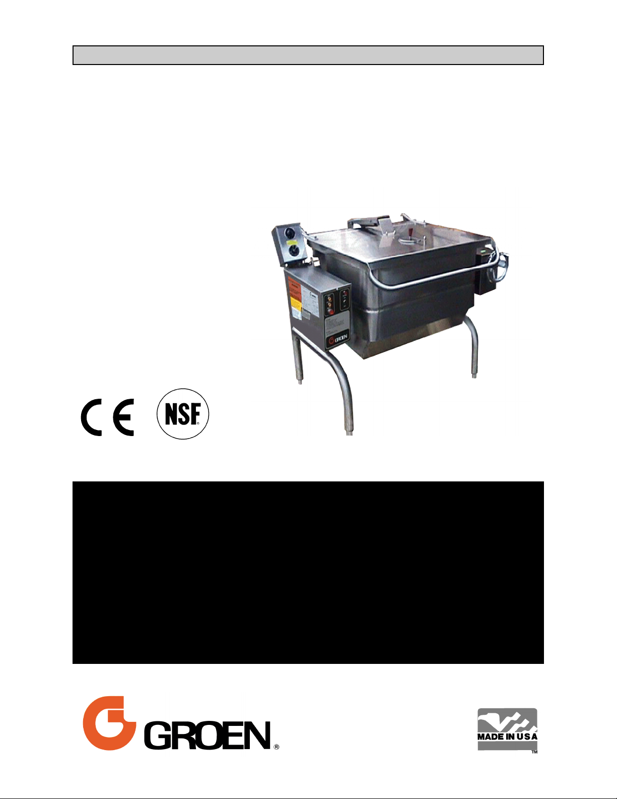
Braising Pan
Stainless Steel
Manual Tilting
Gas Heated
Floor Mounted
Stationary
THIS MANUAL MUST BE RETAINED FOR FUTURE REFERENCE. READ, UNDERSTAND AND
FOLLOW THE INSTRUCTIONS AND WARNINGS CONTAINED IN THIS MANUAL.
WARNING
DO NOT STORE OR USE GASOLINE OR OTHER FLAMMABLE VAPORS AND LIQUIDS IN THE
VICINITY OF THIS OR ANY OTHER APPLIANCE.
POST IN A PROMINENT LOCATION
INSTRUCTIONS TO BE FOLLOWED IN THE EVEN USER SMELLS GAS. THIS INFORMATION SHALL
BE OBTAINED BY CONSULTING YOUR LOCAL GAS SUPPLIER. AS A MINIMUM, TURN OFF THE
GAS AND CALL YOUR GAS COMPANY AND YOUR AUTHORIZED SERVICE AGENT. EVACUATE ALL
PERSONNEL FROM THE AREA.
WARNING
IMPROPER INSTALLATION, ADJUSTMENT, ALTERATION, SERVICE OR MAINTENANCE CAN
CAUSE PROPERTY DAMAGE, INJURY OR DEATH. READ THE INSTALLATION, OPERATING AND
MAINTENANCE INSTRUCTIONS THOROUGHLY BEFORE INSTALLING OR SERVICING THIS
EQUIPMENT.
.
Page 2

OSM-HFP/2E-CE
IMPORTANT — READ FIRST — IMPORTANT
THESE APPLIANCES MUST BE INSTALLED BY A COMPETENT PERSON IN CONFORMITY WITH THE
INSTALLATION AND SERVICING INSTRUCTIONS AND NATIONAL REGULATIONS IN FORCE AT THE TIME.
PARTICULAR ATTENTION MUST BE PAID TO THE FOLLOWING:
I. E. E. REGULATIONS FOR ELECTRICAL INSTALLATIONS
ELECTRICITY AT WORK REGULATIONS
GAS SAFETY (INSTALLATION & USE REGULATIONS
HEALTH AND SAFETY AT WORK ACT
FIRE PRECAUTIONS ACT
LOCAL AND NATIONAL BUILDING REGULATIONS
DETAILED RECOMMENDATIONS ARE CONTAINED IN INSTITUTE OF GAS ENGINEERS PUBLISHED
DOCUMENTS: IGE/UP/1, IGE/UP/2, BS6173 AND BS5440.
THESE APPLIANCES HAVE BEEN CE-MARKED ON THE BASIS OF COMPLIANCE WITH THE GAS
APPLIANCE DIRECTIVE, EMC AND LOW VOLTAGE DIRECTIVE FOR THE COUNTRIES, GAS TYPES AND
PRESSURES AS STATED ON THE DATA PLATE.
WARNING: TO PREVENT SHOCKS, ALL APPLIANCES WHETHER GAS OR ELECTRIC, MUST BE
EARTHED.
ON COMPLETION OF THE INSTALLATION, THESE INSTRUCTIONS SHOULD BE LEFT WITH THE
ENGINEER-IN-CHARGE FOR REFERENCE DURING SERVICING. FURTHER TO THIS, THE USERS
INSTRUCTIONS SHOULD BE HANDED TO THE USERS AND THE INSTALLER SHOULD INSTRUCT THE
RESPONSIBLE PERSON(S) IN THE CORRECT OPERATION AND MAINTENANCE OF THE APPLIANCE.
EMPHASIS SHOULD BE MADE WITH REGARD TO SAFE OPERATION OF DRAIN VALVE.
IT IS MOST IMPORTANT THAT THESE INSTRUCTIONS BE CONSULTED BEFORE INSTALLING AND
COMMISSIONING THE APPLIANCE. FAILURE TO COMPLY WITH THE SPECIFIED PROCEDURES MAY
RESULT IN DAMAGE OR THE NEED FOR A SERVICE CALL.
CAUTION: SHIPPING STRAPS ARE UNDER TENSION AND CAN SNAP BACK WHEN CUT.
CAUTION: UNIT WEIGHS 370 TO 560 LB. (165 TO 255 KG). FOR SAFE HANDLING, INSTALLER
SHOULD OBTAIN HELP AS NEEDED, OR EMPLOY APPROPRIATE MATERIALS HANDLING
EQUIPMENT (SUCH AS A FORKLIFT, DOLLY, OR PALLET JACK) TO REMOVE THE UNIT
FROM THE SKID AND MOVE IT TO THE PLACE OF INSTALLATION.
WARNING: INSTALLATION OF THE BRAISING PAN MUST BE DONE BY PERSONNEL QUALIFIED TO
WORK WITH GAS AND ELECTRICITY. IMPROPER INSTALLATION CAN RESULT IN INJURY
TO PERSONNEL AND/OR DAMAGE TO EQUIPMENT.
WARNING: THIS UNIT IS DESIGNED FOR COMMERCIAL USE. NEVER USE HOME OR RESIDENTIAL
GRADE GAS CONNECTIONS. THEY DO NOT MEET GAS CODES AND COULD BE
HAZARDOUS.
DANGER: ELECTRICALLY GROUND THE UNIT AT THE TERMINAL PROVIDED. FAILURE TO GROUND
UNIT COULD RESULT IN ELECTROCUTION AND DEATH.
WARNING: KEEP THE APPLIANCE AREA FREE AND CLEAR OF COMBUSTIBLE MATERIALS.
CAUTION: BE SURE ALL OPERATORS READ, UNDERSTAND AND FOLLOW THE OPERATING
INSTRUCTIONS, CAUTIONS AND SAFETY INSTRUCTIONS CONTAINED IN THIS MANUAL.
CAUTION: KEEP FLOORS IN BRAISING PAN WORK AREA CLEAN AND DRY. IF SPILLS OCCUR,
CLEAN IMMEDIATELY TO AVOID THE DANGER OF SLIPS OR FALLS.
WARNING: WHEN TILTING BRAISING PAN FOR PRODUCT TRANSFER:
1) USE CONTAINER DEEP ENOUGH TO CONTAIN AND MINIMIZE PRODUCT SPLASHING.
2) PLACE CONTAINER ON STABLE, FLAT SURFACE, AS CLOSE TO PAN AS POSSIBLE.
2
Page 3

OSM-HFP/2E-CE
3) STAND TO SIDE OF PAN WHILE POURING — NOT DIRECTLY IN POUR PATH OF HOT
CONTENTS.
4) RETURN PAN BODY TO LEVEL POSITION AFTER CONTAINER IS FILLED OR
TRANSFER IS COMPLETE.
5) DO NOT OVER FILL CONTAINER. AVOID DIRECT SKIN CONTACT WITH HOT
CONTAINER AND ITS CONTENTS.
WARNING: DO NOT HEAT AN EMPTY PAN FOR MORE THAN 5 MINUTES AT A SETTING HIGHER
THAN 300ºF (150ºC).
WARNING: IF THE PAN CONTAINS ITEMS IN SAUCE OR MELTED FAT, THEY CAN SLIDE FORWARD
SUDDENLY DURING TILTING AND CAUSE THE HOT LIQUID TO SPLASH OUT.
WARNING: AVOID ALL DIRECT CONTACT WITH HOT FOOD OR WATER IN THE PAN. DIRECT
CONTACT COULD RESULT IN SEVERE BURNS.
WARNING: KEEP WATER AND SOLUTIONS OUT OF CONTROLS AND BURNERS. NEVER SPRAY OR
HOSE THE CONTROL CONSOLE, OR ELECTRICAL CONNECTIONS.
CAUTION: MOST CLEANERS ARE HARMFUL TO THE SKIN, EYES, MUCOUS MEMBRANES AND
CLOTHING. PRECAUTIONS SHOULD BE TAKEN TO WEAR RUBBER GLOVES, GOGGLES
OR FACE SHIELD AND PROTECTIVE CLOTHING. CAREFULLY READ THE WARNINGS AND
FOLLOW THE DIRECTIONS ON THE LABEL OF THE CLEANER TO BE USED.
WARNING: THE CONTROL BOX IS NOT WATERPROOF. TAKE CARE TO KEEP WATER AND
CLEANING SOLUTIONS OUT OF THE BOX. NEVER HOSE OR SPRAY ELECTRICAL
CONTROLS, CONNECTIONS OR CONTROL CONSOLE.
WARNING: BEFORE REPLACING ANY PARTS, DISCONNECT THE UNIT FROM THE ELECTRIC POWER
SUPPLY AND CLOSE THE MAIN GAS COCK. ALLOW FIVE MINUTES FOR UNBURNED GAS
TO VENT.
CAUTION: USE OF ANY REPLACEMENT PARTS OTHER THAN THOSE SUPPLIED BY GROEN OR
AUTHORIZED DISTRIBUTORS CAN CAUSE INJURY TO THE OPERATOR AND DAMAGE TO
THE EQUIPMENT AND WILL VOID ALL WARRANTIES.
IMPORTANT: Service performed by other than factory authorized personnel will void all warranties.
3
Page 4

OSM-HFP/2E-CE
Table of Contents
IMPORTANT OPERATOR WARNINGS (READ FIRST) .............................................2
REFERENCES ............................................................................. 4
EQUIPMENT DESCRIPTION .................................................................5
1. INSTALLATION .........................................................................5
2. ASSEMBLY AND COMMISSIONING ........................................................8
3. SERVICING AND CONVERSION ..........................................................10
3.16 WIRING DIAGRAM ..............................................................14
4. USER INSTRUCTIONS ..................................................................15
5. CLEANING ...........................................................................16
6. SAFETY PRECAUTIONS ................................................................17
7. MAINTENANCE ........................................................................ 18
8. TROUBLESHOOTING ...................................................................19
9. PARTS LIST .......................................................................... 20
10. SERVICE LOG ........................................................................26
11. WARRANTY ..........................................................................27
References
American Gas Association Laboratories
8501 East Pleasant Valley Rd.
Cleveland, Ohio 44131
Z223.1-1984 National Fuel Gas Code
American National Standards Institute
1403 Broadway
New York, New York 10018
Canadian Gas Association
55 Scarsdale Road
Don Mills, Ontario M3B 2 R3
ECOLAB, INC.
370 Wabasha
St. Paul, Minnesota 55102
National Fire Protection Association
60 Battery March Park
Quincy, Massachusetts 02269
NFPA/54 Installation of Gas Appliances & Gas
Piping
NFPA/70 The National Electrical Code
NFPA/96 Ventilating Hoods
National Sanitation Foundation
3475 Plymouth Road
Ann Arbor, Michigan 48106
Underwriters Laboratories, Inc.
333 Pfingsten Road
Northbrook, Illinois 60062
ZEP Manufacturing
1390 Lunt Avenue
Elk Grove Village, Illinois 60007
4
Page 5

OSM-HFP/2E-CE
Equipment Description
The following dimensions apply to CE model HFP braising pans:
Model Width Depth Height Weight (Kg) Weight (lbs)
HFP/2E-3/2E-3 1245 mm 960 mm 1780 mm 241 530
HFP/2E-4/2E-4 1500 mm 960 mm 1780 mm 270 593
Groen Gas Heated Braising Pans provide a stainless steel pan equipped with patented heat transfer fins,
burner/combustion chamber, hand-operated tilting mechanism, thermostatic controls, and hinged cover. The
Braising Pan serves as braising unit, griddle, fry pan, oven, kettle, bain-marie, or food warmer and server, and it
can be adapted for use as a steamer.
The pan body is made from heavy-duty stainless steel welded into one solid piece, with a polished interior and
exterior. A pouring lip is welded to the front wall. The cooking surface is a stainless steel clad plate fitted with
welded heat transfer fins which assure uniform heat transfer over the entire surface. The gas burner/combustion
chamber supplies the heat.
An easily-operated worm and gear mechanism tilts the pan and provides precise control for pouring or dumping
the contents of the pan. This hand-wheel controlled mechanism is located in a stainless steel console to the right
of the pan body. To assist cleaning, the pan body can be tilted past the vertical position. When the pan is tilted, the
burners shut off automatically.The thermostat provides automatic control of cooking temperature. Operating the
thermostat dial on the front of the control console turns the heat on or off and sets the pan temperature.
A vented, heavy gauge, one-piece, stainless steel cover with a condensate drip shield on the rear edge is standard
on the Braising Pan. A fully enclosed, spring type actuator counter-balances the cover to keep it in either the
opened or closed position. The cover opens to the back and is hinged to the frame, so it moves independently of
the pan body.
Options available with the listed models are:
1. Fill faucet with swing spout.
2. Caster mounting kit.
3. Fold-down work tray (pan support) mounted on left or right side. (Factory installed option)
4. 2” Tangent draw-off. (Factory installed option)
5. Model REJ Steamer Insert set.
6. Steamer pan Carrier.
7. Quick gas disconnect with restraining cable
1. Installation
The following information pertains to the CE model HFP/2E, and replaces or augments the information provided in
OM-HFP. These appliances must be installed by a competent person in conformity with the installation and
servicing instructions and national regulations in force at the time. Particular attention must be paid to the
following:
I. E. E. Regulations for Electrical Installations
Electricity at Work Regulations
Gas Safety (Installation & Use Regulations
Health and Safety at Work Act
Fire Precautions Act
Local and National Building Regulations
Detailed recommendations are contained in institute of gas engineers published documents: IGE/UP/1, IGE/UP/2,
BS6173 AND BS5440.
5
Page 6

OSM-HFP/2E-CE
1.1 Installing Clearances
Minimum clearance of 0 mm from the sides and 150
mm from the rear of the appliance are required if the
appliance is installed next to combustible surfaces.
Vertical clearance of at least 1000 mm should be
allowed between the top edge of the flue outlet and
any overlying surface.
Adequate ventilation, whether natural or
mechanically induced, must be provided to ensure a
supply of fresh air for gas combustion, and to
facilitate effective removal of the products of
combustion.
Ventilation recommendations for catering appliances
are provided in BS 5440 : 2. Furthermore, guidance
on the column of ventilation air required for different
types of catering equipment to ensure sufficient
room ventilation is provided at right.
For multiple installations, the requirements for
individual appliances should be added together.
Installation should be made in accordance with local
and national regulations applying at the time. A
competent installer must be employed.
The appliance flue discharges horizontally from the
rear of the unit. It must not be directly connected to
any flue, mechanical extraction system, ducting, etc.,
which leads to the outside of the building. The
appliance is best discharged under an open canopy
connected with a ventilating system.
1.2 Gas Supply
Incoming service must be of sufficient size to supply
full rate without excessive pressure drop. A gas
meter is connected to the service pipe by the gas
supplier.
Any existing meter should be checked by the
supplier to ensure that the meter has the capacity for
passing the required rate of gas for the braising pan
in addition to any other gas equipment installed.
EQUIPMENT
Ventilation Rate Required
m³/min ft³/min
Range, Unit Type 17 600
Pastry Oven 17 600
Fryer 26 900
Grill 17 600
Steak Grill 26 900
Boiling Pan 17 600
Steamer 17 600
Sterilizing Sink 14 500
Bain-Marie 11 400
Tea/Coffee Machine 8.5-14 300-500
The appliance governor is incorporated in the gas
control valve which is situated in the left control
cabinet. The control valve governor is suitable for
both natural and propane gases without conversion.
Installation pipework should be fitted in compliance
with IEGE/UP/2. The pipework should not be smaller
than the gas inlet connection (Rp½ [½” B.S.P.]).
An isolating cock must be located close to the
appliance to allow shut-down during emergencies or
service. Installation must be tested for gas
soundness and purged as specified in IGE/UP/1.
1.3 Electrical Supply
This unit is designed for connection to fixed wiring.
A suitably rated isolating switch with contact
separation of at least three millimeters on both poles,
must be fitted to the installation. The wiring must be
executed in accordance with the regulations listed
inside the cover page of this manual supplement.
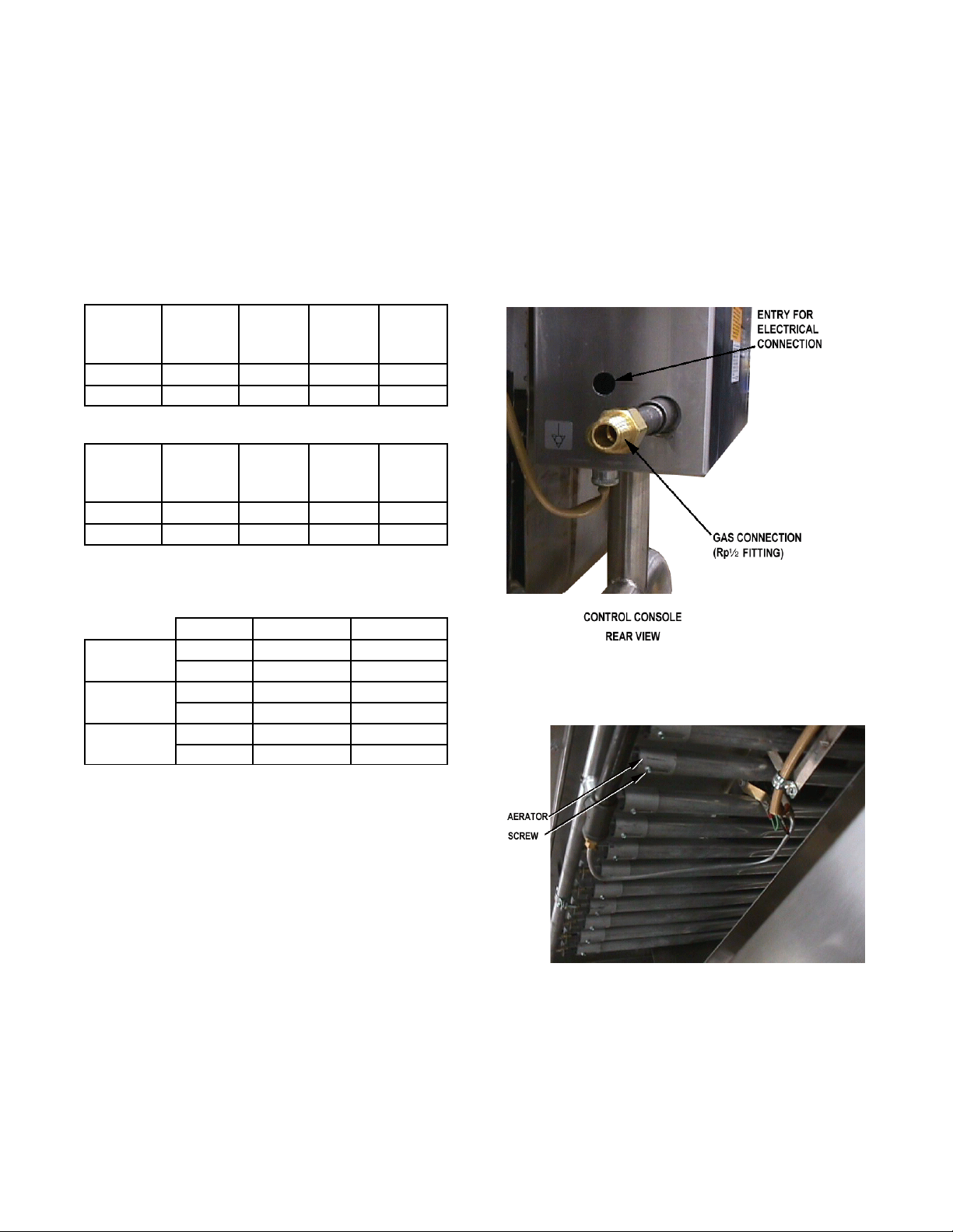
Cable entry is at the control box on the rear left side
of the appliance. Access to the terminals is gained
by removing top and side panels as described in
Paragraphs 3.3.1 and 3.3.2. Power is brought in
through the back to the base of the terminal block,
where it is connected.
WARNING
THIS APPLIANCE MUST BE EARTHED.
6
Page 7
OSM-HFP/2E-CE
1.4 Water Supply
Not applicable to these appliances.
1.5 Gas System Performance
The tables below provide the total Gas Rates,
Injector Diameters and Pressure Adjustments for
model HFP/2-CE using natural (G20 & G25) and
propane (G30) gas sources.
Total Gas Rate
Natural
Model
HFP/2E-3
HFP/2E-4
Injector Diameters-Natural & Propane Gas
Model
HFP/2E-3
HFP/2E-4
(G20&
G25) KW
27.5 93,900 27.5 93,900
39.0 133,100 39.0 133,100
Natural
Gas G20
(mm)
1.4 1.5 0.89 13
1.4 1.59 0.89 18
Natural
BTU/hr
Natural
Gas G25
(mm)
Propane
(G31)
KW
Propane
Gas G31
(mm)
Propane
BTU/hr
No. of
Orifices
(Injectors)
Use of the appliance with non-approved gases in a
listed country, or use in other countries will void CE
certification.
1.6 Burner Adjustment
The burner primary airflow may be adjusted by
loosening the screw and sliding the aerator forward
or backward. (See photograph)
Gas Pressure Adjustment
A pressure test point is fitted on the burner manifold
and on the gas control valve.
Model HFP/2E-3 HFP/2E-4
NATURAL
GAS G20
NATURAL
GAS G25
PROPANE
GAS G31
NOTE: With reference to the gas rate, pressure
adjustments and conversions, this appliance is
CE-approved for use with the following gases:
a) G20 natural gas may be supplied to the
appliance in Austria, Belgium, Denmark,
Finland, France, Germany, Greece, Iceland,
Ireland, Italy, Luxembourg, Norway, Portugal,
Spain, Sweden, Switzerland and the United
Kingdom.
b) G25 natural gas may be supplied to the
appliance in Belgium, France and the
Netherlands.
mbar 7 8.75
in. WC 2.81 3.51
mbar 7 7
in. WC 2.81 2.81
mbar 20 20
in. WC 8.03 8.03
Gas is connected at the rear of the control
console.
Each burner may be adjusted by loosening the
screw and sliding the aerator forward or back.
c) G31 propane gas may be supplied to the
appliance in France, Germany, Ireland, the
Netherlands, Portugal, Spain, Switzerland,
and the United Kingdom.
7
Page 8
OSM-HFP/2E-CE
2. Assembly and Commissioning
2.1 Electrical Supply
Before commissioning the appliance, ensure that the
electrical installation has been performed in
compliance with relevant regulations. See
Paragraph 1.3, above.
THIS APPLIANCE MUST BE EARTHED.
WARNING
2.2 Pre-Commissioning Check
a) Remove literature and packing materials from
the interior and exterior of the unit.
b) Put enough water into the pan to cover the
bottom to a depth of ¼ to ½ inch. With the pan
body in the horizontal position, note how the
water lies in the pan, to confirm that the pan was
leveled properly during installation.
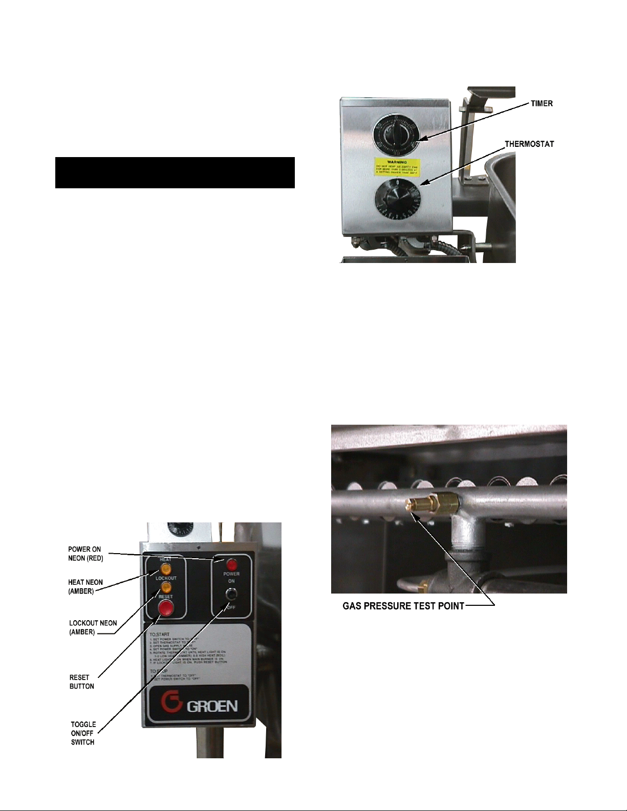
2.3 Operating the Braising Pan
2.3.1 Lighting Sequence
a) Put water in the pan (6 to 12 mm deep)
b) Check that gas and electricity mains are on.
c) Turn the toggle switch (Main Control Box) to the
“ON” position. The power neon (Main Control
Box) will illuminate.
d) Turn the thermostat (Upper Control Box) to the
desired setting.
Upper Control Box
f) Should the unit fail to light, it will lock-out, and
the lockout neon will illuminate (Main Control
Box). Turn the unit off and wait for one or two
minutes before attempting to switch it on again.
g) Repeat steps b through e.
h) To switch off the unit, put the toggle switch in the
Off position.
i) Turn gas and electricity mains off.
2.3.2 Setting the Gas Pressure
e) Observe that the burners light by the lighting of
the heat neon (Main Control Box) (approximately
10-15 seconds).
Main (Lower) Control Box
Connect a gauge to check pressure at the gas
manifold.
a) During commissioning, a gas pressure check is
essential. Connect a suitable pressure gauge to
the gas manifold to perform this test. The
pressure gauge should be connected to the test
nipple (See photograph above).
b) Turn the gas and electricity mains on.
8
Page 9
c) Light the burners as described in Paragraph
2.3.1, above.
d) Manifold gas pressure should be as noted in
Section 1.5 of the manual. If adjustment is
necessary, follow steps e through j, below.
e) Remove the screws which secure the control
cabinet lid and remove the control cabinet side
panel.
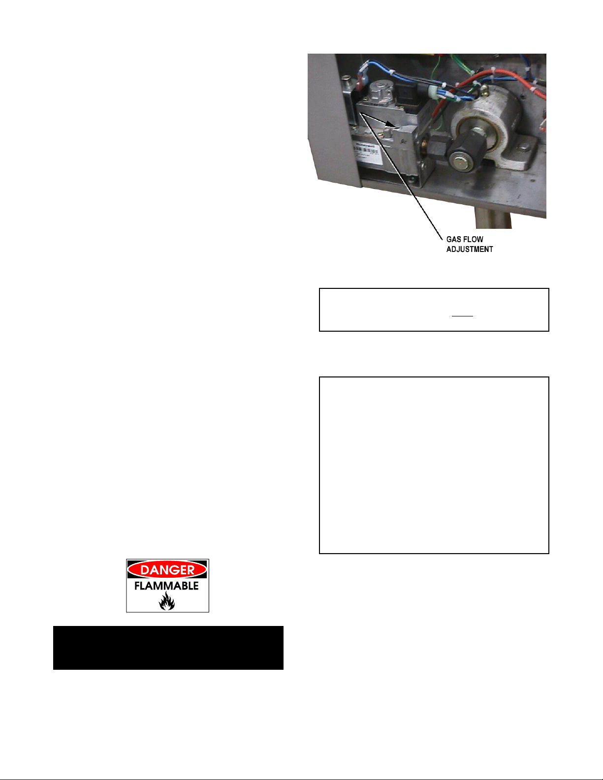
f) Remove the governor cap screw on the gas
control valve to gain access to the screw inside
the turret. (See photograph at right)
g) The governor is suitable for both natural and
propane gas.
OSM-HFP/2E-CE
h) Turn the screw inside the turret clockwise to
increase the pressure, anti-clockwise to reduce
it. Check the burner pressure again after 15
minutes operation, and adjust if necessary.
i) Disconnect the pressure gauge from the test
point. Reseal the test point and test for gas
soundness.
j) Replace governor cap screw, and replace
control box panel and lid.
2.3.3 Checking Performance of Controls
a) Light the unit as described in Paragraph 2.3.1,
above. Check that the controls produce a
healthy spark from the electrode to the earthing
post, and that ignition is smooth and without
delay.
b) Turn the thermostat off and then on. Check that
the burners go out when the thermostat is turned
off, and that they reignite smoothly when it is
switched back on. Repeat several times.
c) Fill the pan with unused oil up to the mark in the
pan.
Adjust flow by turning the screw on the gas valve
governor.
CAUTION
THE TEMPERATURE MUST NOT EXCEED 200ºC
OR THE HIGH LIMIT THERMOSTAT WILL TRIP.
e) If the unit fails to operate as described, the unit
should be serviced by an Engineer.
IMPORTANT
These appliances must be installed by a competent
person in conformity with the installation and
servicing instructions and national regulations in
force at the time. Particular attention must be paid
to the following:
I. E. E. Regulations for Electrical Installations
Electricity at Work Regulations
Gas Safety (Installation & Use Regulations
Health and Safety at Work Act
Fire Precautions Act
Local and National Building Regulations
Detailed recommendations are contained in institute
of gas engineers published documents: IGE/UP/1,
IGE/UP/2, BS6173 AND BS5440.
WARNING
DO NOT OVERFILL WITH OIL OR FIRE MAY
RESULT!
d) Set the thermostat knob at “10" and allow the oil
to heat up. Immerse a thermometer or
thermocouple 25 mm below the oil surface at the
center of the pan. Check that the temperature
stabilizes at 190ºC, (± 5ºC).
2.4 Instructions to Installer
IMPORTANT: After installing and commissioning
the appliance, the User’s Instructions should be
handed to the user or purchaser. Ensure that the
instructions for lighting, turning off, correct use
and cleaning are properly understood.
Emphasize the location of the main gas isolating
valve and demonstrate the emergency shut
down procedure.
9
Page 10

OSM-HFP/2E-CE
3. Servicing and Conversion
3.1 Servicing
IMPORTANT
BEFORE ATTEMPTING ANY SERVICING, ENSURE
THAT THE ISOLATING COCK IS TURNED OFF AND
CANNOT BE INADVERTENTLY TURNED ON.
ENSURE ALSO THAT THE ELECTRICITY SUPPLY IS
DISCONNECTED.
AFTER ANY SERVICING OR EXCHANGE OF GAS
CARRYING COMPONENTS — ALWAYS CHECK
FOR GAS SOUNDNESS!
Note: When replacing wiring connections refer to
the wiring diagram in the unit or this manual.
3.1.1 After Servicing
a) Test for gas soundness as specified in IGE/UP1
as appropriate after any gas connection has been
disturbed.
b) Check for correct operation as appropriate (see
Installation, Section 1.5).
3.1.2 Regular Servicing Procedures
The following must be checked at regular intervals:
a) Burners
Clean the burners periodically to maintain
maximum performance. Burners are best
cleaned with a stiff bristle brush, or if necessary
with a wire brush. Take care not to damage the
burner.
Clean the injector orifice with a wooden splinter or
toothpick. Avoid metal reamers, which may
distort or increase the orifice size.
b) Gears
The gear housing has been fitted for proper
lubrication of moving parts. Since the gears do
not run in oil, periodic lubrication with grease is
essential. Frequency of lubrication depends on
operating conditions, but should occur at least
once every six months. Groen recommends the
use of a Number Two grade LGI lithium grease.
Add grease through the Zerk fittings on the gear
housing until grease flows out of the bearings
around the trunnion shaft. Place a liberal amount
of grease on the gear to cover the arc that is in
contact with the worm gear.
3.2 Conversion — NOTE: See Para 1.5 (Page 7)
for important gas conversion information.
VERIFY THE TYPE OF GAS TO BE USED. In
the countries listed in Paragraph 1.5 all
conversions must be for approved gas.
To change the type of gas used (e.g. G20 to G25 or
G31 or the like), change the following:
Burner injector
Pilot orifice
Pressure setting
Data Plate
The governor spring does not need to be changedonly the pressure setting.
3.3 Removal of Control Panels
3.3.1 Removal of Control Cabinet Lid
a) Remove the two screws which secure the lid to
the control cabinet around its edge.
b) Remove the lid.
c) Replace in reverse order
3.3.2 Removal of Control Cabinet Side Panel
a) Remove lid as described above.
b) Lift off the removable side panel.
c) Replace in reverse order
3.3.3 Removal of Upper Control Box Panels
a) Remove thermostat knob and timer knob.
b) Remove screw from bottom of panel.
c) Remove panel.
d) Repeat steps (b) and (c) for back panel.
e) Replace in reverse order.
3.4 Removal of Spark Ignition Module
(Turn gas and electricity mains off)
a) Remove control panel lid and side cover as
described in Paragraph 3.3.1 and 3.3.2, above.
b) Disconnect electrical leads from spark ignition
module.
10
Page 11

OSM-HFP/2E-CE
c) Remove retaining screws securing spark ignition
module.
d) Withdraw spark ignition module from control
compartment.
e) Replace in reverse order.
3.5 Removal of Tilt Switch (Turn gas and
electricity mains off)
a) Remove upper control panel front and rear covers
as described in Paragraph 3.3.3, above.
b) Disconnect electrical leads from tilt switch.
c) Remove tilt switch from the spring clip.
d) Withdraw the tilt switch from control
compartment.
e) Replace in reverse order.
3.6 Removal of Gas Control Valve (Turn
gas and electricity mains off)
a) Remove control panel lid and side panel as
described in Paragraph 3.3.1 and 3.3.2, above.
b) Disconnect electrical leads from gas control
valve.
c) Undo and remove inlet gas pipe from gas control
valve
d) Remove the spring clip which secures the
trunnion gas fitting.
e) Remove the control valve from control
compartment.
f) Replace in reverse order.
3.7 Removal of On/Off Switch and
Reset Button (Turn gas and electricity
mains off)
a) Remove control panel lid and side panel as
described in Paragraph 3.3, above.
b) Disconnect electrical leads from On/Off switch or
Reset button.
11
Page 12

OSM-HFP/2E-CE
c) Undo and remove the retaining collar which
secures the On/Off switch to the outer surface of
the control cabinet, and/or which secures the
Reset button to the inner surface of the control
panel.
d) Withdraw the On/Off switch or the Reset button
from control compartment.
a) Fill the pan with unused oil to the indicated mark.
Place a thermocouple 25 mm below the oil
surface in the middle of the pan.
e) Replace in reverse order.
3.8 Removal of Neons (Turn gas and
electricity mains off)
a) Remove control panel lid and side panel as
described in Paragraph 3.3.1 and 3.3.2, above.
b) Disconnect the neons’ flying leads.
c) Undo and remove the retaining collar which
secures the neon to the control cabinet.
d) Withdraw the neon from the control compartment.
e) Replace in reverse order.
3.9 Removal of Operating Thermostat
(Turn gas and electricity mains off)
To Replace
a) Remove upper control box panels as described in
Paragraph 3.3.3, above.
b) Remove thermostat from front panel.
WARNING
DO NOT OVERFILL WITH OIL OR FIRE MAY
RESULT!
b) Remove the control knob and place a
screwdriver down the centre of the spindle.
c) Light the unit and allow the oil to heat.
d) Adjust the thermostat by turning the screwdriver
clockwise to decrease, and anti-clockwise to
increase temperature. Ensure that the
temperature settles at 190ºC (±5ºC). (Note:
Thermostat may cycle seven or eight times
before oil temperature settles at 190ºC).
e) Replace control knob.
3.10 Removal of High Limit Thermostat
(Turn gas and electricity mains off)
This device is set to shut off the flow of gas to the
burners to prevent oil temperature from exceeding
230ºC. Manual intervention is required to reset the
control in the event of a lockout.
c) Remove electrical leads from operating
thermostat.
d) Remove operating thermostat phial from the
underside of the pan, and remove retaining clips.
e) Remove the retaining clip which secures the
flexible conduit to the pan side.
f) Pull thermostat phial through the flexible conduit
(or cut if scrap).
g) Replace in reverse order.
To Calibrate
If calibration is required, use the following
procedures:
Both the Operating Thermostat and the High Limit
Thermostat connect to the braising pan by means
of flexible conduit. (Rear of Upper Control Box)
12
Page 13

OSM-HFP/2E-CE
To Reset
Remove the upper control box rear panel as
described in 3.3.3, above. Push the reset button on
the body of the high limit thermostat.
To Replace
a) Remove high limit thermostat following the same
procedure as for the operating thermostat
(Paragraph 3.9, above)
b) Replace in reverse order following the same
procedures.
To Check Operation
Operation of the high limit thermostat must be
checked regularly. Use the following procedure:
a) Remove the upper control box from panel as
described in Paragraph 3.3, above.
b) Fill the pan with unused oil to the indicated mark.
Place a thermocouple or thermometer 25 mm
below the oil surface in the middle of the pan.
f) If the high limit thermostat switches, but not at the
specified temperatures, the thermostat requires
replacement. Rejected thermostats must be
logged and returned.
g) To remove, see replacement procedures above.
NOTE: After this test, reconnect the regulating
thermostat wires.
Calibration
The high limit thermostat is of the fixed type. Its
calibration point may not be adjusted.
WARNING
IF THE HIGH LIMIT THERMOSTAT FAILS TO CUT
OFF AT 230ºC IMMEDIATELY TURN OFF THE
GAS SUPPLY. CONDUCT AN INVESTIGATION
TO DETERMINE THE FAULT, AND CORRECT IT
BEFORE USING THE APPLIANCE AGAIN.
3.11 Removal of Burners (Turn gas and
electricity mains off)
a) Undo and remove the front two retaining nuts of
the burner guard.
WARNING
DO NOT OVERFILL WITH OIL OR FIRE MAY
RESULT!
c) Ensure that the electrical power is off before
continuing. Disconnect the leads from the
operating thermostat. Connect the leads together
using the terminal block. This effectively removes
the operating thermostat from the circuit. It may
also be bypassed with a jumper across the
thermostat terminals.
d) Switch the unit back on and light the unit as
described in the lighting instructions, above. The
burners will light and heat up the pan.
DO NOT LEAVE THE APPLIANCE DURING THIS
TEST.
e) If the high limit thermostat is functioning correctly,
the gas supply will cut off as the temperature
reaches 205 to 225ºC. Once the high limit
thermostat has tripped, switch off the mains
electricity. Reconnect the operating thermostat
and replace all panels.
b) Undo the two retaining nuts at the side of the
burner guard. Do not fully remove. The burner
guard will swivel back to allow access to the
burners.
c) Undo and remove the retaining screws holding
the burners.
d) Remove burner.
e) Replace in reverse order.
3.12 Removal of Ignition Electrode (Turn
gas and electricity mains off)
a) Disconnect electrical leads from ignition
electrode.
b) Remove ignition electrode from bracket.
c) Replace ignition electrode.
d) Replace electric leads.
e) Check that the distance between the igniter and
burner is within specified tolerances. Ensure
that smooth, rapid ignition is achieved once the
new spark igniter is in place.
3.13 Removal of Sensing Electrode
(Turn gas and electricity mains off)
13
Page 14

OSM-HFP/2E-CE
a) Disconnect sensing electrode electrical leads.
b) Remove sensing electrode from bracket.
c) Replace sensing electrode.
d) Replace electric leads.
e) Ignite burners. Ensure that the sensing electrode
is properly positioned in the burner flame and that
burners remain lit. If the burners go out, adjust
the sensing electrode to suit.
3.14 Removal of Burner Orifices
(Injectors) (Turn gas and electricity
mains off)
a) Remove burners (Paragraph 3.11).
3.16 Wiring Diagram, HFP/2-E CE Model
b) Remove orifices from burner manifold.
c) Replace in reverse order.
3.15 Fuse Replacement
a) Remove the control cabinet lid and side as
described in Paragraph 3.3.1 and 3.3.2
b) Remove fuse from fuse holder. (See
photograph, Page 11).
c) Replace fuse with an identical fuse.
d) Replace in reverse order.
14
Page 15

4. User Instructions
OSM-HFP/2E-CE
4.1Lighting and Operation
a) Check that gas and electricity mains are on.
b) Turn the toggle switch (Main Control Box) to the
“ON” position. The power neon (Main Control
Box) will illuminate.
c) Turn the thermostat (Upper Control Box) to the
desired setting.
d) Observe that the burners light by the lighting of
the heat neon (Main Control Box) (approximately
10-15 seconds).
e) Should the unit fail to light, it will lock-out, and the
Lockout neon will illuminate (Main Control Box).
Turn the unit off and wait for one or two minutes
before attempting to switch it on again.
f) Press the Reset Button once.
g) Repeat steps b through e.
CAUTION
IF THE RESET LIGHT COMES ON REPEATEDLY,
DO NOT OPERATE THE APPLIANCE. CALL FOR
SERVICE OR A QUALIFIED PERSON TO
INVESTIGATE.
For frying, the depth of oil in the pan must never
exceed the maximum oil level mark on the inner
pan wall.
WARNING
DO NOT OVERFILL WITH OIL OR FIRE MAY
RESULT.
4.4 Users’ Thermostat
Provides automatic control of the braising pan
temperature at selected temperatures up to a
maximum of 190ºC.
4.5 Sequence of Operation
The following “sequence of operation” is provided to
help the user understand how the unit functions.
a) Switching the On/Off switch to the On position to
start the appliance causes the power neon to
illuminate.
b) Turning the thermostat sends a signal to the
ignition module.
4.2 To Shut Down Braising Pan
a) Turn thermostat dial to the Off position.
b) Switch the On/Off switch to the Off position.
c) For a prolonged shut down —
— Follow steps a and b
— Turn the gas and electricity mains off
d) Turn the tilting handle clockwise to pour out the
water or contents.
4.3 Filling the Braising Pan
Using hot water and detergent, clean out the pan
thoroughly prior to operation.
The pan should not be overfilled, and an allowance
should always be made for expansion and foaming of
the food being cooked.
c) The ignition module opens the multi-functional
control valve which allows gas to flow at a low
rate to the main burner. It simultaneously starts
a sparking sequence at the burner.
d) The spark ignites the main burner on low flow.
Once this occurs, the flame sensing probe
detects the flame. This confirms that lighting has
been successful.
e) The sparking/ignition sequence shuts off, and the
“Heat” neon illuminates.
f) After a short period of time the multi-functional
control valve opens to full flow and brings the
burners up to their maximum rate.
g) If, however, a burner flame is not detected within
15 seconds, the ignition module goes into lockout mode, and the lockout neon is lit.
h) To restart the ignition sequence the unit must be
reset by depressing the Reset button on the front
of the control cabinet.
i) In addition to the gas lockout, other safety
features include:
15
Page 16

OSM-HFP/2E-CE
— A high limit safety thermostat which cuts off
the gas supply should the operating
thermostat fail (i.e., should the temperature
exceed operating limits).
— A tilt switch which automatically cuts off the
gas supply when the unit is tilted when in
operation.
j. When the pan reaches a set temperature, the
thermostat switch opens. This halts the signal to
the gas control valve and causes the valve to
shut off the flow of gas.
k) When the pan cools below its set temperature,
the thermostat switch closes and starts another
heating cycle. This on-off cycling continues,
keeping the pan at the desired temperature.
4.6 To Empty the Pan
Turn the hand crank on the front of the cabinet
clockwise to tilt the pan body forward. The pan will
stay in position when you stop turning the handle. To
return it to the upright position, turn the crank anticlockwise.
WARNING
DO NOT STAND IN FRONT OF THE PAN WHEN
TILTING IT. BE CAREFUL TO KEEP HOT
CONTENTS FROM SPILLING. KEEP PEOPLE
AWAY FROM WHEN EMPTYING THE PAN.
4.7 Power Failure
a) If power to the unit is lost, do not attempt to
operate the appliance until the electricity has
been restored.
b) When the power comes on again, follow the
steps in Paragraph 4.1, Lighting and Operation.
5. Cleaning
WARNING
DISCONNECT ELECTRICAL SUPPLY BEFORE ANY CLEANING. KEEP WATER AND SOLUTIONS OUT OF
CONTROLS AND BURNERS. NEVER SPRAY OR HOSE THE CONTROL CONSOLE OR ANY ELECTRICAL
CONNECTIONS.
1. Before any cleaning operation, shut off the
burner by turning the thermostat dial to "OFF". If
water or cleaning solution will be sprayed, unplug
the unit from the electric power source, or shut
off the power at the circuit breaker or fuse panel.
2. Clean all food-contact surfaces soon after use,
before the pan has cooled completely. If the unit
is in continuous use, thoroughly clean and
sanitize both interior and exterior at least once
every 12 hours.
3. Scrape or rinse out large amounts of food
residues, then wash the inside of the pan body
with a mixture of hot water and soap or an
appropriate detergent, such as Mikro-Quat from
ECOLAB. Follow the detergent supplier's
recommendations on strength of the solution to
use. Rinse the pan thoroughly with hot water and
drain completely.
MOST CLEANERS ARE HARMFUL TO THE SKIN,
EYES, MUCOUS MEMBRANES AND CLOTHING.
PRECAUTIONS SHOULD BE TAKEN TO WEAR
RUBBER GLOVES, GOGGLES OR FACE SHIELD
AND PROTECTIVE CLOTHING. CAREFULLY
READ THE WARNINGS AND FOLLOW THE
DIRECTIONS ON THE LABEL OF THE CLEANER
TO BE USED.
4. To remove materials stuck to the equipment, use
a brush, sponge, cloth, plastic or rubber scraper,
or plastic wool along with the detergent or soap
solution. To minimize the effort required in
washing, let the detergent solution sit in the pan
and soak into the residue, or heat the detergent
solution briefly in the pan. Do NOT use any
abrasive materials or metal implement that might
scratch the surface, because scratches make the
pan hard to clean and provide places for bacteria
to grow. Do NOT use steel wool, which may
leave particles imbedded in the pan surface and
cause eventual corrosion and pitting.
CAUTION
16
Page 17

OSM-HFP/2E-CE
4. As part of the daily cleaning program, clean all
external and internal surfaces that may have
been soiled. Remember to check such parts as
the underside of the cover, control console, etc.
6. Controls and the control console may be cleaned
with a damp cloth.
7. The exterior surface of the unit may be polished
with a recognized stainless steel cleaner, or with
water and detergent.
8. If the equipment needs to be sanitized, use a
sanitizing solution equivalent to one that supplies
200 parts per million available chlorine. Obtain
advice on the best sanitizing agent from your
supplier of sanitizing products. Following the
supplier's instructions, apply the sanitizing agent
after the unit has been cleaned and drained.
Rinse off the sanitizer thoroughly.
NOTICE
NEVER LEAVE A CHLORINE SANITIZER IN
CONTACT WITH STAINLESS STEEL SURFACES
LONGER THAN 30 MINUTES. LONGER
CONTACT CAN CAUSE CORROSION.
9. If there is difficulty removing mineral deposits or
a film left by hard water or food residues, clean
the pan thoroughly and then use a deliming
agent, such as Groen De-limer De-Scaler (Part
Number 114800) or Lime-Away from ECOLAB, in
accordance with manufacturer directions. Rinse
and drain the unit before further use.
10. If especially difficult cleaning problems persist,
contact your cleaning product representative for
assistance.
Don’t use metal implements or steel wool to
clean the braising pan.
Use a brush, cloth, sponge or other non-abrasive
tool for cleaning.
6. Safety Precautions
A stop-cock will be fitted in the gas pipe supplying the appliance. The user must be familiar with its location and
operation, and able to turn it off in an emergency.
If there is a smell of gas, immediately turn off the gas, ventilate the area, and call the gas supplier.
NEVER USE NAKED FLAME TO SEARCH FOR GAS LEAKS.
17
Page 18

OSM-HFP/2E-CE
7. Maintenance
Your Braising Pan is designed to require minimum
maintenance, but certain parts may need
replacement after prolonged use. After installation,
no user adjustment should be necessary. If a service
need arises, only authorized personnel should
perform the work.
WARNING
ELECTRIC POWER ALWAYS SHOULD BE
SHUT OFF BEFORE WORK IS DONE ON
INTERNAL COMPONENTS.
Service personnel should check the unit at least once
a year. This periodic maintenance should include
inspecting electrical wires and connections, cleaning
the inside of the control
console, and possible adjustment of the pilot light. At
least twice a year, grease the two trunnion bearings.
(See Paragraph 3.1.2.b Gears).
WARNING
DISCONNECT ELECTRICAL POWER FROM
THE UNIT BEFORE ATTEMPTING TO
GREASE THE TRUNNION BEARINGS.
A Service Log is provided with the warranty
information at the back of this manual. Each time
service is performed on your Groen equipment, enter
the date on which the work was done, what was
done, and who did it. Keep the manual with the
equipment for quick and easy reference.
18
Page 19

OSM-HFP/2E-CE
8. Troubleshooting
Your Groen Braising Pan will operate smoothly and efficiently if properly maintained. However, the following is a list
of checks to make in the event of a problem. If the actions suggested do not solve the problem, call your qualified
Groen Service Representative. For the phone number of the nearest agency, call your area Groen representative
or the Groen Parts and Service Department. If an item on the list is followed by Y, the work should only be
performed by a qualified service representative.
WARNING
BEFORE REPLACING ANY PARTS, DISCONNECT THE UNIT FROM THE ELECTRICAL POWER SUPPLY AND
CLOSE THE MAIN GAS VALVE. ALLOW FIVE MINUTES FOR GAS TO VENT.
USE OF ANY REPLACEMENT PARTS OTHER THAN THOSE SUPPLIED BY GROEN OR THEIR AUTHORIZED
DISTRIBUTORS CAN CAUSE INJURY TO THE OPERATOR AND DAMAGE TO THE EQUIPMENT AND WILL
VOID ALL WARRANTIES.
Important: Service performed by other than factory authorized personnel will void all warranties.
SYMPTOM WHO
System does not produce a
spark
Spark is present but the pilot
will not light.
Pilot lights, but main burner
will not come on and spark
does not stay on.
Auth Service
Rep Only
Auth Service
Rep Only
Auth Service
Rep Only
X indicates items which must be performed by an authorized technician.
a. Thermostat, and close the contacts if they are open X
b. AC voltage between terminals on secondary side of transformer.
If it is not 24 Volt, replace the transformer X
c. That the high tension cable is in good condition. If cracked or
brittle, replace. X
d. Pilot electric ceramic for crack or break. X
e. Pilot spark gap. Regap. X
a. That the pilot valve is securely connected to terminals. X
b. For 24 VAC at terminals PV and PV/MV. If 24V is not present,
replace the ignition control module. X
b. That gas pressure is at least 3.5" W.C.(8.7818 :b). X
c. For gas at the pilot. If it is not flowing:
(1) Check the pilot gas line for kinks and obstructions. X
(2) Clean orifice, if necessary. X
(3) Check magnetic operator for pilot valve on gas valve. Repair
or replace as necessary. X
d. That the pilot spark gap is located in the pilot gas stream. If not,
adjust or replace the pilot burner. X
e. For drafts. Shield the pilot burner, if necessary. X
a. Check operating thermostat to see that it is closed at temperature
setting higher than that of the current pan temperature. X
b. For 24 V between terminals MV and PV/MV. If 24V is not present,
replace the ignition control module. X
c. That gas pressure is at least 3.5" W.C.(8.7818 :b). X
d. Electrical connections of the main valve to terminals, to assure
that they are securely attached. Check magnetic operator for
main valve on gas valve. Repair or replace as necessary. X
e. That secondary thermostat switch is closed.X
WHAT TO CHECK
19
Page 20

OSM-HFP/2E-CE
Important: Service performed by other than factory authorized personnel will void all warranties.
SYMPTOM WHO
Pilot lights, but main burner
will not come on, the spark
stays on.
Main burner comes on but will
not stay on.
Pan is hard to tilt. Auth Service
Burners will not light User a. That the main gas supply valve is open (handle is in line with the
Pan continues to heat after it
reaches desired temperature
Pan stops heating before
reaching desired
temperature.
Pan heats unevenly User a. That the pan body is horizontal.
Auth Service
Rep Only
Auth Service
Rep Only
Rep Only
Auth Service
Rep Only
User a. Thermostat dial setting
Auth Service
Rep Only
User a. Thermostat dial setting.
Auth Service
Rep Only
X indicates items which must be performed by an authorized technician.
a. Check for bad burner ground. If necessary, repair with high
temperature wire. X
b. Pilot burner ceramic insulator for cracks. X
c. That high tension cable is not grounded out. If it is, correct the
ground-out condition or the pilot burner. X
d. For proper gas pressure. X
e. Clean pilot assembly, or replace if necessary. X
f. Tighten all mechanical and electrical connections. X
g. If the pilot flame is weak, increase pilot orifice size. X
h. Replace ignition control module. X
a. Check burner ground for bad wire or connection. Replace if
necessary with high temperature wire. X
b. Check for low gas supply pressure. If necessary, replace ignition
control module. X
a. Gears for foreign materials, lubrication, and alignment. X
b. Broken tilt or worm gears. X
gas pipe)
b. Gas supply to the building.
c. That the pan body is horizontal.
d. Thermostat operation. The thermostat should click when the dial is
rotated to settings above and below the temperature of the pan. X
b. Thermostat calibration. X
c. Thermostat operation. The thermostat should click when the dial is
rotated to settings above and below the temperature of the pan. X
b. Thermostat calibration. X
c. Thermostat operation. The thermostat should click when the dial is
rotated to settings above and below the temperature of the pan. X
b. That the pan is preheated properly in accordance with the
instructions in the Operation section of this manual.
WHAT TO CHECK
20
Page 21

9. Parts List - HFP/2E-CE
OSM-HFP/2E-CE
21
Page 22

OSM-HFP/2E-CE
9. Parts List - HFP/2E-CE
Key Description Part No. Key Description Part No.
1 Stand Assy. FPC/1-4 & HFP/2-4 Pans 068887 37 Nipple, 1/2 NPT-14", Black 127465
2 Radiation Shield Assy. 054691 38 Nipple, 1/2 NPT-10" Black 005558
3 Bracket Assy., Cover 068639 39 Nipple, 1/2 NPT-1-1/2" Black 004184
4 Shield, Heat Assy 068900 40 Union Elbow, 1/2 NPT 90 005495
5 Fry Pan Cover Assy. 046450 41 Gas Cock, 1/2" 098458
6 Control Console Assy. 119415 43 Label, Preheating Warning 060312
7 Pan Sub-assy 119406 44 Elbow, 90, Side Outlet 1/2 NPT Black N64333
8 Bracket & Actuator Assy. 069702 45 Label, Warranties Void 059201
9 Combustion Chamber & Burner Assy 119405 46 Label, Operating Instructions 119420
10 Vent Cover Assy 017494 47 Cabinet, Ignition Control Side Panel 119440
11 Cabinet, Ignition Control Panel L.h. 119403 48 Cabinet, Ignition Control Cover 119441
13 Casting Assy.-2" Trunnion Race 013488 49 Tee, Black Iron 1/2 X 1/2 X 1/4 NPT 096921
14 Fitting, Grease 90 1/8 NPT 012195 50 Switch, SPDT Micro 119454
15 Grommet 007400 51 Nut, Hexagon KEPS 4-40 071297
16 Harness, Braising Pan 119432 52 Light, Indicator Amber 220 VAC 116382
18 Gear Carrier Assy. 014079 53 Light, Indicator Red 220VAC 116381
19 Spacer Washer & Worm Gear 084956 54 Switch, Toggle SPDT 113059
20 Key, Gib Head 1/4 X 1-1/4 lg 012031 55 Switch, Pushbutton Momentary 113061
21 Pin, Roll 1/4 X 1-1/4 lg 012614 56 Label, Indicator Lights 113076
22 Cabinet Assy. R.H. 119443 57 Tubing, Pilot HFP2E 119451
23 Gear Sector Assy 049861 58 Male Connector 1/8 NPT(1/4 Tubing) 097194
24 Handwheel, Shaft & Worm Assy. 049868 59 Tube, Igniter 119467
25 Bushing, Snap 3/4 I.d. X 1" O.D. 000453 60 Wire Assembly, Sensor Probe 119453
26 Ring, Retaining 2" Shaft 012826 61 Clamp, Conduit 1/4 Rigid 009754
27 Spacer 1/2 O.D. X 7/8 lg 012733 62 Bushing, Strain Relief 119455
28 Stud, 1/4-20 X 1-1/4 012598 63 Clamp, Conduit 1/2" TNCL-50 006777
29 Nut, Keps 1/4-20 012940 64 Nipple, Close, 1/2" 008877
30 Screw, Hex Hd. Cap 1/4-20 X 1/2 005608 66 Nut, Hexagon KEPS 10-32 071256je
31 Screw, Hex Hd. Cap 3/8-16 X 1" 005612 67 Label, Equipotential 113078
32 Screw, Hex Hd. Cap 3/8-16 X 1-1/2 005615 68 Screw, Round Hd. 8-32 X 3/8 006971
33 Washer, Flat 3/8 005830 69 Label, Wiring Diagram 119433
34 Washer, Lock 3/8 005618 71 Bracket, Cable Routing 119468
35 Net, Hex 3/8-16 003566 72 Elbow F 90 1/8 NPT Tube Comp. 050500
36 Screw, Round Hd. 6-32 X 3/8 009697 74 Gas Valve 114505
22
Page 23
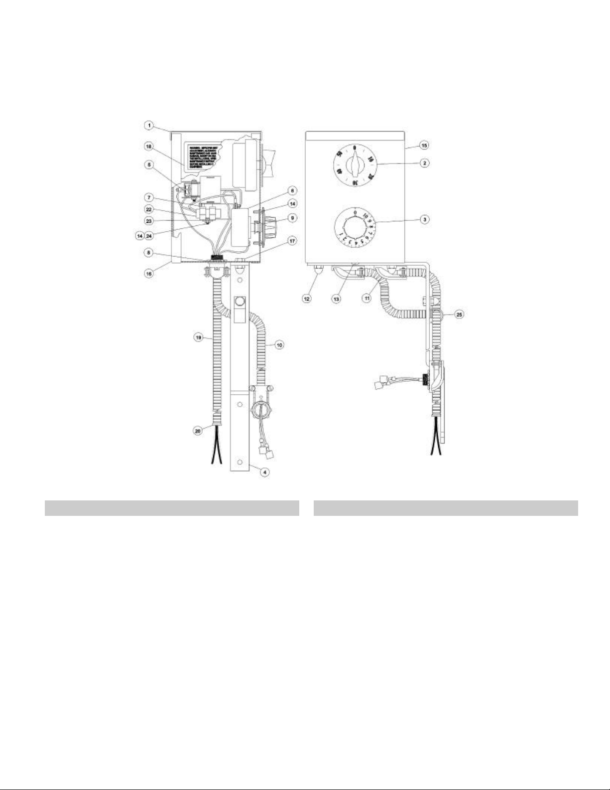
9. Parts List
Control Console Assembly
OSM-HFP/2E-CE
Key Description Part No. Key Description Part No.
1 Control Console Weldment 122174 14 Screw, Rd. Hd. #6-32 x 3/8" 009697
2 Timer 0-60 minute w/Dial & Knob 001154 15 Control Console Front Cover 000434
3 Knob, Thermostat 122000 16 Control Console Back Cover 000433
4 Bracket, Control Console Mounting 122175 17 Screw, hex hd. 1/4-20 x1/2" 005608
5 Thermostat, High Limit 119464 18 Label, Warning AGA Addenda B 099961
6 Thermostat 100º to 450º w/Dip Seal 041700 19 Conduit, Flexible 5/16 DSL-6 9" 006940
7 Hex slot washer head #6-32 x 1/4" 069777 20 Conduit, Insulator 071934
8 Nut, Hex Jam 3/8-24 003473 21 Locktite #242 non-vibration (not shown) 073282
9 Grommet 1/4" IDx1/2" ODx1/16 Groove 001518 22 Switch, Mercury 122176
10 Wire, Control Console Kit 119459 23 Mounting Bracket for 122176 122177
11 Elbow, 90º 3/8" Conduit Connect #266 004098 24 Nut, Hex 6-32 012630
12 Nut, Dome, High Profile 1/4-20 090567 25 1/2" Clamp, Rigid Conduit 068687
13 Screw, truss hd. #8 x 3/8 SS 005764
23
Page 24

OSM-HFP/2E-CE
9. Parts List
Electrical Panel Assembly - P/N 119416
Key Description Part No. Key Description Part No.
1 Chassis, Electrical 119434 8 Label, 3 Amp (Fast Blow Only) 102251
2 Pilot, Ignition Controller 220/240V 113060 9 Screw, hex washer hd. #8-32 x 3/8 069789
3 Filter, Line 3VK1 119456 10 Screw, hex slotted washer hd #6-32 x 1/4 069777
4 Fuse Holder 077854 11 Screw, Rd. hd. #8-32 x 1-1/4 005056
5 Fuse, Three Amp (250V) 079965 12 Label, Ground 003384
6 Terminal Block (3 Pole) 003888 13 Screw, Nylon #8-32 x 1/2" 127421
7 Label, Supply Voltage 114316 14 Spacer, Nylon 0.174 x 1/4 OD x 1/4 127420
24
Page 25

OSM-HFP/2E-CE
9. Parts List, Fuel Gas Conversion
(For conversion of a natural gas unit to propane, or a propane model to natural gas)
HFP/2E WITH ELECTRONIC IGNITION
DESCRIPTION QTY G20 NAT GAS G25 NAT GAS G31 LP GAS
Pilot Orifice 1 119449 119449 098647
Main Burner Orifice Size 3 13 045897 128158 050047
Main Burner Orifice Size 4 18 045897 128157 050047
Ignition Tube Orifice Size 3 1 101622 101622 114340
Ignition Tube Orifice Size 4 1 101621 101621 101623
NOTE: Gas Valve Part Number remains P/N 114505
25
Page 26

OSM-HFP/2E-CE
10. Service Log
Model No. ___________________________ Purchased From _____________________
Serial No. ___________________________ Location ____________________________
Date Purchased ______________________ Date Installed ________________________
Purchase Order No. ___________________ For Service Call ______________________
Date Maintenance Performed Performed by
26
Page 27

OSM-HFP/2E-CE
Limited Warranty To Commercial Purchasers*
(for Areas Outside of the U.S. and Canada)
Groen Foodservice Equipment ("Groen Equipment") has been skillfully manufactured, carefully inspected and
packaged to meet rigid standards of excellence. Groen warrant their Equipment to be free from defects in
material and workmanship for (12) twelve months, with the following conditions and subject to the following
limitations.
I. This parts and labor warranty is limited to Groen Equipment sold to the original commercial purchaser/ users
(but not original equipment manufacturers), at its original place of installation, in areas outside the U.S. and
Canada.
II. Damage during shipment is to be reported to the carrier, and is not covered under this warranty, and is the sole
responsibility of the purchaser/user.
III. Groen, or an authorized service representative, will repair or replace, at Groen's sole election, any Groen
Equipment, including but not limited to, draw off valves, safety valves, gas and electric components, found to
be defective during the warranty period. As to warranty service in the territory described above, Groen will
absorb labor and portal to portal transportation costs (time & mileage) for the first twelve (12) months from
date of installation or fifteen (15) months from date of shipment from Groen.
IV. This warranty does not cover boiler maintenance, calibration, or periodic adjustments as specified in
operating instructions or manuals, and consumable parts such as scraper blades, gaskets, packing, etc., or
labor costs incurred for removal of adjacent equipment or objects to gain access to Groen Equipment. This
warranty does not cover defects caused by improper installation, abuse, careless operation, or improper
maintenance of equipment. This warranty does not cover damage caused by poor water quality or improper
boiler maintenance.
V. THIS WARRANTY IS EXCLUSIVE AND IS IN LIEU OF ALL OTHER WARRANTIES, EXPRESSED OR
IMPLIED, INCLUDING ANY IMPLIED WARRANTY OF MERCHANTABILITY OR FITNESS FOR A
PARTICULAR PURPOSE, EACH OF WHICH IS HEREBY EXPRESSLY DISCLAIMED. THE REMEDIES
DESCRIBED ABOVE ARE EXCLUSIVE AND IN NO EVENT SHALL GROEN BE LIABLE FOR SPECIAL,
CONSEQUENTIAL OR INCIDENTAL DAMAGES FOR THE BREACH OR DELAY IN PERFORMANCE OF
THIS WARRANTY.
VI. Groen Equipment is for commercial use only. If sold as a component of another (O.E.M.) manufacturer's
equipment or if used as a consumer product, such Equipment is sold AS IS and without any warranty.
* (Covers All Food Service Equipment Ordered After October 1, 1995)
27
Page 28

1055 Mendell Davis Drive
Jackson, MS 39212
Telephone 601 372-3903
FAX 601 373-9587
OSM-HFP/2E-CE
Revised 10/99
Part Number 128431
 Loading...