

Page 1
OPERATOR MANUAL
IMPORTANT INFORMATION, KEEP FOR OPERATOR
This manual provides information for:
MODELS
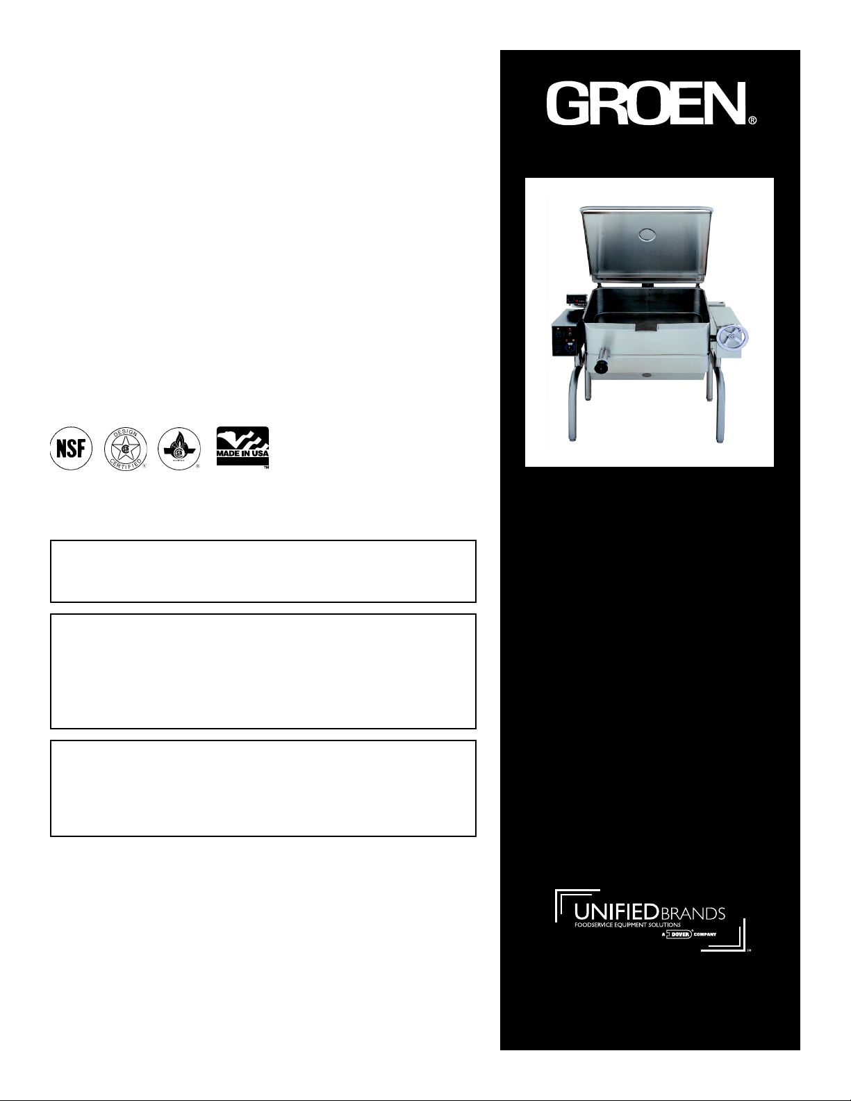
HFP/2E & HFP/2 Domestic
BRAISING PAN
·
Stainless Steel
·
Manual Tilt
·
Gas Heated
READ, UNDERSTAND AND FOLLOW THE INSTRUCTIONS AND
WARNINGS CONTAINED IN THIS MANUAL.
FOR YOUR SAFETY
Do not store or use gasoline or other flammable vapors
and liquids in the vicinity of this or any other appliance.
POST IN A PROMINENT LOCATION
Instructions to be followed in the event user smells gas.
This information shall be obtained by consulting your
local gas supplier. As a minimum, turn off the gas and
call your gas company and your authorized service agent.
Evacuate all personnel from the area.
WARNING
Improper installation, adjustment, alteration, service or
maintenance can cause property damage, injury or death.
Read the installation, operating and maintenance instructions
thoroughly before installing or servicing this equipment.
NOTIFY CARRIER OF DAMAGE AT ONCE
It is the responsibility of the consignee to inspect the container upon receipt of
same and to determine the possibility of any damage, including concealed damage. Unified Brands suggests that if you are suspicious of damage to make a
notation on the delivery receipt. It will be the responsibility of the consignee to file
a claim with the carrier. We recommend that you do so at once.
.ECNEREFER ERUTUF ROF DENIATER EB TSUM LAUNAM SIHT
Manufacture Service/Questions 888-994-7636.
Information contained in this document is known to be current and accurate at the time
of printing/creation. Unified Brands recommends referencing our product line websites,
unifiedbrands.net, for the most updated product information and specifications.
PART NUMBER 121023, REV. C (01/03)
1055 Mendell Davis Drive
Jackson, MS 39272
888-994-7636, fax 888-864-7636
groen.com
Page 2

OM-HFP
IMPORTANT — READ FIRST — IMPORTANT
CA UTION: SHIPPI NG STRA P S ARE UNDER TENSION AND CAN SNAP BACK WHEN CUT.
CA UTION: UNIT WEI GHS 370 TO 560 LB. (165 TO 255 KG). FOR SAFE HANDLING, INSTALLER
SHOULD OBTAIN HELP AS NEEDED, OR EMPLOY APPROPRIA TE MATERIALS HANDLING
EQUIPME NT (SUCH AS A FORKL IFT, DOL L Y, O R PALLET JACK) TO REMOVE THE UNIT
FROM THE SKID AND MOVE IT TO THE PLACE OF INSTALLATION.
WA RNING: INSTALLATIO N O F THE BRAISING P AN MUST BE DONE BY PE RSONNEL QUALIFIE D TO
WORK WITH GAS AND ELECTRICITY. IMPROPER INSTALLATION CAN RESULT IN INJURY
TO PERSONNEL AND/OR DAMAGE TO EQUIPMENT.
WARNING: THIS UNIT IS DESIGNED FOR COMMERCIA L USE. NEVER USE HOME OR RESIDENTIAL
GRADE GAS CONNECTIONS . THEY DO NOT MEET GAS CODES AND COULD BE
HAZARDOUS.
DA NG ER: ELECTRI CALLY GROUND THE UNIT AT THE TERMINAL P ROVIDED. FAILURE TO GROUND
UNIT COULD RESULT IN E L ECTROCUTION AND DEATH.
WARNING: KEEP THE APPLIANCE AREA FREE AND CLEAR OF COMBUSTIBLE MATERIALS.
CA UTION: BE SURE ALL OPERATORS READ, UNDERSTAND AND FOLLOW THE OPERATI NG
INSTRUCTI O NS, CAUTI ONS AND SAFETY INSTRUCTIONS CONTAINED IN THIS MANUAL.
CAUTION: KEEP FLOORS IN BRAISI NG PAN WORK AREA CLEAN AND DRY. IF SPILLS OCCUR,
CLEAN IMM EDI ATELY TO AVOID THE DANGER OF SLIPS OR FALLS.
WA RNING: WHEN TILTING BRAI SING PAN FOR PRODUCT TRANSFER:
1) USE CONTAINER DEEP ENOUGH TO CONTAIN AND MINIMIZE PRODUCT SPLASHING.
2) PLACE CONTAINER ON STABLE, FLAT SURFACE, AS CLOSE TO PAN AS POSSIBLE.
3) STAND TO SIDE OF P AN WHILE POURING — NOT DIRECTLY IN POUR PATH OF HOT
CONTENTS.
4) RETURN PAN BODY TO LEVEL POSITION AFTER CONTAINER IS FILLED OR
TRANSFER IS COMPLETE.
5) DO NOT OVE R F ILL CONTAINER. AVOID DIRECT SKIN CONTACT WITH HOT
CONTAINER AND ITS CONTENTS.
WA RNING: DO NOT HEAT EMP TY PAN FOR MORE THAN 5 MINUTES AT A SETTING HIGHER THAN
WA RNING: IF THE P AN CONTAINS ITEMS IN SAUCE OR MELTED FAT, THEY CA N SLI DE FORWARD
WA RNING: A VOID ALL DIRECT CONTACT WITH HOT FOOD OR WATER IN THE PAN. DIRECT
WARNING: KEEP WATER AND SOLUTIONS OUT OF CONTROLS AND BURNERS. NEVER SPRAY OR
CA UTION: MOST CLEANERS ARE HARM F UL TO THE SKIN, EYES, MUCOUS MEMBRANES AND
WARNING: THE CONTROL BOX IS NOT WATERPROOF. TAKE CARE TO KEEP WATER AND
WARNING: BEFORE REPLACING ANY PARTS, DISCONNECT THE UNIT FROM THE ELECTRIC POWER
CAUTION: USE OF ANY REPLACEMENT PARTS OTHER THAN THOSE SUPPLIED BY GROEN OR
IMPORTANT: Service performed by other than factory authorized personnel will void all warranties.
o
300
F.
SUDDENLY DURING TILTING AND CAUSE THE HO T LIQUID TO SPLASH OUT.
CONTACT COULD RESULT IN SEVERE BURNS.
HOSE THE CONTROL CONSOLE, OR ELECTRI CAL CONNECTIONS.
CLOTHING. PRECAUTIO NS SHOULD BE TAKEN TO WEAR RUBBER GLOVES, GOGGLES
OR FACE SHIELD AND PROTECTIVE CLOTHING. CAREFULLY READ THE WARNINGS AND
FOLLOW THE DIRECTI ONS ON THE LABEL OF THE CL EANER TO BE USED.
CLEANING SOLUTIONS OUT OF THE BOX. NEVER HOSE OR SPRAY ELECTRICAL
CONTROLS, CONNE CTIONS OR CONTROL CO NSOLE.
SUPPLY AND CLOSE THE MAIN GAS COCK. ALLO W F IVE MI NUTE S FOR UNBURNED GAS
TO VENT.
A UTHORIZED DISTRIBUTORS CAN CAUSE INJURY TO THE OPE RATOR AND DAMAGE TO
THE EQUIPMENT AND WILL VOID ALL WA RRANTIES.
2
Page 3

Table of Contents
IMPORTANT OPERATOR WARNINGS (READ FIRST) ........................................ 2
REFERENCES ......................................................................... 3
EQUIPMENT DESCRIPTION .............................................................. 4
INSPECTION AND UNPACKING ........................................................... 5
INSTALLATION ......................................................................... 6
INITIAL START-UP ...................................................................... 7
OPERATION ........................................................................... 7
SEQUENCE OF OPERATION ............................................................. 9
CLEANING............................................................................ 10
MAINTENANCE........................................................................ 12
TROUBLESHOOTING .................................................................. 12
PARTS LIST .......................................................................... 15
DIAGRAMS & SCHEMATICS............................................................. 24
MAINTENANCE LOG ................................................................... 26
WARRANTY .......................................................................... 27
References
American Gas Associati on Laborat ories
8501 East Pleasant Valley Rd.
Cleveland, Ohio 44131
Z223.1-1984 National Fuel Gas Code
American National Standards Institut e
1403 Broadway
New York, New York 10018
Canadian Gas Associat ion
55 Scarsdale Road
Don Mills, Ont a rio M3B 2 R3
ECOLAB, INC.
370 Wabasha
St. Paul, Minnesota 55102
National Fi re P rot ect ion Association
60 Battery March Park
Quincy, Mass achus etts 02269
NFPA/54 Installation of Gas Appliances &
Gas Piping
NFPA/70 The National Elect ri cal Code
NFPA/96 Ventilati ng Hoods
National Sani tation Foundation
3475 Plymouth Road
Ann Arbor, M ichigan 48106
Underwriters Laboratories, I nc.
333 Pfingst en Road
Northbrook, Illinois 60062
ZEP M anufacturing
1390 Lunt Av enue
Elk Grove Vi llage, Illinois 60007
3
Page 4
OM-HFP
Equipment Description
Groen Gas Heated Brai sing Pans provi de a
stainless steel pan equipped with pat ent ed heat
transfer fins, burner/combustion chamber, handoperated tilting mechanism, thermostatic
controls, and hinged cover. The Braising Pan
serves as brais ing unit, griddle, fry pan, ov en,
kettle, bain-marie, or food w armer and server,
and it can be adapted for use as a steamer.
The pan body is made from heavy-duty stainless
steel welded into one solid piece, with a
polished in t erior and exteri or. A pouring lip is
welded to the front wall. The cooking surface i s
a stainless steel clad plate fitted w ith welded
heat transfer fins which assure uniform heat
transfer over the entire s urface. The gas
burner/combustion chamber supplies the heat.
An easily operated worm and gear mechanism
tilts t he pan and provi des precise control for
pouring or dumping the contents of the pan. This
hand-wheel controlled mechanism is located in
a stainless steel console to the right of the pan
body. To ass ist cleaning, the pan body can be
tilted past the vert ical position. When the pan is
tilted, t he burners shut off automatically.
Model
HFP/2E-2 24
HFP/2-2 24
HFP/2E-3 31
HFP/2-3 31
HFP/2E-4 41
HFP/2-4 41
Options avai lable wi th these models are:
1. Fill faucet with swing spout. (Left or right
mounted)
2. Caster mounting kit.
3. Fold-down work tray (pan s upport ) mounted on
left or right side.
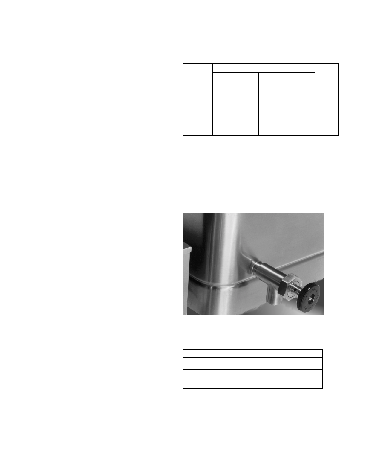
4. 2” Tangent draw-off (Factory-installed option)
5. Model REJ Steamer Insert set.
6. Steamer Pan Carrier.
7. Quick gas disconnect w ith rest raining cable.
e” (62.5cm) 9" ( 23cm) Spark
e” (62.5 cm) 9" ( 23cm) Flame
Pan Dimensions
L to R Depth
e” (80 cm) 9" ( 23cm) Spark
e” (80 cm) 9" ( 23cm) Flame
e” (1.06m) 9" ( 23cm) Spark
e” (1.06m) 9" ( 23cm) Flame
Ignition
The thermostat provides automatic control of
cooking temperature. Operati ng t he thermostat
dial on the front of the control console turns the
heat on or off and sets the pan t emperature.
A vent ed, heavy gauge, one-piece, stainless
steel cover w ith a condensate drip shield on the
rear edge is standard on the Brai sing Pan. A
fully enclosed, spring t ype actuator count erbalances the cover to keep it in either the
opened or closed position. The cover opens t o
the back and is hinged to the frame, so it moves
independently of the pan body.
Models HFP/ 2E , and HFP/2 are mounted on an
open-leg frame fabricated from tubular stainless
steel.
Model HFP/2E has an ignition s yst em that uses
electronic spark ignition. Optional model HFP/2
has a standing-flame pilot light that ignites t he
main burner.
Optional Tangent Draw-Off
Performance Data
MODEL S FIRING RATE
HFP/2-2, HFP/2E-2
HFP/2-3, HFP/2E-3
HFP/2-4, HFP/2E-4
80,000 BTU/hr
104,000 BTU/hr
144,000 BTU/hr
4
Page 5
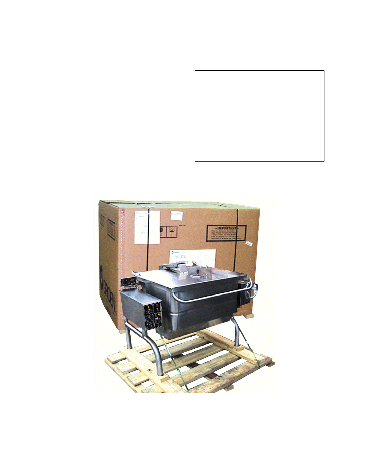
Inspection and Unpacking
The unit will arrive completely ass embled,
wrapped in protect ive plastic on a heavy s kid, in
a heavy cardboard carton. I mmediately upon
receipt, inspect the cart on for damage. Report
any apparent s hipping damage or an incorrect
shipment to the deli very agent.
When installation is to begi n, get someone to
assist in remov ing the carton. Lift it strai ght up
and away from the unit. Do not simply raise it
and push backwards - you will break the
cover assembly vent handle. Write down the
model number, serial number, and installati on
date of your unit, and keep this information for
future reference. Space for these entries i s
provi ded at the top of the Service Log in thi s
manual.
Cut the straps holding the uni t on the skid, and
lift the unit strai ght up off the skid.
CAUTION
SHIPPING STRAPS ARE UNDER TENSION
A ND CAN SNAP BACK WHEN CUT.
UNIT WEIGHS 370 TO 560 LB (170 TO 255
KG). FOR SAFE HANDLING, INSTALLER
SHOULD OBTAIN HELP AS NEEDED, OR
EMPLOY APPROPRIATE MATERIALS
HANDLING EQUIPMENT (SUCH AS A
FORKLIFT, DOLLY, OR PALLET JACK) TO
REMOVE THE UNIT FROM THE SKID AND
MOVE IT TO THE PLACE OF INSTALLATION.
The unit is strapped to a ski d , an d shipped in a heavy
cardboard carton.
5
Page 6

OM-HFP
Installation
Inst all the Braising Pan in a well v ent ilated room
for efficient performance. Remove any items
which might obs truct or restrict the flow of air for
combustion and vent ilation. Clear all
combustible material from the area directly
around the unit.
WARNING
INSTALLATION OF THE BRAISING PAN
MUST BE DONE BY PERSONNEL
QUALIFIED TO WORK WITH GAS AND
ELECTRICITY. IMPROPER INSTALLATION
CAN RESULT IN INJURY TO PERSONNEL
A ND/OR DAMAGE TO EQUIPMENT.
1. Installation on combusti ble floors i s allowed.
Ensure minimum clearance to combustible
and noncombustible construction of six
inches at t he rear, zero inches at t he sides.
2. Install the unit under a vent hood.
3. Level the unit by adjusti ng the bullet feet or
floor flanges on the legs. Be sure the tilting
mechanism has been turned all the way to
the horizontal position. Check levelness with
a spiri t level set on the bottom of the pan
body. A nchor t he rear legs securely to the
floor if floor flanges are ordered or required.
4. Complete piping to the gas servi ce w ith 3/4"
inch IPS pipe or approved equivalent.
WARNING
ELECTRI CAL LY GROUND THE UNIT A T THE
TERMINAL PROVIDED. FAILURE TO
GROUND UNIT COULD RESULT IN
ELECTROCUTI ON AND DEATH.
7. For electronic spark igni t ion, provide 115
VAC, 60 HZ, 1 phas e, 5 AMP electrical
service through the rear of the electri cal
console. Local codes and/or The National
Electrical Code should be observ ed in
accordance with ANS I/NFPA 70, latest
edition. AN ELE CTRICAL GROUND I S
REQUIRED. The electri cal schematic is
located on the inside of the service panel
and this manual. In Canada, provide
electrical service in accordance with the
Canadian Electri cal Code, CS A -C22. 1 Part
1 and/or local codes.
8. Installation must conform with local codes or
with t he American National Standard Z223,
latest edit ion, National Fuel Gas Code. The
pan should be installed in an adequat ely
ventilated room with a provis ion for
adequate air supply to the unit. The best
ventilation w ill use a vent hood and exhaust
fan. DO NOT obstruct the flue or vent duct
after inst allation. In Canada, installation
must conform to CAN/CGA B149 Installation
Codes for Gas Appliances and Equipment
and/or local codes
WARNING:
THIS UNIT IS FOR COMMERCIAL USE.
NEVER USE HOME OR RESIDENTIAL
GRADE GAS CONNECTIONS. THEY DO
NOT MEET GAS CODES AND COULD BE
HAZARDOUS.
5. For a unit on casters , complete connection
to the gas supply wi th connectors that
comply with t he standard for Connectors for
Mov eable Gas Appliances, ANS I Z21.69alatest edition. Res train movement of the unit
by att aching a cable or chain to the eyelet
(provi ded at the back of the frame) and
anchoring the cable or chain to t he wall or
floor. Make the length and location of the
cable such that the unit cannot pull on the
gas connection w hile the cable is connected
6. The gas connection must be made with a
quick disconnect devi ce compliant with
ANSI Z 21. 41b - latest edit ion.
9. Adequate space for proper service and
operation is required. DO NOT block any air
intake spacings to the combusti on chamber
or obstruct ai r flow.
10. After the pan has been connected to the gas
supply, check all gas joints for leaks. A soap
solution or other suitable leak detector
should be used. Do not use fl ame to check
for leaks
11. The appliance and its individual shutoff
valve must be protected from the gas
supply pi ping system during any pressure
testing of that system at test pressures in
excess of 1/2 PSI (3.45 kPa). The
appliance may be isolated from the gas
supply pi ping system by closi ng its individual
manual shutoff valve during any pressu re
testing of the gas supply piping s yst em.
6
Page 7

Initial Start-Up
Now that your Braising Pan has been installed, you
should test it to ensure t hat the unit is operating
correctly.
1. Remove literature and packing materials
from the interior and exterior of the unit.
2. Put enough water i nto the pan to cov e r t he
bottom to a depth of ¼ to ½ i nch. With the
pan body i n the horizontal position, note
how the wat er li es in the pan, to confirm that
the pan was leveled properly during
installation.
3. Following "To Start Pan" ins tructions for
your pan model, begin heating the water at
a thermostat setting of 235
heating should continue until the water boils.
o
F. At this setting,
A. Controls
Operator controls for the Brai sing Pans are:
1. Power ON Switch and Power ON indicato r
2. The thermostat di al, located on t he cont rol
console to the left rear of the pan body. Thi s dial
is used to turn the thermostat on or off and to
set the thermostat for pan t emperatures
between 175
3. HEATing indicator light located on the control
console, lights w hen the burners hav e ignit ed.
4. The main supply gas valve, installed on the gas
line to the uni t.
5. For HFP/2 units with standing pilot flame, the
gas control valv e is on the Combination Gas
Control, which is located under the pan on the
gas line to the burner manifold. This valve
selects settings of "OFF", "PILOT", or "ON" for
the Combination Cont rol. HF P /2 units are als o
equipped with a mechanical 0-60 minute bell
timer.
6. HFP/2E units are equipped w ith an electrical
timer having timing and “Done” indicator lights
and a beeper.
o
and 425o F.
4. To shut down the unit, turn the thermostat
dial to "OFF".
WARNING
WATER IS EXTREMELY HOT AND CAN CAUSE
SEVERE BURNS. AVOID CONTACT WITH HOT
WA TER WHEN EM P TYING UNI T.
5. Turn the tilting handwheel clockwis e to pour
out the water and to confirm that the pan
body can be tilted smoothly from horizontal
to vertical.
If the uni t functions as described abov e, it is ready
for use. If it does not, contact y our local Groen
Authorized S ervi ce Agency.
Operation
B. Operating Procedure
WARNING
KEEP THE APPLI A NCE AREA FREE A ND CLEAR
OF COMBUSTIBLE MATERIALS.
CAUTION
BE SURE ALL OPERATORS READ,
UNDERSTA ND AND FOLLOW THE OPE RATING
INSTRUCTIONS, CAUTIONS AND SAFETY
INSTRUCTIONS CONTAINED IN THIS MANUAL.
KEEP FLOOR S IN B R AISING PAN WORK AREA
CLEAN AND DRY. IF SPILLS OCCUR, CLEAN
IMMEDIATELY TO AVOID THE DANGER OF
SLIPS OR FALLS.
1. For Standard Models with Electronic
Ignition (HFP/2E)
a. To Start Pan (See Panel Overlay)
(1) Set the Power Switch to “OFF.”
(2) S et the thermostat to “OFF . ”
(3) Open the main supply gas valve (handle
parallel to the gas pipe).
(4) S et Power Swi tch to “ON.”
(5) Rotate the thermostat dial until the Heat
Light comes on. (I t lights w hen the main
burner is on).
7
Page 8

OM-HFP
b. To Turn Of f Pan
(1) Set the thermostat t o "OFF ".
(2) S et Power S wit ch to “OFF.”
(3) For a prolonged shut-off period:
(a) Set the thermostat t o "OFF ".
(b) Turn the main gas valve OFF
(handle at right angles to t he gas
pipe).
(c) Disconnect the electrical power from
the unit.
c. If Power Fails
1) Do not try to operate t he unit until power
is res t ored.
2) When power is restored, follow
directi ons under “To Start Pan. ”
2. For Models with Optional Standing-Flame
Pilot (HFP/2)
a. To Start Pan
(1) Set thermostat to "OFF ".
(2) Light gas pilot.
(a) Set knob on Combination Gas
Control Valve to "OFF" by
depressing the knob slightly and
turning it clockwise.
(b) Turn the main supply gas valve ON
(parallel to the gas pipe).
(c) Tilt the pan, so the pilot burner i s
easier to reach.
(d) Hold a lighted match at the pilot
burner, whi le you depress the knob
on the Combination Cont rol and turn
it counter-clockwi se to the "PILOT"
position. Continue to hold the knob
down for 60 seconds.
(e) Release the knob. The pilot flame
should stay lighted.
CAUTION
DO NOT HEAT AN EMPTY PAN FOR MORE
THAN FIVE MINUTES AT A SETTING HIGHER
THAN 300
b. To Shut Off Pan
c. To Relight P ilot
WHEN TILTING BRAISING PAN FOR PRODUCT
TRANSFER:
1) USE CONTAINERS DEEP ENOUGH TO
2) PLACE CONTAINER ON A STABLE, FLAT
3) STAND TO THE SIDE OF THE PAN WHILE
4) RETURN PAN BODY TO UPRIGHT P OSITION
5) DO NOT OVERFILL CONTAINER. AVOID
3. To Tilt Pan Body
Turn the tilti ng handwheel clockwise to tilt the
pan body, or counterclockwise to return t he pan
body to horizontal. 23 complete turns of the
hand-wheel will ti lt t he body 90 degrees t o
vertical.
o
F.
(1) Set the thermostat dial to "OFF".
(2) To turn off the gas pilot, depress the
knob on the Combination Control and
turn it clockwise to "OFF".
(1) Close the main supply gas valve.
(2) Set the thermostat t o "OFF ".
(3) Depress the knob on the Combination
Control and turn it clockwise to "OFF".
(4) Wait 5 minutes, then proceed as
instruct ed at "To Start Pan" above.
WARNING
CONTAIN AND MINIMIZE PRODUCT
SPLASHING.
SURFACE, AS CLOSE TO THE BRAISING
PAN AS POSSIBLE.
POURING — NOT DIRECTLY IN THE POUR
PATH OF HOT CONTENTS.
AFTER CONTAINER IS FILLED OR
TRANSFER IS COMPLETE.
DIRECT SKIN CONTACT WITH HOT
CONTAINER AND CONTENTS.
(f) Turn the knob counterclockwise to
"ON".
(3) Turn the thermostat dial to the des ired
temperature.
4. To Move a Unit on Casters
The unit must be anchored with a cable or chain
to avoid accidentally breaking or pulling loose
the gas connection. When the unit is to be
8
Page 9
moved, first t u rn off and di sconnect the gas
connection.
Disconnect the cable from its anchor point on
the floor or wall. Anchor the unit agai n as soon
as it is in its new operating location or returned
to the prev ious location. Turn on the gas supply
and check for leaks with a soap solution. If
leaks are found, do not operate the equi pment.
Call for service.
5. To Preheat the Pan
a. For best braising or frying results, preheat
pan before you put in any food.
b. To get an even temperature across the pan,
preheat at a sett ing of 300
o
F or less for 15
minutes or through several on-off cycles of
the burner.
CAUTION
DO NOT HEAT AN EMPTY PAN FOR MORE
THAN FIVE MINUTES AT A SETTING
HIGHER THAN 300
o
F. DAMAGE TO THE
PAN COULD RES ULT.
Cooking
C.
the product. Set the thermostat higher to cook or
driv e off moist ure fas ter. You may adjus t the
thermostat to any setting to cook the it em
exact ly as requi red.
2. Leave the cover vent open to let excess steam
escape. For long simmering operati ons , you
may wish to close the vent to retain moisture.
WARNING
STEA M CAN CAUS E BURNS . AVOID ESCAPI NG
STEAM WHEN RAISING COVER.
3. To check progress when the cover i s closed, lift
the handle of the vent cover slight ly, and move i t
quickly to either side.
4. Standing to one side of the pan (to avoid the
steam that wi ll be released) grasp the nearer
corner of the cover handle and rais e t he cover.
The cover wi ll stay in the open posit ion unti l you
push it down.
1. To simmer or slowly heat an item, set the dial at
o
210
F or lower. Put t he cover down t o minimize
moisture loss, or leave it up to help dry or
reduce
ITEMS IN SAUCE OR MELT ED FAT CAN SLIDE
FORWARD SUDDENLY DURING TILTING AND
SPLASH THE HOT LIQUID.
WARNING
5. To pour or dump product, remove grease, or
assi s t cleaning, first rais e the cover, then tilt t he
pan forward by t urning the tilting handwheel.
When you stop turning the wheel, t he pan body
will hold its position.
Sequence of Operation
The following "action-reaction" out line is provided to help the user understand how the equipment functions.
A. Standard Models with Spark Ignition
1. When the power switch is turned on, it st arts the
spark igni ter and opens the automati c valve for the
pilot burner. The spark i gnites a pilot flame, which
heats the sensor. The sensor then s ends a signal
to turn off the spark. The flame thereafter acts as a
standing pilot unti l the power is t u rned off.
2. If the pilot flame is not sens ed within 90 seconds
after spark begins, a timer shuts down the enti re
operation. To att empt a second trial for ignition,
turn off the power sw itch. Check the gas supply
valves and wait fiv e minut es before trying again by
swi t ching power on. If there is sti ll no pilot flame in
four tries, close all v alves, turn off the power, and
contact an authorized Groen S ervice A gency.
3. When the operator sets a temperature on the
thermostat, it causes the aut omatic valve t o
admit gas to the main burner, where it is i gnited
by the pilot flame. When the braising pan
reaches the set t emperature, t he t hermostat
swi t ch opens . This st ops the si gnal to t he gas
control valve and s huts off gas to the main
burner. The pilot flame remains lit . When the
pan cools below the set temperature, the
thermostat switch closes and st arts another
cycle. On and off cycling continues and
maintains t he pan at the desired t emperature.
This acti on is i ndicated by the Heat i ndicator light.
B. Models with Optional Standing Pilot Ignition
9
Page 10

OM-HFP
1. When the operator presses down the knob on t he
Combination Gas Cont rol Valve and turns it to
“Pilot”, gas is admit t ed to the pilot burner.
Depressi ng t he knob in thi s posit ion ov errides the
automatic control, whi ch ot herwise shuts off all gas
supply when t he thermopile is cold. Light ing and
maintaini ng the pilot flame for sixty seconds heats
the thermopile to operati ng t emperature, s o the
thermopile begins to provide electric current at 750
millivolts. Electricit y from the thermopile powers the
control circuit and t he Combinat ion Gas Control
Valve. When the thermopile begins operating at full
capacity , the knob may be released.
2. When the knob is turned to “ON”, the aut omati c
valv e for the main burner is able to open. S et ting
the thermostat to call for heat causes the
thermostat to send a s ignal to the valve, w hich
opens and admits gas t o the main burner. Gas from
the main burner is ignited by the pilot flame. When
the pan reaches the set temperature, the
thermostat switch opens, stopping t he signal to the
main burner valve an caus ing the valve to close.
When the pan cools below the set temperature, the
thermostat switch closes and st arts another heating
cycle. On-off cycling continues and maintai ns the
pan at the desired temperature.
C. All Models
1. The thermostat controls heating by alternat ely
calling for flames at the full capacity of t he main
burners and then signaling the control to shut the
burner off completely. Becaus e the control works
in this “all or nothing” way, the pan heats as fast
as it can unt il it reaches the set temperature, not
matter what that t emperature i s. Turning the
thermostat dial to a higher temperature will cause
heating to cont inue longer, until the pan reaches
the higher temperature, but it cannot make the
pan heat any faster.
2. The pans are protected from overheating by a
secondary t hermostat. If the pan t emperature
rises above 425º F, t he thermostat causes the
automatic gas control valve to close. When the
pan cools, the thermostat automatically resets
and permits normal operation to conti nue.
3. The tilt swi t ch w ill shut off all burners whenever
the braising pan is tilted.
4. A gas pressure regulator, w hich controls gas
pressure at the burner manifold is built into the
gas control valv e.
5. Turning the tilting handwheel turns a w orm gear,
which turns a gear wheel on one of the trunnions
which support the pan body. Turni ng the gear
wheel produces the ti lting action.
NOTE: Neither model will heat (operate) when the
braising pan has been ti lted 10 degrees or
more from the horizontal.
Cleaning
WARNING
KEEP WATER AND SOLUTIONS OUT OF CONT ROLS AND BURNERS. NEVER SPRAY OR HOSE THE
CONTROL CONSOLE O R ANY ELECTRICAL CONNECTIONS.
1. Before any cleaning operati on, shut off the
burner by turning the thermostat dial to "OFF". If
water or cleaning solution will be sprayed, unplug
the unit from the electric power s ource, or shut off
the power at the circuit breaker or fuse panel.
2. Clean all food-contact surfaces soon after use,
before the pan has cooled completely. If the unit is
in conti nuous use, thoroughly clean and sanitize
both interior and exteri or at least once every 12
hours.
10
Page 11

CAUTION
MOST CLEANERS ARE HARMFUL TO THE
SKIN, EYES, MUCOUS MEMBRANES AND
CLOTHING. PRECAUTIONS SHOULD BE
TAKEN TO WEAR RUBBER GLOVES,
GOGGLES OR FACE SHIELD AND
PROTECTIVE CLOTHING. CAREFULLY READ
THE WARNINGS AND FOLLOW THE
DIRECTIONS ON THE LABEL OF THE
CLEANER TO BE USED.
3. Scrape or rinse out large amounts of food
residues, then wash the inside of the pan body with
a mixt ure of hot water and soap or an appropriate
detergent, such as Mikro-Quat from ECOLAB.
Follow the detergent suppli er's recommendations on
strength of the s olution to use. Rinse the pan
thoroughly with hot w ater and drain completely.
4. To remove materials st uck to t he equipment,
use a brush, sponge, cloth, plasti c or rubber s craper,
or plastic wool along with the detergent or soap
solution. To mini mize the effort required in washing,
let the detergent solution si t in the pan and soak into
the residue, or heat the detergent solution bri efly in
the pan. Do NOT use any abrasive materials or
metal implement that might scratch the surface,
because scratches make the pan hard to clean and
provi de places for bacteria to grow. Do NOT use
steel wool, which may leave particles imbedded in
the pan surface and cause ev ent ual corrosion and
pitting.
5. As part of the daily cleaning program, clean all
external and internal surfaces that may have been
soiled. Remember to check such parts as the
underside of the cover, control console, etc.
6. Controls and the control console may be
cleaned with a damp cloth.
7. The exteri or s urface of the unit may be polis hed
with a recognized stainless steel cleaner, such as
"Zepper" from Zep Manufacturing Co.
Use a brush, cloth, sponge or other non-abrasive
tool for cleaning.
8. If the equipment needs to be s aniti zed, use a
sanitizing s olution equivalent to one that supplies
200 parts per million available chlorine. Obtai n
advi ce on t he best sani tizing agent from your
supplier of sani tizi ng products. Following t he
supplier's instructions, apply the sanit izing agent
after the unit has been cleaned and drained. Ri nse
off the sanitizer thoroughly.
NOTICE
NEVER LEAVE A CHLORINE SANITIZER IN
CONTACT WITH STAI NLESS STEEL SURFACES
LONGER THAN 30 MINUTES. LONGER
CONTACT CAN CAUSE CORRO SION.
9. If there is difficulty remov ing mineral deposits or
a film left by hard water or food resi dues, clean the
pan thoroughly and then us e a deli ming agent , such
as Groen De-limer/De-Scaler (P/N 114800) or LimeAway from ECOLAB, in accordance wit h t he
manufacturer's directions. Rinse and drain the uni t
before further use.
10. If especially diffi cult cleaning problems persi st,
contact your cleaning product representati ve for
assistance.
Don’t use metal implem ents o r steel wool to
clean the braisi ng p an.
11
Page 12
OM-HFP
Maintenance
Your Braising P an is designed to require
minimum maintenance, but certain parts
may need replacement after prolonged
use. After installation, no user
adjustment should be necessary. If a
service need arises, only aut horized
personnel should perform the work.
WARNING
ELECTRIC POWER ALWAYS SHOULD BE
SHUT OFF BEFORE WORK IS DONE ON
INTERNAL COMPONENTS.
Service personnel should check the unit at least
once a year. This periodi c maintenance should
include inspecting electrical wi res and connections,
cleaning the ins ide of the control console, and
possible adjustment of the pi lot li ght. At least t wice
a year, greas e the two trunnion bearings .
WARNING
DISCONNECT ELECTRICAL POWER FROM
THE UN IT BEFORE ATTEMPTING TO GRE ASE
THE TRUNNION BEARINGS.
A Serv ice Log is provided with the warranty
information at the back of this manual. Each time
service is performed on your Groen equipment,
enter the date on which the work w as done, what
was done, and w ho did it . Keep the manual with the
equipment for quick and easy reference.
Troubleshooting
Your Groen Braising P an will operate smoothly and efficiently if properly maintained. However, the following is a
list of checks to make in the event of a problem. If the actions suggested do not solve the problem, call your
qualified Groen Service Repres ent ative. For the phone number of the nearest agency, call your area Groen
representative or t he Groen P arts and Service Department. If an item on the list is followed by
only be performed by a qualified s ervi ce repres entative.
<, the work should
WARNING
BEFORE REPLACING A NY PARTS, DISCONNECT THE UNIT FROM THE ELECTRICAL POWER SUPPLY AND
CLOSE THE MAIN GAS VALVE. A LLOW FIVE MINUTES FOR GAS TO VENT.
USE OF ANY REPLACEMENT PARTS OTHER THAN THOSE SUPPLIED BY GROEN OR THEIR AUTHORIZED
DISTRIBUTORS CAN CAUSE INJURY TO THE OPERATOR AND DAMAGE TO THE EQUIPMENT AND WILL
VOID ALL WARRANTIES.
Important: Service performed by other than factory authorized personnel will void all warranties.
SYMPTOM WHO
X indicates items which must be performed by an a uthorized technician.
WHAT TO CHECK
A. All Models
Pan is hard to tilt. Auth Service
Rep Only
Burners will not light User a. That the main gas supply valve is open (handle is in line with the
Auth Service
Rep Only
Pan continues t o heat after
it reaches des ired
temperature
User a. Thermostat dial setting
Auth Service
Rep Only
a. Gears for foreign materials, lubri cat ion, and alignment. X
b. Broken tilt or w orm gears. X
gas pipe)
b. Gas supply to the building.
c. That the pan body is hori zont al.
d. Thermostat operation. The thermostat should click when the dial is
rotated to set tings above and below the t emperature of the pan. X
b. Thermostat calibration. X
c. Thermostat operation. The thermostat should click when the dial i s
rotated to set tings above and below the t emperature of the pan. X
12
Page 13

Important: Service performed by other than factory authorized personnel will void all warranties.
SYMPTOM WHO
Pan stops heat ing before
reaching desi red
temperature.
X indicates items which must be performed by an a uthorized technician.
User a. Thermostat dial setting.
Auth Service
Rep Only
b. Thermostat calibration. X
c. Thermostat operation. The thermostat should click when the dial i s
WHAT TO CHECK
rotated to set tings above and below the t emperature of the pan. X
Pan heats unevenly User a. That the pan body is horizont al.
b. That the pan is preheat ed properly in accordance with the
instruct ions i n the Operation s ect ion of this manual.
B. Standard Models with Electronic Ignition System (Refer to Schematic)
Sys tem does not produce a
spark
Spark is pres ent but the pi lot
will not light.
Pilot light s, but main burner
will not come on and spark
does not stay on.
Pilot light s, but main burner
will not come on, the spark
stays on.
Main burner comes on but
will not stay on.
Auth Service
Rep Only
Auth Service
Rep Only
Auth Service
Rep Only
Auth Service
Rep Only
Auth Service
Rep Only
a. Thermostat, and close the contacts if they are open X
b. AC voltage between terminals on s econdary side of transformer.
If it is not 24 Volt, replace the transformer X
c. That the high tension cable is in good condition. If cracked or
brittle, replace. X
d. Pilot electric ceramic for crack or break. X
e. Pilot spark gap. Regap. X
a. That the pilot valv e is securely connected to terminals. X
b. For 24 VAC at terminals PV and PV / MV. If 24V i s not present,
replace the ignit ion control module. X
b. That gas pressure is at leas t 3.5" W.C.(8.7818
b). X
c. For gas at the pilot. If it is not flowi ng:
(1) Check the pi lot gas line for kinks and obst ructions. X
(2) Clean orifice, if necess ary. X
(3) Check magnetic operator for pilot valve on gas valve.
Repair or replace as necessary. X
d. That the pilot spark gap is located in the pilot gas stream. If not,
adjust or replace the pilot burner. X
e. For drafts. Shield the pilot burner, i f necessary. X
a. Check operating thermostat to see that it is closed at temperature
setting higher than t hat of the current pan temperature. X
b. For 24 V between terminals MV and P V/MV . If 24V is not
present, replace the i gniti on cont rol module. X
c. That gas pressure is at least 3.5" W.C.(8.7818
b). X
d. Electrical connections of the main valve to terminals, t o assure
that they are securely at t ached. Check magnetic operat or for
main valve on gas valve. Repair or replace as neces s a ry. X
e. That secondary thermostat sw itch is closed.X
a. Check for bad burner ground. If necessary, repair with high
temperature wire. X
b. Pilot burner ceramic insulator for cracks. X
c. That high tens ion cable is not grounded out. If it is, correct the
ground-out condition or the pilot burner. X
d. For proper gas pressure. X
e. Clean pilot assembly, or replace if necessary. X
f. Tighten all mechanical and electrical connections. X
g. If the pilot flame is weak, i ncreas e pilot orifi ce s ize. X
h. Replace ignition control module. X
a. Check burner ground for bad wire or connection. Replace if
necessary with high temperature wi re. X
b. Check for low gas supply pressure. If necessary, replace igni tion
control module. X
13
Page 14

OM-HFP
Important: Service performed by other than factory authorized personnel will void all warranties.
SYMPTOM WHO
X indicates items which must be performed by an a uthorized technician.
C. Models with Standing Pilot Ignition System
Pilot will not light. User a. Lighting procedure, to ensure that the instructions i n t he
Operation sect ion of this manual are followed
Pilot flame goes out when
Combination Control knob is
released.
Pan will not heat, and pilot
light is out
Pan will not heat, but pilot
light is burning
Auth Service
Rep Only
Auth Service
Rep Only
User a. Is the Combination Gas Control Valv e knob t urned ON?
Auth Service
Rep Only
Auth Service
Rep Only
b. That the pilot gas supply li ne is purged of ai r. X
c. Pilot gas adjustment screw, to ensure t hat it is open. X
d. Pilot tubing and orifice for clogging. X
a. Pilot gas adjustment. X
b. Are connections from Powerpile generator to Pilotstat power unit
and Powerpile operator clean and secure? X
c. Are open and closed circuit output voltages of the generator in
the acceptable range shown by the charts in the manual for the
W720 Systems Tester? X
d. Resistance of the Pilotstat power unit. X
e. If an appropriate meter is not available, replace the generator
first, t hen the power unit. X
b. Check the pilot tubing and ori fice for clogging.
c. Are connections from Powerpile generator to Pi lots tat power unit
and Powerpile operator clean and secure?X
d. Are Open and closed circuit output voltages of the generator in
the acceptable range shown by the charts in the manual for the
W720 Systems Tester?X
e. If an appropriate meter is not available, replace the generator. X
a. That secondary thermostat sw itch is closed.
WHAT TO CHECK
14
Page 15

Parts List - HFP/2E & HFP/ 2
(Keyed t o Drawing on Page 16)
To order parts, contact your authorized Groen S ervi ce Agency. Supply the model designati on, part description, part
number, quantity , and, where applicable, voltage and phase.
Key Description Part No. Key Description Part No.
1 Gear Carrier Assembly (Cast ing) 014079 29 Vent Cov er with Stud 003265
2 Worm Gear Sector 009829 30 Spacer - Short 002378
3 Thrust Bearing 002790 31 Knob - Plasti c 002408
4 Worm Gear (Single R.H.) 012026 32 Arm - Vent Cover 002377
5 Handwheel Shaft (15
6 Handwheel Ass embly 012061 34 Spacer - Long 012733
7 Handwheel Shaft & Worm Assy. 049868 35 Gas Control Valve - Nat. Stnd. P lt. 002648
8 Bushing - Snap 000453 36 Gas Control Valve - Prop. Stnd. Plt 002649
9 90º Alemite Grease Fitting 012195 37 Pilot Burner (Nat ural) St nd. Plt. 001125
10 Hex Head Screw
11 Washer - Lock
12 Retaining Ring - external (2") 012826 40 Timer, Mech, Standi ng Pilot 001154
13 Alemite Grease Fit ting (st raight) 012100 41 Tilt Swi tch & Clip 122176
14 Nut - Hex
15 Swivel Joint 076680 43 Thermostat (100ºF to 450ºF) 041700
16 Trunnion Race (Casti ng) 013488 45 Transformer 120/24V 106233
17 Hex Head Screw
18 Orifice #54 (Natural Gas) 045897 46b Pilot Bracket, Standing P ilot 128518
19 Orifice #65 (Propane Gas) 050047 47 Pilot Burner - Elec. I gnition 127578
20 Gas Valve Manual Shut-Off 098458 50 Burner Tube 051619
21 Actuator Bracket Assy (size 2) 9" 074630 51 Gas Valve Natural - Elec. Igni tion 123815
22 Actuator Bracket Assy (s ize 3-4) 014085 52 Gas Valve Propane - Elec. Ignition 128412
23 Spring (size 2) 012413 53 Orifice Ignition Tube
24 Spring (size 3 & 4) 012533 54 Igni t ion Tube Size 2 128810
25 Spring Rod As sembly 012524 Igni t ion Tube Size 3 128809
26 Cover As sembly (size 2) 014030 I gniti on Tube Size 4 128808
27 Cover As sembly (size 3) 048798
28 Cover As sembly (size 4) 046450
d -16 003566 42 Thermostat (425ºF) 013481
d” long) 003123 33 Nut - Acorn 005471
d” -16 x 1" long 005612 38 Pilot Burner (Propane) Stnd. Plt. 001129
d” 005618 39 Thermopile - Standing Pilot 001126
d” - 16 x 1½ ” lg. 005615 46a Pilot Bracket - Electronic Ignition 119418
See Table
15
Page 16

OM-HFP
Parts List - HFP/2E & HFP/ 2
16
Page 17

Parts List
Pan Sub-Assembly, HFP/2E
Key Descrip tion Part No. Key Description Part No.
1 Pan Sub-Assembly HFP/2-4 127652 6 Tee, ½" NPT 008772
Pan Sub-Assembly HFP/2-3 127582 7 Nipple, ½" NPT x 12" Long (Size 4) 005600
Pan Sub-Assembly HFP/2-2 127763 Nipple, ½" NPT x 12" Long (Si ze 2) 008227
2 Valve, Gas 123815 8 Elbow, 90º Union, ½" NPT 141354
3 Assy Comb Chamber-burner HFP/2E-4 127666 10 Connector Male, ½” NPT x ¼” tube 049429
Assy Comb Chamber-burner HFP/2E-3 127665 11 Clamp, Conduit, 3/8" 008224
Assy Comb Chamber-burner HFP/2E-2 127664 12 Clamp, 1/4" Duplex Tube 005045
4 Elbow 1/8" NPT x ¼" tube (90º) 097195 13 Nut, Hex #10 x 32 013613
17
Page 18

OM-HFP
Parts List
Combustion Chamber & Burner Assembly, HFP/2E-4
Key Descrip tion Part No. Key Description Part No.
1 Combustion Chamber assy, HF P/2E-4 119409 12 Ignition Tube As sy, s ize 4, (natural gas) 127621
2 Burner Tube 051619 13 Screw, #10-32 x 1" hex, slott ed head cap 093478
3 Mani fold Assembly complete HFP/2E-4 069709 14 Nut, hex keps #10-32 071256
4 Sheet metal screw #10, 3/8" long 074507 15 Lock Washer #10, stainless steel 005654
5 Screw #10-32 x ¼” fill. hd, slotted 090797 16 Hex nut with i ntegral washer 012940
6 Bracket, Pi lot 119418 17 Screw, round head ¼” x 20 x 1" 012847
8 Pilot Orifice Spud, . 026" 119449 18 Bracket, Cable routing 119468
9 Assembly, Pilot Burner 127578 19 Clamp, Conduit 3/8" 008224
10 Clamp, Igniter Tube 085107
18
Page 19

Parts List
Combustion Chamber & Burner Assembly, HFP/2E-3, -2
Key Descrip tion Part No. Key Description Part No.
1 Combustion Chamber assy, HF P/2E-3 119426 12 Ignition Tube As sy, s ize 3, (natural gas) 127620
2 Burner Tube 051619 13 Screw, #10-32 x 1" hex, slott ed head cap 093478
3 Mani fold Assembly complete HFP/2E-3 069255 14 Nut, hex keps #10-32 071256
4 Sheet metal screw #10, 3/8" long 074507 15 Lock Washer #10, stainless steel 005654
5 Screw #10-32 x ¼” fill. hd, slotted 090797 16 Hex nut with i ntegral washer 012940
6 Bracket, Pi lot 119418 17 Screw, round head ¼” x 20 x 1" 012847
8 Pilot Orifice Spud, . 026" 119449 18 Bracket, Cable routing, HFP/ 2-3, -2 123726
9 Assembly, Pilot Burner 127578 19 Clamp, Conduit 3/8" 008224
10 Clamp, Igniter Tube 085107
19
Page 20

OM-HFP
Parts List
Control Console Assembly, HFP/2E
(HFP/2E shown; HFP/2 is similar)
Key Descrip tion Part No. Key Description Part No.
1 Control Console Shell Assembly 127546 12 Screw, hex head cap #10-32 x 3/8" 128757
3 Knob, thermostat 128525 13 Screw, rd. hd, machine #6-32 x 3/8" 009697
4 Bracket, Control Console mounting 122175 15 Conduit, flexible 5/16 006940
5 Thermostat 425ºF 013481 16 Conduit, insulator 071934
6 Thermostat 100º to 450º wit h dip seal 041700 18a S witch, Mercury, E lec. Ignit ion 128820
7 Conduit Nut, ½ ” 005487 18b Switch, M ercury, St anding Pi lot 122176
8 Grommet, ¼ I D x ½ OD x 1/16 groove 001518 19 Mercury Sw itch M ounting Bracket 122177
9a Harness, wiring, thermostat box 127695 20 Clamp, conduit, rigid 3/8" 008224
9b Harness, wiring t-stat box Stdg. Plt. 128650 21 Nut, dome, high profile #10-32 128756
10 Elbow 90º 3/8" conduit connector #266 004098 22 Ov erlay, Control Console 127688
11 Nut, dome, high profi le ¼ - 20 090567
20
Page 21

Parts List
Ignition Control Cabinet Assembly, HFP/2E
Key Description P art No . Key Description Part No.
1 Cover, Ignit ion Control Cabinet 119441 Label, “208 Volts” 008118D
2 Side panel, Ignition Control Cabinet 119440 Label, “240 Volts” 008118G
3 Weldment, Ignition Control Cabinet 127508 13 Knob, Timer 123100
4 Screw, pan head 8-32 x 3/8" 005764 14 Electrical Timer 24 VAC 60 Hz 096826
5 Indicator Light, amber, 24 VAAC 116384 15 Wi ring Diagram (not show n) 127748
6 Indi cat or Light, red, 24 VAC 116383 16 Timer Nut 101145
7 On/Off Toggle Switch w/ . 25" t erminals 006904 17 Beeper 128355
8 Overlay HF P front panel 123829 18 Harness Wiring Kit (not shown) HFP / 2E 128286
9 electrical components assembly 127510 Harness Wiri ng Gas Valve Sect . HFP/2E 128287
10 Label, Warning “High V oltage” 072140 Grounding Wire HFP/ 2E Pilot B urner 128288
11 Label, “Single Phase” 008118K Harness, Wiring T-stat Box HFP/2E 127695
12 Label, “115 Volts” 008118B Harness, Wiring, Main HFP/2E 127743
21
Page 22

OM-HFP
Parts List
Electrical Panel Assembly Assembly, HFP/2E
Key Descrip tion Part No. Key Description Part No.
1 Spark Ignition Module 085153 8 Lug, Ground 14-6 AWG 119829
2 Transformer 20VA, 120V, 24V Second 137487 9 Screw, round head, 8-32 x 1¼ ” long 005056
3 Screw, pan head 8-32 x 3/8" long 005764 10 Label, “Earth Ground” 003384
4 Terminal Block, 2 Pole #4 #18 AWG 003887 11 Label Electrical Connection or 102229
5 Label “3 Amp Fast Blow Only” 102251 Label Supply Voltage (li ne-neut ral-grnd) 114316
6 Fuse Holder 077854 12 Fuse, 3. 0 A mp, Type 3 AG 077853
7 Screw round head, 6-32 x ¼” long 018384 13 Electrical panel 127509
14 Nut, hex keps #10-32 with shake-proof
washer
071256
22
Page 23

Parts List - Fuel Gas Conversion
(For conversion of a natural gas unit to propane or a propane model to natual gas)
Model: HFP/2E and HFP/2
HFP/2E WITH ELECTRONIC IGNITION HFP/2 WIT H STANDING PILOT
DESCRIPTION QTY NAT GAS LP GA S DESCRIPTIO N QTY NAT GAS L P GAS
Pilot Ori fice 1 119449 098647 Pilot Burner 1 001125 001129
Burner Orifice
Igni t ion Tube Orifice S ize
4
Igni t ion Tube Orifice S ize
3
Igni t ion Tube Orifice S ize
2
Gas Valve 1 123815 128412 Gas Valve 1 002648 002649
Serial Plate 1 104961 104961 Serial Plate 1 104961 104961
% 045897 050047 Burner Orifice % 045897 050047
1
101621 112603
1
101622 114340
1
056932 101625
Igni t ion Tube Orifice S ize
4
Igni t ion Tube Orifice S ize
3
Igni t ion Tube Orifice S ize
2
1
1
1
101621 112603
101622 114340
056932 101625
*Burner Orifice “Quantity” Chart
Model Size 2 Size 3 Size 4
HFP/2101318
23
Page 24

OM-HFP
Diagrams and Schematics
Electronic Ignition System
24
Page 25

Diagrams and Schematics
Standing Pilot Ignition System
25
Page 26

OM-HFP
Service Log
Model No. ______________________________ Purchased From _________________________
Serial No. ______________________________ Location _______________________________
Date Purchased _________________________ Date Installed ___________________________
Purchase Order No. ______________________ For Service Call _________________________
Date Maintenance P erfo rmed Performed by
26
Page 27

LIMITED WARRANTY TO
COMMERCIAL PURCHASERS*
(U.S. & Canadian Sales Only.)
Groen warrants t o original commercial purchaser/users that foods ervice equipment manufactured by Groen
(“Groen Equipment”) (other than CapK old foods ervice equipment) shall be free from defects in materi al and
workmanship for (12) twelv e months from the date of installation or fifteen (15) months from date of shipment
from Groen, whichever dat e first occurs (t he “Warranty Period”), i n accordance with the following terms and
conditions:
I. This warr anty is limited to replacement parts and related labor for Groen Equipment located at its
original place of installation in t he United St at es and Canada.
II. Damage to Groen Equi pment t hat occurs duri ng s hi pment must be reported to the carri er, and i s not
covered under thi s w arrant y . The reporti ng of any damage during shipment is the s ole responsi bi li ty
of the commercial purchaser/user of such Groen Equipment.
III. For Groen Convecti on Combo
TM
Steamer-Ovens, HyPerSt eamTM Convecti on Steamers and HyPlus
Pressureless S teamers, Groen further warrants to the original commercial purchaser/users of such
Groen Equipment that the atmospheric steam generators or boilers contained in such Groen
Equipment shall be free from defects in material and workmanship for tw enty-four (24) months from
the date of installation or twenty-seven (27) months from date of shipment from Groen, whichever
date first occurs, provided that: (a) the original purchaser/user shall have also purchased and
installed a Groen PureSteem Water Treatm ent System
Convecti on Combo
TM
Steamer-Oven, Hy PerSteamTM Convect ion Steamer or HyPlusTM Pressureless
TM
for use in connection with such Groen
Steamer on or before the dat e such Groen Equipment was installed, (b) the original purchaser/ us e r
has conti nuously used suchWater Treatment System in connecti on wi th such Groen Equipment from
the date of installation, and (c) the commercial p ur c ha se r/user shall have maintained such Water
Treatment System in accordance with the maintenance and filter cartridge replacement
recomm enda tion s of Groen, and otherwise maintained such Oven or Steamer in accordance with
all other operational and maintenance recommendations of Groen.
IV. Groen further warrants to the original comm ercial purchaser/users of Groen Convection Com bo
Steamer-Ovens that the electronic relay and control board conta ined in such Groen Convection
Combo
TM
Steamer-Oven shall be free from defects in material and workmanship for twent y-four (24)
months from the date of i nst allation or t went y -sev en (27) months from date of shipment from Groen,
whichever date first occurs.
V. During the Warranty Period, Groen, directly or through its authorized service representative, will
either repair or replace, at Groen’s s ole election, any Groen Equi pment determined by Groen to hav e
a defect in material or workmanship. As to any such warranty service dur in g the Warranty Period,
Groen will be responsible for related reasonable labor and por tal to portal transportation expenses
(time & mileage) incurred within t he United St ates and Canada.
TM
TM
VI. This warranty does not cover boiler maintenance, calibration, periodic adjustments as sp e cified in
operating instructi ons or manuals, consumable parts (such as scraper blades, gaskets, packing,
etc.), and labor costs incurred for removal of adjacent equipment or objects to gain acces s t o Groen
Equipment. This warranty does not cover defects caused by improper installati on, abuse, careless
operation, or improper maintenance of Groen Equipment. This w arranty does not cover damage to
Groen Equipment caused by poor water quality or i mproper boiler maintenance.
27
Page 28

OM-HFP
VII. THIS WARRA NTY IS EXCLUSIVE AND IS IN LI EU OF ALL OTHER WARRANTIES,
EXPRESSED OR IMPLIED, INCLUDING ANY IMPLIED WARRANTY OF MERCHANTABILITY
OR FITNESS FOR A PARTICULAR PURPOSE, EACH OF WHICH IS HEREBY EXPRESSLY
DISCLAIMED. THE REMEDIES DESCRIBED ABOVE ARE EXCLUSIVE AND IN NO EVENT
SHALL GROEN BE LIABLE FOR SPECIAL, CONSEQUENTIAL, OR INCIDENTAL DAMAGES
FOR THE BREA CH O R DE LAY IN PERF O RMANCE O F THIS WARRANTY.
VIII. Groen Equipment is for commercial use only. I f s old as a component of another (O.E.M.)
manufacturer’s equipment, or if used as a cons umer product, such E quipment is s old AS IS and
without any w arranty.
* (Covers all Groen Equi pment (other t han CapK old foodservice equipment) ordered after
September 11, 2001).
28
Page 29

1055 Mendell Davis Drive • Jackson MS 39272
888-994-7636 • 601-372-3903 • Fax 888-864-7636
groen.com
PART NUMBER 121023, REV. C (01/03)
 Loading...