

Page 1
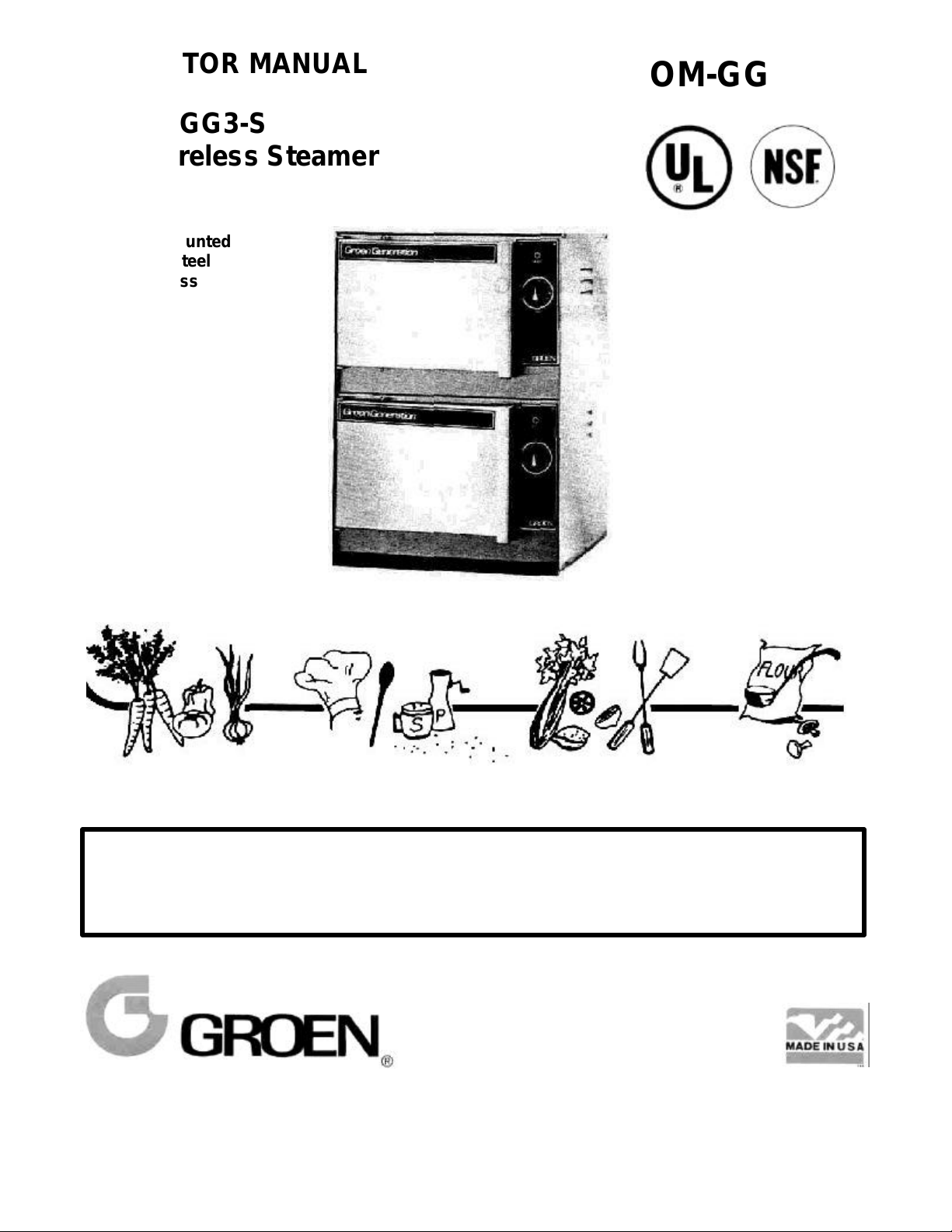
OPERATOR MANUAL
Model: GG3-S
OM-GG3-S
Pressureless Steamer
Cabinet mounted
Stainless steel
Pressureless
THIS MANUAL MUST BE RETAINED FOR FUTURE REFERENCE
FOR YOUR SAFETY
DO NOT STORE OR USE GASOLINE OR OTHER FLAMMABLE VAPORS
AND LIQUIDS IN THE VICINITY OF THIS OR ANY OTHER APPLIANCE
Page 2
LIMITED WARRANTY TO
COMMERCIAL PURCHASERS
(Continental U.S., Hawaii & Canadian Sales Only)
Groen Foodservice Equipment ("Groen Equipment") has been skillfully manufactured,
carefully inspected and packaged to meet rigid standards of excellence. Groen warrants
its Equipment to be free from defects in material and workmanship for (12) twelve
months, with the following conditions and subject to the following limitations.
This parts and labor warranty is limited to Groen Equipment sold to the original
I.
commercial purchaser/users (but not original equipment manufacturers), at its
original place of installation, in the continental United States, Hawaii and Canada.
II.
Damage during shipment is to be reported to the carrier, is not covered under this
warranty, and is the sole responsibility of purchaser/user.
III.
Groen, or an authorized service representative, will repair or replace, at Groen's
sole election, any Groen Equipment, including but not limited to, draw-off valves,
safety valves, gas and electric components, found to be defective during the
warranty period. As to warranty service in the territory described above, Groen will
absorb labor and portal to portal transportation costs (time & mileage) for the first
twelve (12) months from date of installation or fifteen (15) months from date of
shipment from Groen.
This warranty does not cover boiler maintenance, calibration, periodic adjustments
IV.
as specified in operating instructions or manuals, and consumable parts such as
scraper blades, gaskets, packing, etc., or labor costs incurred for removal of
adjacent equipment or objects to gain access to Groen Equipment. This warranty
does not cover defects caused by improper installation, abuse, careless operation,
or improper maintenance of equipment. This warranty does not cover damage
caused by poor water quality or improper boiler maintenance.
V. THIS WARRANTY IS EXCLUSIVE AND IS IN LIEU OF ALL OTHER
WARRANTIES, EXPRESSED OR IMPLIED, INCLUDING ANY IMPLIED
WARRANTY OF MERCHANTABILITY OR FITNESS FOR A PARTICULAR
PURPOSE, EACH OF WHICH IS HEREBY EXPRESSLY DISCLAIMED. THE
REMEDIES DESCRIBED ABOVE ARE EXCLUSIVE AND IN NO EVENT SHALL
GROEN BE LIABLE FOR SPECIAL, CONSEQUENTIAL OR INCIDENTAL
DAMAGES FOR THE BREACH OR DELAY IN PERFORMANCE OF THIS
WARRANTY.
VI.
Groen Equipment is for commercial use only. If sold as a component of another
(O.E.M.) manufacturer's equipment, or if used as a consumer product, such
Equipment is sold AS IS and without any warranty.
*(Covers All Foodservice Equipment Ordered after October 1, 1995)
Page 3
Table of Contents
EQUIPMENT DESCRIPTION……………………………………... 2
UNPACKING………………………………………………………... 3
INSTALLATION…………………………………………………….. 3,4,5
INITIAL START-UP…………………………………………………. 5
OPERATION…………………………………………………………
STYLE I………………………………………………………. 6
STYLE II……………………………………………………… 7
MAINTENANCE…………………………………………………….. 8
TROUBLESHOOTING……………………………………………... 9
REFERENCES……………………………………………………… 9
PARTS LISTS……………………………………………………….
STYLE I………………………………………………………. 10
STYLE II……………………………………………………… 11
DOOR ASSEMBLY………………………………………………… 12
DIAGRAMS AND SCHEMATICS…………………………………. 13
STYLE I………………………………………………………. 14
STYLE II……………………………………………………… 15
SERVICE LOG……………………………………………………… 16
WARRANTY………………………………………………………… 17
1
Page 4
Equipment Description
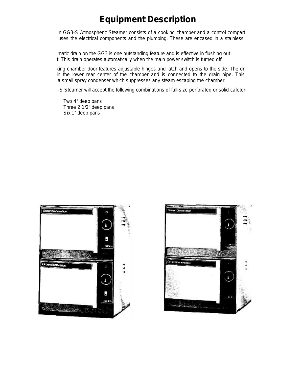
The Groen GG3-S Atmospheric Steamer consists of a cooking chamber and a control compartment
which houses the electrical components and the plumbing. These are encased in a stainless steel
cabinet.
The automatic drain on the GG3 is one outstanding feature and is effective in flushing out
sediment. This drain operates automatically when the main power switch is turned off.
The cooking chamber door features adjustable hinges and latch and opens to the side. The drain is
located in the lower rear center of the chamber and is connected to the drain pipe. This pipe
includes a small spray condenser which suppresses any steam escaping the chamber.
The GG3-S Steamer will accept the following combinations of full-size perforated or solid cafeteria
pans:
Two 4" deep pans
Three 2 1/2" deep pans
Six 1" deep pans
The GG3-S and GG3-SM steamers require an outside, food-safe steam source for their energy
supply. (Models GG3-SE and GG3-SG have generators built into their cabinet base.) The control
assembly can be accessed by removing only two screws and can be lifted out from the front. Power
should always be turned off before removing any panels.
The GG3-S Steamer is designed to be virtually maintenance-free; however, normal wear of certain
parts may require that they be replaced after prolonged use. This steamer has been adjusted at the
factory, therefore no field adjustment should be necessary. If need does arise for adjustment, only
authorized Groen service personnel should handle the work.
The GG3-S steamer is manufactured in two styles, which are easily distinguished by the presence
or absence of a power switch on the control panel.
GG3-S Style I GG3-S Style II
GG3-SG steamers and steamer-kettle combinations manufactured after January 1,1988 use Style
II.
All other GG3-S steamers and steamer-kettle combinations, including GG3-SG units manufactured
before January 1,1988 and GG3-S steamers supplied as stand-alone units, use Style I.
2
Page 5
Unpacking
The GG3-S Steamer will arrive completely assembled in either a box or a crate. Immediately upon
receipt, the box or crate should be inspected carefully for exterior damage and then opened. The unit
should then be inspected for concealed damage. Any shipping damage. Any shipping damage or
incorrect shipments should be reported to the delivering agent.
After inspection, the unit should remain crated until installation.
When installation is to begin, the crate or box should be removed from the skid. If the steamer has
been purchased separate from the base on which it will stand, the unit can then be hoisted onto its
mounting using a cloth-wrapped sling (to protect the polished surfaces).
If the steamer was shipped separate from its base, be certain to retain the four skid mounting bolts, as
they are required for installation.
WARNING: THE INSTALLATION OF THE GG3 STEAMER MUST BE DONE BY PERSONNEL
QUALIFIED TO WORK WITH ELECTRICITY AND PLUMBING. ALL APPLICABLE
CODES MUST BE ADHERED TO. IMPROPER INSTALLATION CAN CAUSE INJURY
TO PERSONNEL OR DAMAGE TO THE STEAMER.
Installation
NOTE: The general and plumbing connection instructions apply to a separately purchased steamer.
For a steamer-base combination (GG3-SE, GG3-SG, or GG3-SC), see the base unit operator
manual.
NOTE: Any mechanical or electrical change must be approved by the Groen Food Service En
gineering Department.
Once the GG3 Steamer has been removed from its crating and placed on the leveled table or counter
top, the unit should be secured by means of the skid mounting bolts provided. The bolts are to be
placed through the table top and secured into the anchor nuts on the steamer base. After the steamer
is securely in place, the joint between the base of the steamer and the table (or counter) top should be
sealed with a suitable caulking (such as RTV sealant).
NOTE: If the steamer is purchased with optional legs, they are to be screwed into the base anchor
nuts.
Now that the steamer has been secured in place the following service connections must be made by a
qualified service representative.
(For more information on connections and routing, also refer to the Diagrams and Schematics section
and the Parts Lists illustrations.)
Steam Connection
If the unit was purchased without a steam generator and requires direct steam service, connect the
steam line to the ½" NPT steam pipe located at the rear of the unit. The maximum steam flow rate
should be 104 Ib/hr at a pressure of 3 PSIG.
CAUTION: Supply must connect to a food-safe steam source.
3
Page 6
Water Connections
The "cold water" line (1/4" NPT) must be connected to the factory-supplied flexible hose.
Connect the hose to the steamer. The maximum condenser flow rate is 0.25 GPM (gallons
per minute). For optimum operating conditions, the main water supply flow rate should be
0.33 GPM at a pressure of 30 PSIG. Install a pressure reducing valve to accurately maintain
the required pressure and flow rate. GROEN also recommends that a strainer (user supplied)
be added in the water line.
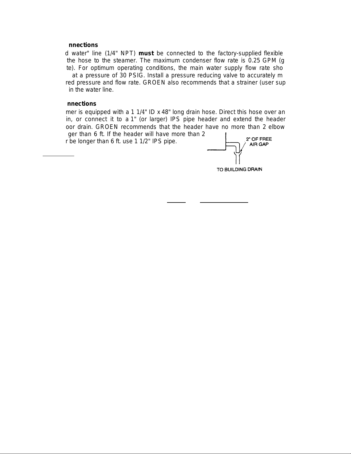
Drain Connections
The steamer is equipped with a 1 1/4" ID x 48" long drain hose. Direct this hose over an open
floor drain, or connect it to a 1" (or larger) IPS pipe header and extend the header to a
nearby floor drain. GROEN recommends that the header have no more than 2 elbows and
be no longer than 6 ft. If the header will have more than 2
elbows or be longer than 6 ft. use 1 1/2" IPS pipe.
Remember: This is a gravity drain that must be able to
vent freely to the atmosphere.
At the floor drain there must be an "air gap" of at least 2",
unless local codes specify a different gap. The drain must be set lower than the steamer
base.
CAUTION: The steamer drain discharges steam and hot condensate. To direct the flow of
the condensate to the floor drain, comply with these instructions and recommendations.
Electrical Connections
The GG3-S Steamer uses an electrical connection of 115 VAC, 1 phase, 50/60 Hz, and 15 amps.
The wires are to be connected to the terminal block inside the junction box located at the rear of the
unit. Use 14 gauge (1.8 mm) copper wire rated at least 75°C. Local codes and/or The National
Electrical Code should be observed in accordance with ANSI/NFPA-70, latest edition.
For Model GG3-SE (self-contained electric generator) refer to electrical requirements in cabinet
base manual.
Gas Connection
For Model GG3-SG (self-contained gas generator) refer to cabinet base operator manual.
4
Page 7

Connection Locations/Piping
SINGLE UNIT DOUBLE STACK
A - TERMINAL BLOCK BOX
B - CONDUIT CONNECTION
C - DRAIN CONNECTION
D - COLD WATER CONNECTION
E - STEAM CONNECTION
NOTE: For separately purchased steamers. For GG3-SE,
GG3-SG or GG3-SC, see cabinet base operator
manual.
Initial Start-Up
Now that the steamer has been installed, the installer should test to ensure that the unit is operating
correctly.
1. Remove all literature and packing from the interior and exterior of the unit.
2. Be sure water and/or steam supply lines to the steamer are open.
3. Turn on electrical service to the unit.
4. Verify that the strainer for the chamber drain and all of the pan supports are in place.
5. Style I only: Push the power switch to the ON position. The switch will illuminate, indicating that
power is on.
6. Set the timer for approximately 5 minutes. Steam should be visible after about 3 minutes of
operation.
7. To turn off the alarm at the end of the timing cycle, set the timer to zero. Style I only:
To completely shut down the unit push the power switch to the OFF position. (The light will go out).
If the steamer has functioned as described above the unit is ready for use. If the steamer does not
function as intended, call your local Groen Authorized Service Agent.
5
Page 8

Operation
Style I
The operator controls are located on the front right side of the unit. The power switch is used to
ready the steamer for use, and to shut the unit off. For frequent use, the unit may be left on. The
60-minute timer is the only control which has to be operated. Turning the timer knob sets the
desired steaming time.
A. Start-Up Procedure
1. Make sure steam is available. (If you have a self-contained generator, see the cabinet base
operator manual.)
2. Push the power switch to the ON position.
3. Set the timer past 5 minutes to warm up the unit.
B. Operation
1. Load food into pan so that there is a uniform layer. Slide pan onto supports. Use middle pan
position when only using single pan.
2. Close door.
3. Set timer at the desired cooking time. To set a steaming time shorter than 5 minutes, turn the
knob past 5, then back to the desired setting. The optimum time can only be determined by test,
due to influence of initial product temperature, amount of product, water or ice present, thickness
of layer, etc. (See recommended Cook Time Chart provided for approximate settings.)
4. Alarm will sound, ready lamp will light, and steam will cut off when set time has elapsed.
5. To stop alarm, turn timer knob to zero position.
WARNING: STEAM CAN CAUSE BURNS. USE CARE WHEN OPENING DOOR
TO CHECK OR REMOVE FOOD.
For best results in steam cooking, be sure that operator understands how to use Steamer and that
proper maintenance and daily cleaning are performed by a qualified person.
C. Cleaning
At the end of the day, both the interior and exterior of the steamer should be cleaned. See "Maintenance" section of this manual.
6
Page 9

5 - PAN SUPPORTS
9 -
TIMER
10 -
READY LAMP
11 -
POWER SWITCH
24 -
DRAIN SCREEN
Style II (only for GG3-SG built after 1/1/88)
The operator control is located on the front right side of the unit. The 60-minute timer is the only control
which has to be operated. Turning the timer knob both starts steam flow and sets desired steaming time.
When this time has elapsed, an alarm will sound continuously until the knob is turned to the zero
position. If further steaming is required, turn the timer knob to the additional time required. The ready
lamp will light at finish of elapsed time.
A. Start-Up Procedure
1. Make sure steam is available. (See the cabinet base operator manual.)
2. Set the timer past 5 minutes to warm up the unit.
B. Operation
1. Load food into pan so that there is a uniform layer. Slide pan onto supports. Use middle pan position
when only using single pan.
2. Close door.
3. Set timer at the desired cooking time. To set a steaming time shorter than 5 minutes, turn the
knob past 5, then back to the desired setting. The optimum time can only be determined by test,
due to influence of initial product temperature, amount of product, water or ice present, thickness
of layer, etc. (See recommended Cook Time Chart provided for approximate settings.)
4. Alarm will sound, ready lamp will light, and steam will cut off when set time has elapsed.
5. To stop alarm, turn timer knob to zero position.
WARNING: STEAM CAN CAUSE BURNS. USE CARE WHEN OPENING DOOR TO
CHECK OR REMOVE FOOD.
For best results in steam cooking, be sure that operator understands how to use Steamer and that
proper maintenance and daily cleaning are performed by a qualified person.
C. Cleaning
At the end of the day, both the interior and exterior of the steamer should be cleaned. See "Maintenance"
section of this manual.
(Style I only. No switch on Style II)
7
Page 10

Maintenance
The GG3 Steamer is designed for minimum maintenance, but certain parts may need replacement
after prolonged use. Always use low-mineral water for the water supply. No user adjustment should
be necessary. If a service need arises, only authorized personnel should perform the work.
WARNING: ELECTRIC POWER SHOULD ALWAYS BE SHUT OFF BEFORE
WORK ON INTERNAL COMPONENTS IS BEGUN.
If the steamer is cooking slowly, check steam pressure on Models GG3-SM & GG3-SC. Check the
electric heating element on Model GG3-SE and heat transfer surfaces on Model GG3-SG for scale
buildup. (See Self-Contained Boiler Manual.) Also, check the water supply (where applicable) and the
strainer in the water inlet.
If at any time, the electrical components need to be checked, they can be accessed through the
removable panel on the front of the unit.
Fuses for the steamer are located on the rear panel. Should they ever need to be replaced, the fuse
knob can be unscrewed to expose the fuse, and the user can then pull out the fuse and replace it.
In order to keep the GG3 in proper working condition, the unit should be cleaned daily using the
following procedure.
Daily Cleaning Program
WARNING: TAKE PRECAUTIONS TO AVOID CONTACT WITH THE CLEANER,
AS RECOMMENDED BY THE SUPPLIER. MANY CLEANERS ARE
HARMFUL TO THE SKIN, EYES, MUCOUS MEMBRANES, AND
CLOTHING. CAREFULLY READ THE WARNINGS AND FOLLOW
THE DIRECTIONS ON THE LABEL OF THE CLEANER.
WARNING: BEFORE YOU BEGIN TO CLEAN THE UNIT, DISCONNECT THE
ELECTRIC POWER SUPPLY AT THE CIRCUIT BREAKER OR
FUSE BOX.
1. Shut off power.
2. Allow steamer to cool.
3. Wash the racks and then the entire compartment interior using a mixture of warm water and a mild
detergent.
4. Rinse the cooking chambers thoroughly with warm water. Make sure the drain screen is clean and
free of food particles.
5. Wipe down the exterior surfaces with a damp rag, being careful not to allow any moisture to enter
the control panel.
6. Leave the chamber door open long enough to allow the chamber to dry completely.
CAUTION: Do not use abrasive cleaning materials such as steel wool on the
unit. To preserve the stainless steel surface use only plastic or
stainless wool or any type of cloth.
CAUTION: Control panel is not waterproof. Do not steam clean or hose down.
Door Latch Adjustment
If steam or condensation is noticed leaking from around the door seal, and inspection of the cooking
chamber drain shows no blockage, the door requires adjustment. All gaskets will creep at temperatures like those found in a steamer. Groen has designed an adjustable latch on the door to compensate for gasket compression and aging.
To make an adjustment, loosen the two latch nuts and move the latch catch plate toward the handle,
decreasing the space between the chamber and the door gasket on the right side of the steamer.
Tighten the nuts securely.
8
Page 11

Troubleshooting
go on (Style
1
only).
contained generator manual to
troubleshoot steam source problem.
The GG3 Steamer is designed to operate smoothly and efficiently if well-maintained. However, there
may be small problems. In the event of a problem, refer to the following checklist.
CAUTION: Use of any replacement parts other than those supplied by Groen or their
authorized distributor VOIDS ALL WARRANTIES and can cause bodily
injury to the operator and damage to the equipment. Service performed
by other than factory authorized personnel WILL VOID ALL
WARRANTIES.
SYMPTOM WHAT TO CHECK
Main power switch light does not
No steam. a. Check self-
Excess water or steam coming
out of front of chamber.
a. Electric supply line, etc.
a. For food lodged in drain of chamber.
b. Door adjustment
NATIONAL FIRE PROTECTION ASSOCIATION
60 Battery March Park
Quincy, Massachusetts 02269
NFPA/70 The National Electrical Code
References
9
Page 12

Style I Parts Lists
To order parts, contact your authorized Groen Service Agency. Supply the model designation, part
description, part number, quantity, and where applicable, voltage and phase.
ITEM PART ITEM PART
NO. NO. DESCRIPTION NO. NO. DESCRIPTION
3 50804 DOOR ASSEMBLY (see separate parts list) 16 10873 CLAMP HOSE 1 3/8"
6 26588 LAMP PILOT 17 27599 HOSE 4" LG, DRAIN
7 27167 PANEL DECAL FOR 60 MIN. CW TIMER 18 3485 PAN 12 x 20 x 2 1/2 DP. PERF (OPT.)
8 73619 TIMER, 60 MIN. 19 14355 SAFETY VALVE
9 16166 SWITCH, POWER ON/OFF 20 25964 SUPPORT TRAY
10 3360 BUZZER.120V.60HZ 22 40225 KNOB, BLACK
11 3522 TERMINAL STRIP 24 2972 PAN FULL SIZE PERF. 20 3/4"x 12 3/4"x4" DP (OPT.)
12 41121 LEGS 4" HIGH (OPTIONAL) 28 41123 SCREEN, DRAIN (NOT SHOWN)
13 50790 CATCH ASSEMBLY 29 44580 PAN SOLID FULL 20 3/4" x 12 3/4" x 2 1/2" DP (OPT.)
14 3460 SOLENOID VALVE 30 4511 HOSE, WATER FEED
15 3363 SOLENOID VALVE 31 70220 STEAM BAFFLE
10
Page 13

Style II (only GG3-SG built after 1/1/88)
11
ITEM
PART
DESCRIPTION
PANEL FACE PLATE ASSY
ITEM
PART
DESCRIPTION
3 50804 DOOR ASSY (see separate parts list)
6 26588 PILOT LAMP
7 74589
8 78619 TIMER 60 MINUTES
9 70220 MANIFOLD ASSY
10 71270 HOSE BARB 1/8
11 77994 HOSE 3/8" ID x 22"LG
12 41121 LEGS 4" HlGH
13 50790 CATCH ASSY
14 71271 HOSE CLAMP
15 69732 HOSE BARB 1/4" MPT X ID
16 14360 TEE 1/4"" NPT
17 3923 NIPPLE 1/4" NPT X CLOSE
18 3485 PAN 12 x 20 x 2 1/2" DP PERFORATED (OPT.)
19 14355 SAFETY VALVE
20 25964 TRAY SUPPPORT
22 40225 KNOB BLACK
24 2972 PAN FULL SIZE PERFORATED x 4" DP (OPT.)
28 41123 SCREEN DRAIN
29 44580 PAN FULL SIZE SOLID x 2 1/2"" DP
30 3922 ELBOW 90 DEG. ST. 1/4" NPT.
31 62965 TUBING COPPER 3/OD X 24- LG
32 78623 ELBOW 90 DEG. 1/4" MPT X 3/8" TUBE COMP. FIT.
33 77981 VALVE SOL. SPRAY 1/4" NPT
34 74216 NOZZLE SPRAY 1/8" MPT
35 78621 ELBOW 3/NPT X 90 DEG. (SPECIAL)
36 77992 DRAIN NIPPLE 3/NPT. T.O.E.
37 73259 HOSE CLAMP
38 77993 HOSE 199/16 " OD X 1" ID X 3" LG
39 77989 ELBOW (SPECIAL) 90 DEG. W/O PIPE THREAD
40 77979 TUBING 1/2" OD COPPER X 14" LG
41 55335 ELBOW 90 DEG. 3/8" MPT X TUBE COMP. FIT.
42 74593 TEE 1/2" X 1/2MPT ((2) GG3-S unit only)
43 77982 VALVE STEAM SOLENOID 3/NPT
44 13202 3/8"NPT CLOSE NIPPLE
45 42364 ELBOW 90 DEG. STREET 3NPT
46 27276 TEE REDUCING 3/NPT
47 10863 NUT TRU-SEAL
48 70221 NIPPLE ASSY (SPECIAL)
49 70227 RUBBER O-RING
50 77995 HOSE 3/ID X 35" LG (FOR (2) GG3-S UNIT)
51 77986 TEE (SPECIAL) W/O PIPE THREAD
Page 14

Door Assembly
ITEM
NO.
10 50787 BAR RETAINING DOOR FOR INNER DOOR
11 50806 SPRING ASSEMBLY INNER
12 50802 PANEL INNER DOOR 16GA
13 50856 PANEL ASSY GASKET FOR 25987 GASKET
14 25987 DOOR GASKET, OLD STYLE – EXTRUDED AND ROUNDED
15 12940 NUT HEXAGON KEPS
PART
NO.
1 13466 SCREW ROUND HEAD 1/4-20 x 3/4"
2 54599 SPRING DOOR AT BOTTOM OF HANDLE
3 50795 LATCH ASSY GG3 DOOR
4 55248 WASHER FIBER 1/4" ID
5 50797 HANDLE ASSY GG3 DOOR
6 51246 PANEL ASSY OUTER DOOR
7 50789 BAR ROUND FOR DOOR
8 40220 BEARING FLANGED .376"
9 50796 HINGE DOOR GG3/GG4
62876 PLATE GASKET RETAINING FOR 62874 GASKET
62874 GASKET, DOOR, NEW STYLE – FLAT AND SPONGEY
DESCRIPTION
Page 15

Style I
Diagrams and Schematics
Piping Schematic
Piping Furnished By User
13
Page 16

Style I
Wiring Diagram
14
Page 17

Style II
Wiring Diagram
TIMER SIDE VIEW
15
Page 18

Service Log
Model No. __________________ Purchased From________________
Serial No.____________________ Location ____________________
Date Purchased _________________ Date Installed __________________
Purchase Order No. ______________ For Service Call ________________
Date Maintenance Performed Performed by
16
 Loading...