

Page 1
OPERATOR MANUAL
Model: GG3-E
Pressureless Steamer
Table top
Self-contained
Electric Three (2 1/2 in. deep)
pan capacity
OM-GG3-E
THIS MANUAL MUST BE RETAINED FOR FUTURE REFERENCE
FOR YOUR SAFETY
DO NOT STORE OR USE GASOLINE OR OTHER FLAMMABLE VAPORS
AND LIQUIDS IN THE VICINITY OF THIS OR ANY OTHER APPLIANCE.
Page 2

IMPORTANT —— READ FIRST —— IMPORTANT
The Groen Generation 3 pressureless steamer you have purchased has been handcrafted from
the finest materials, meticulously inspected, and pretested at our factory to ensure that you
receive the best possible product. With reasonable care and periodic maintenance, it will provide
years of faithful service.
PLEASE READ THIS MANUAL CAREFULLY BEFORE INSTALLING OR OPERATING THE
GENERATION 3 STEAMER! It contains all the information you will need to properly install,
operate, and maintain your steamer.
It is recommended that you establish a timetable for periodic maintenance as outlined in this
manual. Space has been provided in the Maintenance & Service Log. Keep it up-to-date and on
file with the warranty information.
Please pay special attention to the section on WATER CONDITIONING. Water quality problems
are the most common cause of steamer failure and are not covered by provisions of the product
warranty.
CONDITIONS AND TERMS OF LIMITED WARRANTY
The warranty on this unit does not extend to:
1. Installation and start-up.
2. Simple adjustments, such as tightening fittings and electrical connections.
3. Malfunction as a result of improper maintenance.
4. Repairs made by anyone other than qualified service personnel as recommended by Groen.
5. Damage caused in shipment or damage as a result of improper use.
6. Normal maintenance as outlined in the operator manual.
7. Damage as a result of excessive moisture in components. DO NOT SPRAY THIS EQUIP-
MENT WITH WATER OR STEAM.
8. Damage caused by tampering with, removal of, or change of any pre-set control or safety
device.
9. Malfunction as a result of sediment and/or lime in the valves or scale build-up in the steam
generator.
NOTE: MINIMUM water quality STANDARDS MUST BE MET to insure proper operation.
WATER SOFTENING IS RECOMMENDED if the quality of your water does not meet
the following standards.
Total dissolved solids (TDS) content should not exceed 30 parts per million, and
water pH should be 7.0 or higher.
10. Labor involved in moving other equipment to gain access to the unit. The user must
maintain the accessibility of the steamer for service under the warranty.
CAUTION: Use of any replacement parts other than those supplied by Groen or their
authorized distrubutor VOIDS ALL WARRANTIES. Service performed by
other than factory authorized personnel WILL VOID ALL WARRANTIES.
If you have any questions about warranty coverage, operating procedure, or maintenance, contact
your area Groen representative or an authorized Groen service agency.
Page 3

Table of Contents
EQUIPMENT DESCRIPTION 2
WATER CONDITIONING 3
INSTALLATION 4, 5
DIAGRAMS & SCHEMATICS 6, 7, 8, 9, 10
INITIAL START-UP 11
OPERATION 12
SEQUENCE OF OPERATION 13
MAINTENANCE & CLEANING 13,14
TROUBLESHOOTING 15
PARTS LIST 16, 17, 18, 19
REFERENCES 19
MAINTENANCE LOG 20
WARRANTY 21
1
Page 4

Equipment Description
The Groen GG3-E Self-Contained Atmospheric Steamer consists of a cooking chamber, a steam generator
with heating element, and a control compartment housing the electrical components and plumbing, all
encased in a stainless steel cabinet.
Two outstanding features on the GG3 are the automatic drain and stand-by power. As long as the main
power switch is on and the boiler is warmed up, stand-by power (about 2% of full power) is fed to the heating
element to keep the boiler water at incipient boil and ready for immediate full-steam generation. The
automatic drain feature operates after the main power switch has been turned off. The unit will drain
completely to flush sediment out of the steam generator.
The drain is located in the lower rear center of the chamber and is connected to the drain pipe. The pipe
includes a spray condenser, which suppresses any steam escaping the chamber. A small tray below the door
is provided to catch any condensate drip.
Model GG3-E will accept the following combinations of full-size perforated or solid cafeteria pans:
Two pans, 4" deep
Three pans, 2 1/2" deep
Six pans, 1"deep
The steam generator compartment is located behind the cooking chamber and is accessible through the right
side panel. The control assembly can be accessed from the front panel and can be lifted out. Power should
always be turned off before removing any panel.
The steam generator functions in a simple manner. A normally-closed solenoid valve opens and allows water
to enter until the proper level is sensed. The solenoid valve then closes, and the water is quickly converted to
steam by the heating element. This function is repeated when necessary, as long as the timer is in the timing
position.
The GG3-E Steamer is designed to be virtually maintenanace-free; however, normal wear of certain parts
may require that they be replaced after prolonged use. This steamer has been adjusted at the factory, so no
field adjustment should be necessary. If need for adjustment does arise, only Groen personnel or Groen's
authorized representatives should handle the work.
2
Page 5

Water Conditioning
It is absolutely essential to supply the Groen steamer with water that will not form scale at an unacceptable
rate. The steam generator was engineered to minimize scale formation, but scale formation depends on the
hardness of the water and the hours of operation. In a few areas of the United States, the water supply is
sufficiently free of minerals to avoid scale formation. However, most water supplies carry heavy loads of
minerals, which will form scale on the generator, reduce its steam output, and possibly cause premature
failure of components.
Your local water utility can provide a statement on the scale forming qualities of the water supply. Water
supplied to the generator should contain not more than 30 parts per million total dissolved solids (TDS) and
should have a ph of 7.0 or higher. Please follow these simple precautions:
1. Do not rely on "water treaters" commonly sold as scale preventers and scale removers. They do not
work. The only proven way to prevent scale build-up is to feed in water practically free of scale-forming
minerals.
2. If your water supply carries scale forming minerals, as most water supplies do, run the water through a
properly maintained softener. Exchangeable softener cartridges or a regeneratable softener can be used.
In either case, establish a regular program of exchanging the cartridges or regenerating the softener.
Installing a water meter on the inlet line between the softener and the generator will give an accurate
check of water consumption and a way of determining when to change the cartridge or regenerate the
softener.
By using a softener and operating within the softener's capacity to exchange minerals, the user will obtain
a longer generator life, high steam capacity, and minimum maintenance requirements.
3. If you notice a slowing of steam production, pull the heating element out of the steam generator and
check it for scale.
WARNING: DISCONNECT ELECTRIC POWER BEFORE YOU REMOVE THE CASING FROM THE
STEAMER.
Heavy scale will reduce the element's ability to boil water and can elevate element temperature to the point
where the element will fail prematurely.
Some scale is soft enough to be scraped off, but scraping must be done carefully to avoid damaging the
element bars or safety thermostat. Cleaning with sulfamic acid, inhibited muriatic acid, or another
commercially available deliming agent can be dangerous and should be done only by an expert familiar
with the hazards. Vinegar will dissolve most scales, but the treatment requires a long time and frequent
changes of the vinegar solution.
TO AVOID ALL SCALE PROBLEMS, USE AND PROPERLY MAINTAIN A SOFTENER.
3
Page 6
Installation
Mounting
After the inspection, keep the unit crated until it is installed.
When installation is to begin, remove the crate or box from the skid. Remove the four mounting bolts that
fasten the skid to weld nuts in the base of the steamer. Keep the bolts, as they are required for installation.
Hoist the unit to its mounting location with a cloth-wrapped sling (to protect the polished surfaces).
Level the table top or counter on which the GG3 Steamer will be mounted. Unless the optional legs will be
used, drill four holes (of 1/2 inch diameter) that will align with the anchor nuts welded into the steamer base. If
service connections will be made through the mounting surface, also drill holes for those supplies at this time.
Once the steamer has been removed from its shipping container and placed on the leveled mounting surface,
secure the unit with the skid mounting bolts saved during unpacking. After the steamer has been bolted in
place, seal the joint between steamer base and mounting surface with a suitable caulking compound like RTV
sealant.
If the steamer was purchased with optional legs, screw the legs into the anchor nuts on the base.
WARNING: THE STEAMER MUST BE INSTALLED BY PERSONNEL QUALIFIED TO WORK WITH
ELECTRICITY AND PLUMBING. IMPROPER INSTALLATION CAN CAUSE INJURY TO
PERSONNEL AND/OR DAMAGE TO THE EQUIPMENT. INSTALL THE UNIT IN
ACCORDANCE WITH ALL APPLICABLE CODES.
CAUTION: To avoid damage to the steamer and possible voiding of warranties, follow the directions in
the "Water Conditioning"section before you connect the water supply.
Water Connections
Connect the cold water line (1/4 inch NPT) to the factory-supplied flexible hose, then connect the hose to the
steamer. A check valve must be installed, and some codes require a second check valve. (See the piping
diagrams.) To maintain the required pressure and flow rate accurately, install a strainer and a pressure
reducing valve. The required flow rate at 30 PSIG is 0.28 to 0.33 GPM tor the 5 KW steamer or 0.31 to 0.36
GPM for the 7.5 KW steamer.
Drain Connections
The steamer is equipped with a 1 1/4" ID x 48" long drain hose. Direct this hose over an open floor drain, or
connect it to a 1" (or larger) IPS pipe header and extend the header to a nearby floor drain. GROEN
recommends that the header have no more than 2 elbows and be no longer than 6 ft. If the header will have
more than 2 elbows or be longer than 6 ft, use 1 1/2" IPS pipe.
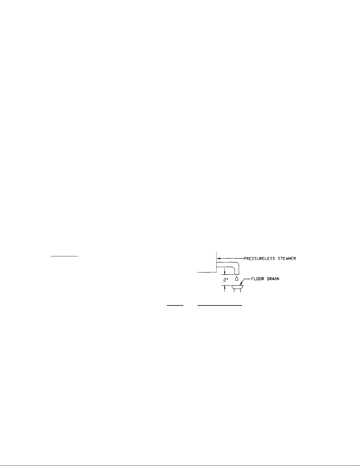
Remember: This is a gravity drain that must be able to vent
freely to the atmosphere.
At the floor drain there must be an "air gap" of at least 2",
unless local codes specify a different gap. The drain must be
set lower than the steamer base.
CAUTION: The steamer drain discharges steam and hot condensate. To direct the flow of
the condensate to the floor drain, comply with these instructions and recommendations.
Electrical Connections
Any mechanical or electrical change must be approved by the Groen Division Food Service Engineering
Department. The required electrical supply is protected by fuses in the steamer and is specified on an
information plate at the rear of the unit. Power must be connected to a terminal block inside the junction box
in the rear of the steamer. Stacked units require separate electrical connections for each unit. Local codes
and/or The National Electrical Code should be observed in accordance with ANSI/NFPA-70 latest edition.
GG3-E Steamers are shipped with 3 phase wiring. For field conversion to single phase operation, consult the
label on the rear of the unit or the diagram included in this manual.
4
Page 7
ELECTRICAL REQUIREMENTS
208V, 1PH 24
208V, 3 PH 14
240V, 1PH 21
240V, 3 PH 12
480V, 1PH 10.4
480V, 3 PH 6
AMP WIRE SIZE
5KW 7.5 KW
NOTE: Use copper wire rated at least 75°C.
#8AWG (3.5mm)
#8AWG (3.5mm)
#10AWG (3.0mm)
#10AWG (3.0mm)
#12AWG (2.5mm)
#12AWG (2.5mm)
WIRE SIZE
36
21
31
18
16
9
#6AWG (4.5mm)
#6AWG (4.5mm)
#6AWG (4.5mm)
#6AWG (4.5mm)
#12AWG (2.5mm)
#12AWG (2.5mm)
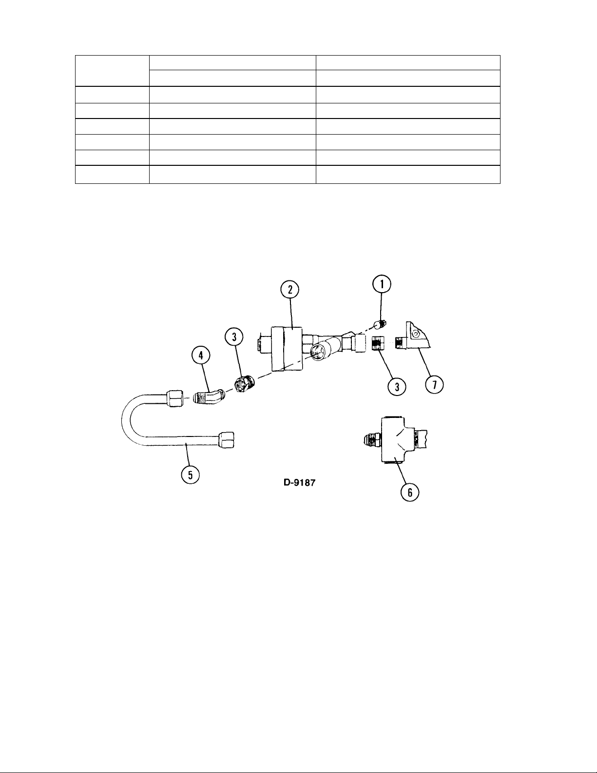
New Dump Solenoid Valve
1) Starting with solenoid valve (2) screw 1/4 NPT pipe plug (1) into solenoid valve 1/4 FPT inlet.
2) Screw 1/2 x 3/8 reducing bushing (3) into 1/2 FPT inlet of solenoid valve (2).
3) Screw solenoid valve with reducing bushing into boiler outlet % NPT (7).
4) Screw 1/2 x 3/8 reducing bushing (3) and 45° elbow (4) respectively into solenoid valve (2) 1/2 NPT outlet.
5) Attach 1/2 O.D. copper tubing (5) short run to elbow (4) and long run to drain (6).
6) Rotate solenoid valve (2) on horizontal axis to assemble 1/2 O.D. copper tubing.
5
Page 8

Mounting Hole Dimensions
6
Page 9

Connection Locations / Piping
A - TERMINAL BLOCK
B - CONDUIT CONNECTION
C - FUSES
D - WATER FEED HOSE
E - DRAIN HOSE
SINGLE UNIT
DOUBLE STACKED UNIT
7
Page 10

Piping Schematic
8
Page 11

Piping Furnished By User
NOTE : CONSULT LOCAL CODES
9
Page 12

Wiring Diagrams
10
Page 13

Initial Start-Up Of The GG3
Now that the steamer has been installed, the initial testing to ensure that the unit is operating correctly
should performed.
1. Remove all literature and packing from the interior and the exterior of the unit.
2. Be sure water line to the steamer is open.
3. Turn on electrical service to the unit.
4. Verify that the strainer for the chamber drain and all of the pan supports are in place.
5. Push the ON/OFF power switch to the ON position. Switch will illuminate, indicating that
power is on.
6. Set the timer for approximately 5 minutes. Steam should be visible after about 3 minutes
of operation. Check condensate drain to ensure proper drainage.
7. To turn off the alarm at the end of the timing cycle, set the timer to zero.
To completely shut down the unit push the ON/OFF power switch to the OFF position. (The light will go
out and the steamer will automatically start to drain.)
If the steamer has functioned as described above the unit is ready for use. If the steamer does not function
as intended, call your Groen Authorized Agent.
11
Page 14

Operation
The operator controls are located on the front right side of the unit. The power switch is used to ready the
steamer for use, and to shut the unit off. For frequent use, the unit may be left on. The 60-minute timer is the
only control which has to be operated. Turn the knob to the desired time. When this time has elapsed, an
alarm will sound continuously until the knob is turned from the alarm mode to the OFF position. If further
steaming is required, turn the timer knob to the additional time required. The ready lamp will light at finish of
elapsed time.
A. Start-up Procedure
Push power switch to the ON position. Set timer to 5 minutes to fill steam generator and warm up the
unit.
B. Cooking
1. Load food into pan so that there is a uniform layer. Slide pan onto supports. Use middle pan position
when only using one pan.
2. Close door.
3. Set timer at the desired cooking time. The optimum time can only be determined by test due
to influence of initial product temperature, amount of product, water or ice present, thickness
of layer, etc. (See recommended Cook Time Chart provided for approximate settings.)
4. Alarm will sound, ready lamp will light, and steam will cut off when set time has elapsed.
5. To stop alarm, turn timer knob from alarm mode to OFF position.
WARNING: STEAM CAN CAUSE BURNS. USE CARE WHEN OPENING DOOR TO CHECK OR
REMOVE FOOD.
For best results in steam cooking, be sure that operator understands how to use GG3 Steamer, and that
proper maintenance and daily cleaning are performed by a qualified person.
C. Cleaning
At the end of the day, both the interior and exterior of the steamer should be cleaned. See the Maintenance
& Cleaning section of this manual for instructions.
12
Page 15

Sequence Of Operation
The following outline is provided as a means for better understanding the actual functioning of the steamer.
This "action-reaction" type of outline should guide the user through operational steps.
When the power switch is turned on and the timer is set to "O", the ready lamp will light, the dump valve will
close, and the water fill valve will open, filling the steam generator until the probe senses the proper water
level. When the timer is set at a cooking time, full power will flow to the heating element and the condenser
water will start to flow. If the water level does not reach the level-sensor probe within about 5 seconds, the
power to the heating element and the condenser water will automatically be turned off until water reaches the
probe.
During the cooking time, the probe will sense when water is needed and will open and close accordingly.
When the cooking time has elapsed, the alarm will sound and can be silenced by turning the timer back to
"OFF". Also, at the end of the cooking period, the current to the element is turned off, the ready lamp will
come on, and the condenser water will shut off. If the timer is not reset for a cooking cycle, after
approximately 4 minutes, the stand-by power (2% of full power) will be applied to the heating element so that
the water in the boiler will remain at incipient boil and the unit will be ready for immediate cooking.
If the water feed fails, check for blockage (see Page 13) When the water level has fallen below the probe for
more than about 5 seconds, all power will be removed from the heating element and will remain off until the
water level is restored. At restoration, if the timer is set at zero, stand-by power will come on in about 4
minutes and, because of its low imput (2%), it will slowly warm up the new water in the boiler. To offset this
delay, after the water supply has been restored, set the timer for a 5-minute warm-up.
If the heating element overheats due to control failure, or low water, a safety thermostat in the element will
cut off all power and automatically reset only after the element has cooled to a safe temperature. At that time,
power to the element will resume. If the water has not been restored, the element will quickly overheat again,
and the thermostat will again cut off the power.
When the main power switch is turned off, all power is removed from the heating element and the control
circuit downstream from the switch. Also, the dump valve will open and allow the steam generator to drain. If
condenser water is flowing at this time, it will be turned off.
Maintenance & Cleaning
The GG3 Steamer is designed for minimum maintenance, but certain parts may need replacement after
prolonged use. Always supply low-mineral water. No user adjustment should be necessary. If a service
need arises, only Groen personnel or authorized Groen representatives should perform the work.
CAUTION: Use of any replacement parts other than those supplied by Groen or their authorized
distributor VOIDS ALL WARRANTIES and can cause bodily injury to the operator and
damage to the equipment. Service performed by other than factory authorized personnel
WILL VOID ALL WARRANTIES.
WARNING: ALWAYS SHUT OFF THE ELECTRIC POWER BEFORE WORK IS DONE ON
INTERNAL COMPONENTS .
13
Page 16

If the steamer is cooking slowly, check the heating element for scale build-up and clean or replace it as
necessary. Also, check the water supply. If the heating element is in good condition, check the strainer in the
water inlet. The strainer is found in the right lower corner of the control compartment. Remove the nut on the
strainer, pull out the screen, and clean it out.
If the electrical components need to be checked, they can be reached through the removable panel on the
front of the unit.
Fuses for the steamer are located on the rear panel. Should they ever need to be replaced, the fuse knob
can be unscrewed to expose the fuse. The user can then pull out the fuse and replace it.
Door Latch Adjustment
If steam or condensation is noticed leaking from around the door seal, and inspection of the cooking chamber
drain shows no blockage, the door requires adjustment. All gaskets will creep at temperatures like those
found in a steamer. Groen has designed an adjustable latch on the door to compensate for gasket
compression and aging.
To make an adjustment, loosen the two latch nuts and move the latch catch plate toward the handle,
decreasing the space between the chamber and the door gasket on the right side of the steamer. Tighten the
nuts securely.
Daily Cleaning Program
WARNING: TAKE PRECAUTIONS TO AVOID CONTACT WITH THE CLEANER, AS RECOM-
WARNING: BEFORE YOU BEGIN TO CLEAN THE UNIT, UNPLUG THE POWER SUPPLY CORD,
To keep the GG3 in proper working condition, clean the unit daily by the following procedure.
1. Shut off the power.
2. Allow the steamer to cool.
3. Wash the racks and then the entire cooking chamber interior with a mixture of warm water and
a mild detergent.
WARNING: DO NOT HOSE OR STEAM CLEAN THE UNIT. THE CONTROL PANEL IS NOT
4. Rinse the cooking chamber thoroughly with warm water. Make sure that the drain screen is clean
and free of food particles.
5. Wipe the exterior surfaces clean with a damp rag. Be careful to keep all the moisture out of the
control panel.
6. Leave the chamber door open long enough to allow the chamber to dry completely.
MENDED BY THE SUPPLIER. MANY CLEANERS ARE HARMFUL TO THE SKIN, EYES,
MUCOUS MEMBRANES, AND CLOTHING. CAREFULLY READ THE WARNINGS AND
FOLLOW THE DIRECTIONS ON THE LABEL OF THE CLEANER.
OR DISCONNECT THE ELECTRIC POWER SUPPLY AT THE CIRCUIT BREAKER OR
FUSE BOX.
WATERPROOF.
CAUTION: Do not use abrasive cleaning materials like steel wool or scouring powder on the unit. To
preserve the stainless steel surfaces, wash them with cleaning aids such as cloth, plastic
wool, or a soft-bristle brush.
14
Page 17

Troubleshooting
SYMPTOM
WHAT TO CHECK
The GG3 Steamer is designed to operate smoothly and efficiently if properly maintained. However, in the
event of a problem, the following list of checks may be employed. If an item on the list is followed by an
asterisk (*), the work should be done only by a factory authorized service representative.
WARNING: USE ONLY GROEN SUPPLIED PARTS. SUBSTITUTION OF UNAUTHORIZED
PARTS OR GENERIC PARTS CAN CAUSE BODILY INJURY TO THE
OPERATOR AND DAMAGE TO THE EQUIPMENT.
Power switch light does not go on. a. Fuses on the back panel of the cabinet.
b. Electric power supply.
No steam. a. Water supply to the steamer.
b. Strainer for plugged screen (Ref. 23).*
c. Fill valve operation (Ref. 22).*
d. Contactor operation (Ref. 12).*
e. Thermostat operation (Ref. 14).*
f.
g.
h. For power through the timer (Ref. 5).*
Excess steam in the drain. a. For a clogged spray nozzle in the drain piping .*
b. Drain solenoid operation (Ref. 24).*
Excess water or steam coming out the a. For a clogged drain.
front of the chamber.
b. Pitch of the steamer. Check by placing a spirit
level on the floor of the chamber.
c. Door adjustment.*
Water level sensor rod for build-up of scale
(Ref. 18, 19).*
Heating element for ground short or open
element (Ref. 39).*
15
Page 18

Page 19

HEATING ELEMENTS
42356
208 V, 3
PH,
60
HZ, 5 KW
ITEM
NO.
1 3360 BUZZER
2 26588 LAMP. PILOT
3 40225 KNOB, BLACK
4 41125 BLOCK, TERMINAL, 10 POSITION
5 78619 TIMER, 60 MIN
6 5961 RELAY, TIME DELAY
7 3361 SOCKET, RELAY. OCTAL
8 3651 RELAY, DPDT, OCTAL
9 5958 CONTROL. LOW WATER LEVEL
10 16166 SWITCH
11 14353 RELAY, THERMOSTAT DELAY
12 6950 CONTACTOR. 4 POLE
13 16296 TRANSFORMER
14 49543 THERMOSTAT
15 41121 LEGS, 4 INCH (OPTIONAL)
16 41889 FUSE.1 AMP, 208 240V
17 10390 BOOT, PROBE
18 14356 ELECTRODE, WATER LEVEL
19 41885 EXTENSION, PROBE, 21/8 1/88 LONG
20 42366 GASKET, ELEMENT
21 88214 BLOCK. TERMINAL
22 3460 VALVE. FILL & SPRAY SOLENOID
23 3993 STRAINER
24 76637 VALVE. DUMP SOLENOID
25 14355 SAFETY VALVE
26 3485 PAN PERFORATED. 2 1/2 DEEP
27 44580 PAN, SOLID, 21/2 DEEP (OPTIONAL)
PART
NO.
55572 FUSE.1AMP.480V
(OPTIONAL)
DESCRIPTION
Parts Lists
ITEM
NO.
28 25964 SUPPORT, TRAY
29 25983 TRAY, PLASTIC DRIP
30 27599 HOSE, DRAIN, 1 1/4 ID x 4 LONG
31 40229 COVER, MAIN POWER INLET
32 41123 SCREEN, DRAIN (NOT SHOWN)
33 10873 CLAMP, HOSE
34 50790 CATCH ASSEMBLY
35 50804 DOOR ASSEMBLY (see separate parts
list)
37 4511 HOSE, WATER FEED
39 — ELEMENT, HEATER (see heating elements
table)
42 27167 DECAL, PANEL, FOR TIMER
45 2944 HOLDER, FUSE, 208 & 240 V ONLY
46 70220 STEAM BAFFLE 5 KW
47 70062 STEAM BAFFLE 7.5 KW
48 25977 PANEL, L
49 25965 BOILER
52 26502 PANEL, MOUNTING
53 91715 NIPPLE 3/4" NPTX 9"
54 9875 BUSHING REDUCING 3/4"
55 9801 TEE 3/4"NPT
56 51937 TEE 3/4" NPT SIDE
57 25963 NIPPLE 3/4" NPTX1 "
58 MS68845 HEAD ASSY SPRAY GG3-E (not shown)
59 70221 NIPPLE ASSEMBLY
60 70227 0-RING, RUBBER
61 10863 NUT.TRU-SEAL
PART
NO.
4326 HOLDER, FUSE, 480 V ONLY
DESCRIPTION
NOTE: 58 connects into 54 and 55
PART NO. ELECTRICAL SPECIFICATIONS
42357
25410
25606
42043
42044 480 V, 3 PH, 60 HZ, 7.5 KW
208 V, 3 PH, 60 HZ, 7.5 KW
240 V, 3 PH, 60 HZ, 5 KW
240 V, 3 PH, 60 HZ, 7.5 KW
480 V, 3 PH, 60 HZ, 5 KW
17
Page 20

18
Page 21

Door Assembly
NO.
NO.
ITEM
PART
DESCRIPTION
1 13466
2 54599 SPRING DOOR AT BOTTOM OF HANDLE
3 50795 LATCH ASSY GG3 DOOR
4 55248 WASHER FIBER 1/4" ID
5 50797 HANDLE ASSY GG3 DOOR
6 51246 PANEL ASSY OUTER DOOR
7 50789 BAR ROUND FOR DOOR
8 40220 BEARING FLANGED .376"
9 50796 HINGE DOOR GG3/GG4
10 50787 BAR RETAINING DOOR FOR INNER DOOR
11 50806 SPRING ASSEMBLY INNER
12 50802 PANEL INNER DOOR 16GA
13 50856 PANEL ASSY GASKET FOR 25987 GASKET
62876 PLATE GASKET RETAINING FOR 62874 GASKET
14 25987 DOOR GASKET, OLD STYLE - EXTRUDED
62874 GASKET, DOOR, NEW STYLE - FLAT
15 12940 NUT HEXAGON KEPS
SCREW ROUND HEAD ¼ -20 x 3/4"
AND ROUNDED
AND SPONGEY
Reference
NATIONAL FIRE PROTECTION ASSOCIATION
60 Battery March Park
Quincy, Massachusetts 02269
NFPA/70 The National Electrical Code
19
Page 22

Maintenance & Service Log
Model No. ___________________ Purchased From________________
Serial No.____________________ Location____________________
Date Purchased________________ Date Installed_________________
Purchase Order No. ______________ For Service Call_________________
Date Maintenance Performed Performed by
20
Page 23

LIMITED WARRANTY TO
COMMERCIAL PURCHASERS
(Continental U.S., Hawaii & Canadian Sales Only)
Groen Foodservice Equipment ("Groen Equipment") has been skillfully manufactured, carefully inspected and
packaged to meet rigid standards of excellence. Groen warrants its Equipment to be free from defects in material
and workmanship for (12) twelve months with the following conditions and subject to the following
limitations.
I. This parts and labor warranty is limited to Groen Equipment sold to the original commercial
Damage during shipment is to be reported to the carrier, is not covered under this warranty, and is
II.
the sole responsibility of purchaser/user.
Groen, or an authorized service representative, will repair or replace, at Groen's
III.
sole election, any Groen Equipment, including but not limited to, draw-off valves,
safety valves, gas and electric components, found to be defective during the warranty
period. As to warranty service in the territory described above, Groen will absorb labor
and portal to portal transportation costs (time & mileage) for the first twelve (12) months
from date of installation or fifteen (15) months from date of shipment from Groen.
This warranty does not cover boiler maintenance, calibration, periodic adjustments as
IV.
specified in operating instructions or manuals, and consumable parts such as scraper
blades, gaskets, packing, etc., or labor costs incurred for removal of adjacent equipment
or objects to gain access to Groen Equipment. This warranty does not cover defects
caused by improper installation, abuse, careless operation, or improper maintenance
of equipment. This warranty does not cover damage caused by poor water quality or
improper boiler maintenance.
THIS WARRANTY IS EXCLUSIVE AND IS IN LIEU OF ALL OTHER WARRANTIES, EXPRESSED
V.
OR IMPLIED, INCLUDING ANY IMPLIED WARRANTY OF MERCHANTABILITY OR FITNESS FOR
A PARTICULAR PURPOSE, EACH OF WHICH IS HEREBY EXPRESSLY DISCLAIMED. THE
REMEDIES DESCRIBED ABOVE ARE EXCLUSIVE AND IN NO EVENT SHALL GROEN
BE LIABLE FOR SPECIAL, CONSEQUENTIAL OR INCIDENTAL DAMAGES FOR THE
BREACH OR DELAY IN PERFORMANCE OF THIS WARRANTY.
VI. Groen Equipment is for commercial use only. If sold as a component of another (O.E.M.)
manufacturer's equipment, or if used as a consumer product, such Equipment is sold
AS IS and without any warranty.
* (Covers All Foodservice Equipment Ordered After October 1, 1995)
21
 Loading...