

Page 1
IMPORTANT INFORMATION
IMPORTANT INFORMATION KEEP FOR OPERATOR
IMPORTANT INFORMATION IMPORTANT INFORMATION
KEEP FOR OPERATOR IMPORTANT INFORMATION
KEEP FOR OPERATOR KEEP FOR OPERATOR
MODEL: EE
Steam Jacketed Kettle
Self-Contained
Electrically heated
Floor mounted
Stationary
IMPORTANT INFORMATION
IMPORTANT INFORMATION IMPORTANT INFORMATION
EE-MO LAUNAM ROTAREPO
CITSEMODB veR 910121 rebmuN traP
THIS MANUAL MUST BE RETAINED FOR FUTURE REFERENCE.
READ, UNDERSTAND AND FOLLOW THE INSTRUCTIONS AND
WARNINGS CONTAINED IN THIS MANUAL.
FOR YOUR SAFETY
DO NOT STORE OR USE GASOLINE OR OTHER FLAMMABLE
VAPORS AND LIQUIDS IN THE VICINITY OF THIS OR ANY OTHER
APPLIANCE.
Information contained in this document is
known to be current and accurate at the time
of printing/creation. Unified Brands recommends referencing our product line websites,
unifiedbrands.net, for the most updated
product information and specifications.
Page 2

OM-EE
IMPORTANT — READ FIRST — IMPORTANT
CAUTION: BE SURE ALL OPERATORS READ, UNDERSTAND AND FOLLOW THE OPERATING
INSTRUCTIONS,
MANUAL.
WARNING: THIS UNIT IS INTENDED F OR USE IN THE COMMERCIAL HEATI NG, COOKING
AND HOLDING OF WAT E R AND FO OD PRODUCTS , PER THE INSTRUCTIONS
CONTAINED I N THIS MANUAL. ANY OTHER USE COULD RESULT IN SE RIOUS
PERSONAL INJURY OR DAMAGE TO THE EQUIPMENT AND WILL VOID
WARRANTY.
WARNING: KETTLE MUST BE INSTALLED BY PERSONNEL QUALIFIED TO WORK WITH
ELECTRICITY. IMPROPER INSTALLATION CAN RESULT IN INJURY TO
PERSONNEL AND/OR DAMAGE TO EQUIPMENT.
DANGER: ELECTRICALLY G ROUND THE UNIT AT THE TERMINAL PROVIDED. F AIL URE TO
GROUND UNIT COULD RESUL T IN ELE CTROCUT ION AND DEATH.
WARNING: AVOID ALL DIRECT CONTACT WITH HOT EQUIPMENT SURFACES. DIRECT SKI N
CONTACT CO ULD RESULT IN SEVERE BURNS.
WARNING: AVOID ALL DIRECT CONTACT WITH HOT FOO D OR WATER IN THE KE TTLE.
DIRECT CONTACT COULD RESUL T IN SEVERE BURNS.
CAUTION: DO NOT OVER FILL THE KETTLE WHEN COOKING, HOLDING OR CLEANING.
KEEP LIQUIDS A MINIMUM OF 2-3” (5-8 cm) BELOW THE KETTLE BODY RIM TO
ALLOW CLEARANCE FOR STIRRING, AND BOI LING.
WARNING: TAKE SPECIAL CARE TO AVOID CONTACT WITH HOT KETTL E BODY OR HOT
PRODUCT WHEN ADDING INGREDIENTS, STIRRING OR TRANSFERRING
PRODUCT TO ANOT HE R CONTAINER.
CAUTION: KEEP
WARNING: FAILURE T O CHECK SAFETY V ALVE OPERATION PE RIODICALLY COULD
WARNING: WHEN TESTING, AVOID ANY EXPOSURE TO THE STEAM BLOWING OUT OF THE
WARNING: TO AVOID INJURY, READ AND FOLLOW ALL PRECAUTIONS STATED ON THE
WARNING: BEFORE REPLACING ANY PARTS, DISCONNECT THE UNIT FROM THE
WARNING: KEEP WATER AND SOLUTIONS OUT OF CONTROLS AND ELECTRICAL
CAUTION: MOST CLEANERS ARE HARMFUL TO THE SKIN, EYES, MUCOUS MEMBRANES
CAUTION: USE
IMPORTANT: SERVICE PERFORMED BY OTHER THAN FACTORY AUTHORIZED PERSONNEL
FLOORS IN FRONT OF KETTLE WORK AREA CLEAN AND DRY. IF SPILLS
OCCUR,
RESULT IN PERSONAL INJURY AND/OR DAMAGE TO EQUIPMENT.
SAFETY VALVE. DIRECT CONTACT COULD RESULT IN SEVERE BURNS.
LABEL OF THE WATER T RE ATMENT CO M P OUND.
ELECTRIC POWER SUPPLY.
EQUIPMENT. NEVER USE A HIGH PRESSURE HOSE TO CLEAN KETTLE
SURACES.
AND CLOTHING. PRECAUTIONS SHOULD BE TAKEN. WEAR RUBBER GLOVES,
GOGGLES OR FACE SHIELD AND PROTECTIVE CLOTHING. CAREFULLY READ
THE WARNINGS AND FOLLOW THE DIRECTIONS ON THE LABEL OF T HE
CLEANER TO BE US E D.
OR
DAMAGE TO THE EQUIPME NT, AND WILL VOID ALL WARRANTIES.
WILL VOID WARRANTIES.
CLEAN IMMEDIATELY, TO AVOID SLIPS OR FALLS.
OF ANY REPLACEMENT PARTS OTHER THAN THOSE SUPPLIED BY GROEN
THEIR AUTHORIZED DISTRIBUTORS CAN CAUSE OPERATOR INJURY AND
CAUTIONS, AND SAFETY INSTRUCTIONS CONTAINED IN THIS
2
Page 3

OM-EE
Table of Contents
IMPORTANT OPERATOR WARNINGS.................................... 2
EQUIPMENT DESCRIPTION............................................ 4
INSPECTION & UNPACKING ........................................... 5
INSTALLATION ...................................................... 6
INITIAL START-UP.................................................... 7
OPERATION......................................................... 8
SEQUENCE OF OPERATION ........................................... 9
MAINTENANCE ..................................................... 10
CLEANING ......................................................... 12
TROUBLESHOOTING ................................................ 13
PARTS LISTS....................................................... 16
SCHEMATICS ...................................................... 17
REFERENCES...................................................... 21
MAINTENANCE LOG................................................. 22
WARRANTY........................................................ 23
3
Page 4

OM-EE
Equipment Description
Groen Model E E ar e floor-mounted, tilti ng,
steam-j ac k eted kettles which have
thermostatically controlled, self - c ontained,
electrically - heated steam supplies and
appropriate c ontrols, mounted on a sturdy base.
Heat produced by el ec tric heating element s
boils water in a r eservoir below the jacket t o
produce steam under pr essure.
The kettle is surrounded by air-insulated
stainless steel sheathi ng. Stainl ess steel panels
enclose all of the contr ols. Three stainless
steel, tubular legs support the uni t.
EE kettles are available i n 20, 40, 60, 80 and
100 gallon capacities. Kettle bodies are welded
into one piec e. Models are all equipped with a
sanitary tangent draw-off ( pr oduc t faucet) valve
and a stainless steel strainer. This standard
draw-off is two inches in diameter, and uses a
compression di sc valve. The unit is controlled
with a thermostat, which turns el ec tric power on
or off, and sets the cooki ng temperature.
Instruments are provided to show what is
happening inside the unit:
• Water gauge glass: shows the level of water
within the steam jacket
• Pressure/v ac uum gauge: shows the steam
pressure and if t her e is air in the jacket
• Indicator lamp: Lights when the kett le is
being heated
Automatic controls within the unit:
• Contactor: Controlled by the thermostat ,
turns heating element power on or off
• Low-wat er cutoff: Turns off power to k eep
heating elements fr om ov er heating if water
loss exposes them above the water level.
• Safety valve: Releases steam if jacket
pressure gets too high
The jacket is fi lled at the factory with water that
contains rust i nhibitors. When air is removed
from the jacket, the kett le efficiently provides a
unifor m heating temperature r ange of 150
approximately 270
allows the kett le to be used for warm ing,
simmering, boi ling or brai si ng.
The inter ior of t he k ettle is pol ished to a 180
emery grit finish and the exterior is gi ven a
unifor m Number 4 finish. The unit is ASM E
shop inspected and registered with the National
Board for working pressures up to 30 PSI.
Optional equipment for the EE and A E k ettles
includes:
• Three inc h dr aw-off valve
c” perforated or solid disc strainer
•
• Basket inserts (TRI-BC)
• Water fill faucets
• Automatic water filler
• Kettl e brush kit
o
F (65 to 132oC). This range
o
F to
4
Page 5

Capacity
Diameter
Rim Height
Total Width
Front to Back
OM-EE
KETTLE CHARACTERISTICS
EE-20 EE-40 EE-60 EE-80 EE-100
20 gal (75 l) 40 gal (150l) 60 gal (226l) 80 gal (300L) 100 gal (378l)
26 in (66 cm) 32 in (81 cm) 36 in (91 cm) 38 in (96.5 cm) 38 in (96.5 cm)
37 in (94 cm) 37 in (94 cm) 40 i n ( 102 c m) 44 in (112 cm) 44 in (112 cm)
26 in (66 cm) 32 in (81 cm) 36 in (91 cm) 38 in (96.5 cm) 38 in (96.5 cm)
38¼ in (97 cm) 48¼ in (123 cm) 47¼ in (120 cm) 49¼ in (125 cm) 49¼ in (125 cm)
Inspection & Unpacking
The unit will arrive in a heavy shipping carton
and will be banded to a skid. Immedi ately upon
receipt, inspect the carton carefully f or exterior
damage.
CAUTION
SHIPPING STRAPS ARE UNDER T ENSIO N
AND CAN SNAP BACK WHEN CUT. TAKE
CARE TO AVOID PERSONAL INJURY OR
DAMAGE TO THE UNIT BY STAPLES
LEFT IN THE WALLS OF THE CARTON.
Careful ly cut any polyester straps around the
carton and detach the sides of the box from the
skid. Pul l the carton up off t he unit.
Thoroughly inspect the unit for conceal ed
damage. Report any shipping dam age or
incorrect shipments to t he delivery agent.
Wr ite down the model number, seri al number,
and installation date, and r etain this i nformation
for future reference. Space for these entri es i s
provided at the top of the Service Log at the
back of t his manual. K eep this manual on fil e
and available for operators to use.
CAUTION
THIS UNIT IS VERY HEAVY. INST ALLER
SHOULD OBTAIN HELP AS NEEDED TO
LIFT THIS WEIGHT SAFELY.
When installation is to begi n, carefully cut any
straps which hold the uni t on the skid. Li ft the
unit straight up off the skid. E xami ne pac k ing
materials to be sure that loose parts are not
discarded with the materials.
The unit will arrive in a heavy carton.
Inside it will be banded to a skid.
5
Page 6
OM-EE
Installation
The Groen Ket tle is provided with complete
internal wi r ing and is ready f or imm ediate
connection. Wiring diagr ams are prov ided in thi s
manual and on t he inside of the control housing
servi ce panel. Any mechanical or electric al
changes must be approved by Groen’s Food
Serv ice Engineering Department.
WARNING
INSTALLATION OF THE KETTLE MUST
BE DONE BY PERSO NNEL QUALIF IE D TO
WORK WITH ELECTRICITY. IMPROPER
INSTALLATION CAN RESULT IN INJURY
TO PERSONNEL AND/OR DAMAGE TO
EQUIPMENT.
The completed unit has been operat ed at the
factor y to test all controls and heater elements.
1. Set the kettle in place and level it by tur ning
the bullet feet t o adjust leg length. All ow
clearance around the unit for cleaning,
maint enanc e and servic e.
2. Confirm that the j ac k et water level is above
the mi d point of the gauge glass. If the level
is low, f ollow the instructions under “Jacket
Filling and Water Treat ment,” Page 11.
3. T he open end of the elbow on the out let of
the safety valve must face downward. If it
does not, turn i t to
the correct posi tion.
4. Pr ovide electric al
power specifi ed on
the equipm ent
electrical information
plate. O bserve loc al
codes and/or The National Electrical Code in
accordance with ANS I/NFPA 70 - (c ur rent
edition).
5. T he equipment is shipped ready for three
phase operation. Refer to the wiring
diagram for singl e phase operat ion.
6. Br inging the el ec trical servic e through the
entrance at t he r ear of the support housing
with one inch conduit, m ak ing a watertight
connection with the incoming li nes.
Observe local codes and/or the National
Electr ical Code in c omplianc e with
ANSI/NF P A 70 ( latest edition). When there
is a choice bet ween applicable codes,
Groen recommends following the m or e
stringent code. (A BX connection is not
recommended.)
DANGER
ELECTRICALLY GROUND THE UNIT AT
THE TERMINAL PROVIDED. FAILURE TO
GROUND UNIT COULD RESULT IN
ELECT ROCUTIO N AND DEATH.
7. Electric ally ground the unit at the t erminal
provided.
8. Check the following to conf irm that your
kettle is properly i nstalled:
• Room for cleani ng and servicing
• The kett le is level
• The correct amount of water is in the
kettle jacket
• Safet y valve is poi nted down
• Unit is connected with a waterproof
electric power supply of t he pr oper
voltage, phase and amperage r ating
ELECTRICAL SPECIFICATIONS*
EE-20 EE-40 EE-60 EE-80 EE-100
KW AMP KW AMP KW AMP KW AMP KW AMP
208 Volts 11 30 22 60 32 90 32 90 32 90
240 Volts 12 29 24 58 36 87 36 87 36 87
480 Volts 12 14 24 28 36 44 36 44 36 44
*All t hree phase. Single phase is al so avail able, except on EE-60, 80 and 100.
6
Page 7

OM-EE
Initial Start-Up
IMPORTANT:
BE SURE ALL OPERATORS READ, UNDERSTAND AND FOLLOW THE OPERATING
INSTRUCTIONS, CAUTIONS AND SAFETY INSTRUCTIONS CONTAINED IN THIS MANUAL.
Now that the kett le has been installed, you
should test it to ensure that the unit is operating
correctly.
1. Remove all literature and packing materials
from inside and outside of the unit.
2. Clean out any mat er ial which m ight clog or
damage the draw-off (produc t outlet).
3. I nstall the draw-off valve (packed
separately) by sl iding the assembl y into the
tangent and hand-tightening the large
stainless steel nut.
3. T ur n on the electrical service to t he unit.
4. Pour water into the kettle until it is about six
inches deep (150 mm).
5. T est dr aw-off valve operati on by opening it
all the way, then closing it before al l the
water runs out.
AVOID ALL DIRECT CONTACT WITH HOT
SURFACES. DIRECT SKIN CONTACT
COULD RESULT IN SEVERE BURNS.
AVOID ALL DIRECT CONTACT WITH HOT
FOOD OR WATER IN THE KETTLE.
DIRECT CONTACT COULD RESULT IN
SEVERE BURNS.
7. T o shut down the unit, turn the thermostat
dial to “ OFF”.
If t he unit func tions as described above, it is
ready for use. If the unit does not function as
described, cont ac t your local Groen Certified
Serv ice Agency.
WARNING
6. F ollowing “To Start Kett le” instruct ions in the
“Operation” section of this manual, begin
heating the water at the
highest thermostat setting.
The heating indicator light
should come on
immediatel y, and heating
should continue until the
water boils.
Each day, confirm
the jacket water
level by checking
the water gauge.
Slide t he assembly i nto t he tang ent and ha n d- t ig hten th e
large stainless steel nu t .
7
Page 8
OM-EE
The operator controls kettle heating with t he
thermostat dial. The dial tur ns heating element
power on or off and sets the kettle oper ating
temperature.
A. To Start Kettle
1. EVERY DAY make sure the jacket water
level is between the marks on the gauge
glass. If the level is too l ow, see “Jack et
Filling and Water Treat ment” on page
11.
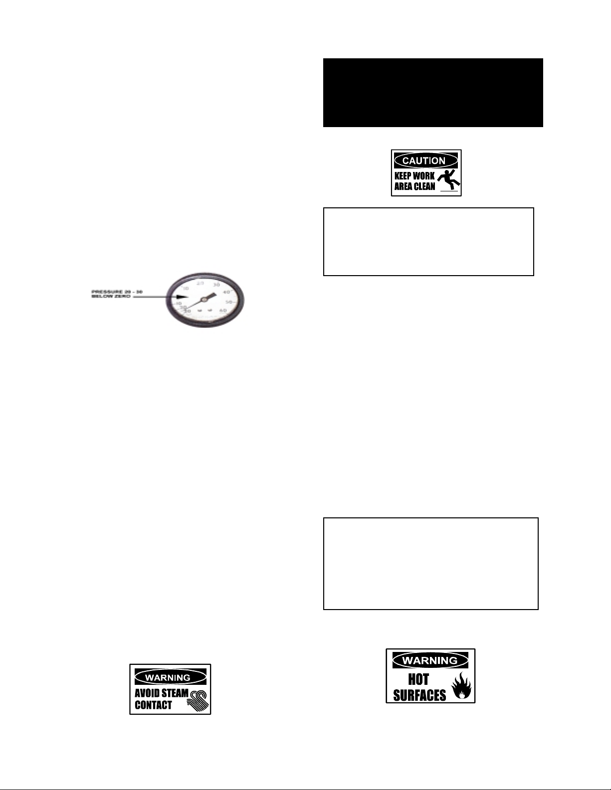
2. W hile the kettle is cold, check the
pressure gauge. If the gauge does not
show 20 to 30 inches of vacuum (that is,
a reading of 20 to 30 below 0), see
“Jacket Vac uum” on page 10.
Be sure that the pressure/vacuum
gauge shows at least 20 inches of
vacuum.
Operation
WARNING
OPEN THE KETTLE LID CAREFULLY TO
AVOID STEAM WHICH MAY ESCAPE.
DIRECT CONTACT COULD RESULT IN
SEVERE BURNS.
CAUTION
KEEP FLOORS IN FRONT OF THE
KETT LE WORK AREA CLEAN AND DRY.
IF SPIL LS OCCUR, CLEAN AT ONCE T O
AVOID SLIPS OR FALLS.
2. Use of Optional Basket Insert
The optional kettl e basket insert set will
assist in cooking water- boiled products
such as eggs, potatoes, v egetables, shell
fish, past a and r ice. The nylon mesh liner
must be used for pr oduc ts smaller t han the
basket mesh size, ( appr oxim ately 1/4” (6
mm). This inc ludes rice and smal l pasta
shapes.
3. Mak e sure t hat the strainer c overs the
draw-off valve outlet at the bottom of the
kettle. This keeps food sol ids from
collecting in t he dr aw-off area.
4. T ur n the thermostat dial to t he desi r ed
setting. The indicator light will confirm
that the kettle is heating. Cycling of the
light on and off shows that the k ettle is
being held at the set temperature. Once
in each cycl e contactors in the
support housing will make a clicking
sound. This is normal.
B. To Transfer Product or Empty Kettle:
1. T he k ettle is emptied by means of its
draw-off valve, by ladling pr oduc t out, or
with the optional tri - basket insert.
Tips For Use.
a) Allow f or displacement of the t hr ee
baskets and product. This may mean
only filling the kettle half way. Test
baskets and product displac ement with
the kettle OFF, and with cold water in
the kettle.
CAUTION
DO NOT OVERFILL THE KETTLE WHEN
COOKING, HOLDING OR CLEANING.
KEEP LIQUIDS AT LEAST 2-3” (5-8 cm)
BELOW THE KETTLE RIM TO ALLOW
CLEARANCE FOR STIRRING, BOILING
AND SAFE PRODUCT TRANSFER.
8
Page 9

WARNING
AVOID ALL DIRECT CONT ACT WIT H HOT
FOOD OR WATER IN THE KETTLE.
DIRECT CONTACT COULD RESULT IN
SEVERE BURNS.
OM-EE
g) Place baskets with food on a stable,
flat surface, inside a solid steamer or
bake pan, to cat c h any r emaining hot
water draining from pr oduc t.
B. To T u rn O ff th e Kettle
b) Load baskets on a lev el, stable work
surface.
c) Lift loaded baskets with both hands. Get
help fr om another person if the basket i s
too heav y for safe handling.
d) Slowly lower produc t into kettle and
securely hook the basket to the “Y”
frame.
e) When r emov ing baskets with cooked
product, lift straight up, ensuring basket
bottoms clear the kett le rim . Wear
protective oven mitts and protect ive
apron.
f) Allow hot water to fully drain fr om
product, before moving basket away
from the kettle. Do not rest baskets on
kettle rim or pour ing lip. If baskets are
too heav y for one individual to lift and
safely move, get help. Remove pr oduct
immediatel y from basket into another
container, being sure to avoid contact
with hot product and hot basket or. . .
1. T ur n the thermostat dial to “OFF.”
2. Before the unit is serviced, or if it will be off
for a week or more:
a. Set the therm ostat to “OFF.”
b. T ur n off electric power t o the unit at t he
circuit breaker or fuse.
Sequence of Operation
The following “action-reacti on” outline i s
provided to help the user under stand how the
equipment works.
When the operator starts up the k ettle by tur ning
the operating thermostat dial f r om “OFF ” to a
desired setting, the therm ostat switch closes.
This lights up the heating indicator light and
causes the contactors to close, allowing power to
flow to heating elements.
When the temperature of the steam jacket
reaches the value corresponding t o the dial
setting, the thermostat switc h opens. This turns
off the heating indicator light and causes the
contactors to open, cutting the power to the
heaters.
As soon as the thermostat senses that the kettle
is cooli ng below the set point, t he thermostat
switch closes, the heating indicator light c omes
on, the contac tors close, and the heaters come
on again. On-off cycl ing continues, keeping the
kettle at the set tem per ature. This i s why the
heating indicator light cycles on and off during
normal operation.
If steam pressure greater than 30 PSI is
generated in the jacket, the safety valve will
open and relieve the excess pressure.
If t he jacket water l evel gets too low, the highlimit control will open and shut off power to the
elements until the kettle cools. This will prevent
the heating elements from overheating.
Setting the operating t her mostat dial to “OFF ”
shuts down all control and heating circ uits.
9
Page 10

OM-EE
Maintenance
NOTICE: Contact Groen or an authorized Groen representative when repairs are required.
1. Periodic Maintenance
A Maintenanc e & S er vic e Log is provided at
the back of this manual with the warranty
infor mation. Each time maintenance is
performed on your Groen kettle, ent er the
date on which the work was done, what was
done, and who did it. Keep this manual on
file and available for operators to use.
Periodic inspection will minimize equipment
down time and increase the effici enc y of
operation. The following points should be
checked:
a. Check the pressure/vacuum gauge
kettle and contact a qualifi ed Groen service
representative.
WARNING
WHEN TESTING, AVOID ANY EXPOSURE
TO THE STEAM BLOWING OUT OF THE
SAFETY VALVE. DIRECT CONTACT
COULD RESULT IN SEVERE BURNS.
2. Jacket V acuum
When the kettle is cold, a posit ive pr essure/
The p r essure gauge should show a vacuum
of 20 to 30 i nches when t he kettle is cold.
every day . The gauge should show a
vacuum of 20 t o 30 inches, when the
kettle is cold. If it does not, see “Jacket
Vacuum” below.
b. Also check the jack et water level every
day. It shoul d be between the marks on
the gauge glass. If the
level is low, see “Jacket
Filling and Water
Treatment” on page 11.
c. Test the safety valve at
least twice each month.
Test the valve with the
kettle operating at 15
psi (105 kPa), by pulling
up the test valve chain
for at least 5 seconds.
Then release the lever
and let the valve snap
shut. If the valve does
not activate, or there is
no evidence of
discharge, or t he valve
leaks, stop using the
Test the safety valve at least twice
monthly.
vacuum gauge reading or a r eading near
zero indicates that there is air in the jacket.
Air in the jacket sl ows kettle heating.
To remove air:
a. Start the unit.(Be sure there is water or
product in the kettle when heating).
b. Mak e sure t hat the elbow of the safety
valve out let is turned so that escaping
steam is di r ec ted toward the floor.
c. When the pressure/vacuum gauge
reaches a positive pressure reading of 5
PSI, release the trapped air and steam
by pulling up or out on the saf ety valve
10
Page 11

lever or ring for about 1 second. Repeat
this step, then let the pull ring or valve
lever snap back into t he c losed position.
OM-EE
f. Any air introduced into the jac k et during
filling must be removed to obtain
efficient heating. See “J ac k et Vacuum”
above.
4. Water Treatment Pro cedure
(1) Obtain water treatment compound and a
pH test kit from y our Groen distributor.
WARNING
STAY AWAY FROM THE STEAM THAT IS
BLOWING OUT OF THE SAFETY VALVE.
THE STEAM CAN CAUSE A SEVERE
BURN.
3. Jacket Filling and Water Treatment
The jacket was charged at the fact or y with
the proper am ount of treated water. You
may need to r estor e this water because it
was lost as steam during venting or by
draining.
a. I f you are repl ac ing water lost as steam,
use distilled water. If you are replacing
treated water that ran out of the jacket,
prepare more treated water as directed
in step 4, “Water Treatment P r oc edur e.”
Do not use tap water.
b. Allow the kettle to cool. Remove the
pipe plug from the jacket fill assembly.
c. Open the gate valve and pour i n the
distilled or treat ed water.
d. Hold the safety valve open to allow air
to escape from the jack et while you
pour in the water. Continue to pour until
the water level rises to a point between
the mark s on the gauge glass.
e. Close the gate v alve and r eplace the
pipe plug.
WARNING
TO AVOID INJURY, READ AND FOLLOW
ALL PRECAUTIONS STATED ON THE
LABEL OF THE WATER TREATMENT
COMPOUND.
(2) Fill a mixing container with the
measured amount of water requi r ed.
(See table). Distilled water is
recommended.
Kettle Model Jacket Capacity
EE-20 3¼ Gallons
EE-30 4½ Gallons
EE-40 5¼ Gallons
EE-60 7¾ Gallons
EE-80 10 Gallons
EE-100 10 Gallons
(3) Hang a str ip of pH test paper on the rim
of the container, wit h about 1 inch of the
strip below the surface of t he water.
(4) M easure t he water treatment c ompound
(One way to do thi s i s to add the
compound from a measuring cup.)
(5) S tir the water continuously, while you
slowly add water treatment com pound,
until the water reaches a pH between
10.5 and 11.5. Judge the pH by
frequently compar ing the test stri p c olor
with the col or c har t provided in the pH
test kit . If you ar e c olor blind have a
person who is not color blind read the
test strip color level.
11
(6) Rec or d the exact amounts of water and
treatment compound used. T hese
amounts m ay be used agai n, if the
same water sources and compound are
used in the future. However, it is best to
check the pH each t ime treated water is
prepared.
Page 12

OM-EE
8.1 Suggested Tools:
a. Cleaner, such as Klenzade HC-10 or
HC-32 from ECOLAB, Inc.
b. Kettle brushes in good condi tion (and a
bottle brush, for the draw-off).
c. Sanitizer such as Klenzade XY-12.
d. F ilm r emov er such as Klenzade LC-30.
8.2 Precautions
Before cleaning, shut off t he k ettle by tur ning
the thermostat dial to “OFF, ” and shut off all
electric power to the unit at a remote switch,
such as the circui t breaker.
WARNING
KEEP WATER AND SOLUTIONS AWAY
FROM CONTROLS AND ELECTRICAL
EQUIPMENT. NEVER SPRAY THE
SUPPORT HOUSING OR ELECTRICAL
CONNECTI ONS.
Cleaning
Use only a sponge, cloth or plastic brush to
clean the ket t le.
CAUTION
MOST CLEANERS ARE HARMFUL TO THE
SKIN, EYES, MUCOUS MEMBRANES, AND
CLOTHING. PRECAUTIONS SHOULD BE
TAKEN. WEAR RUBBER GLOVES,
GOGGLES OR FACE SHIELD, AND
PROTECTIVE CLOTHING. READ THE
WARNINGS AND FOLLOW THE
DIRECTIONS ON THE LABEL OF THE
CLEANER CAREFULLY
8.3 Procedure
a. Clean food-cont ac t surfaces as soon as
possible after use. If the unit is i n
continuous use, thoroughly clean and
sanitize the interi or and exterior at least
once ever y 12 hours.
b. Sc r ape and flush out food residues. Be
careful not to scratch the kettle with
metal implements. Close the dr aw-off.
c. Prepare a hot solution of the detergent/
cleaning compound as instructed by the
supplier. Clean the unit thoroughly. A
cloth moistened with cleaning soluti on
Scrapers or steel wool can harm the kettle
surface.
can be used to clean cont r ols, housings, and
electrical condui ts.
d. Rinse the kettle thoroughly with hot
water, then drai n c ompletely.
e. Disassemble the tangent draw-off valve.
Clean the draw-off port and eac h valve
part with a brush.
CAUTION
DO NOT MIX THE PARTS OF DIFFERENT
DRAW-OFF ASSEMBLIES DURING
WASHING. THE PARTS ARE NOT
ALWAYS INTERCHANGEABLE.
f. Rinse the k ettle and draw-of f valve parts
thoroughly with hot water, then drain
completely.
12
Page 13

g. As part of the daily cleani ng pr ogram,
clean soil ed external and internal
surfaces. Remember to chec k the sides
of the unit and control housing.
h. T o r emov e stuc k materi als, use a brush,
sponge, cloth, plastic or rubber scraper ,
or plastic wool with the cleani ng sol ution.
To reduce effort r equired in washing, let
the detergent sol ution sit i n the kettle
and soak into the resi due. Do NOT use
abrasiv e materi als or metal tools that
might scr atch the surface. Scratches
make the surface harder to clean and
provide places for bacteria t o gr ow.
Do NOT use steel wool, whic h may
leave particles in the surfac e and c ause
event ual corrosion and pi tting.
i. The outside of the uni t may be polished
with a stainl ess steel cleaner such as
“Zepper” from Zep M anufacturing Co. Or
Groen Degreaser. (Par t Number
140830)
OM-EE
CAUTION
NEVER LEAVE A CHLORINE SANITIZER
IN CONTACT WITH STAINLESS STEEL
SURFACES LONGER THAN 30 MINUTES.
LONGER CONTACT CAN CAUSE
STAINING AND CORRO S ION.
k. It is recommended that each piece of
equipment be sanitized j ust before use.
l. If there is difficulty r emov ing miner al
deposits or a film left by har d water or
food residues, c lean the kettle
thoroughly and then use a deliming
agent, like Groen Delimer/Descaler (Part
Number 140513) or Lime-A-Way® from
Ecolab, in accordance with t he
manuf ac turer’s directions. Rinse and
drain the uni t before further use.
m. If cleaning problems persist, contac t
your cleaning product representative for
assistance.
j. When equipment needs to be sanitized,
use a solution equivalent to one that
supplies 200 parts per m illion available
chlorine. Obtain advic e on sani tizing
agents from your supplier of saniti z ing
products. Following the suppli er ’s
instructions, apply the agent after the
unit has been cleaned and dr ained.
Rinse off the saniti z er thoroughly.
Troubleshooting
Your Groen ket tle is designed to operate smoothly and efficiently if pr oper ly maintained. However, the
following is a li st of checks to make in the event of a problem. Wiring diagr ams are furnished inside the
<
servi ce panel and in this manual. If an item on the list is followed by
a quali f ied service represent at ive.
USE OF ANY REPLACEMENT PARTS OTHER THAN THOSE SUPPLIED BY GROEN OR THEIR
AUTHORIZE D DISTRIBUTORS CAN CAUSE INJURY TO THE O P E RATOR AND DAMAGE TO T HE
EQUIPMENT AND WILL VOID ALL WARRANTIES.
SYMPT OM WHO WHAT TO CHE CK
<<<<indicates items which must be performed by an authorized technician.
Kettle will not heat, and heating indi c ator
will not come on.
User a. E lectric power supply to the unit .
b. W ater level in jacket.
c. Contr ol circuit fuses in t he c ontrol console.
REPLACE BLOWN FUSES ONLY WITH A
FUSE OF THE SAME AMP RATING. a
HIGHER RATED FUSE WILL NOT PROTECT
THE UNIT O R THE BUILDING.
Auth
Service
Rep Only
d. For loose or broken wires.
f. Oper ation of vari able thermostat. <
g. Low water cutout switch. <
h. Wat er probe.<
i. That high limit pressure switch is closed. <
<, the work should be done by
<<
<
13
Page 14

OM-EE
Troubleshooting, Continued
SYMPT OM WHO WHAT TO CHE CK
<<<<indicates items which must be performed by an authorized technician.
Kettle will not heat, but heating indicator
comes on.
Kettle c ontinues heating after it reaches
the desired temperature
Kettle st ops heating before it reaches the
desired tem per ature.
Kettle heats slowly User a. For air i n the jacket. S ee “ J ac k et Vacuum” in
Safety valve pops. User a. For air in the jacket . See “Jacket Vac uum” in
Safety valve leak s a sm all amount of
steam when the kett le is operating.
User a. For air in the jacket. See “Jacket Vac uum” in
the Maintenance section of this manual.
Auth
Service
Rep Only
User a. Thermostat dial setti ng.
Auth
Service
Rep Only
User a. Thermostat dial setti ng.
Auth
Service
Rep Only
Auth
Service
Rep Only
Auth
Service
Rep Only
User a. For contam ination that prevents seating of
Auth
Service
Rep Only
b. Contactor.
c. Heater elements with ohmmeter for ground
short or open element. If element is defect ive,
call G roen.
b. Thermostat c ircuit for short.
c. Ther mostat cal ibration.
d. Thermostat oper ation. The t her mostat should
click when the dial is rot ated above and below
the setting for the temperature of the kettle.
e. Contactor, to determine whether it is energized
or stuck.
b. Jacket water level .
c. Ther mostat cal ibration.
d. Thermostat oper ation. The t her mostat should
click when the dial is rot ated above and below
the setting for the temperature of the kettle.
e. Pressure limit switch.<
the “Maintenance” section of this manual.
b. Heater elem ents with ohmm eter for ground
short or open element. If an element is
defective, call G roen.
c. Voltage of main power source. <
the “Maintenance” section of this manual.
b. Whet her k ettle was being heated empty when
valve popped.
c. Pressure limit switch.
d. Thermostat oper ation. Thermostat should
click when the dial is rot ated above and below
the setting for the temperature of the kettle.
e. Safety valve. I f the valve pops at pressures
below 48 PSI, replace it.
f. Contac tor, to determine whether i t is de-
energized.
valv e. With full pressure in the jacket, pull the
chain all the way briefly to bl ow the valve
clean, then let it snap back to seat the v alve.
b. Safety valve for defect s. Replace any
defective valve with an identical valve.
<
<
<
<
<
<
<
<
<
<
<
<
<
14
Page 15

Parts List
To order parts , contact your Groen Certified Serv ic e A genc y . Supply the model designat ion, part description, part number, quant ity, and, wher e applicable,
voltage and phase.
15
Page 16

OM-EE
Parts List
Key Descriptio n Part No. Key Descriptio n Part No.
1 ¼” - 20 N.C. Cap Nut 005471 29 Hex. Nut (wit h A ssem bly 004071)
2 Handle (40 Gal. & smaller kettles) 047714 30 Water Gauge Glass 008742
3 Knob ( Friction) 012691 31 Warrick Elec trode 074665
4 Spac er 012733 32 Doubel Heater Element 230/460V - 008801
5 F use Hol der 002944 4000W
6 Ac tuator Cover (60 Gal. ) 012520 33 Double Heater Element 230/460V - 008802
7 Ac tuator Cover (80 Gal. ) 012521 2000W
8 ½” - 20 N.F.x 1" Hex Cap Screw 002212 34 Bullet Foot A ssembly 002479
9 ½” B r ass Washer 001213 35 Snap-in Indic ator Light 125 V 002986
10 ½”-20 N.F. x 5/16" Thick Jam Nut 002218 36 Snap-in Indicator Light 250 V 016028
11 30 Lb. Safety V alve 097009 37 Warrick Relay 230V 010410
12 Pressure Gauge 099156 38 Tolerance Ring 012692
13 Fuse - 3 Amp, 208 & 240 V 002945 39 Warrick Relay 115V & 480V 010412
14 Contactor (SEE DRAW ING NOTE) 40 Removable Strainer 9" Di a ¼” holes 009007
15 Water Fill Assembly 097010 Removable Strainer 9" Dia ¼” holes 009044
16 Thermostat 012313 2" Tangent Dr aw-Off
17 Pressure Limit Control 096963 41 Remov able Strainer 9" Dia
18 Thermostat Knob 012314 Removable St r ainer 9" Dia
19 1½” Draw-Off Valve, Complete 009000 2" Tangent Draw-Off
20 2" Draw-Off Valve, Complete 009046 42 Remov able Strainer 9" Dia no holes 009057
21 Valv e S tem 009048 Removable St rainer 9" Dia no holes 013783
22 Rubber “O” Ring 009034 2" Tangent Draw-Off
23 Sanitary Hex. Nut #13H 008911 43 Single Heater Element 240V-
4000W
24 Valv e Handle 009029 44 S ingle Heater Element 208V-
3600W
25 Wi ng Nut 009028 45 Single Heater E lement 240V-
2000W
c” holes 009040
c” holes 013785
008851
008852
008853
26 ½”Gauge Glass Connector A ssy. 004071 46 Single Heater Elem ent 240V-
2000W
27 Rubber Gauge Glass Gasket 008917 (240V-2500W)
28 Washer (wit h A ssembly 004071) Delimer/Descal er ( 8 pac k) 140513
Degreaser Spray 140830
Note: To order a new contactor, specify the part number on the old contactor.
16
008854
Page 17

Electrical Schematics
17
Page 18

OM-EE
EE-40 208/230/240 V,1PH
18
Page 19

EE-40 208/230/240 V,3PH
EE-40 480 V, 3PH
19
Page 20

OM-EE
20
Page 21

References
KLENZADE SALES CENTER ECOLAB. Inc.
370 Wabasha
St. Paul , Minnesota 55102
800/352-5326 or 612/293-2233
NATIONAL FIRE PROTECTION ASSOCIATION
60 Battery March Park
Quincy, Massachusetts 02269
NFPA/70 - The Nati onal Electr ical Code
ECONOMICS LABORATORY, INC.
St. Paul , Minnesota 55102
NATIONAL S A NITATIO N FOUNDATION
3475 Plym outh Rd.
Ann Arbor, Michigan 48106
UNDERW RITERS LABORA TORIES, I NC.
333 Pfi ngsten Road
Northbrook, Illi nois 60062
ZEP MANUFA CTURING CO.
1310-T Seaboard Industr ial Blvd.
Atlanta, Georgia 30318
21
Page 22

OM-EE
Service Log
Model No. _______________________________ Purchased From _________________________
Serial No. _______________________________ Locat ion ________________________________
Date Purchased __________________________ Date Installed ___________________________
Purchase Order No. ______________________ For Service Call __________________________
Date Service Performed Performed By
22
Page 23

LIMITED WARRANTY TO
COMMERCIAL PURCHASERS*
(U.S. & Canadian Sales Only.)
Groen warrants to ori ginal com mer c ial purc haser/users that f oodservice equi pm ent m anuf act ured by G roen
(“Groen Equi pm ent” ) (ot her than CapK ol d foodservice equipm ent ) shall be f ree f r om def ect s in m ater i al and
workmanship for (12) twelve months from the date of installation or fifteen (15) months from date of
shipment f rom Groen, whichev er date f ir st oc curs (the “W ar ranty Peri od”), in accordanc e with the f oll owing
terms and conditions:
I. This warranty i s limit ed to replacement parts and relat ed l abor for Groen Equipment locat ed at its
original place of installation in the United States and Canada.
II. Damage to Gr oen Equi pm ent t hat oc curs duri ng shipm ent m ust be report ed to t he carri er, and i s not
cover ed under thi s warranty. The repor ti ng of any dam age dur ing shi pm ent i s the sole r esponsibility
of the commerc ial purchaser/user of such Groen Equipment.
TM
III. For Groen Convection Combo
HyPlus
TM
Pressureless Steamers, G roen f ur ther warrant s to the ori gi nal com m erc ial purc haser/use r s
of such Groen E quipm ent that the at m ospheric steam generat ors or boil er s cont ained i n such Gr oen
Equipment sha ll b e f ree from defects in m at eri al and workm anshi p f or t wenty-f our (24) m ont hs fr om
the date of installati on or twenty-seven ( 27) months from date of shipm ent from Groen, whichev er
date first occurs, provided that: (a) the original purchaser/user shall have also purchased and
installed a Groen PureSteem Water Treatment System
Convection Combo
TM
Steamer-Oven, HyPerSteamTM Convection Steamer or HyPlusTM Pressureless
Steamer on or befor e the date such Groen E quipm ent was inst al l ed , (b) the or iginal purchaser/user
has continuously used suchWater Treatment S y stem in connection with such Gr oen E quipment from
the date of installation, and (c) the comm ercial purchaser/user shall hav e mai ntai ned such Wat er
Treatment System in accordance with the maintenance and filter cartridge replacement
recomm endat ions of G roen, and ot herwise m ai ntai ned such Oven or Steam er in ac cordanc e with al l
other operational and maintenance recom mendations of Groen.
Steamer-Ovens, HyPerSteamTM Convection Steamers and
TM
for use in connection with such Groen
IV. G roen further warrants to the ori gina l co mm ercial purchaser/users of G roen Convection Com bo
Steamer-Ovens that the electronic relay and control board contained in such Groen Convection
Combo
TM
St eam er -O v en shal l be free f rom def ect s in m at eri al and workmanshi p f or t wenty-f our (24)
TM
months f rom t he date of i nstal l ati on or t wenty-sev en ( 27) m onths f rom date of shipm ent f rom G roen,
whichever date first occurs.
V. During the Warranty Period, Groen, directly or through its authorized serv ice representative, will
either repair or replace, at Groen’s sole election, any Groen Equipment determined by Groen to
hav e a defect in material or workmanship. As to any such warranty serv ice during the W arrant y
Period, Groen will be responsible for related reasonable labor and portal to portal transportation
expenses (time & mi leage) incurred within the United States and Canada.
VI. This warranty does not cover boiler main tenance, cali bration, periodi c adjustments as specifi ed in
operating instructions or manuals, consumable parts (such as scraper blades, gaskets, packing,
etc.), and labor cost s inc urred f or rem oval of adj acent equi pm ent or obj ec ts to gai n access to Gr oen
Equipment . This warranty does not c over def ects caused by i m proper i nstallati on, abuse, careless
operation , or im proper m aint enance of G roen Equi pment. This warranty does not cov er damage t o
Groen Equipment caused by poor water quality or improper boiler maintenance.
23
Page 24

OM-EE
VII. THI S WARRANTY IS EXCLUSIVE AND IS IN LIEU OF ALL OTHER WARRANTIES,
EXPRESSED OR IMPLIED, INCLUDING ANY IMPLIED WARRANTY OF MERCHANTABILITY OR
FITNESS FOR A PARTICULAR PURPOSE, EACH OF WHICH IS HEREBY EXPRESSLY
DISCLAIMED. THE REMEDIES DESCRIBED ABOVE ARE EXCLUSIVE AND IN NO EVENT
SHALL GROEN BE LIABLE FOR SPECIAL, CONSEQUENTIAL, OR INCIDENTAL DAMAGES FOR
THE BREACH OR DE LA Y IN PERFORMANCE OF THIS WARRANTY .
VIII. Groen Equipment is for commerci al use only. If sold as a component of another (O .E.M.)
manuf ac turer’s equipment, or if used as a consumer product, such Equipment is sold AS IS and
without any warranty.
* (Covers all Groen Equipment (other than CapKold foodservice equipm ent) ordered after
September 11, 2001).
24
Page 25

1055 Mendell Davis Drive
Jackson, Mississippi 39272
Telephone 601 373-3903
FAX 601 373-9587
OM-EE (Revised 2/03)
Part Number 121019 Rev B
 Loading...