

Groen CNGB-3-24 Installation Manual
OPERATOR MANUAL
IMPORTANT INFORMATION, KEEP FOR OPERATOR
This manual provides information for:
MODEL NGB/3E
& CNGB/3-24
STEAM BOILERS
· Gas Heat
· 200,000 BTU/hr Firing Rate
· 3.7 Effective Boiler Horsepower
READ, UNDERSTAND AND FOLLOW THE INSTRUCTIONS AND
WARNINGS CONTAINED IN THIS MANUAL.
.ECNEREFER ERUTUF ROF DENIATER EB TSUM LAUNAM SIHT
WARNING / FOR YOUR SAFETY
and liquids in the vicinity of this or any other appliance.
POST IN A PROMINENT LOCATION
Instructions to be followed in the event user smells
gas. This information shall be obtained by consulting
your local gas supplier. As a minimum, turn off the gas
and call your gas company and your authorized service
agent. Evacuate all personnel from the area.
WARNING
Improper installation, adjustment, alteration, service
or maintenance can cause property damage, injury or
death. Read the installation, operating and maintenance
instructions thoroughly before installing or servicing this
equipment.
NOTIFY CARRIER OF DAMAGE AT ONCE
It is the responsibility of the consignee to inspect the container upon receipt of
same and to determine the possibility of any damage, including concealed damage. Unified Brands suggests that if you are suspicious of damage to make a
notation on the delivery receipt. It will be the responsibility of the consignee to file
a claim with the carrier. We recommend that you do so at once.
Manufacture Service/Questions 888-994-7636.
Information contained in this document is known to be current and accurate at the time
of printing/creation. Unified Brands recommends referencing our product line websites,
unifiedbrands.net, for the most updated product information and specifications.
PART NUMBER 121003 REV D (07/14)
1055 Mendell Davis Drive
Jackson, MS 39272
888-994-7636, fax 888-864-7636
unifiedbrands.net

IMPORTANT - READ FIRST - IMPORTANT
WARNING: THE UNIT MUST BE INSTALLED BY PERSONNEL QUALIFIED TO WORK WITH GAS, ELECTRICITY AND
PLUMBING. IMPROPER INSTALLATION CAN CAUSE INJURY TO PERSONNEL AND/OR DAMAGE TO
THE EQUIPMENT. THE UNIT MUST BE INSTALLED IN ACCORDANCE WITH APPLICABLE CODES.
NOTICE: LEVEL THE UNIT BEFORE USE. IT MAY BE PITCHED SLIGHTLY TO THE REAR.
CAUTION: AN ELECTRICAL GROUND IS REQUIRED.
CAUTION: DO NOT LOCATE THE BOILER CABINET DIRECTLY OVER A FLOOR DRAIN OR FLOOR SINK. HUMIDITY
OR WATER FROM A DRAIN WILL DAMAGE ELECTRICAL PARTS OF THE UNIT.
WARNING: TO AVOID DAMAGE OR INJURY, FOLLOW THE WIRING DIAGRAM EXACTLY WHEN CONNECTING A
UNIT.
CAUTION: DO NOT USE PLASTIC PIPE. DRAIN MUST BE RATED FOR STEAM AND BOILING WATER.
WARNING: DO NOT CONNECT THE DRAIN DIRECTLY TO A BUILDING DRAIN.
WARNING: BLOCKING THE DRAIN MAY BE HAZARDOUS.
IMPORTANT: IMPROPER DRAIN CONNECTION WILL VOID WARRANTY.
WARNING: ALLOW COOKING CHAMBERS TO COOL BEFORE CLEANING.
WARNING: CAREFULLY READ THE WARNINGS AND FOLLOW THE DIRECTIONS ON THE LABEL OF EACH
CLEANING AGENT. USE SAFETY GLASSES AND RUBBER GLOVES AS RECOMMENDED BY DELIMING
AGENT MANUFACTURER.
WARNING: DO NOT MIX DE-LIMING AGENTS (ACID) AND DE-GREASERS (ALKALI) IN THE STEAM GENERATOR
OR ON THE COOKING CHAMBER WALLS.
NOTICE: DO NOT USE A CLEANING OR DE-LIMING AGENT THAT CONTAINS ANY SULFAMIC ACID OR
ANY CHLORIDE, INCLUDING HYDROCHLORIC ACID (HCL). IF THE CHLORIDE CONTENT OF ANY
PRODUCT IS UNCLEAR, CONSULT THE MANUFACTURER.
NOTICE: DO NOT USE A DE-GREASER THAT CONTAINS POTASSIUM HYDROXIDE OR SODIUM HYDROXIDE OR
THAT IS HIGHLY ALKALINE.
WARNING: USE OF ANY REPLACEMENT PARTS OTHER THAN THOSE SUPPLIED BY GROEN OR THEIR
AUTHORIZED DISTRIBUTOR VOIDS ALL WARRANTIES AND CAN CAUSE BODILY INJURY TO THE
OPERATOR AND DAMAGE THE EQUIPMENT. SERVICE PERFORMED BY OTHER THAN FACTORYAUTHORIZED PERSONNEL WILL VOID ALL WARRANTIES.
WARNING: HIGH VOLTAGE EXISTS INSIDE CONTROL COMPARTMENTS. DISCONNECT POWER SOURCE BEFORE
SERVICING. FAILURE TO DO SO CAN RESULT IN SERIOUS INJURY OR DEATH.
WARNING: DO NOT EXPOSE SKIN TO ESCAPING STEAM. SEVERE BURNS CAN RESULT.
CAUTION: MAKING ANY ELECTRICAL OR MECHANICAL CHANGE IN THE UNIT WITHOUT PRIOR WRITTEN
APPROVAL FROM GROEN ENGINEERING WILL VOID ALL WARRANTIES.
WARNING: ALL POTENTIAL USERS OF THE EQUIPMENT SHOULD BE TRAINED IN SAFE AND CORRECT
OPERATING PROCEDURES.
WARNING: DO NOT OPERATE THE UNIT UNLESS ALL REMOVABLE PANELS (RIGHT, LEFT, FRONT AND REAR)
HAVE BEEN PROPERLY INSTALLED.
2 OM-NGB/3

Table of Contents
Important Operator Warnings ...................................................... page 2
References..................................................................................... page 3
Equipment Description.................................................................. page 4
Water Quality and Treatment ......................................................... page 5
Installation .................................................................................. page 6-7
Initial Start-Up................................................................................ page 8
Operation ...................................................................................... page 9
Sequence of Operation ................................................................ page 10
Cleaning.................................................................................. page 11-12
Maintenance................................................................................. page 13
Troubleshooting...................................................................... page 14-15
Electrical Schematic .................................................................... page 19
Service Log ................................................................................. page 20
References
NATIONAL FIRE PROTECTION ASSOCIATION
60 Batterymarch Park
Quincy, Massachusetts 02269
NFPA/70 The National Electrical Code
NFPA/54 Installation of Gas Appliances & Piping
NFPA/96 Ventilating Hoods
NSF INTERNATIONAL
789 N. Dixboro Rd.
P.O. Box 130140
Ann Arbor, Michigan 48113
CSA INTERNATIONAL
8501 Ease Pleasant Valley Road
Cleveland, Ohio 44131
AMERICAN NATIONAL STANDARDS INSTITUTE
1403 Broadway, New York, New York 10018
Z21.30 Installation of Gas Appliances & Piping
Z223.1 (latest edition) National Fuel Gas Code
OM-NGB/3 3
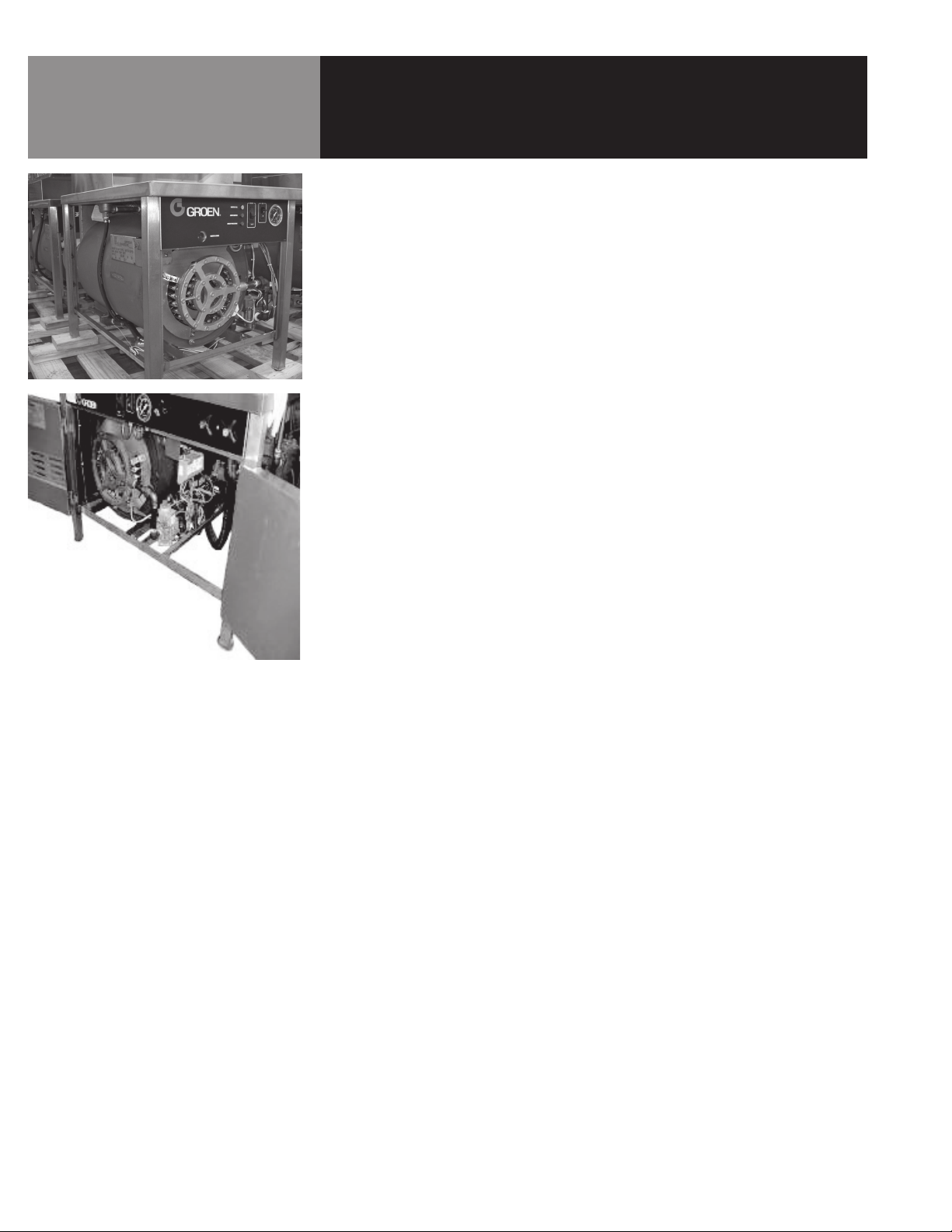
Equipment Description
Groen NGB/3E and CNGB/3-24 steam boilers generate low pressure steam for use
with HyPlus cabinet mounted steamers and steam jacketed kettles. Both models
use a spark ignition system. The boiler is housed in a stainless steel cabinet. Various
combinations of steam-operated kettles and steamers can be mounted on the top.
The boiler is small enough to fit in a 24-1/8” wide by 34-3/16” deep by 29-3/16” tall
(maximum) cabinet.
The boiler is constructed of 1/4” thick steel, which is certified by the American Society
of Mechanical Engineers (ASME) for pressure vessels. All welds are hydrostatically
tested. The boiler is also equipped with required instruments, fittings, and
controls per CSD-1 (Controls and Safety Devices for automatically fired boilers).
Heat transfer fins inside the combustion chamber add to the unit’s high efficiency.
Both units are rated as 60% efficient or better, with a firing rate of 200,000 BTU per
hour using natural or propane gas. Energy output is 120,000 BTU per hour, with an
effective boiler horsepower of 3.7.
4 OM-NGB/3

Water Quality & Treatment
REDUCE SCALE PROBLEMS BY USING
AND MAINTAINING A WATER SOFTENER
FOR YOUR STEAMER!
It is essential to supply the steam generator with water that will not form scale or cause
corrosion. Even though the steam generator is engineered to minimize scale formation
and the effects of corrosion, their development depends on the quality of your water
and the number of hours per day you operate the equipment.
Most water supplies are full of minerals and chemicals which are not suitable for use in
a steam generator.
Water quality varies from state to state and city to city. It is necessary that you know
and understand the quality of the water you are using. Your water utility can tell you
about the minerals and chemicals in your water. The water going to the steam generator should be within these guidelines
Water Pressure 30-60 psi
PH 7 to 9
Hardness less than 60 ppm
TDS 30 to 60 ppm
Chlorine and Chloramine less than 0.1 ppm
Total Chloride less than 30 ppm
Silica less than 12 ppm
Undissolved Solids less than 5 microns
1. Do not rely on unproven water treatments which are sold for scale prevention or
scale removal. They don’t always work. The best way to prevent scale is to supply
the purest possible water (30 - 60 ppm TDS).
2. If your water contains scale-forming minerals, as most water does, use a
well-maintained water softener. Whether an exchangeable softener cartridge or a
regenerating system is chosen, a regular exchange schedule is essential.
3. Installing a water meter between the softener and the steamer will provide an
accurate gauge of water use, and will help determine when to exchange cartridges
or regenerate the softener. Using a water softener will provide longer generator life,
higher steam capacity, and reduce maintenance requirements.
4. If you notice a slowdown in steam production, have the unit checked for scale
build-up. Heavy scale reduces the unit’s ability to boil water and can even cause
heating elements in the steam generator to overheat and burn out.
OM-NGB/3 5

Installation
WARNING
MAKING ANY ELECTRICAL OR MECHANICAL
CHANGE IN THE UNIT WITHOUT PRIOR
GROEN APPROVAL WILL VOID ALL
WARRANTIES.
WARNING
THE UNIT MUST BE INSTALLED BY
PERSONNEL WHO ARE QUALIFIED TO WORK
WITH GAS, ELECTRICITY AND PLUMBING.
IMPROPER INSTALLATION CAN CAUSE
INJURY TO PERSONNEL AND/OR DAMAGE
TO THE EQUIPMENT. THE UNIT MUST
BE INSTALLED IN ACCORDANCE WITH
APPLICABLE CODES. THE UNIT MUST BE
INSTALLED BY A LICENSED PLUMBER OR
GAS FITTER WHEN INSTALLED WITHIN THE
COMMONWEALTH OF MASSACHUSETTS.
WHEN THE UNIT IS RECEIVED, IMMEDIATELY INSPECT IT FOR EXTERNAL OR INTERNAL
DAMAGE. REPORT ANY DAMAGE TO THE FREIGHT CARRIER.
After inspection, keep the unit in its shipping container until it is installed. It can be
installed on combustible and non-combustible floors. Minimum clearances are:
Right Side 2 inches
Left Side 4 inches
Rear 6 inches
In order to service the unit properly, access with at least 24 inches clearance is
needed on the right side.
Install the unit in a well-vented room so that there is an adequate air supply. Since
products of combustion come out of its flue, the appliance must be located under a
ventilation hood. Do not directly vent the flue.
Level the unit front to rear and left to right by adjusting its legs. Levelness may be
checked by using a spirit level on top of the cabinet.
A free flow of air around the boiler promotes efficient operation. Items which might
restrict air flow must be removed. After installation, do not obstruct the flue, or any
front, side, rear or top vents. Similarly, keep the area directly around the appliance
clear of combustible material.
Installation must conform with local codes, or in the absence of local codes, with the
National Fuel Gas Code, ANSI Z223.1 (latest edition, including the following paragraph:
“The unit and its individual shut-off valve must be disconnected from the gas supply
piping system during any pressure testing of that system at test pressures in excess
of 1⁄2 PSI (3.45 kPA). The unit must be isolated from the gas piping system by closing
its individual manual shut-off valve during any pressure testing of the gas supply
piping system at test pressures equal to or less than 1⁄2 PSI (3.45 kPA).”
1. Gas Supply Connection
a. Connection to the gas supply can be completed with 1/2” NPT pipe
or approved equivalent. Although this is the diameter for immediate
connection to the unit, gas supply piping must be large enough to
provide volumes and pressure sufficient for 200,000 BTU per hour.
Supply pressure must be at least 5.0” W.C. (14.0” W.C. maximum) for
natural gas or 11.0 W.C. (14.0” W.C. maximum) for propane.
b. In Canada, the installation must conform to the Canada Gas Code, CAN
1-B149 (Installation Codes for Gas Burning Appliances and Equipment),
and/or local codes.
c. After the unit has been connected to the gas supply, check piping joints
for leaks. Do NOT use flame to check for leaks. A thick soap solution or
other suitable leak detector should be used.
2. Electrical Supply Connection
a. The maximum electrical load is 4 AMP. You must provide 115 Volt
Alternating Current, 60 Hz, 1PH, 15 AMP service. Local codes and/or the
National Electrical Code should be followed (ANSI/NFPA-70-1987 - or
latest edition). AN ELECTRICAL GROUND IS REQUIRED.
6 OM-NGB/3
CAUTION
DO NOT LOCATE THE BOILER CABINET
DIRECTLY OVER A FLOOR DRAIN OR FLOOR
SINK. HUMIDITY OR WATER FROM WILL
DAMAGE ELECTRICAL.
IMPORTANT
IMPROPER DRAIN CONNECTION
WILL VOID WARRANTY.
Installation
b. Copies of the electrical schematic are located in the electrical enclosure
on the equipment and in this manual. In Canada, electrical service must
comply with the Canadian Electrical Code, CSA C22.1, Part 1, and/or
local codes.
3. Water Connection
a. Cold water is supplied via a 1/2” NPT pipe connection at the rear of the
unit. A check valve (back siphonage device) must be installed in accord
with local plumbing codes.
b. Water pressure should be between 30 and 60 PSI. If it is over 60 PSI,
a pressure regulator is required. A strainer screen at the connection is
also recommended, to trap any debris before it can enter the system.
c. The boiler uses a maximum of 12.9 gallons of water per hour. Piping
should be sized to handle total water consumption.
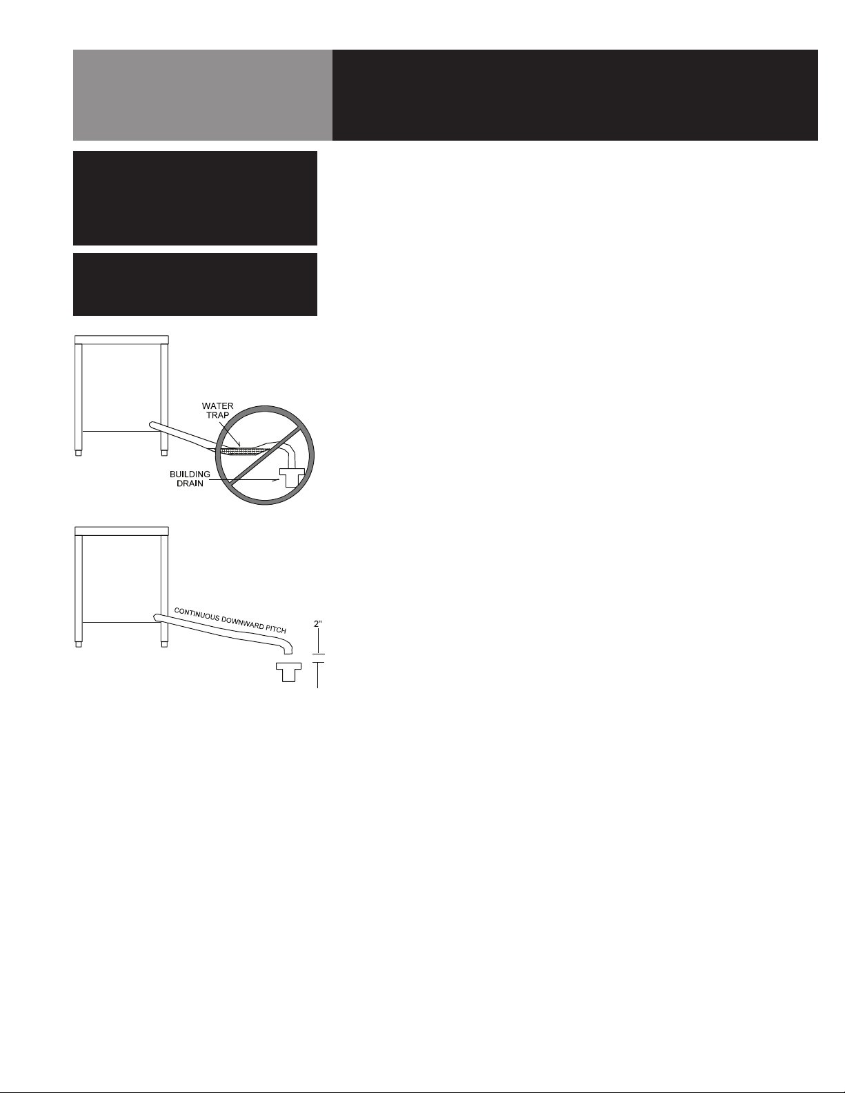
4. Drain Connection
a. The drain connection is made at the rear of the unit with 1 - 1/4” NPT
pipe. DO NOT USE PLASTIC PIPE. DRAIN PIPING MUST WITHSTAND
STEAM AND BOILING WATER. Extend the drain piping to a nearby
floor drain. Piping of 1 - 1/4” NPT (or 1 - 1/2” NPT) is acceptable for
distances of six feet or less. If the distance to the drain is further than
six feet, use 2” NPT piping.
Leave a two-inch air gap between the
hose and the building drain, and don’t
allow water traps in the line.
b. The drain line must be installed with a constant downward pitch. Do
not permit any water traps in the line. DO NOT CONNECT THE LINE
DIRECTLY TO ANY BUILDING DRAIN. A vertical air gap of at least two
inches must be maintained between the drain line and the building drain
unless otherwise specified by local plumbing codes.
OM-NGB/3 7
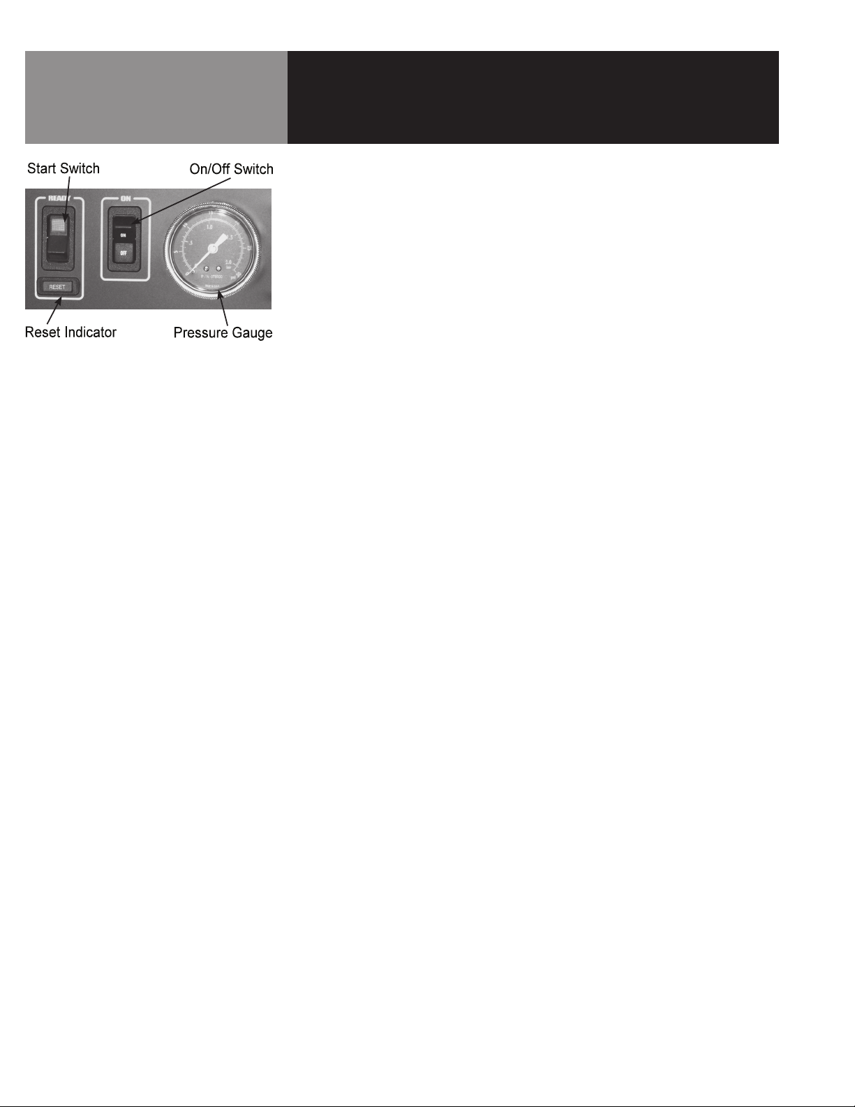
Operating Controls are located on the
front of the cabinet base unit.
Initial Start-Up
After the unit has been installed, test it to ensure that it is operating properly.
1. Remove literature and packing material from the interior and exterior of the unit.
2. Make certain the water supply is turned on.
3. Turn on electrical power to the unit.
4. Make sure the gas supply line is open, and turn on the gas valve.
Turn the knob on the gas valve to the “ON” position.
NOTE: The “trial for ignition” period is approximately 90 seconds after the on/off
switch is turned to the “ON” position. (Refer to the Control Panel illustration in
the Operation Section).
During initial start-up several trials may be necessary to remove air from the gas
piping. Subsequent start-ups should only need about five seconds for the pilot to
light. If the pilot burner does not light within the trial period, the ignition system
will automatically stop gas flow to the pilot burner, and terminate the ignition
trial. If this happens, turn the switch to “OFF” and then “ON” again, to repeat the
trial for ignition.
5. Turn the on/off switch on the cabinet front panel to the “ON” position:
• The amber light in the switch will come on
• The boiler drain valve will close
• The unit will fill with water
When the water level reaches the “mid” probe, the red RESET light will come on.
Push the start switch.
• The green light in the switch will come on
• The RESET light will go out
• The main burner will light
When the water level reaches the “hi” probe, the water supply to the boiler will
shut off.
6. After about 15 minutes, the pressure on the gauge will rise. When the pressure
reaches 9- 1/2 PSI, the main burner will turn off. Thereafter, as pressure
decreases, the burner will automatically re-light to maintain the 9-1/2 PSI level.
The pilot burner should stay lit, even though the main burner cycles on and off.
7. To shut the unit down, turn the on/off switch to OFF. When it has cooled to
approximately 170ºF, the boiler will automatically drain.
The pilot is off when the on/off switch is OFF.
If the boiler functions as described above, it is ready for use. If it does not, contact
your authorized Groen Service Agent.
8 OM-NGB/3
 Loading...