

Page 1
CKPF/3 MOBILE PUMP/FILL STATION
IMPORTANT INFORMATION! * KEEP FOR OPERATOR * IMPORTANT INFORMATION!
OPERATOR’S MANUAL OM-CKPF/3
Page 2

CKPF/3 MOBILE PUMP/FILL STATION
Model CKPF/3
Table of Contents
Description
Operator Warnings 3-6
Equipment Description 7-8
Installation and Start-up Instructions 9-10
Operation 11-14
Equipment Cleaning and Sanitization Procedures 15-16
Maintenance Schedule 17
Troubleshooting 18
Suggested Spare Parts List 19-20
Schematic 21
Service Log 22
Limited Warranty 23
Operator’s Manual page 2 OM-CKPF/3
Rev. 1 2-6-03
Page
Page 3

CKPF/3 MOBILE PUMP/FILL STATION
IMPORTANT! — READ FIRST — IMPORTANT!
Operator Warnings
WARNING: Do NOT attempt to install, set up or operate this machine BEFORE you have
read and understand this manual and ALL accompanying manuals. KEEP ALL MANUALS
FOR FUTURE REFERENCE.
WARNING: Be sure operators read, understand and follow the operating instructions,
cautions and safety instructions in this manual. Additional manuals are supplied with the
CKPF/3 Mobile Pump/Fill Station. Be sure operators read, understand and follow ALL
operating instructions, cautions and safety instructions in these additional manuals. Any
potential user of the equipment MUST be trained in safe and correct operating
procedures.
WARNING: When using this machine, ALL operating instructions, safety instructions and
precautions MUST be followed and strictly adhered to.
WARNING: This machine is intended for use in the commercial transfer and packaging of
food products, per the instructions contained in this manual. Other use could result in
personal injury or damage to the equipment and will void ALL warranties.
WARNING: AVOID ALL direct contact with HOT equipment surfaces. Direct skin contact
could result in severe burns.
WARNING: AVOID ALL direct contact with HOT food. Direct skin contact could result in
severe burns.
WARNING: Use of any replacement parts other than those supplied by Groen or its
authorized distributors voids ALL warranties and may cause bodily injury or equipment
damage. Service performed by other than authorized personnel will void ALL warranties.
WARNING: Turn the electric power OFF and unplug the unit BEFORE working on internal
components.
WARNING: Turn the electric power OFF and unplug the unit BEFORE performing any
cleaning operation.
WARNING: Be careful to AVOID contact with cleaning products in accordance with the
supplier and manufacturer recommendations. Many cleaners are harmful to the skin, eyes,
mucous membranes and clothing. Read the warnings and follow directions on the cleaner
label.
CAUTION: NEVER leave a chlorine sanitizer in contact with stainless steel for longer than
30 minutes. Longer contact can cause corrosion.
WARNING: Do NOT use a fuse with a higher AMP rating than the rating specified for that
circuit.
Operator’s Manual page 3 OM-CKPF/3
Rev. 1 2-6-03
Page 4
CKPF/3 MOBILE PUMP/FILL STATION
IMPORTANT! — READ FIRST — IMPORTANT!
Operator Warnings Continued
Grove
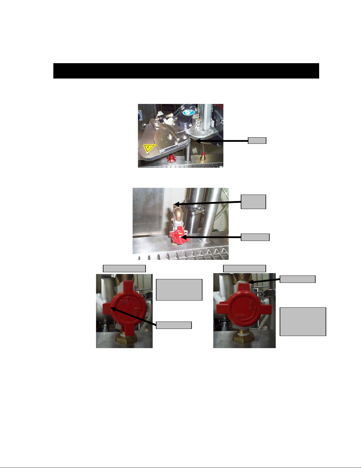
WARNING: NEVER place fingers or other body parts in the Tipper Tie clipper groove where
the clips seal the casings.
Main Air
Line
Air Switch
TURN KNOB
CLOCKWIZE TO
TURN AIR OFF
INDICATOR
FRONT VIEW FRONT VIEW
INDICATOR
TURN KNOB
COUNTER
CLOCKWISE TO
TURN AIR ON
WARNING: ALWAYS place the air switch in the OFF position and disconnect the air hose
on the Tipper Tie clipper when removing a clip jam. ALWAYS follow manufacturer’s
instructions and use a screwdriver to REMOVE a clip jam. NEVER attempt to REMOVE a
clip jam with your fingers.
Operator’s Manual page 4 OM-CKPF/3
Rev. 1 2-6-03
Page 5
CKPF/3 MOBILE PUMP/FILL STATION
R
Operator Warnings Continued
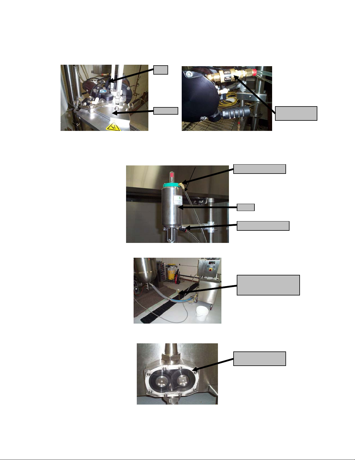
Clips
Die Area
WARNING: If a clip jams in the die area of the Tipper Tie clipper, do NOT attempt to cycle
the machine again until the jam is cleared. Follow ALL safety procedures! Place the air
switch in the OFF position and disconnect the air supply BEFORE attempting to REMOVE
the clip or other obstruction from the die area.
WARNING: Disconnect both air hoses on the air operated ball valve BEFORE disassembly.
Air Hose Connection
Valve
Air Hose Connection
Clipper Air Turn
Off Valve
Electrical Cord
DO NOT LAY ON
FLOOR IN WATE
WARNING: The CKPF/3 Mobile Pump/Fill Station electrical power cord should NOT be on
the floor in a water or moisture environment.
WARNING: Do NOT operate the CKPF/3 Mobile Pump/Fill Station with the pump rotor
housing cover removed, or without ALL bolts installed.
Operator’s Manual page 5 OM-CKPF/3
Rev. 1 2-6-03
Pump Rotor Housing
Cover
Page 6
CKPF/3 MOBILE PUMP/FILL STATION
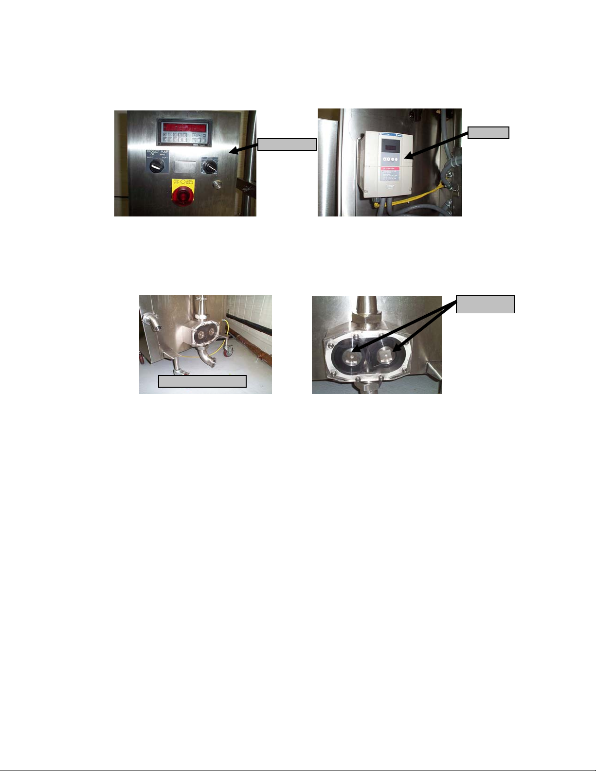
r
p
Operator Warnings Continued
Control Panel
Inverte
WARNING: Do NOT spray the CKPF/3 Mobile Pump/Fill Station control panel or inverter
with water.
CAUTION: When Working with the parts of the product supply system, be careful the metal
surfaces and housing may be HOT.
Back View of Pum
CAUTION: When removing the rotor housing from the CKPF/3 Mobile Pump/Fill Station,
ensure that you have a good grip on both sides of the housing and slowly pull the housing
toward you. Rotors may be HOT. REMOVE rotors with tool. Keep your feet and other
objects clear of the rotor housing during rotor removal and installation.
CAUTION: REMOVE product tubes and rotors BEFORE removing rotor housing.
CAUTION: Unit MUST have a separate ground wire for safe operation.
Pump Rotors
Operator’s Manual page 6 OM-CKPF/3
Rev. 1 2-6-03
Page 7
CKPF/3 MOBILE PUMP/FILL STATION
Equipment Description
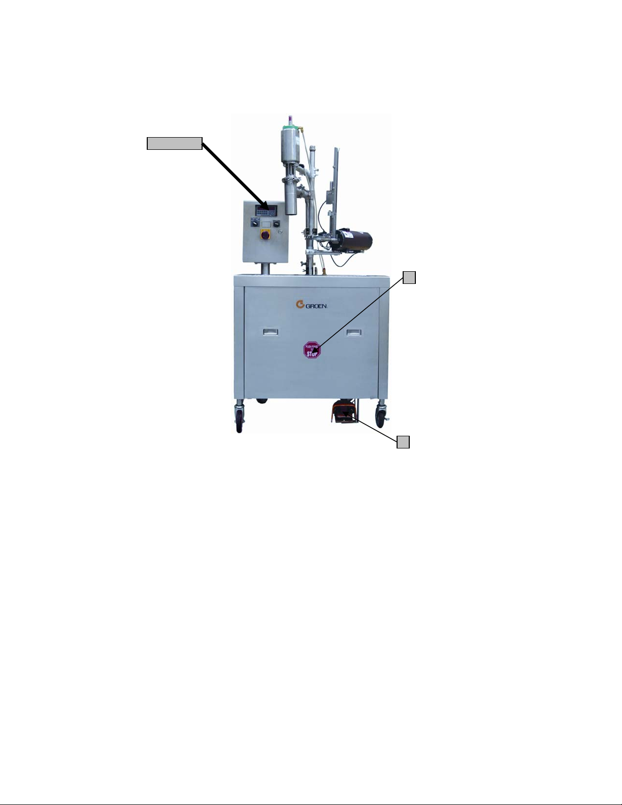
General Description/Mini-Spec:
The CapKold CKPF/3 Mobile Pump/Fill Station is designed to rapidly and gently transfer HOT or
cold food from one or more adjacent jacketed steam kettles into flexible plastic casings or other
containers. The pedestal-mounted control package allows fast and simple adjustment of pumping
speed to accommodate a broad range of products and accurate control of pre-measured volume.
The rotary pump will transfer product with food solids up to I¼" (32mm) diameter, without
damage.
Standard features
1. Integrated positive displacement pump, exterior rear-mounted for easy cleaning
2. Air-operated casing clipper, complete with regulator and filter
3. 15-foot air hose supplied for easy field connection
4. All stainless steel construction
5. Unit designed to accommodate of right-to-left operator fill sequence
6. Quick action air-activated product flow control valve
7. USDA food transfer hose—two (2) hose sections, 3-inch diameter by 3 feet long, with
fittings to interconnect Kettle and CKPF/3 Mobile Pump/Fill Station
8. Full surface spill tray with drain and removable stainless steel grate
9. Manufactured to latest sanitary standards and HACCP-compliant
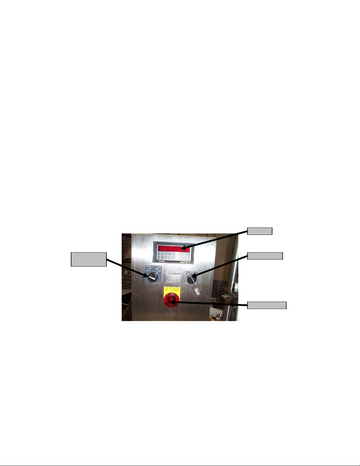
Standard integral control package
Controller
Product Pump
Control
The control panel is pedestal-mounted to the fill station and provided with a water- resistant case
to simplify cleanup and protect solid-state control systems. The raised control panel reduces
operator fatigue and simplifies pump speed and volume setting changes for different products.
Speed Control
On/Off Button
Operator’s Manual page 7 OM-CKPF/3
Rev. 1 2-6-03
Page 8
CKPF/3 MOBILE PUMP/FILL STATION
Equipment Description Continued
1, 2, & 5
4
The operating controls include:
Selection OFF for manual, metered or continuous pumping modes
1. Operator input of pump speed from 0 to 20 gallons per minute (GPM)
2. Operator input of metered volume from .0 to 10 gallons in 0.01 gallon increments
3. Foot-activated fill switch
4. Knee-and hand-operated STOP switches
5. LED digital display of volume pumped per casing, total casings pumped and total fill
volume per batch
3
Optional features and accessories
• Temperature monitor with casing clipper lockout, to prevent packaging at less than
180°F
• Product temperature recorder
• High volume air ejector-type vacuum pump (for reducing product packaging size in
cook tank production)
• Empty casing holding bin (hangs on the side of the CKPF/3 Mobile Pump/Fill Station)
• Pan fill adapter
• Manual KIWI label maker with one set of letters and initial ink supply (for contents
and production date labeling on Tyvek tape labels)
• Data Max Labeler
• Additional 3-foot food transfer hose section with fittings
• Prison package
Operator’s Manual page 8 OM-CKPF/3
Rev. 1 2-6-03
Page 9

CKPF/3 MOBILE PUMP/FILL STATION
Installation and Start-up
The CapKold CKPF/3 Mobile Pump/Fill Station is a mobile unit. Carefully REMOVE the unit from
its crate. If you note any damage to the equipment or the crate, notify the delivery agent
immediately. Ensure that no associated loose parts are thrown away with the packing materials.
Move the station to its intended location. Check the casters to see that they are inserted fully into
the leg sockets.
The CapKold CKPF/3 Mobile Pump/Fill Station is equipped with a Casing Tipper Tie Clipper.
Compressed air MUST be supplied at sufficient pressure to maintain an air regulator setting
between 80 PSI and 90 PSI minimum on the clipper. Operation of the clipper at 10 cycles per
minute will require approximately 60 CFM bursts of clean dry air. Inadequate air supply will
cause the clipper to malfunction. A 15-foot flexible hose terminated with a quick disconnect fitting
is supplied for connecting the CKPF/3 Mobile Pump/Fill Station to your facility’s compressed air
supply.
Electric power MUST be supplied to the power cord, which can run in any direction from beneath
the cabinet. The cord is equipped with a twist-lock plug that requires a NEMA L6-30R receptacle
(Hubbell 2621 or equivalent). Power supplied MUST be 1PH, 50 or 60 HZ and in the voltage
range of 208-240 AMP. The unit will pull approximately 20 Amps maximum. THE CIRCUIT
MUST BE PROPERLY GROUNDED.
Pump
Before using the pump fill station it is recommended that the unit be cleaned and sanitized for
use.
Step One. Remove the pump cover and rotors. Inspect the pump cavity. Then wash the cavity
and rotors with HOT water and detergent. Rinse the equipment well. Slide the rotors back on to
the shafts, taking care to match the mating corners of the shaft (a new paper gasket is required
each time you clean the pump.) Install the pump cover with the edge stamped TOP uppermost.
Tighten the eight nuts with the furnished cross-wrench.
Operator’s Manual page 9 OM-CKPF/3
Rev. 1 2-6-03
Page 10

CKPF/3 MOBILE PUMP/FILL STATION
r
Installation and Start-up Continued
3” Nut
Cover Nuts
Rotors
Pump Shafts
Sanitary
Thread Elbow
Install the 3-inch sanitary thread elbow on the sanitary inlet at the bottom of the pump. Connect
the 3-inch sanitary hose to the elbow and to the outlet fitting on the kettle. When everything is
located as desired, tighten the 3-inch nuts with the furnished aluminum wrench.
Air Regulator
Adjust the air pressure regulators between 80 PSI and 90 PSI.
Sanitary Hoses
Oile
Check the oil level in the lubricator bowl. Use the squeeze bottle to add oil, if necessary. A light
application of oil to the clipping parts of the Casing Clipper will give smoother operation.
Operator’s Manual page 10 OM-CKPF/3
Rev. 1 2-6-03
Page 11

CKPF/3 MOBILE PUMP/FILL STATION
Operation
1. Connect air and electrical connectors
2. Connect food transfer hose to the desired kettle
3. Load magazine with clips, then check printer and label paper, if applicable.
Air Connection
Selector Switch Knob
Air On, Indicator
Turned Counter
Clock Wise, Left
Position
4. Turn air valve to UP position. Make sure the 4-position selector switch is in the OFF
position.
Air Off, Indicator
Turned Clock
Wise, Up Position
Power Cord Plug
Operator’s Manual page 11 OM-CKPF/3
Rev. 1 2-6-03
Page 12

CKPF/3 MOBILE PUMP/FILL STATION
Product Pump Control
STOP Knob
Control Panel
Speed Control
5. Turn control power on by pulling
6. Sanitize the pump and adjacent piping (refer to chemical manufactures recommended
procedures and recommendations) by pumping HOT water through (not to exceed 140ºF):
a. Connect the product suction line to the kettle
b. Divert the spout to a drain
c. Allow HOT water to enter the pump, then turn control panel selector switch to
CONTINOUS and step ON the foot switch
d. Adjust the pump speed to desired flow rate
e. Let the HOT water run out of the kettle, then turn the control panel selector switch
to OFF
7. Use an approved commercial sanitization agent and follow directions
STOP knob
Operator’s Manual page 12 OM-CKPF/3
Rev. 1 2-6-03
Page 13

CKPF/3 MOBILE PUMP/FILL STATION
Operation Continued
8. Set the batch size:
a. Press ∆ to scroll UP or ∇ to scroll DOWN to P1
b. Press key until PGM flashes in the left corner of the read-out panel
c. Press CLR to clear
d. Set each batch volume (example: “1”, “5”, “0”, ENT —for approximately 1½ gallons
of food per bag)
e. Test setting in AUTO Mode and make necessary adjustments to P1 mode until
desired results are obtained
f. Press key to set program and return to RUN mode
g. Turn selector switch to AUTO
h. Place high barrier flexible packaging bag over the pump spout
Pump Spout
Operator’s Manual page 13 OM-CKPF/3
Rev. 1 2-6-03
Page 14

CKPF/3 MOBILE PUMP/FILL STATION
Operation Continued
Foot Switch
i. Depress foot switch one
Clipper Slot
Position the area of the bag between both hands into the clipper slot, gently pulling the
bag toward you (clipper will clip and cut top of bag OFF)
j. REMOVE clipped bag by backing down out of clipper slot
time per bag
9. Pump Warm-up (this procedure allows the pump body to warm up and the rotors to expand
in order to pump product at uniform quantities):
Product Pump
Control
Selector
Switch
Turn selector switch to MANUAL
a. Set a clean empty container under the outlet spout
Operator’s Manual page 14 OM-CKPF/3
Rev. 1 2-6-03
Page 15

CKPF/3 MOBILE PUMP/FILL STATION
Operation Continued
b. Depress and hold the foot switch pedal until the container is filled with product (to
STOP the pump, simply take your foot OFF the foot switch pedal)
c. Pour the contents of the container back into the kettle (repeat these steps as
necessary)
10. Pump product into bags:
a. Turn the selector switch to AUTO
b. Place high barrier flexible packaging bag over the pump spout
c. Depress foot switch one time
d. Empty each bag of most of its air by keeping the right hand just above the product
level, while squeezing air out toward the bag opening with the other hand
e. Place entire top of bag into the clipper slot and gently pull toward
you (clipper will clip and cut top of bag OFF)
11. Place each bag into the product chilling device
Between Batches
REMOVE any food product trapped inside the kettle that may affect the next batch Rinse
out kettle at the end of each batch.
a. Pump at HIGHEST speed until water
runs clear
b. Turn rinse water OFF and when kettle is
empty, turn pump OFF and CLOSE
kettle flush valve
c. Start next batch
Thermal Assurance Option
Thermal Assurance is provided in the system for operations that require clipping of bags
with product at or above a minimum set temperature. The default value is <180°F>. This
means that the product packaged is at or above 180°F (at this temperature, product is
pasteurized).
During tests, the set point temperature could be lowered to below ambient temperature
for clipper to operate. However, the set point should be set to a minimum of 180°F for
normal operation.
See Temperature Controller Manual for detailed information.
per bag
Operator’s Manual page 15 OM-CKPF/3
Rev. 1 2-6-03
Page 16

p
CKPF/3 MOBILE PUMP/FILL STATION
Equipment Cleaning/Sanitization Procedures
Fill Valve
Tipper Tie Clipper
Pump Discharge Tubing
Pum
Product In feed
All parts of the equipment should be cleaned with ambient water plus chlorine sanitization
agent. Equipment sanitization should be done, with 200 ppm chlorine water.
BEFORE kettle use, the agitator kettle should be filled with water and an approved
commercial sanitization agent, following directions. Agitate for several minutes. Pump out
the water via the Pump/Fill Station. This will sanitize the Pump/Fill hose and pump
assembly. Other kettles need only to empty the sanitizing solution to the drain and rinse.
Between product batches, rinse the kettle. Adding water and pump at the HIGHEST
CONTINUOUS speed until water runs clear.
System Cleaning and Disassembly
At the END of each day disassemble and clean system. REMOVE and clean scrapper blades,
blade holders, drop-down valve and outlet fitting. Clean kettle using high-pressure hose spray
and brushes. Do NOT use stainless steel scrub pads or other materials which may scratch kettle
surface. Reassemble kettle.
Food Transfer Hose
Disassemble and clean, using high-pressure food transfer hose and brush, and then reassemble.
REMOVE the sanitary hose, then wash the fittings and hose with a hose brush long enough to
reach all parts of the hose. NOTE: May clean all components except gaskets and pump rotors in
pot washing machine.
Pump/Fill Station
Disassemble entire pumping path assembly. Disassemble pump, including removal of pump
rotors, pump body and seals. Clean pump components and sanitize with an approved
commercial sanitization agent. Clean top shelf and sides of the Pump/Fill Station. REMOVE the
Equipment Cleaning/Sanitization Procedures Continued
pump cover and rotors and clean them in the wash sink. Loosen the 2-inch piping and
Operator’s Manual page 16 OM-CKPF/3
Rev. 1 2-6-03
Page 17

CKPF/3 MOBILE PUMP/FILL STATION
disassemble the pipe fittings and valve. REMOVE the pump shaft seals.
Pump Reassembly
Place lip seals firmly in pump body with attachment bolts and push on drive shafts, ensuring that
notch on rotor align with notch (dot) on drive shaft. Put new paper gasket in place. Attach cover
plate and tighten with tool—do NOT over-tighten. Water line should be wiped clean with an
approved commercial sanitization agent.
Cleaning Instructions:
When you are finished with a kettle load and are ready to clean up, CLOSE the kettle outlet valve,
rinse the kettle down with high-velocity water spray, and brush to clean the kettle to your
satisfaction. Then OPEN the kettle outlet valve. Turn the switch to CONTINUOUS. The pump
will run CONTINUOUSLY and the kettle will empty completely through the pump. The
wastewater will flow into filler sink, down the drain hose and on to the floor drain. If you wish to
minimize the BOD rating due to debris in the wastewater, an option is to use a strainer or pores
bag to remove the solids. This arrangement effectively strains solids out of your pumped cleanup water. This procedure will usually suffice for a between batch cleaning.
At the END of a day’s run, pump HOT water with a small amount of detergent through the
system. Pump the system empty. THEN SHUT OFF ELECTRIC POWER
unplugging the unit.
REMOVE the sanitary hose, then wash the fittings and hose with a hose brush long enough to
reach all parts of the hose. REMOVE the pump cover and rotors and clean them in the wash
sink. Loosen the 2-inch piping and disassemble the pipe fittings and valve. REMOVE the pump
shaft seals.
Wash and scrub down the exterior of the cabinet. Use a damp wet cloth with mild soap to clean
the control panel. DO NOT SPRAY ELECTRIC CONTROLS
We recommend that you consult with your local supplier of commercial cleaning supplies on the
proper chemicals for cleaning and sanitizing your Pump/Fill Station and other equipment. The
supplier is in direct contact with technical advisors who know the best methods for cleaning with
the water in your specific area.
with a high-pressure hose.
TO THE SYSTEM by
Operator’s Manual page 17 OM-CKPF/3
Rev. 1 2-6-03
Page 18

CKPF/3 MOBILE PUMP/FILL STATION
Maintenance Schedule
The CKPF/3 Mobile Pump/Fill Station requires regular maintenance. Please refer to the
maintenance schedule for the Pump and Tipper Tie Clipper below.
Pump
Schedule
Inspect rotors for nicks, cuts or separation from Daily
the metal base.
Inspect lip seals for integrity-NOT split, cut or Daily
frayed.
Maintenance Schedule Continued
Check oil levels in the pump and drive gearboxes. Weekly
Change oil in the drive and pump gearboxes. Semi-annually
Use Shell Turbo Oil 100 or equivalent.
Tipper Tie Clipper
Inspect oiler and add oil if required. Add a light Daily
weight mineral oil.
Inspect air lines. Should NOT be taut, pinched or Daily
bound.
Inspect cut-off knife for severe nicks or dullness. Monthly
Inspect oiler drip rate: adjust if necessary, to 1 Monthly
drop per 6 strokes.
Inspect clipper for tightness of clip by filling a Monthly
casing with water, clipping closely (i.e. very little
or no slack), then apply pressure to the casing (i.e.
stand on the casing). Look for signs of leakage.
Schedule
Operator’s Manual page 18 OM-CKPF/3
Rev. 1 2-6-03
Page 19

CKPF/3 MOBILE PUMP/FILL STATION
Troubleshooting
The CapKold CKPF/3 Mobile Pump/Fill Station is designed to operate smoothly and efficiently if
properly maintained. However, the following is a list of checks to make in the event of a problem.
Wiring diagrams are furnished inside the service panel and in its manual. If an item on the
check list is marked with (X), it means that the work should be done by an authorized
Groen service agent.
SYMPTOM WHO WHAT TO CHECK
Unit will not pump User a. Pull the emergency STOP switch out.
b. Turn the air switch ON.
c. Is the lower front cabinet panel installed correctly?
d. Connect the electric and air lines.
e. Prime food transfer hoses with water.
f. Valve on kettle is NOT open.
g. Turn selector switch to proper position.
h. Pump motor damaged (X)
i. Ball valve assembly damaged. (X)
Tipper Tie will not operate User a. REMOVE jammed clips.
b. Turn the air switch ON.
c. Is there a minimum of 90 PSI air pressure?
d. Are there clips in the loader?
e. Product temperature is below 82°C.
f. Tipper Tie is damaged. (X)
g. Is there oil in lubricator?
h. Is there water in system?
i. Is FRL plugged in?
Bags fill too fast/slow User a. Adjust pump speed.
b. Replace worn or damaged pump rotors.
Bags fill at improper level User a. Adjust fill volume.
b. Are the food transfer hoses blocked?
Hoses leaking User a. Replace worn or missing gaskets.
b. Tighten nuts.
Reference material for the options on your CKPF/3 Mobile Pump/Fill Station is included. Refer to
the reference material if problems arise.
Operator’s Manual page 19 OM-CKPF/3
Rev. 1 2-6-03
Page 20

CKPF/3 MOBILE PUMP/FILL STATION
Suggested Spare Parts List
To order CapKold parts, contact your local authorized Groen Service Agency or contact the
CapKold Business Office at 601/371-6039 to see if you are eligible for the CapKold Parts Direct
direct parts program. Please supply model designation, serial number, part number, part
description and quantity. When applicable, please also supply voltage and phase.
CapKold Recommended
Part Description
Replacement Switch for Foot Switch 056696 1
Switch Micro Plunger Type (Knee Switch) 005329 1
Valve Solenoid Air 3-Way (Shut Off) 115532 1
2” Sanitary Clamp N53786 2
Gasket Tri-Clamp 2" 016602 4
Gasket Bevel Seat 3" 005829 2
Gasket Tri-Clamp 3" 053362 2
Wrench Hex 3" 005322 1
Valve Solenoid Air 5-Way N110490 1
Air Pressure Regulator 115533 1
Air Filter/Lubricator 115571 1
Air Muffler 115555 1
Caster 5" Wheel Swivel Type with Brake 115509 1
Hose Assembly 3" Sanitary 2 Piece 078842 1
3-Way Valve 115532 1
Inline Fill Valve Assembly 2" Complete 143072 1
Kit "O" Ring & Seals 1143075 1
Stem Protector 142878 1
Pneumatic Air Cylinder 142881 1
Valve Piston Body 142883 1
Valve Piston Seal 142884 1
End Cap, Air Cylinder 142895 1
Valve Lower Body 142908 1
Drain Hose 2" ID X 2.375" OD 115551 Per Ft.
Motor Drive 1½HP 208/346VAC/3PH/60HZ 120437 1
Inverter 2HP 230VAC 120436 1
Controller Programmable Dynapar 115587 1
Pump Positive Displacement #6 Crepaco Complete 005324 1
Studs Long Round for Crepaco #6 Pump (need 3) N103533 3
Paper Gasket #6 Crepaco Pump 110898 1 Box
O-Ring #6 Crepaco Pump 005887 4
Seal Shaft #6 Crepaco Pump 005886 4
Seal Bearing #6 Crepaco Pump 060108 2
Rotor Single Lobe #6 Crepaco Pump 027179 2
Oil Food Grade #6 Crepaco Pump Gearbox 099733 1-5 Gallons
Cross Wrench #6 Crepaco Pump 005339 1
Wrench Spanner #6 Crepaco Pump N91459 1
3" Incline Ball Valve 112235 1
Part Number Quantity
Operator’s Manual page 20 OM-CKPF/3
Rev. 1 2-6-03
Page 21

CKPF/3 MOBILE PUMP/FILL STATION
Suggested Spare Parts List Continued
CapKold Recommended
Part Description
Clipper Tipper Tie Complete Assembly 097113 1
Cut-Off Knife for #Z4135 Tipper Clipper N47732 1
Punch for #Z4135 Tipper Clipper N65097 1
Die #Z4135 Tipper Clipper N65098 1
Spring Gate Holding Tipper Tie N61302 1
Channel Guard Assembly Clipper TT008397 1
Channel Guard Clipper TT098399 1
Spring Torsion Channel Guard N83759 1
Sensor End-of-Stroke Clipper N116455 1
Oil-Light Weight Clipper N83503 1 Bottle
Marking Wheel Label Maker 059509 1
Sleeve Rubber Marking Wheel 087864 1
Inking Wheel Label Maker 070431 2
Ink Label Maker 076266 1 Bottle
Conditioner (Ink Cleaner) Label Maker N93570 1 Bottle
Tape Labeling 2" x 300 Ft. Roll Label Maker 059495 5 Rolls
Letter Kit #518 083580 1
Letter Kit #516 N111849 1
Pump/Fill Relocation Kit 131218 1
4-Position Selector Switch N114275 1
Temp Sensor 115512 1
2-Way Poppet Valve 097190 1
Hose for #78842 Only 102174 Per Ft.
Ink Bottle 076366 1
Clips N80084 1 Case
Part Number Quantity
Operator’s Manual page 21 OM-CKPF/3
Rev. 1 2-6-03
Page 22

Schematic
CKPF/3 MOBILE PUMP/FILL STATION
Operator’s Manual page 22 OM-CKPF/3
Rev. 1 2-6-03
Page 23

CKPF/3 MOBILE PUMP/FILL STATION
Service Log
Model No._______________________ Purchased From____________________
Serial No._______________________ Location___________________________
Date Purchased__________________ Date Installed_______________________
Purchase Order No._______________ For Service Call_____________________
Date
Maintenance Performed Performed by
Operator’s Manual page 23 OM-CKPF/3
Rev. 1 2-6-03
Page 24

CKPF/3 MOBILE PUMP/FILL STATION
Limited Warranty to Commercial Purchasers*
(Domestic U.S., Hawaii & Canadian Sales Only)
CapKold Equipment ("CapKold Equipment") has been skillfully manufactured, carefully
inspected and packaged to meet rigid standards of excellence. CapKold warrants its Equipment
to be free from defects in material and workmanship for twelve (12) months with the following
conditions and subject to the following limitations.
I. This parts and labor warranty is limited to CapKold Equipment sold to the original
commercial purchaser/users (but not original equipment manufacturers), at its original
place of installation in the continental United States, Hawaii and Canada.
II. Damage during shipment is to be reported to the carrier, is not covered under this warranty,
and is the sole responsibility of purchaser/user.
III. CapKold, or an authorized service representative, will repair or replace, at CapKold's sole
election, any CapKold Equipment, including but not limited to, safety valves, tipper tie,
pump, motor, air components, ball valve, and electric components, found to be defective
during the warranty period. As to warranty service in the territory described above, CapKold
will absorb labor and portal to portal transportation costs (time & mileage) for the first
twelve (12) months from date of installation or fifteen (15) months from date of shipment
from Groen.
IV. This warranty does not cover calibration, periodic adjustments as specified in operating
instructions or manuals, and consumable parts such as pump motors, gaskets, packing,
etc., or labor costs incurred for removal of adjacent equipment or objects to gain access to
CapKold Equipment. This warranty does not cover defects caused by improper installation,
abuse, careless operation, or improper maintenance of equipment. This warranty does not
cover damage caused by poor water quality or improper boiler maintenance.
V. THIS WARRANTY IS EXCLUSIVE AND IS IN LIEU OF ALL OTHER WARRANTIES,
EXPRESSED OR IMPLIED, INCLUDING ANY IMPLIED WARRANTY OF
MERCHANTABILITY OR FITNESS FOR A PARTICULAR PURPOSE, EACH OF WHICH
IS HEREBY EXPRESSLY DISCLAIMED. THE REMEDIES DESCRIBED ABOVE ARE
EXCLUSIVE AND IN NO EVENT SHALL CAPKOLD BE LIABLE FOR SPECIAL,
CONSEQUENTIAL OR INCIDENTAL DAMAGES FOR THE BREACH OR DELAY IN
PERFORMANCE OF THIS WARRANTY.
VI. CapKold Equipment is for commercial use only. If sold as a component of another (O.E.M.)
manufacturer's equipment, or if used as a consumer product, such Equipment is sold AS IS
and without any warranty.
*(Covers All Equipment Ordered After October 1, 1995)
Operator’s Manual page 24 OM-CKPF/3
Rev. 1 2-6-03
 Loading...