

Page 1
OPERATOR MANUAL
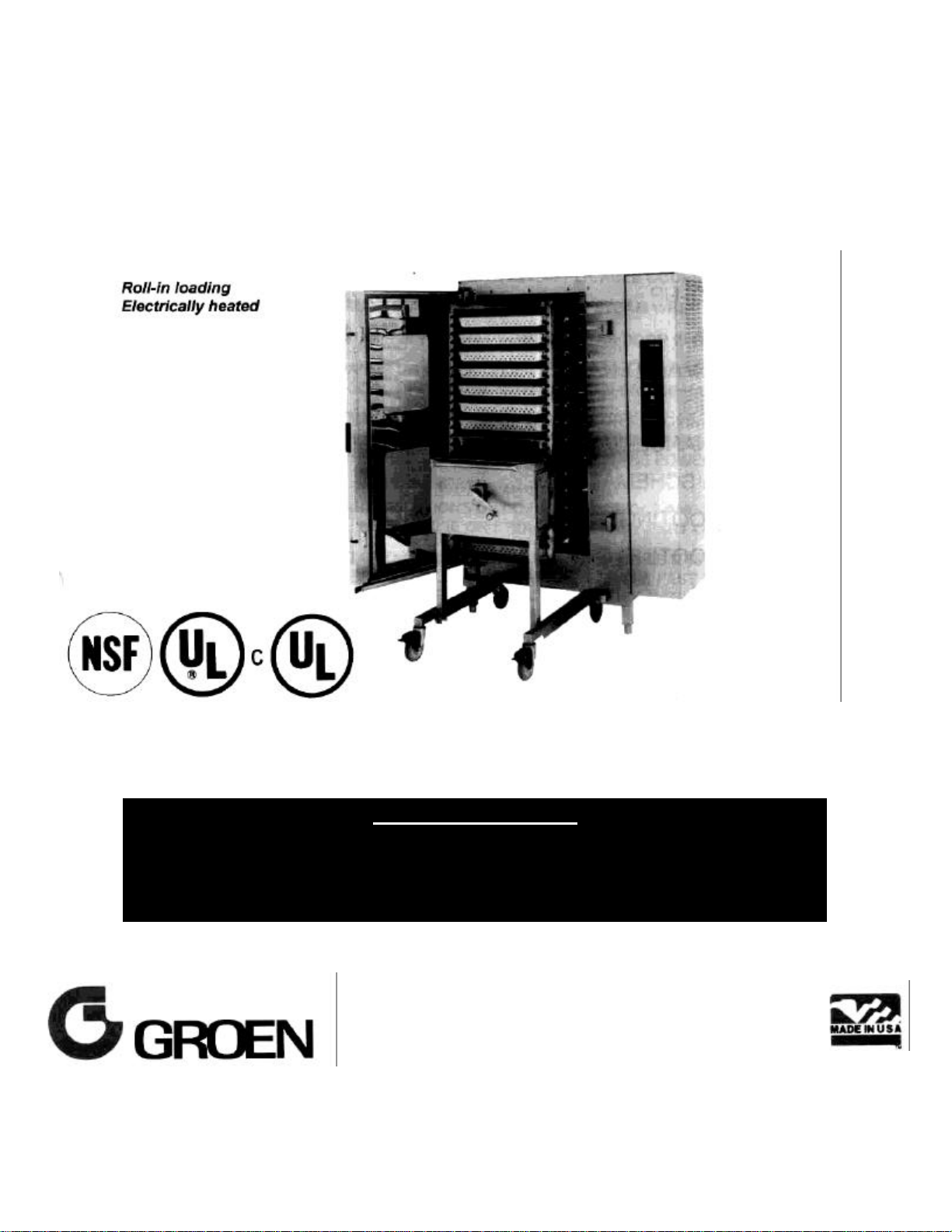
MODEL: CC40-E
Combo SuperSystem 40™
Combination Steamer-Oven
OM-CC40-E
THIS MANUAL MUST BE RETAINED FOR FUTURE REFERENCE. READ,
UNDERSTAND AND FOLLOW THE INSTRUCTIONS AND WARNINGS
CONTAINED IN THIS MANUAL.
FOR YOUR SAFETY
DO NOT STORE OR USE GASOLINE OR OTHER FLAMMABLE
VAPORS AND LIQUIDS IN THE VICINITY THIS OF ANY OTHER
APPLIANCE.
Page 2

Table of Contents
OPERATOR WARNINGS..........................................................................1
EQUIPMENT DESCRIPTION................................................................. 2, 3
WATER CONDITIONING...........................................................................4
INSTALLATION.............................................................................5, 6, 7, 8
INITIAL START-UP ...................................................................................9
OPERATION....................................... 10, 11, 12, 13, 14, 15, 16, 17, 18, 19
CLEANING & MAINTENANCE
CLEANING................................................................20, 21, 22, 23, 24
MAINTENANCE.............................................................................. 25
DIAGRAMS & SCHEMATICS ............................................................26, 27
TROUBLESHOOTING............................................................................. 28
TROUBLESHOOTING GUIDE................................................................. 29
REFERENCES....................................................................................... 30
SERVICE LOG ....................................................................................... 31
NOTES................................................................................................... 32
WARRANTY........................................................................................... 33
Page 3

IMPORTANT READ FIRST IMPORTANT
WARNING: BE SURE ALL OPERATORS READ, UNDERSTAND, AND FOLLOW THE
DANGER: ELECTRICALLY GROUND THE UNIT AT THE TERMINAL PROVIDED. FAILURE TO
WARNING: THE UNIT MUST BE INSTALLED BY PERSONNEL QUALIFIED TO WORK WITH
TO PERSONNEL AND/OR DAMAGE TO THE EQUIPMENT. THE UNIT MUST BE
WARNING: STEAM CAN CAUSE BURNS. AVOID ESCAPING STEAM WHEN OPENING DOOR.
WARNING: STAY AWAY FROM HOT AIR THAT COMES OUT AS DOOR IS OPENED.
WARNING: DO NOT PUT HANDS OR OTHER OBJECTS INTO THE COOKING CHAMBER
WARNING: BEFORE CLEANING THE OUTSIDE OF THE UNIT OR REMOVING ANY PARTITION
OR PANEL, ALWAYS SWITCH OFF THE ELECTRIC POWER. BEFORE WORKING
WARNING: KEEP WATER AND SOLUTIONS OUT OF ALL CONTROLS AND ELECTRICAL
COMPONENTS. NEVER HOSE OR STEAM CLEAN ANY PART OF THE UNIT.
OPERATING INSTRUCTIONS, CAUTIONS, AND SAFETY INSTRUCTIONS
CONTAINED IN THIS MANUAL.
GROUND THE UNIT COULD RESULT IN ELECTROCUTION AND DEATH.
ELECTRICITY AND PLUMBING. IMPROPER INSTALLATION CAN CAUSE INJURY
INSTALLED IN ACCORDANCE WITH ALL APPLICABLE CODES.
DURING FAST COOL OPERATION. ROTATING FAN CAN BE HAZARDOUS.
ON ANY ELECTRICAL COMPONENT, DISCONNECT THE POWER SOURCE FROM
THE UNIT.
WARNING: DO NOT TRY TO CLEAN THE COOKING CHAMBER WHILE IT IS HOT FROM
OPERATION IN THE OVEN OR COMBO MODE. SEE THE FAST COOL
WARNING: DO NOT MIX DE-LIMING AGENT (ACID) AND DEGREASER (ALKALI) IN THE
STEAM GENERATOR OR ON THE COOKING CHAMBER WALLS. REFER TO
WARNING: BEFORE YOU REACH INTO THE OVEN TO REMOVE PARTITIONS, EXIT THE FAST
UNTIL THE FANS HAVE STOPPED MOVING.
WARNING: AVOID ALL DIRECT CONTACT WITH HOT EQUIPMENT SURFACES. DIRECT SKIN
CAUTION: TAKE PRECAUTIONS TO AVOID CONTACT WITH ANY CLEANER, DE-LIMING
CLOTHING. CAREFULLY READ THE WARNINGS AND FOLLOW THE DIRECTIONS
INSTRUCTIONS IN THE OPERATION SECTION OF THIS MANUAL.
MANUFACTURERS INSTRUCTIONS.
COOL MODE AND SWITCH OFF THE POWER. DO NOT REACH IN THE OVEN
CONTACT COULD RESULT IN SEVERE BURNS.
AGENT, OR DEGREASER, AS RECOMMENDED BY THE SUPPLIER. MANY
CLEANERS ARE HARMFUL TO THE SKIN, EYES, MUCOUS MEMBRANES, AND
ON THE LABEL OF THE CLEANING AGENT.
1
Page 4
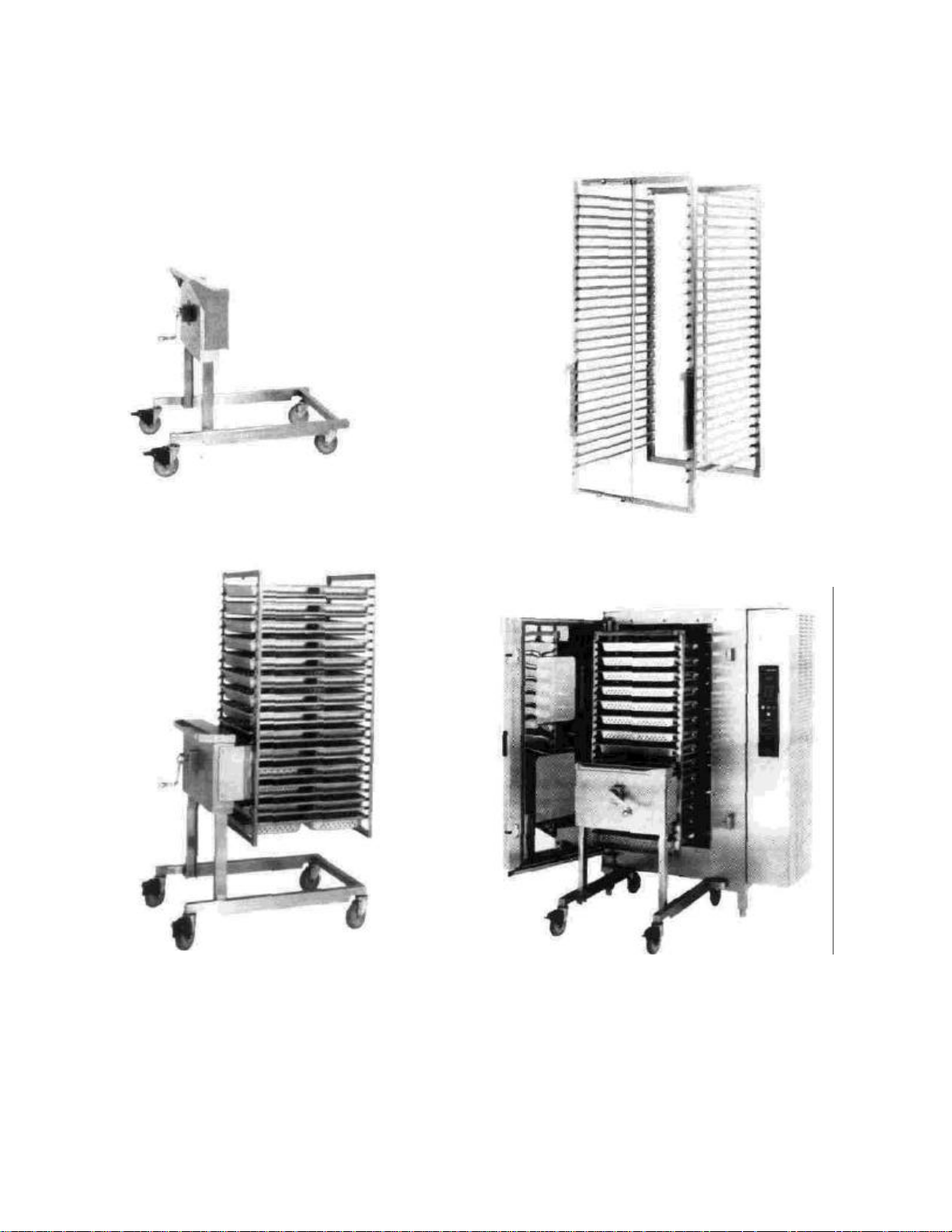
Transport Cart
Electric Combo SuperSystem 40
Pan Rack
Transport Cart With Pan Rack Locked
In Place For Loading Etc.
Combo SuperSystem 40 With Cart And
Rack In Loading Position
2
Page 5

Equipment Description
The Groen Convection Combo™ consists of a stainless steel cooking chamber, an air heating
compartment with electric heating elements and dual fans, a steam generator with electric heating
elements, and a control compartment housing electrical components.
All major components of the Convection Combo are encased in a 16 gauge stainless steel cabinet. Glass
fiber insulation, 1 to 2 inches thick, lines the cabinet.
The oven has a double door with two large, tempered glass windows in each door. Oven viewing lights are
mounted between the inner and outer doors. Separate hinges allow easy access to the space between the
doors for window cleaning and light fixture maintenance. A condensate collection tray at the bottom diverts
condensate to the oven drain. An optional solid door is available. The solid door does not provide viewing
lights.
All operator controls are on the front panel. Standard controls permit the Convection Combo to operate in
four modes:
1. As a convection oven
2. As a self-contained, pressureless steamer
3. As a combination oven-steamer
4. With the meat probe operating
Cooking chamber capacity:
28 Steam table pans (12 x 20 x 2-1/2"), or 20
Bake pans (18 x 26"), or 40 Gastronorm pans
(1/1)
All units are supplied on stainless steel legs.
Controls and monitoring displays for cooking time, operating mode, and temperature occupy the control
panel. The upper portion of the panel has a digital time readout and touch pads for setting the time. Below
the timer section are lights to indicate the status of the unit plus touch pads that select the mode of
operation and switch on the power. A digital readout shows the chosen temperature, which is selected with
a dial. Status of the pilot burners is indicated by the lights above the pilot ignition switch, located behind the
sliding door in the front of the unit.
An insulated steam generator is mounted next to the oven. Steam enters the cooking chamber through two
connecting tubes at the top and bottom on the right side of the cavity.
The air heating space, containing the heat exchanger tubes and fans, is separated from the cooking
chamber by removable right-hand and top partitions.
The compartment containing the automatic controls and other electrical components is on the right-hand
side of the unit and is entered by removing the right outside panel or by opening the hinged panel in the
front.
A drain is located in the floor of the cooking chamber. Fluids drain from the floor to the stainless steel drain
pipe outside the oven. This drain pipe includes a spray condenser, which suppresses any steam escaping
from the chamber. The drain assembly includes a built in vent with overflow protection.
The roll-in loading and unloading equipment for Combo SuperSystem 40 consists of the Model CCS "Smart
Cart" and the separate Model CRS rack. When the rack is engaged with the cart, a hand crank raises the
rack for transportation and lowers the rack to position it in the oven. The cart is disengaged from the rack and
removed before the oven door is closed. Design of the system allows the rack to be easily held in and
transferred between reach-in or walk-in refrigerators and freezers, blast chillers, and holding cabinets.
3
Page 6

Water Conditioning
It is desirable to supply the steamer with water that will not form scale. Scale formation depends on the hardness of
the water and the hours of operation. In a few areas of the United States, the water supply is sufficiently free of
minerals to avoid scale formation. However, most water supplies carry heavy loads of minerals, which will form scale
and possibly cause premature failure of components.
Your local water utility can provide a statement on the scale forming qualities of the water supply. Water
supplied to the boiler should contain not more than 30 parts per million total dissolved solids (TDS) and
should have a pH of 7.0 or higher.
Please follow these simple precautions:
1. Do not rely on "water treaters" commonly sold as scale preventers and scale removers. They do not
work. The only proven way to prevent scale build-up is to feed in water practically free of scale-forming
minerals.
2. If your water supply carries scale-forming minerals, as most water supplies do, run the water through a
properly maintained softener. Exchangeable softener cartridges or a regeneratable softener can be
used. In either case, establish a regular program of exchanging the cartridges or regenerating the
softener. Installing a water meter on the inlet line between the softener and the steamer will give an
accurate check of water consumption and a way of determining when to change the cartridge or
regenerate the softener. By using a softener and operating within the softener's capacity to exchange
minerals, the user will optimize performance and minimize maintenance of the steamer.
3. If you notice a slowing of steam production, have your authorized Groen service representative check
the unit for build-up of scale. Heavy scale will reduce the unit's ability to boil water and can cause a fire
tube in the steam generator to overheat and burn out.
TO MINIMIZE SCALE PROBLEMS, USE AND PROPERLY MAINTAIN A SOFTENER, AND CLEAN
THE STEAM GENERATOR PERIODICALLY OR AS NEEDED.
4
Page 7
A. Mounting
WARNING:
THE UNIT MUST BE INSTALLED
INSTALLATION CAN CAUSE
INJURY
TO PERSONNEL AND/OR
THE UNIT MUST BE INSTALLED IN
DANGER:
ELECTRICALLY GROUND THE UNIT AT THE TERMINAL PROVIDED.
Installation
NOTICE:
Do not install a unit in these locations:
• Where the right side vents are blocked or within 6 inches (15 cm) of any
combustible material or within 12 inches (31 cm) of a heat source, like a
braising pan, deep fryer, char broiler, or kettle.
• To the left of any open-flame equipment.
• With less than 7 inches (18 cm) of clearance at the rear.
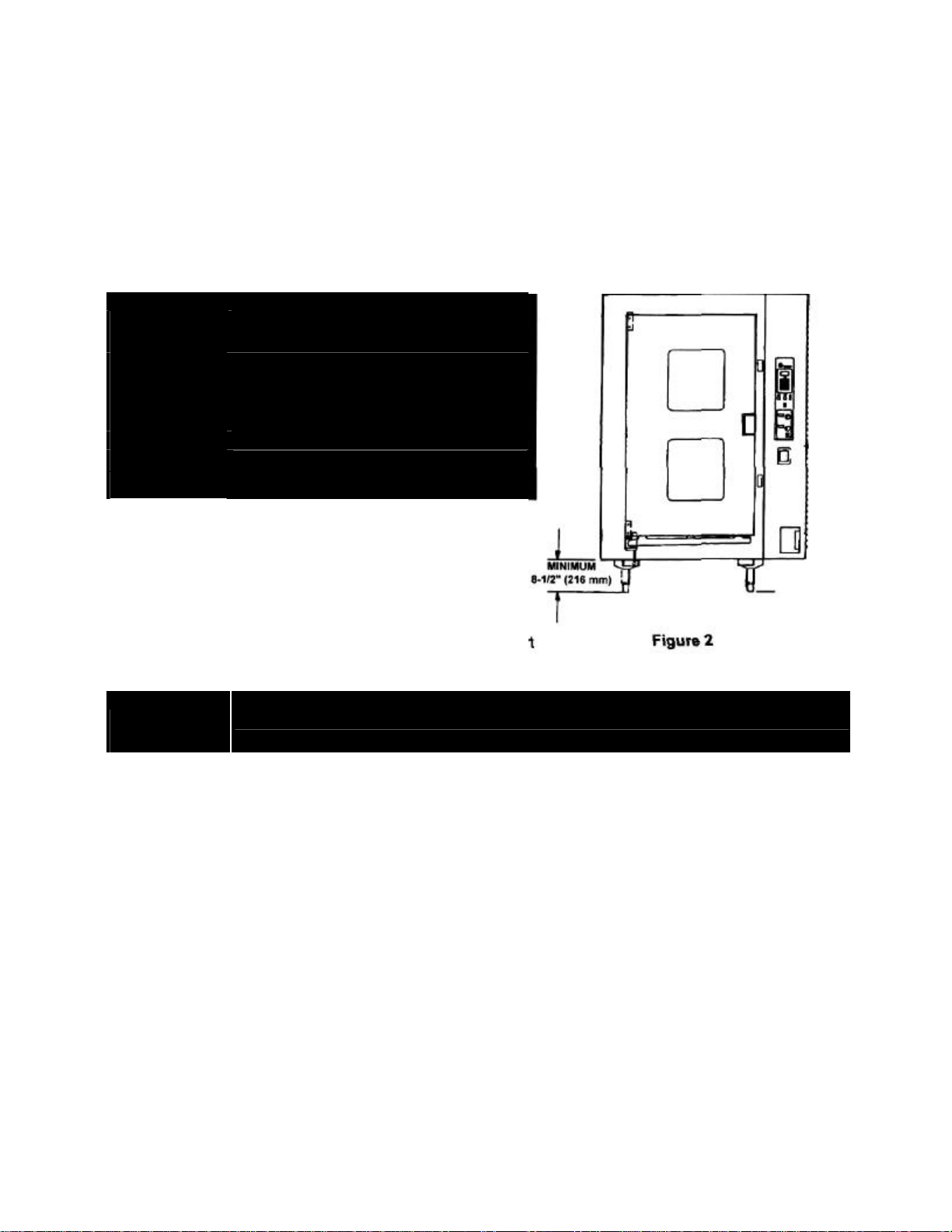
To avoid drainage problems, level the unit front-to-rear, or provide a slight pitch to the rear. Maintain a
minimum 8-1/2 inch (22 cm) clearance between the cabinet and the floor (Figure 2), to permit proper
operation of the cart.
BY PERSONNEL QUALIFIED TO
WORK WITH ELECTRICITY AND
PLUMBING. IMPROPER
DAMAGE TO THE EQUIPMENT.
ACCORDANCE WITH ALL
APPLICABLE CODES.
B. Electrical Supply Connection
Local codes and/or the National Electrical Code should be
observed in accordance with ANSI/ NFPA 70-1987 (or latest
edition). AN ELECTRICAL GROUND IS REQUIRED. The
electrical schematic is located in the service compartment
and in this manual. In Canada, provide electrical service in
accordance with the Canadian Electrical Code, CSA C22.1
Part 1, and/or local codes.
FAILURE TO GROUND THE UNIT COULD RESULT IN ELECTROCUTION
AND DEATH.
1. Panel Removal
The wiring and the control compartment are accessed by removing the right side panel. Remove
one screw at the back of the panel, then slide the panel toward the front of the unit. Set the panel
aside.
2. Supply Voltage
The CC40-E must operate at the rated nameplate voltage ±10%.
3. Terminal Block
The terminal block for incoming power is located at the back of the control compartment. The
ground terminal is located below the terminal block. The unit must have a separate ground wire
for safe operation. Minimum size of the ground wire is 6 AWG (4.5 mm) for a 200 Amp circuit or 8
AWG (3.5 mm) for a 100 Amp breaker.
5
Page 8
Installation (cont'd)
(3
Phase)
4. Supply Wire
To determine the type of wire needed for the power supply, find the operating voltage from the
back data plate. Refer to the "Electrical Supply Connection" label on the back of the unit for
correct wire size and insulation temperature rating.
The specified wire must be used to meet Underwriters Laboratories and National Electrical Code
requirements.
The knockout hole (Figure 3) is sized for a 2 inch (51 mm) conduit fitting.
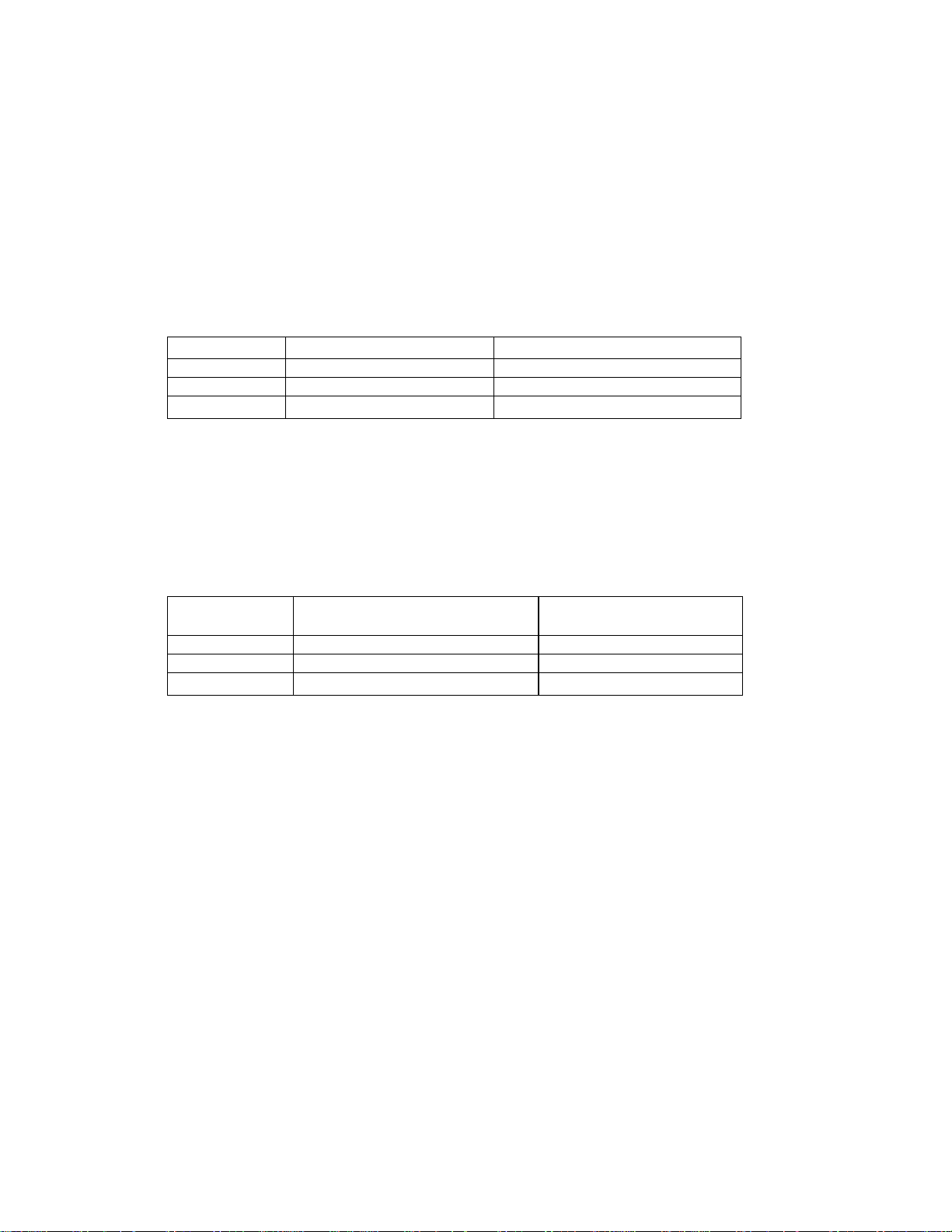
CC40-E ELECTRICAL SUPPLY CONNECTION
(All wires are copper only. Reference:
National Electrical Code.)
Voltage Size for 75°C (THWN) Size for 90°C (THHN)
208
240
480 #3 AWG (6 mm) #4 AWG (6 mm)
5. Branch Circuit Protection
It is strongly recommended that each Convection Combo have its own branch circuit protection.
N/A
N/A
2/0 AWG (10 mm)
1/0 AWG (9 mm)
CC40-E CURRENT DEMAND
Voltage Maximum Current per Line
208 155 A 56 KW
240 135 A 56 KW
480 67 A 56 KW
Maximum Power
Each current-carrying conductor must have overcurrent protection. Refer to the label on the rear
of the unit for proper wire size and type. Watertight connections to the unit are required.
6
Page 9
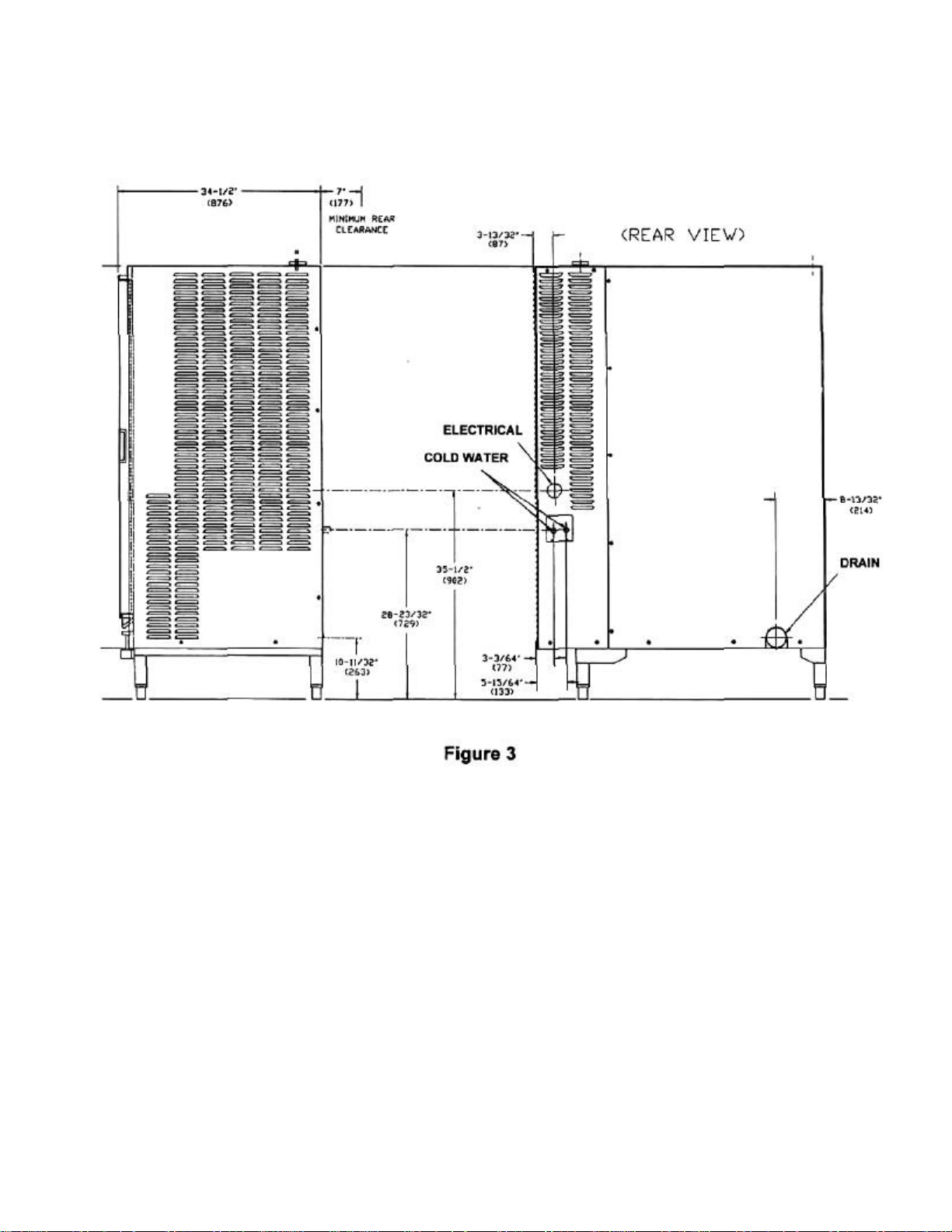
Convection Combo Utility Connections
7
Page 10
Installation (cont'd)
C. Water Supply Connection
Two water connections are required. One supplies water to the steam generator (treated water), and the
other is for the condensate spray (untreated water). A back siphonage device (check valve) must be
installed in each incoming cold water line according to local plumbing code. The water line pressure
should be between 30 and 60 PSIG (210 and 410 kPa). A pressure regulator is required above 60 PSIG
(410 kPa). Two 3/4 inch NH (garden hose type) connectors are required to connect the water supply to
the water inlet valves. The minimum diameter of each water feed line is 1/2 inch (13 mm). Use a washer
(or, if necessary, two washers) in the hose connection. Do not allow the connection to have any leak,
regardless of how small.
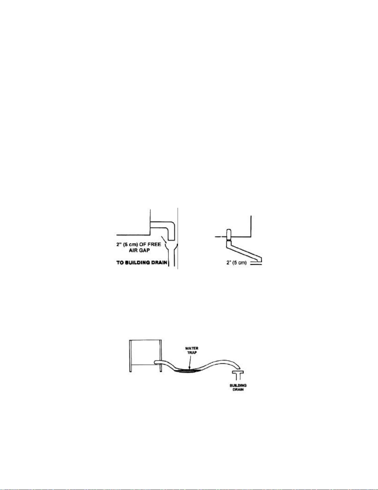
D. Drain Connection
A hose may be attached to the outlet of the drain by means of a clamp. Use 3" ID hose for CC40-E. The
hose may be connected directly to an atmospherically vented building drain.
The drain has a 2 inch (5 cm) air vent, which eliminates the need for a free air gap at the connection to the
building drain, unless such a gap (Figure 4) is required by local code. Do not block the air vent in any way.
Do not attach anything to the vent tube or reduce the size of the vent tube.
Do NOT use plastic pipe in the drain line, because the drain must withstand boiling water. Install the drain
line with a constant downward pitch. Do NOT create any water trap (Figure 5) in the line.
Proper Drain Line Connection
Figure 4
Improper Drain Line Connection
Figure 5
8
Page 11

Initial Start-Up
After the Combo SuperSystem has been installed, perform initial testing to ensure that the unit is operating
correctly.
1. Remove all literature and packing materials from the interior and exterior of the unit.
2. Make sure both cold water supply lines are open and none of the fittings is leaking.
3. Turn on electrical service to the unit.
4. High altitude operation. The altitude of operation can be programmed into the Convection Combo. At
altitudes above 2,000 feet, the unit will not operate in Steamer or Combo Mode unless the altitude is
set. To set the altitude:
a. If the unit is on, turn it off by pressing the ON touch pad.
b. Press and hold the STEAM touch pad while turning the unit on by pressing the ON touch pad. The
timer display will show the letters AL and a number that represents the altitude in thousands of feet. If
the altitude has never been set on your unit, the number displayed will be 1.
c. Enter the proper altitude value, between 1 and 15, using the numbered touch pads. For example, if
the unit will be used at an altitude of 7,000 feet, press the 7 touch pad.
d. Press the START touch pad.
5. To test Steamer Mode operation, turn on the unit. (For details of operating procedure, see the
Operation section of this manual.) Clear any time from the time display, close the door, and press the
STEAM touch pad. (If the HOT light is on, see the Fast Cool instructions in the Operation section.) The
WAIT light will stay on while the steam generator fills with water and heats the water. Within 15 minutes
the WAIT light should go off and the READY light should come on, indicating that the water has reached
the standby temperature. The timer controls operation (in Steamer Mode only), so enter a time, then
push START. The colon on the time display will blink, and the generator will begin to produce steam.
The timer will not count down, if the READY light is not lit.
WARNING: STEAM CAN CAUSE BURNS. AVOID ESCAPING STEAM WHEN OENING
DOOR.
IMPORTANT: You cannot change modes if the timer is running.
6. To test Combo Mode operation, turn the power on and clear any time from the timer display, Press
the COMBO touch pad. Set the COOK temperature to 300 F (150°C). The WAIT light will come on and
stay on, while (1) the steam generator fills with water and heats the water to standby temperature and
(2) the air heater raises air temperature to 300°F. Both actions should be completed in about 15
minutes, starting with a cold unit. Then the WAIT light will go off and the READY light will come on.
WARNING: STEAM CAN CAUSE BURNS. AVOID ESCAPING STEAM WHEN OENING
DOOR.
IMPORTANT: The timer does not control the oven in Combo Mode or Oven Mode.
7. To test Oven Mode operation, turn the power on and clear any time from the timer display. Press the
OVEN touch pad. Set the COOK temperature to 350°F (175°C). The WAIT light will come on. Within 10
minutes from a cold start, the WAIT light should go off and the READY light should come on. When that
happens, turn the COOK temperature setting down to 300°F (150°C). The HOT light will come on.
8. To test Meat Probe operation, turn the PROBE knob clockwise to activate the probe. Confirm that the
temperature shown in the TIME display is the actual temperature of the probe. Then turn the PROBE
knob counterclockwise to inactivate the probe.
9. To shut down the unit, first clear the timer. Then press the mode touch pad for the mode the unit is in.
Switch off the power.
10. If the Convection Combo behaves as described, the unit is functioning correctly and ready for use.
9
Page 12

Page 13

WARNING: BE SURE ALL OPERATORS READ,
AND SAFETY INSTRUCTIONS CONTAINED
UNDERSTAND, AND FOLLOW THE
OPERATING INSTRUCTIONS, CAUTIONS,
IN THIS MANUAL.
DO NOT OPERATE THE UNIT IN ANY
MODE, UNLESS ALL INTERIOR
PARTITIONS HAVE BEEN RETURNED TO
THEIR PROPER LOCATIONS.
NOTE: Before the control panel can be operated as
described in this Operation section, the pilot burner flame
must be established. See the Initial Start-Up section for
details.
A. Controls and Indicators
The control features routinely used by the operator are on
the right front side of the unit and are described as follows.
(Refer to Figure 7).
1. Time Section
In the Oven and Combo Modes of operation, the timer
functions only as a "cooking time minute minder" and
does not turn the unit on or off. In the Steamer Mode, the
timer controls the operation of the steaming function.
a. Display Window — Displays the operating time
remaining in the Steamer, Oven, or Combo Mode,
because the timer counts down. Format of the
display is "hours : minutes". Maximum minute
display accepted by the unit is 59. Any recipe
calling for more than 59 minutes should be
converted to hours and minutes format, e.g., 90
minutes is equal to 1 hour and 30 minutes. Display
will read 01:30.
b. Time touch pads — used to enter time values.
c. CLEAR — Pressing this touch pad once stops the
beeper and resets the timer to the timer that was
last set. Pressing twice clears the timer to 00:00.
(At the end of a cooking period, opening the door
has the same effect as pressing CLEAR once.)
d. START— Pressing this touch pad will start the timer
and, if the unit is in Steamer Mode, also cause
steaming to begin.
2. Status Lights
a. HOT— Indicates the chamber temperature is
more than 15°F (8°C) above the cook temperature
setting (see item 5 in this section).
11
Page 14

Operation (cont'd)
b. SERVICE — Indicates a problem that may require
a service call. If such a problem has occurred, the
beeper will sound and the SERVICE light will be
on, when power is switched on. The unit may
continue to operate, depending on the type of
problem. Refer to the Troubleshooting section to
determine the nature of the problem.
c. WAIT— Indicates the unit is either heating or
cooling toward the set temperature. The HOT and
WAIT lights will be on together, if the chamber is
more than 15°F (8°C) above the set point.
d. READY — Indicates the unit is ready for use.
3. Cooking Mode Selection
These touch pads are used to select the mode of
operation. If a mode is off, pressing the pad for that
mode will switch the mode on. If the mode is on,
pressing its pad will switch the mode off. A light just
above each pad shows which mode has been selected.
a. STEAM — Selects steamer operation.
b. COMBO—Selects combined steam and
convection oven operation.
c. OVEN — Selects operation of the convection
oven only.
4. Power
This touch pad is used to switch the unit on or off.
When power is on, the ON light just above the pad is lit
Use of this pad does not reset the controls, so the unit
will come on in the same mode it was in when it was
last switched off.
5. TEMP Section
a. The window displays the selected temperature in
either Oven or Combo Mode. It is blank in the
Steamer Mode.
b. Turning the knob selects the cooking temperature in
5°F increments. The control ranges are:
Oven Mode 200 to 500°P (95 to 260°C) Combo
Mode 220 to 500 F (105 to 2600C)
6. Meat Probe Selection
This rotating knob is used to turn on or off the hold function. By selecting a certain temperature
(ranging between 80°F and 200°F) the food can be maintained at a constant temperature for a fixed
amount of time.
7. Door Lights Selection
Door lights can be turned on/off to view the food inside by using this touch pad. These lights are not
available with the optional solid door.
12
Page 15

B. Operating Instructions
1. Steamer Mode
a. If the unit is off, switch on the electric power by
pushing the ON touch pad. (If the SERVICE
indicator lights when power is switched on, see
the Troubleshooting section.)
b. If power is already on and any number is showing
in the time display window, press the CLEAR
touch pad one or more times to reset the time
display to zero.
IMPORTANT: You cannot change mode while
the timer is running.
c. The unit will be in the mode of operation that was
used last, so the indicator for that mode will be lit.
If the unit is not already in Steamer Mode, press
the STEAM touch pad. The STEAM indicator will
light, and the TEMP window will go blank.
d. If the unit has just been used in Oven or Combo
Mode, lighting of the HOT indicator may show that
the cooking chamber is too hot for use as a
steamer. The unit can be cooled quickly to the
proper temperature range for steaming by leaving
the door open or by following the Fast Cool
procedure described near the end of this section.
While the door is open, the generator can fill and
heat water to 200°F, but it cannot produce steam.
e. The WAIT indicator will be lit until the water
reaches approximately 200°F (93°C). Then the
WAIT light will go off and the READY indicator will
light. You are now ready to steam foods in your
Convection Combo.
f. Load the food into the pan or pans so there is a
uniform layer.
g. Place the pans in the rack, which is on the cart. If
there are only a few pans, uniformly distribute them in
the center of the rack.
h. Press the numbered touch pads to set the cooking
time. The time set will appear in the time display
window. If you enter the wrong number, press the
CLEAR pad to erase the time from the display, then
set the time again.
i. Carefully open the door, then move the cart so the
rack goes into the oven cavity. Using the hand crank
lower the rack to the floor of the cavity. Remove the
cart and close the door.
13
Page 16

Operation (cont'd)
j. When the correct cooking time has been entered,
press the START pad. The colon will blink, and the
timer will count down the cooking time. (The unit
must be READY before the timer can count down.)
k. Opening the door during the cooking period stops
the production of steam and interrupts (but does
not reset) the timer. Closing the door allows
steaming and timing to continue.
WARNING: STEAM CAN CAUSE BURNS,
AVOID ESCAPING STEAM
I. When the timer has counted down to zero, it will
stop the generation of steam and sound a beeper
alarm. Water in the steam generator will be held at
the standby temperature (about 200°F or 93°C).
The beeper will continue until the door is opened or
the CLEAR pad is pressed.
m. Carefully open the door. If the food is cooked,
engage the cart with the rack, then crank the rack
up, and remove the rack from the oven.
n. After the timer display has counted down to zero,
opening the door or pressing CLEAR once will
reset the display to the time that was used last.
Pressing START will repeat the cook cycle. If the
same cooking time will be used repeatedly, you
need to press the number keys only when you first
use that time.
o. After the timer display has counted down to zero,
the timer can be reset to zero by either (1) opening
the door and pressing CLEAR or (2) pressing
CLEAR twice. A new cooking time must be set by
using the number keys.
2. Oven Mode
a. To use the Convection Combo as a convection
oven, first switch on the electric power by pushing
the ON touch pad. (If the SERVICE indicator lights
when the power is switched on, see the
Troubleshooting section.) The fan will begin to
operate, if the door is closed and the cooking
chamber temperature is above 200°F.
b. If power is already on and any number is showing in
the time display window, press the CLEAR touch
pad to erase the time display.
IMPORTANT: You cannot change mode while
c. The unit will be in the mode of operation that was
used last, so the indicator for that mode will light. If
the unit is not already in Oven Mode, press the
OVEN touch pad. The OVEN indicator will light,
and the oven fan will operate.
WHEN OPENING DOOR
the timer is running.
14
Page 17

D. Using the dial in the TEMP section of the control
panel, set the desired cooking temperature, which
will appear in the temperature display window
beside the dial. Unless the cooking chamber is
already at or above the set temperature, the unit
will begin heating the chamber, and the WAIT —indicator will light.
e. If the unit has just been used at a temperature
more than 15°F (8°C) higher than the desired
temperature, the HOT and WAIT indicators will
light. The unit can be cooled quickly to the correct
temperature by leaving the door open or by
following the Fast Cool procedure near the end of
this section.
f. The READY light will indicate when the oven is at
the desired temperature.
g. Load the food into the pan or pans so there is a
uniform layer.
h. Place the pans in the rack. which is on the cart. If
there are only few pans, uniformly distribute them
in the center of the rack.
i. The Convection Combo will operate in Oven Mode
with the timer either on or off. If you wish to time the
cooking, press the numbered pads at the TIME
portion of the control panel to set the cooking time.
The time set will appear in the time display window.
If you enter the wrong number, press the CLEAR
touch pad twice to erase the time from the display,
then set the time again. Remember that the timer
does not control the unit in Oven Mode.
WARNING:STAY AWAY FROM HOT AIR THAT
COMES OUT AS DOOR IS OPENED.
j. Carefully open the cooking chamber door. Push the
cart so the rack goes into the oven cavity. Using
the hand crank, lower the rack to the floor of the
cavity. Remove the cart and close the door.
k. If cooking time has been set on the timer,
immediately press the START touch pad. Timing
will begin, and the time shown in the display will
decrease. When the timer has counted down to
zero, it will sound a beeper. The beeper will sound
until door is opened or the CLEAR touch pad is
pressed.
I. To stop cooking, engage the cart with the rack,
then crank the rack up, and remove the rack from
the oven. The unit will continue heating to keep the
cooking chamber at the set temperature, until the
temperature controls are reset or power is shut off.
15
Page 18

DOOR.
Operation (cont'd)
m. Opening the door during operation shuts off power
to the oven burners and fan and stops the timer,
but it has no other effect on the controls. When the
door is closed, operation continues as before. Note
that leaving the door open will extend the cooking
time.
3. Combo Mode
a. If the unit has been turned off, switch on the electric
power by pushing the ON touch pad. (If the
SERVICE indicator lights when power is switched
on, see the Troubleshooting section.) The fans will
begin to operate, if the door is closed and the
cooking chamber temperature is above 200°F
(93°C).
b. If power is already on and any number is showing
in the time display window, press the CLEAR touch
pad to erase the time display.
IMPORTANT: You cannot change mode while
the timer is running.
c. The unit will be in the mode of operation that was
used last, so the indicator for that mode will be lit. If
the unit is not already in Combo Mode, press the
COMBO touch pad. The COMBO indicator will
light. If the steam generator is not already full of
water, water will flow into it and be heated.
d. Set the desired oven temperature (between 220
and 500°F or 105 and 260°C) with the dial in the
TEMP section of the control panel. The set
temperature will be shown in the temperature
display window beside the dial.
e. If the unit has just been used in Oven or Combo
Mode, the HOT indicator may light, showing that
the cooking chamber is too hot for use at the set
temperature. The chamber may be cooled quickly
by leaving the door open or by following the Fast
Cool procedure near the end of this section.
WARNING: STEAM CAN CAUSE BURNS. AVOID
ESCAPING STEAM WHEN OPENING
While the door is open, the fan and oven burners
will not operate, but water in the steam generator
will be kept ready for steam production.
f. The WAIT indicator will be lit until the water in the
steam generator reaches the boiling point and the
air in the cooking chamber reaches the set
temperature. Then the WAIT light will go off and
the READY light will come on, indicating that the
oven is at the desired temperature.
g. Load the food into the pan or pans so there is a
uniform layer.
16
Page 19

HAZARDOUS.
h. Place the pans in the rack, which is on the cart. If
there are only few pans, uniformly distribute them in
the center of the rack.
WARNING: STEAM CAN CAUSE BURNS. AVOID
ESCAPING STEAM WHEN OPENING
DOOR.
i. The unit will operate in Combo Mode with the timer
either on or off. If you wish to time the cooking,
press the numbered pads in the TIME portion of the
control panel to set the cooking time. The set time
will appear in the time display window. If you enter
the wrong number, press the CLEAR touch pad
twice to erase the time from the display, then set
the time again.
j. Carefully open the door, then move the cart so the
rack goes into the oven cavity. Using the hand
crank, lower the rack to the floor of the cavity.
Remove the cart and close the door.
k. If the timer has been set, immediately press the —
START touch pad. The time shown in the display
will decrease. When the timer has counted down to
zero, it will switch on the beeper. The beeper will
sound until the door is opened or the CLEAR pad
is pressed. Remember that the timer does not
control or shut off the unit in Combo Mode.
I. To stop cooking, engage the cart with the rack,
then crank the rack up, and remove the rack from
the oven. The unit will continue steaming and
heating the oven, until the temperature controls are
reset or power is shut off.
4. Fast Cool
a. When the HOT indicator is lit and the timer has
been cleared, the unit can be cooled quickly by
opening the door and pressing the START touch
pad. The fans will operate, and the TIME window
will display the word "COOL". This is the only time
the fans will operate with the door open.
5. Shutting Down
WARNING: DO NOT PUT HANDS OR
OTHER OBJECTS INTO THE
COOKING CHAMBER DURING
FAST COOL OPERATION.
ROTATING FAN CAN BE
b. Pressing any touch pad or closing the door will stop
the Fast Cool operation.
To shut down the Convection Combo unit, first press the
mode touch pad for the mode in which the unit is
operating. Then switch off the power by pressing the
ON touch pad. The pilot switch may also be turned off to
conserve energy. Leave the door at least slightly open, if
local sanitation regulations permit.
17
Page 20

Operation (cont'd)
6. Meat Probe
The meat probe function turns off the air heat and
sounds an Alert when the meat temperature reaches
the set point. This function can be turned on or off by
rotating the PROBE knob (Figure 7).
a. Set the controls for Oven or Combo Mode
operation and set the COOK temperature.
b. Insert the probe to an appropriate position in the
meat.
c. Using the PROBE knob, set the desired final
internal meat temperature within a range of 80 to
200° F. This set point temperature can be seen in
the PROBE display. The TEMP display shows the
cooking temperature set for the oven.
d. The actual temperature of the probe is shown in the
TIME display at the top of the panel. The display
will remain in this state until the probe temperature
reaches the set point. Then the beeper will sound,
heat to the steam generator will shut off, and oven
operation will regulate the air temperature at the
probe set point.
NOTICE: The oven will remain hot for a long period
and the meat will continue to cook !
e. The meat temperature will now be displayed in the
TIME window and will blink.
f. After 1 minute of beeping or if CLEAR is pressed or
if the door is opened, the TEMP display will begin
counting up in hours:minutes to indicate how long
the food has been at the set point. To exit the Meat
Probe function at this point, press CLEAR.
IMPORTANT: The meat probe will not operate in
the Steam Mode.
The meat probe cannot be selected if
the timer is running or paused.
7. Door Lights
a. The door lights can be turned on by pressing the
Light touch pad.
b. Once turned on, the lights will be on for 30
seconds or until the touch pad is pressed again to
turn the lights off.
These lights are not available with the optional solid
door.
18
Page 21

Meat Probe Control Operation
19
Page 22

Cleaning & Maintenance
WARNING:
BEFORE CLEANING THE OUTSIDE OF THE UNIT OR REMOVING ANY
CLEANING INSTRUCTIONS
Cleaning should be done regularly to keep the Convection Combo in proper operating condition and to
make the cleaning process faster.
A. Recommended Cleaners and Tools
1. Mild detergent
2. Stainless steel cleaner, for example, Zepper from Zep Manufacturing Co.
3. Steam generator de-liming agent, like Groen Part Number 114800 or Lime-A-Way from Ecolab.
De-liming agent should contain phosphoric acid, not to exceed 30% total volume. See caution
about sulfamic acid and chlorides below.
4. Oven degreaser, like Groen Part Number 114801, Easy-Off, Encompass, Malone 34, Oven
Cleaner 200, or Con-Lie
5. Cloth or sponge
6. Plastic wool or brush with soft bristles
7. Spray bottle
8. Measuring cup
9. Nylon scrub pad
10. Towels
11. Plastic disposable gloves
B. Precautions
PARTITION OR PANEL, ALWAYS SWITCH OFF THE ELECTRIC POWER.
BEFORE WORKING ON ANY ELECTRICAL COMPONENT, DISCONNECT
WARNING: KEEP WATER AND SOLUTIONS OUT OF ALL CONTROLS AND
PART OF THE UNIT.
WARNING: DO NOT TRY TO CLEAN THE COOKING CHAMBER WHILE IT IS HOT
FROM OPERATION IN THE OVEN OR COMBO MODE. SEE THE FAST
COOL INSTRUCTIONS IN THE OPERATION SECTION OF THIS MANUAL.
WARNING: DO NOT MIX DE-LIMING AGENT (ACID) AND DEGREASER (ALKALI) IN
THE STEAM GENERATOR OR ON THE COOKING CHAMBER WALLS.
CAUTION: TAKE PRECAUTIONS TO AVOID CONTACT WITH ANY CLEANER, DE-LIMING
NOTICE: Do not use a cleaning or de-liming agent that contains sulfamic acid or any
THE POWER SOURCE FROM THE UNIT.
ELECTRICAL COMPONENTS. NEVER HOSE OR STEAM CLEAN ANY
AGENT, OR DEGREASER, AS RECOMMENDED BY THE SUPPLIER. MANY
CLEANERS ARE HARMFUL TO THE SKIN, EYES, MUCOUS MEMBRANES, AND
CLOTHING. CAREFULLY READ THE WARNINGS AND FOLLOW THE
DIRECTIONS ON THE LABEL OF THE CLEANING AGENT.
chloride, including hydrochloric acid (HCI). To check for content of these
substances, refer to the "Material Safety Data" sheet provided by the cleaning
agent manufacturer.
20
Page 23

C. Cleaning Outside
1. Prepare a warm solution of the detergent as instructed by the supplier. Wet a cloth with this
solution and wring it out. Use the moist cloth to clean the controls, control panel, and other
electrical parts that must not have liquid running freely on them.
2. To remove materials stuck to the unit, use plastic wool, a soft-bristle brush, or a plastic or
rubber scraper with detergent solution. Do not use any metal material (like a metal sponge)
or metal implement (like a spoon, scraper, or wire brush) that might scratch the surface.
Scratches make the surface hard to clean and provide places for bacteria to grow. Do not
use steel wool, which may leave particles imbedded in the surface and cause eventual
corrosion and pitting.
3. Stainless steel surfaces on the outside of the unit may be polished with a recognized
stainless steel cleaner.
D. Cleaning Inside
To automatically clean the cooking chamber and/or de-lime the steam generator, a special sequence of
operations (the Clean Cycle) has been programmed into the Convection Combo computer. To run this
automatic Clean Cycle for cooking chamber cleaning, steam generator de-liming, or both actions at the
same time, follow the instructions as outlined in the table below:
Degrease Cooking
Chamber Only
Omit Step 2 Omit Step 1 Perform all steps
Following the oven cleaner supplier's instructions, you must bring the oven to a temperature of 200°F (93°
C) or less. Do not begin degreasing or de-liming while the oven is above 200°F (93°C).
Close the door, put the unit into Oven Mode, and select 200°F (93°C). If the HOT light is on, use the Fast
Cool Mode to cool the oven until the HOT light goes off. If the HOT light does not come on, immediately
open the door to shut off the oven heaters. Once the HOT light is off, you can proceed safely.
When the oven has reached the desired temperature, take the unit out of Oven Mode by clearing the timer
and pressing the OVEN touch pad. Enter "99" (00:99) into the timer. The timer window will display "CC".
WARNING: BEFORE YOU REACH INTO THE OVEN TO REMOVE PARTITIONS, EXIT
THE FAST COOL MODE AND SWITCH OFF THE POWER. DO NOT REACH IN THE
OVEN UNTIL THE FANS HAVE STOPPED MOVING.
Step1. Degreasing
During most Clean Cycles, adequate cleaning can be done by just swinging open the right side
partitions to apply the oven cleaner. Remove both right side partitions only when more
complete cleaning is necessary.
Open the door, wait until the fans stop moving, and then remove the oven rack. Use a glove if
the oven is hot. The right side partitions usually do not need to be removed for cleaning; they can
just be swung open. To remove the partitions, follow in reverse order the installation procedure
described below.
De-Lime Steam
Generator Only
Degrease Chamber and
De-Lime Generator
21
Page 24

Cleaning & Maintenance (cont'd)
WARNING: DO NOT OPERATE THE UNIT IN ANY MODE UNLESS BOTH
REMOVABLE PARTITIONS HAVE BEEN RETURNED TO THEIR
PROPER LOCATIONS.
Make sure to clean all food particles out of the drain. Following the oven cleaner supplier's
instructions, apply cleaner to the oven walls and to the rear face of both removable partitions.
Return the partitions to their proper locations as described below.
The right side partitions include a large, circular, flared opening that must be centered in front of
the fan. Line up the upper hole on the upper partition with the upper pin and lift the partition all
the way up. Now line up the bottom hole with the bottom pin and release the partition. Swing the
partition into place with the latch handle in the open position, then close the latch (Figure 8).
Similar procedure is followed to place the right side lower fan partition.
Apply oven cleaner to the interior faces of the two partitions and to the inner door panel. If you
wish, you may also apply oven cleaner to the rack and return the rack to the oven.
The drip pan in the cart must be cleaned along with the cart and the rack.
LOWER RIGHT CAVITY
PANEL LATCH
STEAM GENERATOR
DELIMING FILL PORT
Figure 8
22
Page 25

Step 2. De-Liming
Hardness of the water affects how well the de-limer works. If the water is very hard, stronger
solutions of the de-limer may be needed, and de-liming may need to be done more often. Use a
properly maintained water softener. (Refer to the Water Conditioning section of this manual.)
Window will display "CC" and WAIT will be on. After beeper sounds and "CC" display begins to
flash, WAIT will turn off and READY will turn on.
Following the directions of the supplier, pour de-limer into the de-liming port located behind the
lower right side partition inside the unit (Figure 8). The capacity of the steam generator is 7 gal
(26 L). If you are using Lime-A-Way, pour in 3/4 gal (2.6 L).
NOTICE: Do not use more than the recommended amount of de-liming
agent. Overflow of excess agent could damage the unit.
Pour 1 cup of liquid de-limer directly into the cooking chamber drain.
WARNING: IF THERE IS OVEN CLEANER ON OR NEAR THE OVEN FLOOR
DRAIN, POUR ONLY A SMALL AMOUNT OF DE-LIMER AT FIRST, TO
MAKE SURE THERE IS NO RAPID REACTION BETWEEN THE OVEN
CLEANER AND DE-LIMER. DO NOT BREATHE ANY RESULTING FUMES.
Step 3. Degreasing and/or De-Liming
Close the oven door and press START. The display will now read "CL:45", and the colon will
blink once each second. The unit will now begin an automatic sequence that involves heating,
draining, and refilling the steam generator at various time intervals. The display will count down
each minute.
IMPORTATNT: To exit the Clean Cycle at any time, press and hold the CLEAR touch pad
for 3 seconds.
After you exit the Clean Cycle, and before you cook any food in the unit,
be sure to wash out all chemical residues thoroughly by filling and
draining the steam generator. To fill the generator, enter Steam Mode and
wait about 4-5 minutes. To drain the generator, take the unit out of all
modes, or turn the unit off; then wait 10 minutes. It is strongly
recommended that the unit be run 10 minutes in Steam Mode prior to use.
Also, wipe chemical residues from the cooking chamber interior with a
wet, clean cloth before you cook in the unit. Rinse the cloth often. This
cleaning includes both sides of each of the two removable partitions, the
rack, and the walls behind the partitions. The partitions can be rinsed in a
sink.
When the Clean Cycle is complete, the display will read "00:00"
WARNING: AVOID ALL DIRECT CONTACT WITH HOT EQUIPMENT
SURFACES. DIRECT SKIN CONTACT COULD RESULT IN SEVERE
BURNS.
Before you use the unit for cooking, wipe the whole interior with a clean, wet cloth. Rinse the
cloth often. This cleaning includes both sides of each of the two removable partitions, the rack,
and the walls behind the partitions. The partitions can be rinsed in a sink.
WARNING: DO NOT OPERATE THE UNIT IN ANY MODE UNLESS BOTH
REMOVABLE INTERIOR PARTITIONS HAVE BEEN RETURNED TO THEIR
PROPER LOCATIONS.
If the unit will not be used right away, leave the door open long enough to let the chamber dry
completely.
23
Page 26

Cleaning & Maintenance (cont'd)
E. Errors During Cleaning
If the timer stops, the beeper sounds continuously, and the SERVICE light stays on, there has been an
error that prevents the unit from completing the Clean Cycle. There are two types of error:
1. Non-critical error. It is signaled by three quick beeps with the SERVICE light going out after 30
seconds. The timer does not stop.
If the Service Code displayed is 1 or 2, but not both, the unit may need more cleaning.
2. Critical error. It is signaled by a continuous 5 second beep with the SERVICE light staying on. the
timer stops. Take the following steps.
a) Perform a reset. With the unit turned off, press and hold the COMBO touch pad. Then press
the ON touch pad.
b) If the Service Codes displayed are 1 and 3 or 2 and 3 or 8, press CLEAR, and restart the
Clean Cycle by entering "99" (00:99) on the timer. After the beeper sounds and the "CC"
display is flashing, WAIT will turn off and READY will turn on. Then refill with de-liming agent.
Continue the Clean Cycle by pressing START.
c) If the Service Codes displayed are 1 and 2 or 6, call your authorized Groen Service Agency for
immediate service.
If there are other errors, see the Troubleshooting section.
F. Clean Cycle Counter
The unit totalizes the number of complete clean cycles. To see this total, first turn off the unit. Press and
hold the 0 touch pad while you turn the unit on. The total will be displayed in the timer window. The Clean
Cycle counter cannot be reset.
24
Page 27

MAINTENANCE BY THE OPERATOR
The Convection Combo is designed for minimum maintenance. Certain parts may need replacement after
prolonged use. If a service need arises, only Groen personnel or authorized Groen representatives should
perform the work.
Always supply water that meets the standards outlined in the Water Conditioning section of this manual If
steam or condensate is noticed leaking from around the door seal, take the following steps:
1. Check the condition of the gasket, and replace a cracked or split gasket.
2. Inspect the cooking chamber for drain blockage.
3. If the previous steps do not stop leakage at the door, find the locations of the leaks by operating the
unit in Steam Mode. After the READY indicator lights, enter 10 minutes (00:10) in the timer and press
START. Mark the places around the door where water leaks out.
4. Have the following tools ready for use:
1/4 inch flat blade screwdriver
1/2 inch combination wrench
1/2 inch socket with 3 inch extension and ratchet
5. If the door leakage is on the hinge pin (left) side follow this procedure:
a) Mark the position of the 1/2 inch hex bolts on the top and bottom edge of the door near each hinge
pin.
WARNING: STEAM CAN CAUSE BURNS. AVOID ESCAPING STEAM WHEN OPENING
DOOR.
b) Open door and loosen the hex bolts. If steam is leaking from the hinge bottom or top corner then
only loosen those bolts. Move the hex bolt heads toward the cavity and then retighten.
c) Repeat Steam Mode leak check and repeat steps and a & b as necessary. 6. If
the door leakage is on the door pin (right) side follow this procedure.
a) Remove the two 8-32 x 3/8 inch truss head screws and cover plate behind the door pin mounting
plate.
b) Mark the position of the 1/2 inch hex nuts and the 1/2 inch hex bolts.
c) Check that the door pin is centered in each of the door slots. If necessary loosen the 1/2 inch hex
bolts to reposition each door pin in the center of the door slot.
d) Loosen the 1/2 inch hex nuts on the top and bottom as needed. Move the door pin plates(s)
toward the cavity and retighten.
e) Repeat steam mode leak check and repeat step d as needed.
f) Replace cover plate and the two 8-32 x 3/8 inch truss head screws.
25
Page 28

Diagrams & Schematics
Page 29

Page 30

Troubleshooting
A. Resetting the Solid State Controls
If the controls stop responding to normal operating procedures, or if the unit is otherwise
behaving in an unusual way, reset the controls by the following procedure:
1. Switch off the power by pressing the ON touch pad.
2. While pressing the COMBO touch pad, switch the power on again. If no errors are present,
the unit will beep and show four zeros in the timer display. If any errors are found, unit will
not beep, and Service Codes will be shown in the timer and cook temperature displays.
NOTE THESE SERVICE CODES. (A display showing "12" means error codes 1 and 2.
There is no error code 12.) Press the CLEAR touch pad to exit the Service mode, then
refer to the following explanation of service messages.
B. Meat Probe Error
If the Probe Temperature display reads PrOb OUT, then it means the meat probe is not
connected. Connect the meat probe and rotate the PROBE knob to the required temperature
setting (ranging between 80°F and 200°F).
C. Service Messages
There are two types of service message:
1. Non-critical error. It is signaled by three quick beeps with the SERVICE light going out after
30 seconds.
2. Critical error. It is signaled by a continuous 5 second beep with the SERVICE light staying
on.
If there is a non-critical error, you may continue to operate the unit. When possible, inspect the
Service Code. To do this, begin with the power off. While pressing the COMBO touch pad,
switch on the power by pressing the ON touch pad. Note the number and refer to the
Troubleshooting Guide. To Clear the Service Code, press the CLEAR touch pad.
If there is a critical error, the unit will not operate in its present mode, but it may operate in
another mode. Inspect the Service Code, as instructed above, then call your authorized Groen
Service Agency.
If the problem continues after you follow the instructions in the Troubleshooting Guide, call your
authorized Groen Service Agency.
28
Page 31

Troubleshooting Guide
If either code is still displayed after you clean the
If both codes are displayed, the unit will operate in the
unit will operate in all modes, but water may overflow
from the generator into the cooking chamber during
3 =
Maximum generator fill time
(10
minutes)
Make sure the water supply is turned on fully and the
exceeded
hoses are not kinked or pinched.
If the code is still displayed, the unit will operate in
4 =
Faulty air probe
Call your Groen Service Agency. The unit will operate
5 =
Faulty drain probe
Call your Groen Service Agency. The unit will operate
6 =
Faulty generator probe
Call your Groen Service Agency. The unit will operate
7 =
Out of calibration
Call your Groen Service Agency. The unit will operate
8 =
Maximum generator drain time
(2
minutes)
Inspect the drain line and remove any blockage.
"Prob.
. .
out" Plug in meat probe, or check probe for damage.
2 3 4 5 6 7 8
If a problem persists after taking the actions suggested below, call your authorized Groen Service Agency.
Service Code Action Required
1 = Low water level probe Try cleaning the steam generator to remove any
2 = High water level probe contamination from the probes.
generator, call your Groen Service Agency.
Oven Mode only. If only one code is displayed, the
operation in Steamer or Combo Mode.
Oven Mode only. Call your Groen Service Agency.
in Steamer and Clean Cycle Modes only.
in all modes.
in Oven Mode only.
in all modes.
exceeded Make sure the drain is free vented as detailed in the
Installation section.
If the code is still displayed, the unit will operate in
Oven Mode only. Call your Groen Service Agency.
Will Convection Combo operate in Mode when Code is displayed?
Mode Service Message Code
1
Steam yes yes no yes yes no yes no no
Combo yes yes no no yes no yes no no
Oven yes yes yes no yes yes yes yes yes
Clean Cycle yes yes no yes yes no yes no no
1 &2
29
Page 32

References
ECOLAB, INC.
370 Wabash
St. Paul, Minnesota 55102
800/352-5326 or 612/293-2233
NATIONAL FIRE PROTECTION ASSOCIATION
60 Battery March Park
Quincy, Massachusetts 02269
NFPA/70 The National Electrical Code
NATIONAL SANITATION FOUNDATION
3475 Plymouth Rd.
Ann Arbor, Michigan 48106
UNDERWRITERS LABORATORIES, INC.
333 Pfingsten Road
Northbrook, Illinois 60062
ZEP MANUFACTURING CO.
1310-T Seaboard Industrial Blvd.
Atlanta, Georgia 30318
30
Page 33

Limited Warranty
To Commercial Purchasers *
(Domestic U.S., Hawaii &
Canadian Sales Only)
Groen Foodservice Equipment ("Groen Equipment") has been skillfully manufactured, carefully inspected
and packaged to meet rigid standards of excellence. Groen warrants its Equipment to be free from defects
in material and workmanship for (12) twelve months with the following conditions and subject to the
following limitations.
I. This parts and labor warranty is limited to Groen Equipment sold to the original commercial
purchaser/users (but not original equipment manufacturers), at its original place of installation in
the continental United States, Hawaii and Canada.
II. Damage during shipment is to be reported to the carrier, is not covered under this warranty, and is
the sole responsibility of purchaser/user.
III. Groen, or an authorized service representative, will repair or replace, at Groen's sole election, any
Groen Equipment, including but not limited to, drawoff valves, safety valves, gas and electric
components, found to be defective during the warranty period. As to warranty service in the
territory described above, Groen will absorb labor and portal to portal transportation costs (time &
mileage) for the first twelve (12) months from date of installation or fifteen (15) months from date of
shipment from Groen.
IV. This warranty does not cover boiler maintenance, calibration, periodic adjustments as specified in
operating instructions or manuals, and consumable parts such as scraper blades, gaskets,
packing, etc., or labor costs incurred for removal of adjacent equipment or objects to gain access
to Groen Equipment. This warranty does not cover defects caused by improper installation, abuse,
careless operation, or improper maintenance of equipment. This warranty does not cover damage
caused by poor water quality or improper boiler maintenance.
V. THIS WARRANTY IS EXCLUSIVE AND IS IN LIEU OF ALL OTHER WARRANTIES, EXPRESSED OR
IMPLIED, INCLUDING ANY IMPLIED WARRANTY OF MERCHANTABILITY OR FITNESS FOR A
PARTICULAR PURPOSE, EACH OF WHICH IS HEREBY EXPRESSLY DISCLAIMED. THE REMEDIES
DESCRIBED ABOVE ARE EXCLUSIVE AND IN NO EVENT SHALL GROEN BE LIABLE FOR SPECIAL,
CONSEQUENTIAL OR INCIDENTAL DAMAGES FOR THE BREACH OR DELAY IN PERFORMANCE OF
THIS WARRANTY.
VI. Groen Equipment is for commercial use only. If sold as a component of another (O.E.M.) manufacturer's
equipment, or if used as a consumer product, such Equipment is sold AS IS and without any warranty.
* (Covers All Foodservice Equipment Ordered After October 1,1995)
32
 Loading...