

Page 1

INTRODUCTION
How to Use This Manual
This manual covers the basic areas to help you service the combination
steamerovens.
Before using this manual, you should have knowledge of combination
steameroven operation as described in the Operator Manuals, and a good
understanding of service techniques as presented in the Groen Service School.
It is also recommended that you read and become familiar with the Water
Conditioning section in the Operator Manual. Water quality problems are the most
common cause of steamer failure.
This manual is organized as follows:
Sections CC10-E, CC20-E, CC10-G, CC20-G, C/2-E and C/2G provide
specifications, installation check procedures, a basic theory of operation, electrical
diagrams, and an illustrated parts list for each combination oven.
The SERVICE CODES section is a guide to help you troubleshoot oven problems
when a service code is displayed in the Time display window, or in the Time display
and Cook Temperature display windows.
The TROUBLESHOOTING section guides you through general troubleshooting
procedures for problems that could occur. All possible problems, of course, could
not be listed in this service manual; however, the more common faults are
included.
Voltage, current, and continuity check measurements, component replacement
procedures, and solid-state calibration instructions are located in the
MAINTENANCE section.
The TECHNICAL BULLETINS section should be used to file all of the technical
briefs sent from the factory. When you receive a technical brief, remove the
numbered label from the brief and place it in the appropriate subject area in the
manual; then file the bulletin in numerical sequence in this section. When you
come across the numbered label, go to the technical brief, with the same number,
for additional service information.
The INDEX is an alphabetical listing of the topics covered in this manual, keyed to
the page number where each topic begins.
This non-warranty symbol is used throughout the manual to tell you which repair
actions may not be covered in the equipment warranty.
This service manual should be taken with you on all oven service calls.
Use only Groen Certified Replacement Parts when performing oven repairs.
1-1
Page 2

INTRODUCTION
Safety
The safety precautions in this. manual are in accordance with ANSI 535
Standards. Three different signal words alert you to a hazardous situation:
DANGER, WARNING, and CAUTION.
DANGER: The signal word DANGER indicates that a hazardous situation is about
to happen and, if not avoided, will result in death or serious injury.
WARNING: The signal word WARNING tells you that a possible hazardous
situation is about to take place which, if not avoided, could cause death or serious
injury.
CAUTION: This signal word tells you that a hazardous situation which, if not
avoided, may result in minor or moderate injury.
Two other signal words, not directly related to personal safety, are also used in this
manual: NOTICE and IMPORTANT.
NOTICE: NOTICE is used to alert you to hazards that may result in component
and/or equipment damage.
IMPORTANT: IMPORTANT is used to highlight an operating or maintenance tip or
suggestion.
The following summary lists general safety practices. Safety precautions
pertaining to a particular task or situation are included in that section and may not
be repeated in the summary. It is possible that the safety precautions listed in this
summary may not be repeated elsewhere in the manual.
DANGER
Do not store or use gasoline or other flammable vapors and liquids in the
vicinity of this or any other appliance.
When you open the oven door, be very careful not to let steam touch you.
Steam can cause burns.
Do not put hands or other objects into the cooking chamber during fast
cool operation. Rotating fan blades can cause severe injury.
ARNING
W
Always turn off oven power before removing any partition or panel.
Disconnect oven from the power source before performing any internal
service work.
1-2
Page 3

INTRODUCTION
Safety
CAUTION
Oven may be hot. Take precautions to prevent any contact with hot
surfaces.
Be sure all interior partitions have been installed before operating the
oven in any mode.
All oven operators and service personnel should be familiar with
correct and safe oven operating procedures.
Be sure oven drain is not blocked as this could result in improper oven
operation.
1-3
Page 4
Oven Electrical Specifications
CC10-E
Specifications
AC Input
Voltage
280V
240V
Water Line Pressure
30 to 60 PSIG. A pressure regulator is required for water pressure above
60 PSIG.
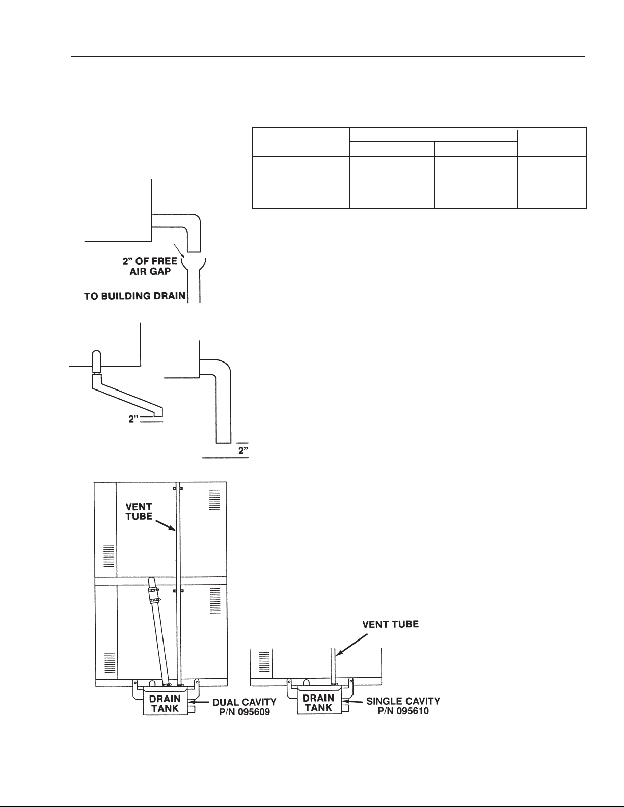
Drain Connection
Without Drain Box:
1. Drain hose cannot be connected directly to a building drain; there
cannot be any elbows or other restrictions between the oven drain and
the two inch free air gap.
2. Free Air Gap: 2” free air gap required between drain hose and building
drain.
3. Drain Line: 1-1/2” ID drain hose between oven and building drain with
a constant downward pitch.
Current Rating
1-Phase
44.9A
39.1A
3-Phase/Line
27.5A
24.1A
Power
9.3KW
9.3KW
4. Plastic pipe cannot be used for a drain line.
With Drain Box:
1. Drain hose to a building drain can be connected directly.
2. The drain box has an air vent that eliminates the need for an air gap.
3. Do not block the air vent in any way.
4. Do not attach anything to the vent tube or reduce the size of the vent
tube.
(Revised 1/02)
2-1
Page 5

CC10-E
Installation Checks
General
––––– Make sure there is no heat source within 12
inches of louvered right side of oven.
Heat Shield - Single Cavity (1) 092210
Double Cavity (2)
––––– Make sure there is a minimum six inch free
space on louvered side of oven.
––––– Make sure oven is level or pitched slightly
rearward.
––––– Check that fan is clear of packaging
materials.
––––– Check that air and water heating elements
are clear of packaging materials.
––––– Make sure boiler is clear of packaging
materials.
––––– Check that water level probes and probe
holders are clear or packaging materials.
––––– If permitted by local codes, check that hose
onnection is flexible to allow oven
c
movement for servicing.
––––– Check that water line is at least 112 inch ID.
––––– Check that water line is not putting high
stress on inlet water valve.
––––– Check that inlet water pressure is 30 to 60
PSIG.
––––– The water supply should not contain more
than 30 to 40 parts per million total
dissolved solids (TDS) and has a pH of 7.0
or higher.
Drain Connections
––––– Make sure drain plumbing connections
comply with local codes.
––––– Check that drain hose connection is flexible
to allow oven movement for servicing.
Electrical Checks
––––– Make sure oven is properly grounded per
NEC.
––––– Verify that electrical connections conform to
local code and NEC requirements.
––––– Make sure that branch circuit protection
conforms to oven specifications specified on
oven nameplate.
––––– For single-phase ovens, check that there
are no connections to terminal L3. Refer to
label above power distribution block.
–––––
––––– Check that phase selector plug is properly .
Cold Water Supply Connections
––––– Make sure plumbing connections conform
2-2
For three-phase ovens, check connections
to L1, L2, and L3. Refer to label above
power distribution block.
connected. See labels above power
distribution block and on motor bracket.
to local codes.
––––– Make sure drain line is 1-1/2 inches in
diameter.
––––– Check that drain is free vented.
––––– Make sure drain line is not directly
connected to the building drain.
––––– Check that drain line is suitable for boiling
water. Make sure PVC is not being used for
drain plumbing.
––––– Check that drain line is pitched downward.
––––– Make sure drain line is free of obstruction.
Oven Door Check
––––– Make sure door gasket is making good
contact with cavity.
––––– Check that door opens easily and freely.
–––––
Confirm that operators are leaving the door
open when unit is shut down overnight or
longer.
(Revised 1/02)
Page 6

CC10-E
Sequence Of Events
Prior to Serial Number C7439MS
perating Conditions
O
• Oven cavity below 200°F.
• Oven door closed.
• No service codes displayed in the time display window.
• There are no apparent oven operating problems.
Steam Mode (Prior to Serial Number C7439MS)
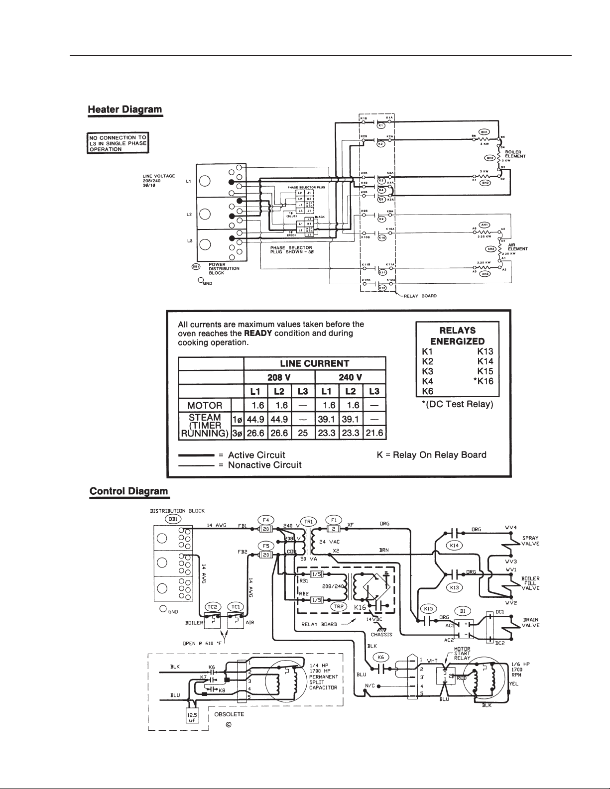
Refer to the Steam mode circuit diagrams on page 2-13 and/or the schematic
diagrams on pages 2-16 and 2-17 for the following sequence of events.
1. Relays K15 and K13 energized. Boiler drain valve closes and boiler fill valve
opens. Boiler fill begins.
2. Relay K6 energized. Fan motor turns on.
3. When water reaches low water probes, relays K1, K2, K3, and K4 energize.
High water heating elements turn on.
4. When water reaches high water probe, relay K13 de-energizes and boiler fill
valve closes.
5. When boiler water reaches “ready” temperature, relays K1, K2, K3, and K4 deenergize and water heating elements turn off.
Relay Operation Summary
1. K15 and K13 energized. (Drain and Fill)
2. K6 energized. (Fan)
3. K1 through K4 energized. (Boiler Heat)
K13 de-energized. (Fill)
4.
5. K1 through K4 de-energized. (Boiler Heat)
Combo Mode (Prior to Serial Number C7439MS)
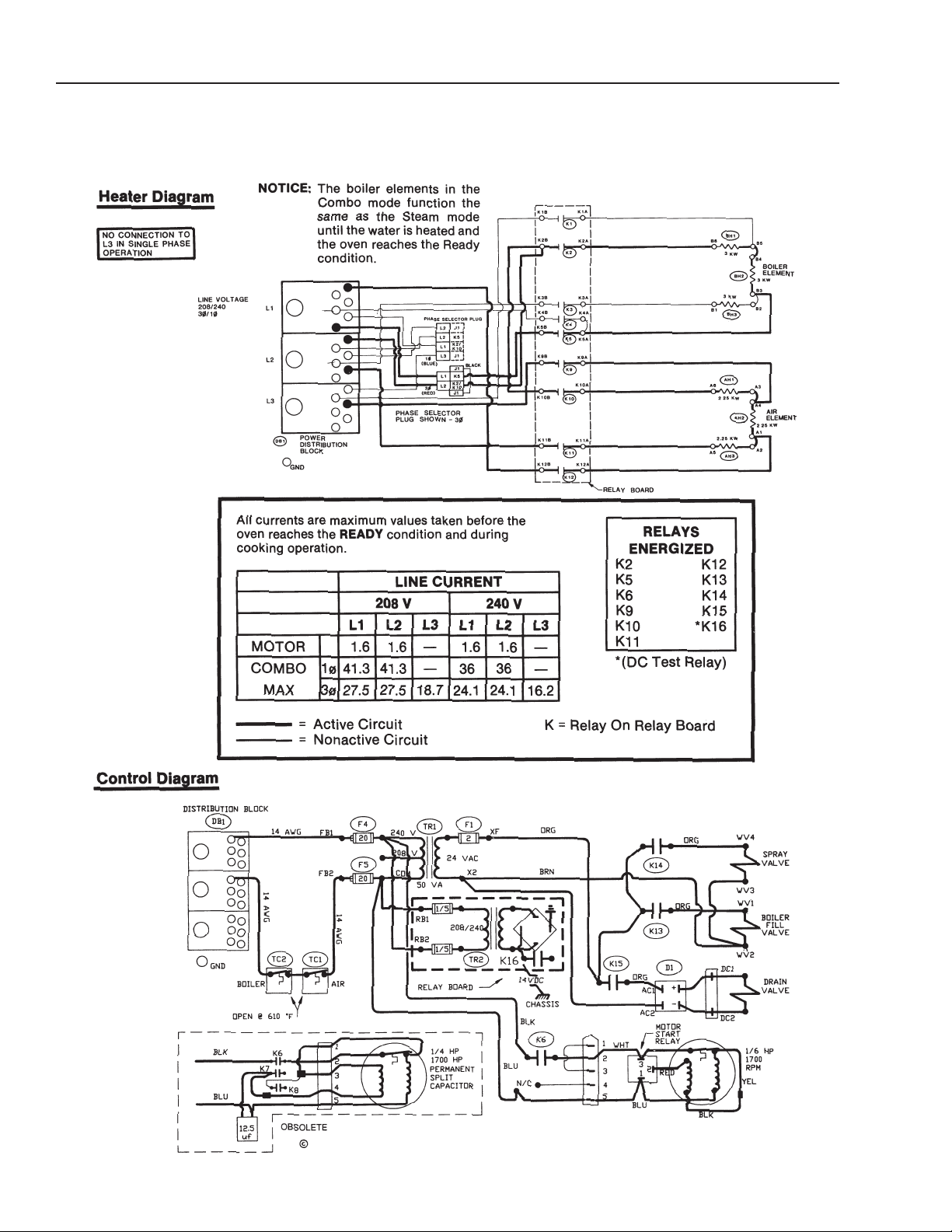
Refer to the Combo mode circuit diagrams on page 2-14 and/or the schematic
diagrams on pages 2-16 and 2-17 for the following sequence of events.
1. Relays K15 and K13 energized. Boiler drain valve closes and boiler fill valve
opens. Boiler fill begins.
2. Relay K6 energized. Fan motor turns on.
3. When water reaches low water probes, relays K1, K2, K3, and K4 energize.
High water heating elements turn on.
(Revised 1/02)
4. When water reaches high water probe, relay K13 de-energizes and boiler fill
valve closes.
2-3
Page 7

CC10-E
Sequence Of Events
Prior to Serial Number C7439MS
5. When boiler water reaches “ready” temperature, relays K1, K3, and K4
deenergize and water heating elements turn off.
. Relay K2 remains energized.
6
7. K5 energized. BH1 and BH2 are turned on.
8. K14 energized and condensate spray valve opens.
9. Relays K9, K10, K11, and K12 energize. Air heating elements turn on.
10.When oven temperature reaches the temperature set point, relays K9, K10,
K11, and K12 de-energize. Air heating elements turn off.
Relay Operation Summary
1. K15 and K13 energized. (Drain and Fill)
2. K6 energized. (Fan)
3. K1 through K4 energized. (High Water)
4. K13 de-energized. (Fill)
5. K1, K3, and K4 de-energized. K5 energized. (High Heat to Low Heat)
6. K9 through K12 energized. (High Air)
7. K9 through K12 de-energized. (High Air)
Oven Mode (Prior to Serial Number C7439MS)
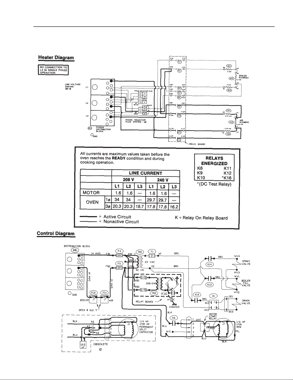
Refer to the Oven mode circuit diagrams on page 2-15 and/or the schematic
diagrams on pages 2-16 and 2-17 for the following sequence of events.
1. Relay K6 energized. Fan motor turns on.
2. Relays K9, K10, K11, and K12 energize. Air heating elements turn on.
When oven temperature reaches the temperature set point, relays K9, K10,
3.
K11, and K12 de-energize. Air heating elements turn of
Relay Operation Summary
1. K6 energized. (Fan)
f.
K9 through K12 energized. (High
2.
3. K9 through K12 de-energized. (High Air)
2-4
Air)
(Revised 1/02)
Page 8

CC10-E
Sequence Of Events
Prior to Serial Number C7439MS
Hold Mode (Prior to Serial Number C7439MS)
Refer to the schematic diagrams on pages 2-16 and 2-17 for the following
sequence of events.
NOTE: Low humidity on older panels only. When “Lo” humidity is selected there
is no water in steam generator.
1. Relays K15 and K13 energized. Boiler drain valve closes and boiler fill valve
opens. Boiler fill begins.
2. Relay K6 energized. Fan motor turns on. Fan will cycle on and off as required.
3. When water reaches low water probes, relays K1, K2, K3, and K4 energize.
4. When water reaches high water probe, relay K13 de-energizes and boiler fill
valve closes.
5. When boiler water reaches “ready” temperature, relays K1, K2,
K3, and K4 de-energize, and water heating elements turn off.
6. K14 energizes and condensate spray valve opens.
7. Relays K9, K10, K11, and K12 energize. Air heating elements turn on.
8. When oven air temperature is 10° below temperature set point, relays K10 and
K11 de-energize. Air heating elements operate at reduced power.
9. When oven temperature reaches the temperature set point, relays K9 and K12
de-energize. Air heating elements turn off.
Relay Operation Summary
K15 and K13 energized. (Drain and Fill)
1.
2. K6 energized. (Fan)
3. K1 through K4 energized. (High Water)
4. K13 de-energized. (Fill)
5. K1 through K4 de-energized. (High Water)
6. K14 energized. (Condensate Spray)
7. K9 through K12 energized. (High Air)
(Revised 1/02)
8. K10 and K11 de-energized. (Low Air)
K9 and K12 de-energized. (Air Heat)
9.
2-5
Page 9

CC10-E
Sequence Of Events
Prior to Serial Number C7439MS
Two Stage Cleaning Cycle (Prior to Serial Number C7439MS)
Refer to the schematic diagrams on pages 2-16 and 2-17 for the
ollowing sequence of events.
f
Phase 1
1. CL:50 is displayed in the time display window.
2. Relay K15 energized. Drain valve closes and boiler fills.
3. Relay K6, K7, and K8 energized. Fan motor turns on.
4. Relays K1, K2, K3, and K4 energize and water heating elements
turn on.
5. When the water temperature is approximately 150°F, relays K1, K2, K3, and
K4 de-energize.
6. Relays K1, K2, K3 and K4 energize and water heating elements turn on.
7. Relay K14 energizes and condensate spray valve opens.
8. Relay K15 de-energizes and drain valve opens.
9. Relays K1, K2, K3 and K4 de-energize and water heating elements turn off.
10. Relay K14 de-energizes and condensate spray valve closes.
Phase 2 (Oven Door Open)
11. Relay K15 energizes and drain valve closes. Boiler fills.
12. Relays K1 through K4 energize and water heating elements turn on.
13. When water temperature is approximately 150°F, relays K1 through K4
de-energize and water heating elements turn off.
14. Relays K1 through K4, and K14 energize. Water heating elements are on and
condensate spray valve opens.
Relay K15 de-energizes and boiler fill valve opens to drain boiler
15.
16. Relays K1 through K4, and K14 de-energize. The water heating elements turn
off and the condensate spray valve closes.
Relay K15 energizes and the drain valve closes.
17.
18. Relays K1 through K4, and K14 energize. Water heating elements are on and
condensate spray valve opens.
19. Relay K15 de-energizes and boiler fill valve opens to drain boiler.
The boiler fills.
.
20. Relays K1 through K4, and K14 de-energize. The water heating elements turn
off and the condensate spray valve closes.
2-6
(Revised 1/02)
Page 10

CC10-E
Sequence Of Events
After Serial Number C7439MS
Operating Conditions
Oven cavity below 200°F.
•
• Oven door closed.
• No service codes displayed in the time display window.
• There are no apparent oven operating problems.
Steam Mode (After Serial Number C7439MS)
Refer to the Steam mode circuit diagrams on page 2-13 and/or the schematic
diagrams on pages 2-16 and 2-17 for the following sequence of events.
1. Relays K15 and K13 energized. Boiler drain valve closes and boiler fill valve
opens. Boiler fill begins. Relay K9 through K12 energizes air elements.
2. Relay K6 energized. Fan motor turns on.
3. When water reaches low water probes, relays K1, K2, K3, and K4 energize.
High water heating elements turn on. Relay K9 through K12 de-energize
4. When water reaches high water probe, relay K13 de-energizes and boiler fill
valve closes.
5. When boiler water reaches “ready” temperature, relays K1, K3, and K4 deenergize and K2 remains energized. K5 energizes and the water heating
elements go to low heat. Relays K9 through K12 energize until cavity is at
200°F. Relay K9 through K12 de-energize.
Relay Operation Summary
1. K15 and K13 energized. (Drain and Fill)
2. K6 energized. (Fan)
3. K1 through K4 energized. (Boiler Heat)
4. K13 de-energized. (Fill)
K1, K3 and K4 de-energized. (Boiler Heat). K2 remains energized, K5
5.
energized, K9 through K12 energized.
6. K9 through K12 de-energized.
Combo Mode (After Serial Number C7439MS)
(Revised 1/02)
Refer to the Combo mode circuit diagrams on page 2-14 and/or the schematic
diagrams on pages 2-16 and 2-17 for the following sequence of events.
1. Relays K15 and K13 energized. Boiler drain valve closes and boiler fill valve
opens. Boiler fill begins. Relay K9 through K12 energizes air elements.
Relay K6 energized. Fan motor turns on.
2.
2-7
Page 11

CC10-E
Sequence Of Events
After Serial Number C7439MS
3. When water reaches low water probes, relays K1, K2, K3, and K4 energize.
High water heating elements turn on. Relay K9 through K12 de-energize.
4. When water reaches high water probe, relay K13 de-energizes and boiler fill
valve closes.
5. When boiler water reaches “ready” temperature, relays K1, K3, and K4
deenergize and water heating elements turn off.
6. Relay K2 remains energized.
7. K5 energized. BH1 and BH2 are turned on.
8. K14 energized and condensate spray valve opens.
9. Relays K9, K10, K11, and K12 energize. Air heating elements turn on.
10. When oven temperature reaches the temperature set point, relays K9, K10,
K11, and K12 de-energize. Air heating elements turn off.
Relay Operation Summary
1. K15 and K13 energized. (Drain and Fill)
2. K6 energized. (Fan)
3. K1 through K4 energized. (High Water)
4. K13 de-energized. (Fill)
5. K1, K3, and K4 de-energized. K5 energized. (High Heat to Low Heat)
K9 through K12 energized. (High Air)
6.
7. K9 through K12 de-energized. (High Air)
Oven Mode (After Serial Number C7439MS)
Refer to the Oven mode circuit diagrams on page 2-15 and/or the schematic
diagrams on pages 2-16 and 2-17 for the following sequence of events.
1. Relay K6 energized. Fan motor turns on.
2. Relays K9, K10, K11, and K12 energize. Air heating elements turn on.
3. When oven air temperature is 5° below temperature set point, relays K10 and
1 de-energize.
K1
4. When oven temperature reaches the temperature set point, relays K9 and K12
de-energize. Air heating elements turn of
2-8
Air heating elements operate at reduced power
f.
.
(Revised 1/02)
Page 12

CC10-E
Sequence Of Events
After Serial Number C7439MS
Relay Operation Summary
1. K6 energized. (Fan)
2. K9 through K12 energized. (High Air)
3. K10 and K11 de-energized.
4. K9 and K12 de-energized. (High Air)
Hold Mode (After Serial Number C7439MS)
Refer to the schematic diagrams on pages 2-16 and 2-17 for the following
sequence of events.
NOTE: Low humidity on older panels only. When “Lo” humidity is selected there
is no water in steam generator.
1. Relay K6 energized. Fan motor turns on. Fan will cycle on and off as required.
2. Relays K9, K10, K11, and K12 energize. Air heating elements turn on.
3. When oven air temperature is 5° below temperature set point, relays K10 and
K11 de-energize. Air heating elements operate at reduced power.
4. When oven temperature reaches the temperature set point, relays K9 and K12
de-energize. Air heating elements turn off.
Relay Operation Summary
1. K15 and K13 energized. (Drain and Fill)
2. K6 energized. (Fan)
3. K1 through K4 energized. (High Water)
4. K13 de-energized. (Fill)
5. K1 through K4 de-energized. (High Water)
6. K14 energized. (Condensate Spray)
7. K9 through K12 energized. (High Air)
8. K10 and K11 de-energized. (Low Air)
(Revised 1/02)
9. K9 and K12 de-energized. (Air Heat)
2-9
Page 13

CC10-E
Sequence Of Events
After Serial Number C7439MS
Two Stage Cleaning Cycle (After Serial Number C7439MS)
Refer to the schematic diagrams on pages 2-16 and 2-17 for the following
equence of events.
s
Phase 1
1. C1 is displayed in the time display window. Spray degreaser around the cavity
and press “START.”
2. Relay K15 energized. Drain valve closes and boiler fills.
3. Relay K6 energized. Fan motor turns on.
4. Relays K1, K2, K3, and K4 energize and water heating elements turn on.
5. When the water temperature is approximately 150°F, relays K1, K2, K3, and
K4 de-energize.
6. Relays K1, K2, K3 and K4 energize and water heating elements turn on.
7. Relay K14 energizes and condensate spray valve opens.
CL:50 is displayed in the time display window.
8. Relay K15 de-energizes and drain valve opens.
9. Relays K1, K2, K3 and K4 de-energize and water heating elements turn off.
10. Relay K14 de-energizes and condensate spray valve closes.
in the time display window.
Phase 2 (Oven Door Open) - add delimer in the boiler.
11. Relay K15 energizes and drain valve closes. Boiler fills.
12. Relays K1 through K4 energize and water heating elements turn on.
13. When water temperature is approximately 150°F, relays K1 through K4
de-energize and water heating elements turn off.
Relays K1 through K4, and K14 energize. W
14.
condensate spray valve opens.
15. Relay K15 de-energizes and boiler fill valve opens to drain boiler.
16. Relays K1 through K4, and K14 de-energize. The water heating elements turn
off and the condensate spray valve closes.
17. Relay K15 energizes and the drain valve closes. The boiler fills.
Relays K1 through K4, and K14 energize. W
18.
condensate spray valve opens.
ater heating elements are on and
ater heating elements are on and
C2 is displayed
19. Relay K15 de-energizes and boiler fill valve opens to drain boiler.
20. Relays K1 through K4, and K14 de-energize.
off and the condensate spray valve closes.
2-10
The water heating elements turn
(Revised 1/02)
Page 14

CC10-E
Operation
Prior to Serial Number C7439MS
The model CC10-E is a combination steamer-oven with a stainless steel cooking
chamber, a steam generator, and electronic circuitry for controlling unit operation.
It can operate from a single-phase or three-phase, 208 or 240 volt, 60 hertz power
source.
It can function as a convection oven, a self-contained pressureless steamer, or as
a combination oven-steamer. Mode of operation is controlled by the control panel
touch pad switches.
Replaceable electric (air) elements and the blower fan provide oven temperatures
up to a maximum of 575°F.
Replaceable heating elements are used to generate steam. The steam generator
cavities are adjacent to the cooking compartment and easily accessible. All of the
condensate leaves the oven through the cavity drain. When the unit is turned off,
or the oven cooking mode is selected, the steam generator cavity automatically
drains.
The control panel is a solid-state controller. The solid-state circuitry has a selfdiagnostic program to assist you in troubleshooting, and a pre-programmed
cleaning cycle to assist the operator in daily cleaning.
The door interlock switch operates to turn off the fan and oven elements when the
door is opened. The boiler elements go to low heat.
The electrical circuits that are active for the three operating modes are shown in
the following illustrations.
(Revised 1/02)
2-11
Page 15

CC10-E
Operation
After Serial Number C7439MS
The model CC10-E is a combination steamer-oven with a stainless steel cooking
chamber, a steam generator, and electronic circuitry for controlling unit operation.
It can operate from a single-phase or three-phase, 208 or 240 volt, 60 hertz power
ource.
s
It can function as a convection oven, a self-contained pressureless steamer, or as
a combination oven-steamer. Mode of operation is controlled by the control panel
touch pad switches. Hold mode is optional.
Replaceable electric (air) elements and the blower fan provide oven temperatures
up to a maximum of 575°F.
Replaceable heating elements are used to generate steam. The steam generator
cavities are adjacent to the cooking compartment and easily accessible. All of the
condensate leaves the oven through the cavity drain. When the unit is turned off
the steam generator automatically drains. When the oven cooking mode is
selected, the steam generator cavity automatically drains. When no mode is
selected the steam generator fills and water is held at 160°F.
The control panel is a solid-state controller. The solid-state circuitry has a selfdiagnostic program to assist you in troubleshooting, and a pre-programmed
cleaning cycle to assist the operator in daily cleaning.
The door interlock switch operates to turn off the fan and oven/ steamer elements
when the door is opened.
The electrical circuits that are active for the three operating modes are shown in
the following illustrations.
2-12
2-12
(Revised 1/02)
Page 16
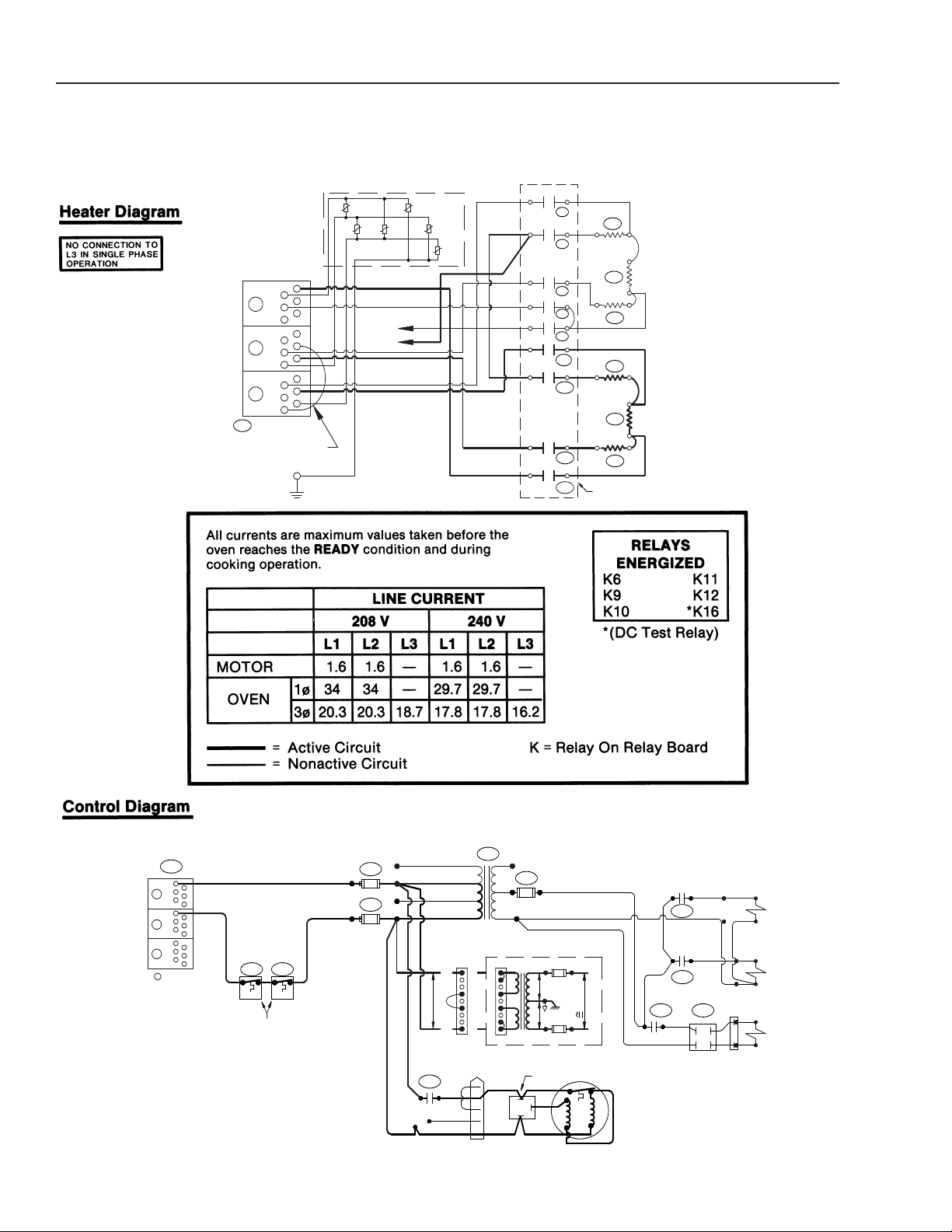
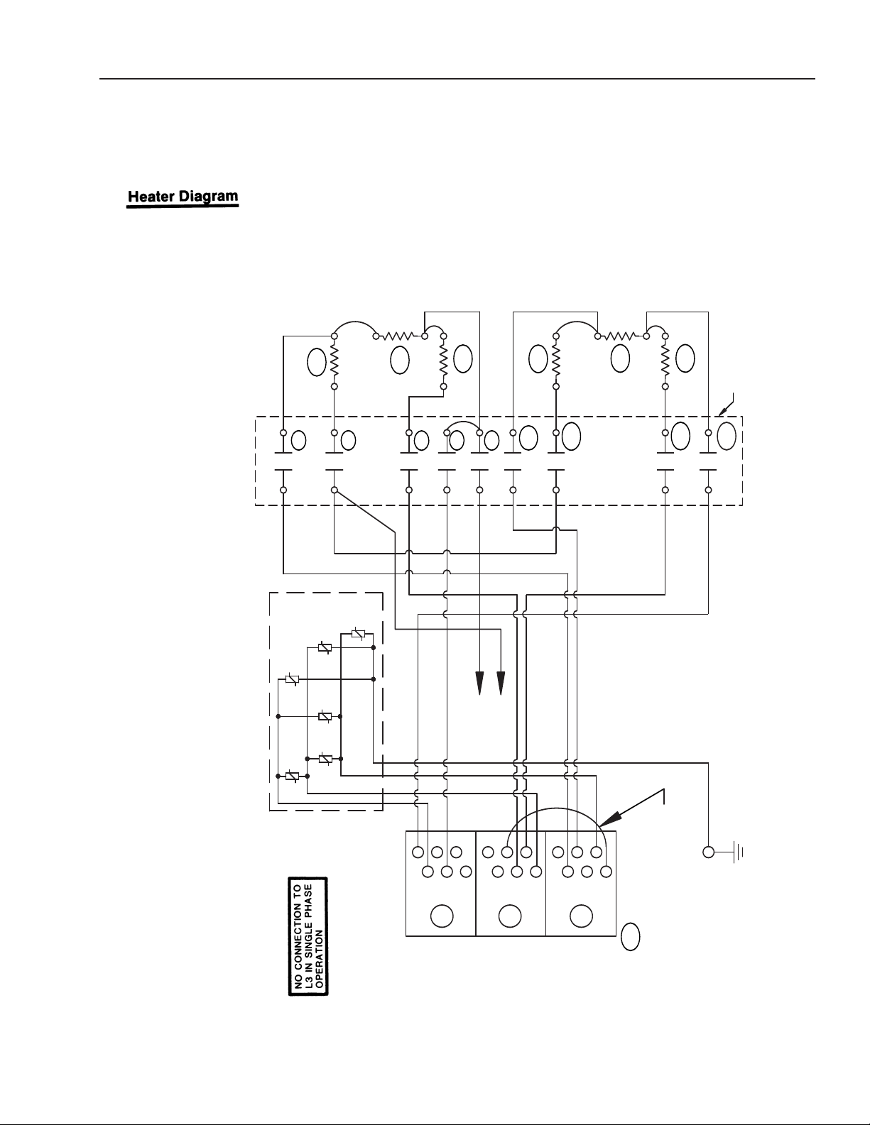
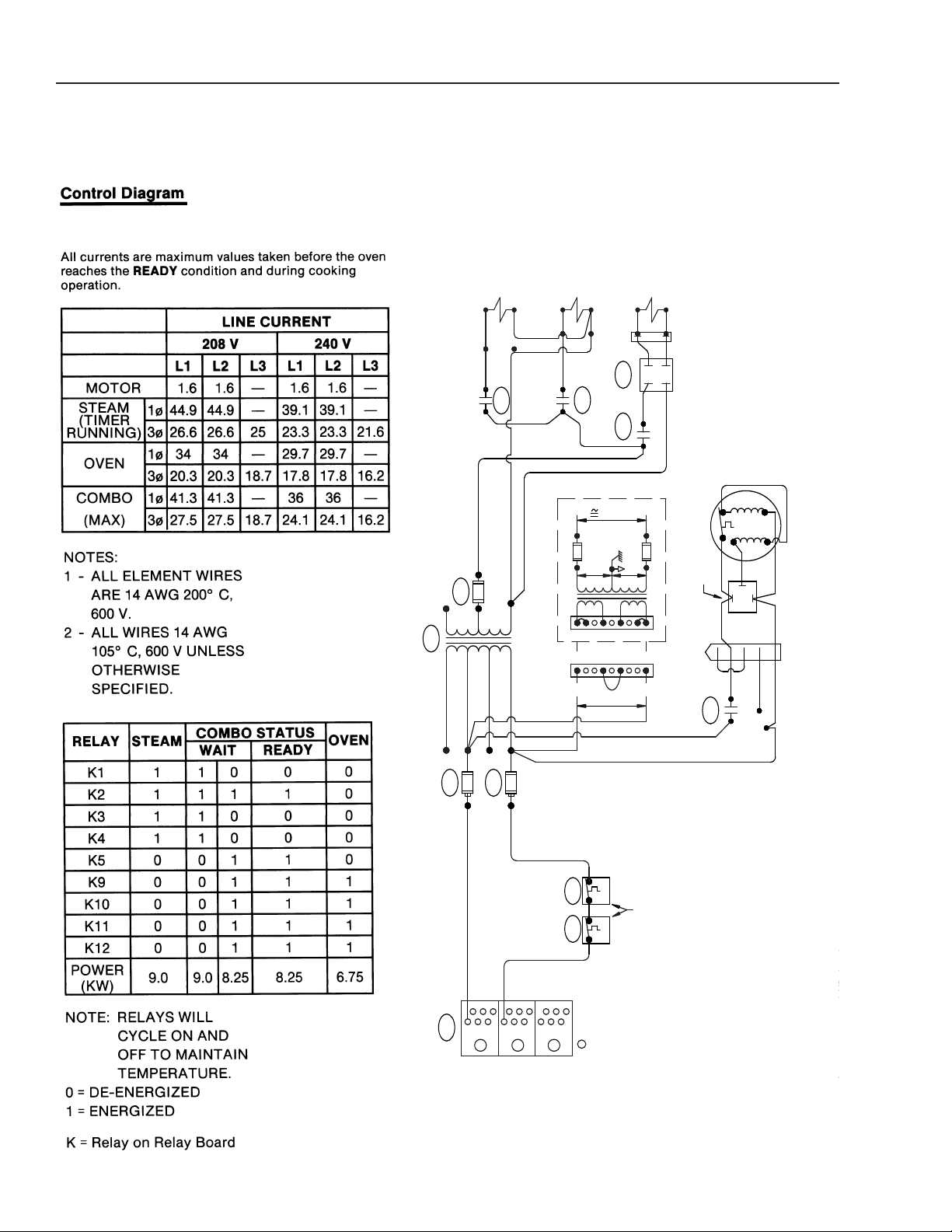
CC10-E
Operation
Prior to Serial Number C7439MS
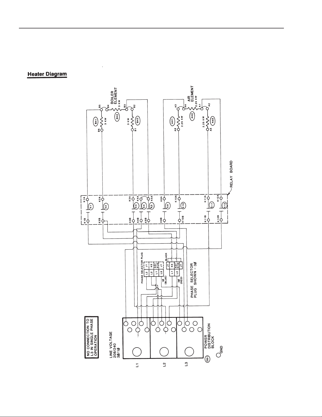
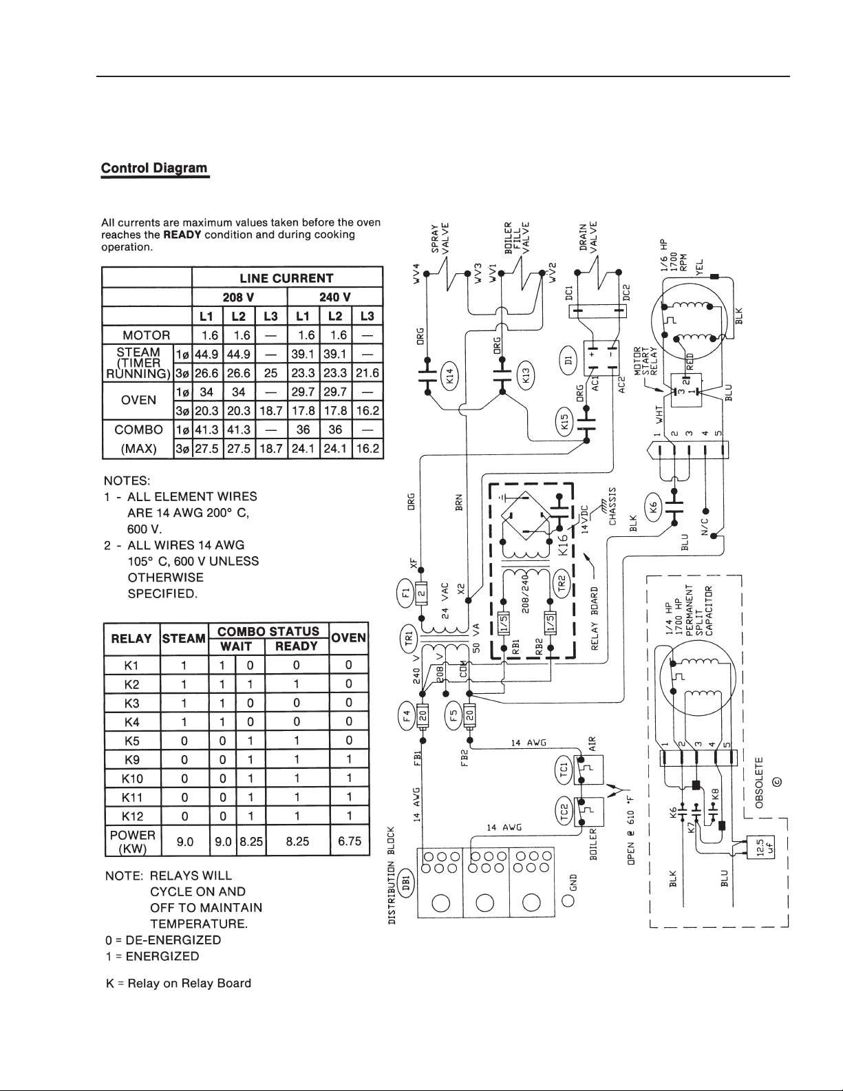
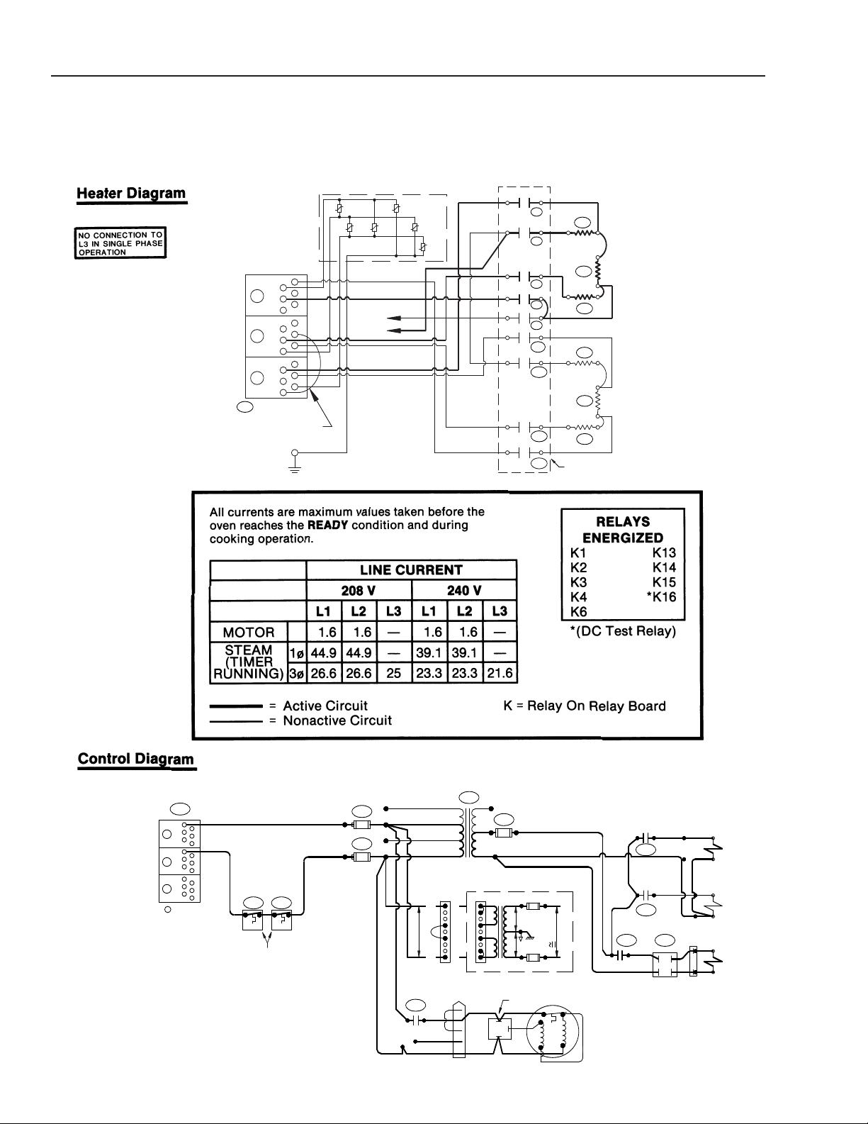
team Mode Circuit
S
(Revised 1/02)
2-13
Page 17
CC10-E
Operation
Prior to Serial Number C7439MS
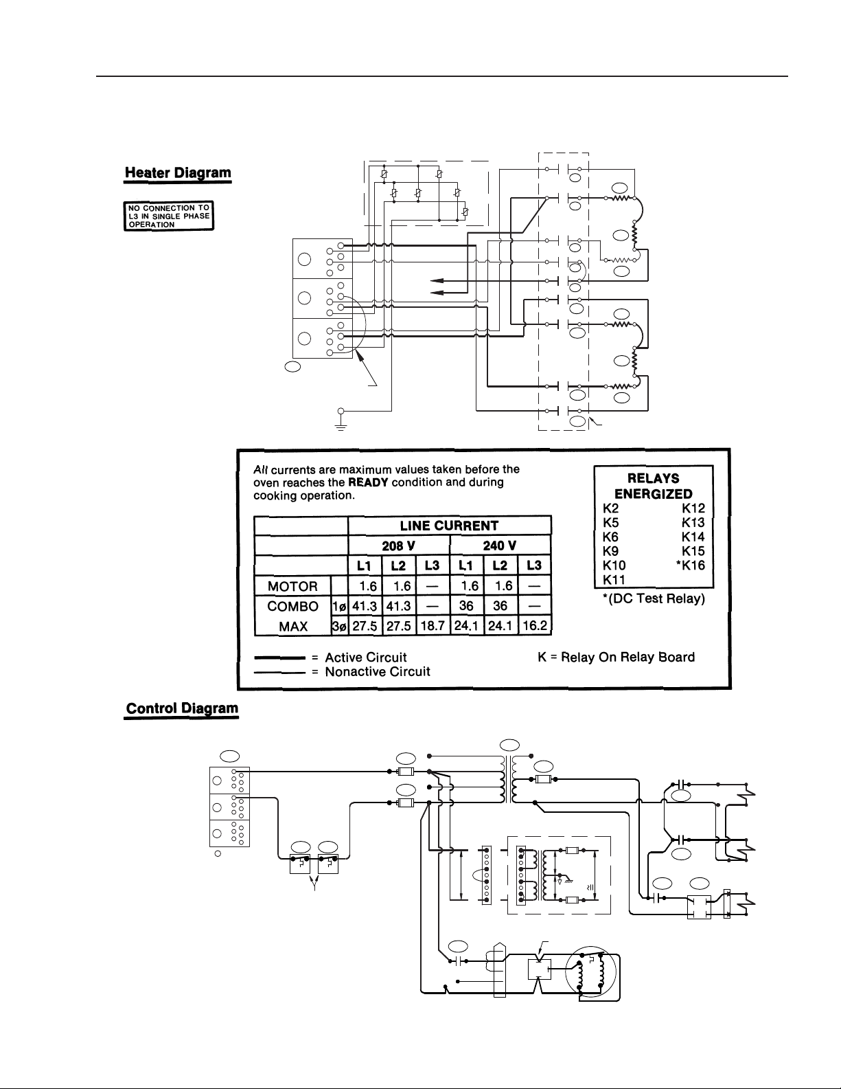
Combo Mode Circuit
2-142-142-14
(Revised 1/02)
Page 18
CC10-E
Operation
Prior to Serial Number C7439MS
ven Mode Circuit
O
(Revised 1/02)
2-15
Page 19
CC10-E
Electrical Diagrams
Prior to Serial Number C7439MS
Schematic Diagrams for CC10-E
2-162-16
(Revised 1/02)
Page 20
CC10-E
Electrical Diagrams
Prior to Serial Number C7439MS
chematic Diagrams for CC10-E
S
(Revised 1/02)
2-172-17
Page 21
CC10-E
GND
D
B1
L3
BLOCK
D
ISTRIBUTION
POWER
208/220/240V
1ø, 3ø
L2
LINE VOLTAGE
L1
-2
MOV
-4
-6
M
OV
MOV
-1
MOV
-3
-5
MOV
MOV
MOV BOARD
A6
ELEMENT
AIR
K12B
K11B
K10B
AH3
K11
RELAY BOARD
K12
K12A
2.25 KW
2.25 KW
K
11A
A5
K10
K
10A
A1
2.25 KW
A2
AH2
A3
A4
ELEMENT
BOILER
K
5B
K9B
K
4B
K
3B
K2B
K1B
BH2
3 KW
3 KW
K5A
K
9A
K9
K5
K4A
K4
K3
B1
AH1
B
3
B2
BH3
K
3A
K
2
K1
K2A
K1A
B6
B4
3 KW
B5
BH1
G
ND
12AWG
(1ph ONLY)
Xph
Yph
SEE
TABLE
DISTRIBUTION BLOCK
OPEN @ 610° F
BOILER
TC2
DB1
14 AWG
AIR
TC1
FB2-A
FB1-A
F4
FB2-B
F5
20
20
FB1-B
24 VAC
50 VA
COM
200/208V
TR1
X2
2
F1
XF
1700 RPM
1/6 HP
BLU
AC2
N/C
BLU
K6
BLK
2
5
3
4
WHT
1
BLK
RED
3
1
2
-
RELAY
START
MOTOR
YEL
DC2
SPRAY
VALVE
BOILER
K14
ORG
K13
AC1
K15
BRN
BRN
ORG
+
D1
ORG
DC1
DRAIN
VALVE
WV2
WV1
FILL
VALVE
ORG
WV3
WV4
L2
L1
L3
GND
208V-240V
A
B
14VAC
RELAY BOARD
14VAC
3
J4
1
21
64
654
9
987
POWER TO
1.25 AMP
C
28VAC
D
RELAY BOARD
1.25 AMP
14 AWG
14 AWG
220/230/240V
440/460/480V
Electrical Diagrams
After Serial Number C7439MS
Steam Mode Circuit
2-18
(Revised 1/02)
Page 22
GND
DB1
L
3
BLOCK
DISTRIBUTION
POWER
208/220/240V
1ø, 3ø
L2
LINE VOLTAGE
L1
-
2
MOV
-4
-6
MOV
MOV
-1
MOV
-3
-5
MOV
MOV
MOV BOARD
A6
ELEMENT
AIR
K12B
K11B
K
10B
AH3
K11
RELAY BOARD
K12
K12A
2.25 KW
2.25 KW
K11A
A
5
K10
K10A
A
1
2.25 KW
A
2
AH2
A3
A
4
ELEMENT
BOILER
K5B
K
9B
K4B
K3B
K2B
K1B
BH2
3 KW
3 KW
K
5A
K9A
K9
K5
K4A
K
4
K3
B
1
AH1
B3
B2
BH3
K3A
K2
K
1
K2A
K1A
B
6
B
4
3 KW
B
5
B
H1
GND
12AWG
(1ph ONLY)
Xph
Yph
SEE
TABLE
DISTRIBUTION BLOCK
OPEN @ 610° F
BOILER
TC2
DB1
14 AWG
AIR
TC1
FB2-A
FB1-A
F4
FB2-B
F5
20
20
FB1-B
24 VAC
50 VA
COM
200/208V
TR1
X2
2
F1
XF
1700 RPM
1/6 HP
BLU
AC2
N/C
BLU
K6
BLK
2
5
3
4
WHT
1
BLK
RED
3
1
2
-
RELAY
START
MOTOR
YEL
DC2
SPRAY
VALVE
BOILER
K14
ORG
K13
AC1
K15
BRN
BRN
ORG
+
D1
ORG
DC1
DRAIN
VALVE
WV2
WV1
FILL
VALVE
ORG
WV3
WV4
L2
L1
L3
GND
208V-240V
A
B
14VAC
RELAY BOARD
14VAC
3
J4
1
21
64
654
9
987
POWER TO
1.25 AMP
C
28VAC
D
RELAY BOARD
1.25 AMP
14 AWG
14 AWG
220/230/240V
440/460/480V
CC10-E
Electrical Diagrams
After Serial Number C7439MS
ombo Mode Circuit
C
(Revised 1/02)
2-19
Page 23
CC10-E
GND
DB1
L3
BLOCK
DISTRIBUTION
POWER
208/220/240V
1ø, 3ø
L2
LINE VOLTAGE
L1
-2
MOV
-4
-6
MOV
MOV
-1
MOV
-3
-5
MOV
MOV
MOV BOARD
A
6
ELEMENT
AIR
K12B
K
11B
K
10B
AH3
K11
RELAY BOARD
K12
K
12A
2.25 KW
2.25 KW
K11A
A5
K10
K10A
A1
2.25 KW
A2
A
H2
A
3
A4
ELEMENT
BOILER
K5B
K
9B
K4B
K3B
K
2B
K1B
BH2
3 KW
3 KW
K5A
K9A
K9
K
5
K4A
K4
K3
B1
AH1
B3
B
2
BH3
K3A
K2
K1
K
2A
K1A
B
6
B4
3 KW
B
5
BH1
GND
12AWG
(1ph ONLY)
X
ph
Yph
SEE
TABLE
DISTRIBUTION BLOCK
OPEN @ 610° F
BOILER
TC2
DB1
14 AWG
AIR
TC1
FB2-A
FB1-A
F4
FB2-B
F5
20
20
FB1-B
24 VAC
50 VA
COM
200/208V
TR1
X2
2
F1
XF
1700 RPM
1/6 HP
BLU
AC2
N/C
BLU
K6
BLK
2
5
3
4
WHT
1
BLK
RED
3
1
2
-
RELAY
START
MOTOR
YEL
DC2
SPRAY
VALVE
BOILER
K14
ORG
K13
AC1
K15
BRN
BRN
ORG
+
D1
ORG
DC1
DRAIN
VALVE
WV2
WV1
FILL
VALVE
ORG
WV3
WV4
L2
L1
L3
GND
208V-240V
A
B
14VAC
RELAY BOARD
14VAC
3
J4
1
21
64
654
9
987
POWER TO
1.25 AMP
C
28VAC
D
RELAY BOARD
1.25 AMP
14 AWG
14 AWG
220/230/240V
440/460/480V
Electrical Diagrams
After Serial Number C7439MS
Oven Mode Circuit
2-20
(Revised 1/02)
Page 24
CC10-E
GND
DB1
L3
BLOCK
DISTRIBUTION
POWER
208/220/240V
1ø, 3ø
L2
LINE VOLTAGE
L1
-2
MOV
-4
-6
MOV
MOV
-1
MOV
-3
-5
MOV
MOV
MOV BOARD
A6
ELEMENT
AIR
K12B
K11B
K10B
AH3
K11
RELAY BOARD
K12
K12A
2.25 KW
2.25 KW
K11A
A5
K10
K10A
A1
2.25 KW
A2
AH2
A3
A4
ELEMENT
BOILER
K5B
K9B
K4B
K3B
K2B
K1B
BH2
3 KW
3 KW
K5A
K9A
K9
K5
K4A
K4
K3
B1
AH1
B3
B2
BH3
K3A
K2
K1
K2A
K1A
B6
B4
3 KW
B5
BH1
GND
12AWG
(1ph ONLY)
Xph
Yph
SEE
TABLE
Electrical Diagrams
After Serial Number C7439MS
Schematic Diagrams for CC10-E
(Revised 1/02)
2-21
Page 25
CC10-E
DISTRIBUTION BLOCK
OPEN @ 610° F
BOILER
TC2
DB1
14 AWG
AIR
TC1
FB2-A
FB1-A
F4
FB2-B
F5
20
20
FB1-B
24 VAC
50 VA
COM
200/208V
TR1
X2
2
F1
XF
1700 RPM
1/6 HP
BLU
AC2
N/C
BLU
K6
BLK
253
4
WHT
1
BLK
RED
3
1
2
-
RELAY
START
MOTOR
YEL
DC2
SPRAY
VALVE
BOILER
K14
ORG
K13
AC1
K15
BRN
BRN
ORG
+
D1
ORG
DC1
DRAIN
VALVE
WV2
WV1
FILL
VALVE
ORG
WV3
WV4
L2
L1
L3
GND
208V-240V
A
B
14VAC
RELAY BOARD
1
4VAC
3
J4
1
21
64
654
9
987
P
OWER TO
1.25 AMP
C
28VAC
D
RELAY BOARD
1.25 AMP
14 AWG
14 AWG
220/230/240V
440/460/480V
Electrical Diagrams
After Serial Number C7439MS
chematic Diagrams for CC10-E
S
2-22
(Revised 1/02)
Page 26
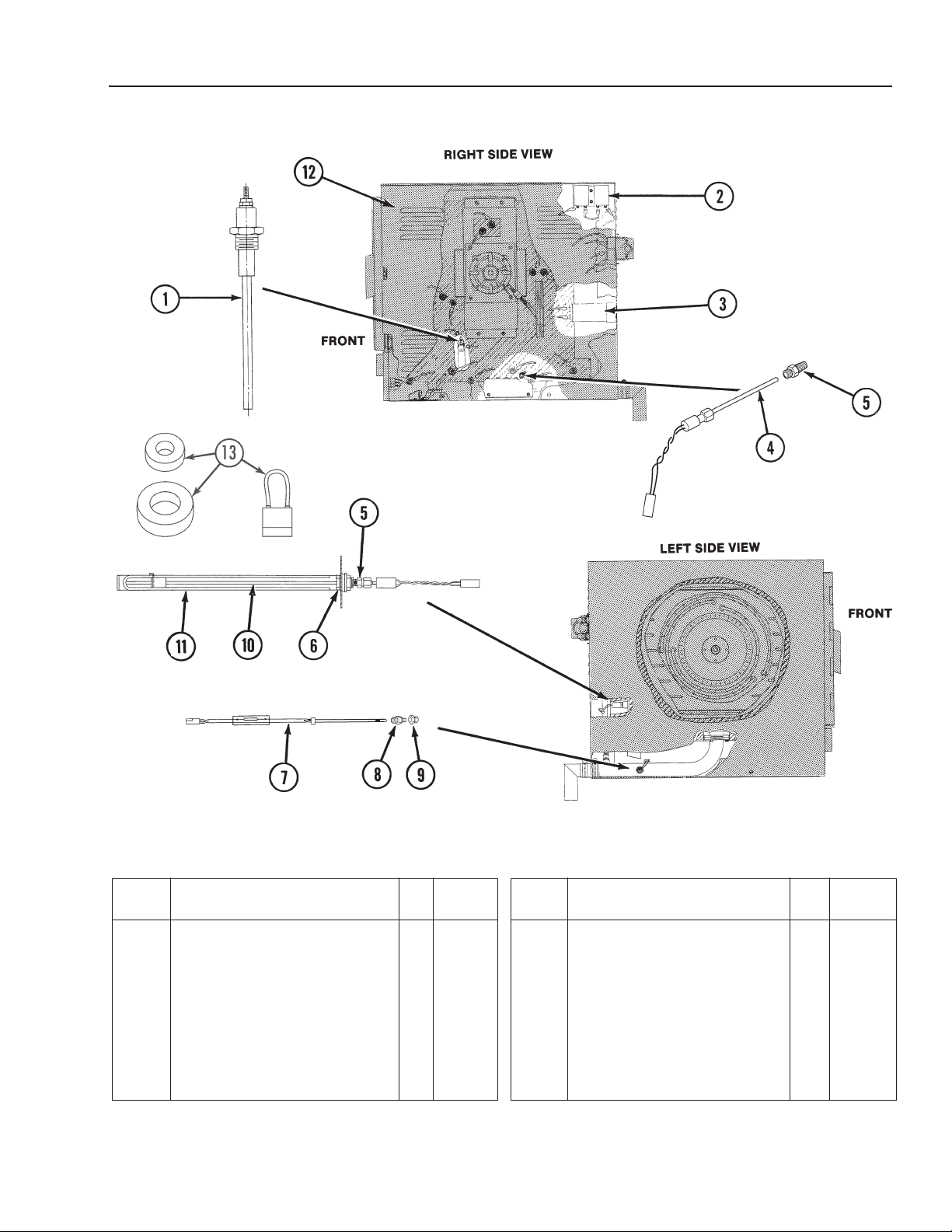
CC10-E
Parts List
Item Description Qty.
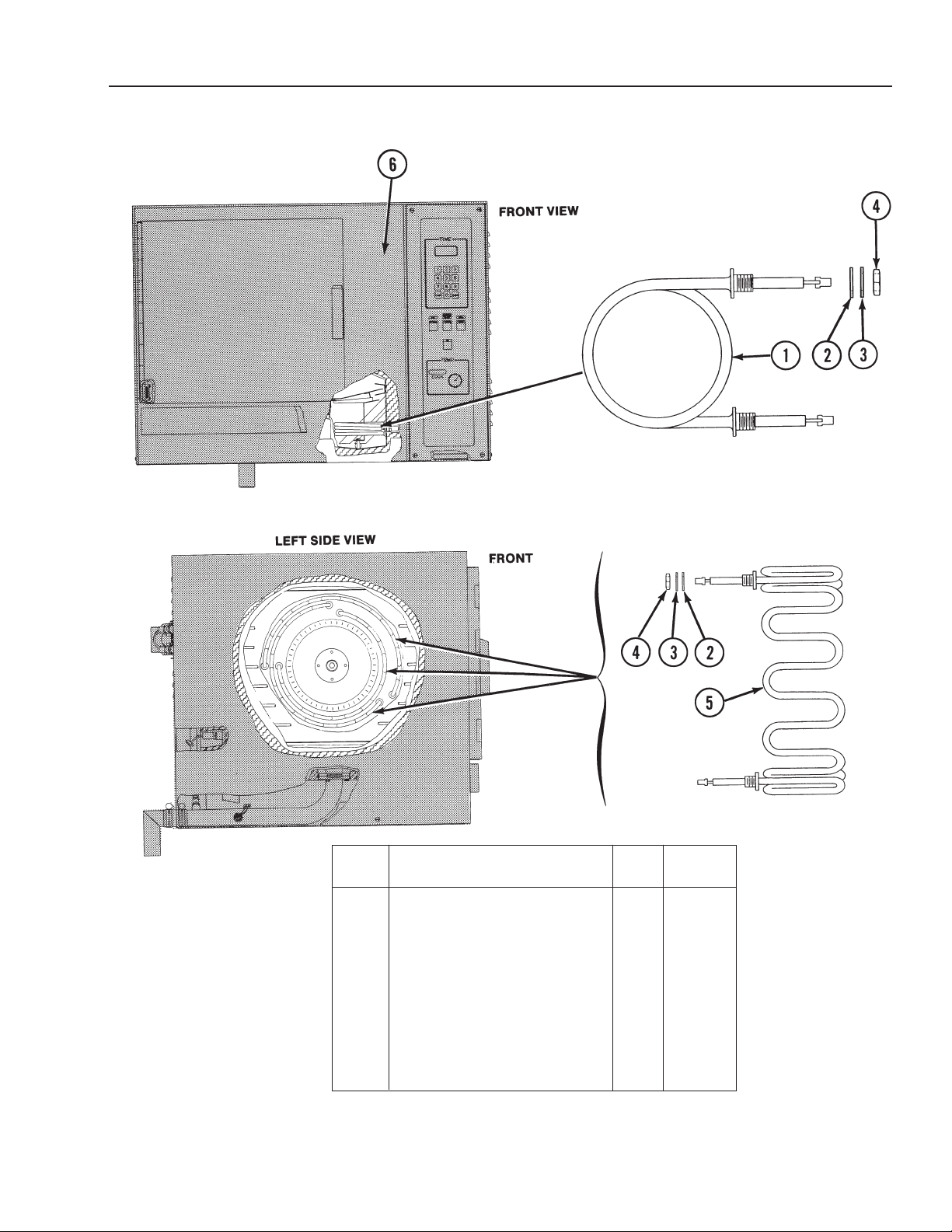
1 Probe, Water . . . . . . . . . . . . . . 2 070178
2 Thermostat . . . . . . . . . . . . . . . . 2 071499
3 Capacitor . . . . . . . . . . . . . . . . . 1 071291
4 Kit, Boiler Temperature
Probe . . . . . . . . . . . . . . . . . . . . 1 077804
5 Fitting, Male Brass . . . . . . . . . . 2 071217
6 Fitting S.S. . . . . . . . . . . . . . . . . 1 071231
†7 Kit, Drain Temperature
Probe . . . . . . . . . . . . . . . . . . . 1 077805
(Revised 1/02)
FIGURE 1
Part
No.
Figure 1. Sensors
Item Description Qty.
8 Connector, Male Brass . . . . . . 1 071251
9 Bushing Teflon . . . . . . . . . . . . 1 072163
10 Kit, Air Temperature
11 Air Probe Guard . . . . . . . . . . . 1 074827
12 Right Side Louvered Cover . . 1 070468
13 EMI Kit . . . . . . . . . . . . . . . . . . 1 118830
* Air & Drain Probe Harness . . 1 073272
* Water Probe Harness . . . . . . . 1 073268
* Not Shown† Not used on ovens after serial number C7439MS-electric
Part
No.
Probe . . . . . . . . . . . . . . . . . . 1 077803
2-23
2-23
Page 27
CC10-E
Parts List
2-24
Item Description Qty.
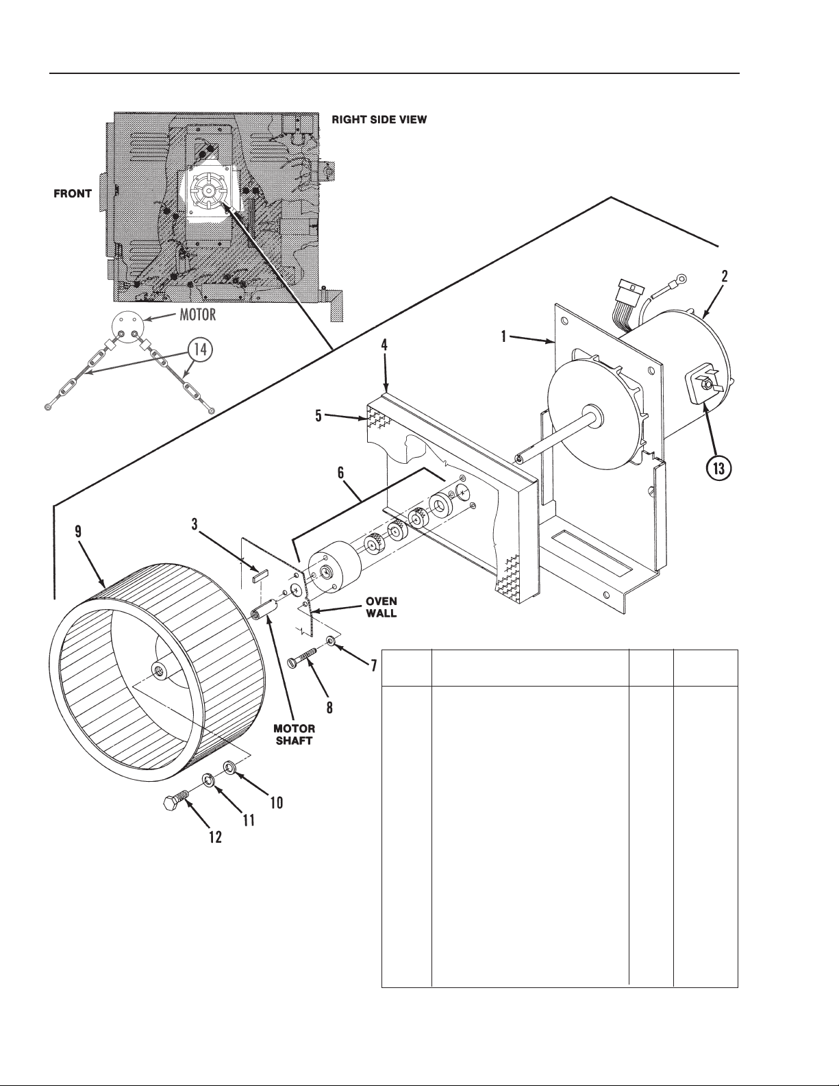
1 Bracket Assy. . . . . . . . . . . . . . 1 070100
2 Motor & Heat Slinger Assy.
3 Key, 1/8’ Square 303 S.S. . . . 1 071288
4 Insulation Retainer Assy. . . . . 1 071228
5 Insulation Nut Plate . . . . . . . . 1 069770
6 Motor Seal Assy. . . . . . . . . . . 1 071299
7 Washer, Fiber . . . . . . . . . . . . 3 071300
8 Screw, Truss Head S.S. . . . . 3 081698
9 Blower Wheel Assembly . . . . 1 074227
10 Washer, Flat . . . . . . . . . . . . . 1 059228
11 Washer, Lock . . . . . . . . . . . . 1 05656
12 Screw, Hex Head Cap S.S. . . 1 05613
13 Motor Start Relay . . . . . . . . . 1 077826
14 Kit Fan Isolator . . . . . . . . . . . 1 098684
Figure 3. Fan and Motor
Part
No.
- 280V/240V . . . . . . . . . . . . . 1 078802
• Washer Seal Housing . . . . . 1 070458
• Packing . . . . . . . . . . . . . . . . 3 070459
• Motor shaft Housing Seal . . 1 070457
(Revised 1/02)
Page 28
CC10-E
Parts List
(Revised 5/95)
Item Description Qty.
1 Water Heating Element -
208V . . . . . . . . . . . . . . . . . . . 3 070200
1 Water Heating Element -
240V . . . . . . . . . . . . . . . . . . 3 072112
2 • Fiber Washer . . . . . . . . . . . 14 072183
3 • Washer . . . . . . . . . . . . . . . . 14 *
4 • Nut . . . . . . . . . . . . . . . . . . . 14 *
5 Air Heating Element -
208V . . . . . . . . . . . . . . . . . . 3 070196
5 Air Heating Element -
240V . . . . . . . . . . . . . . . . . . 3 072111
6 Front Panel . . . . . . . . . . . . . . . 1 070472
* Supplied with element.
Figure 3. Heating Elements
Part
No.
2-25
Page 29
CC10-E
Parts List
2-26
Part
Item Description Qty.
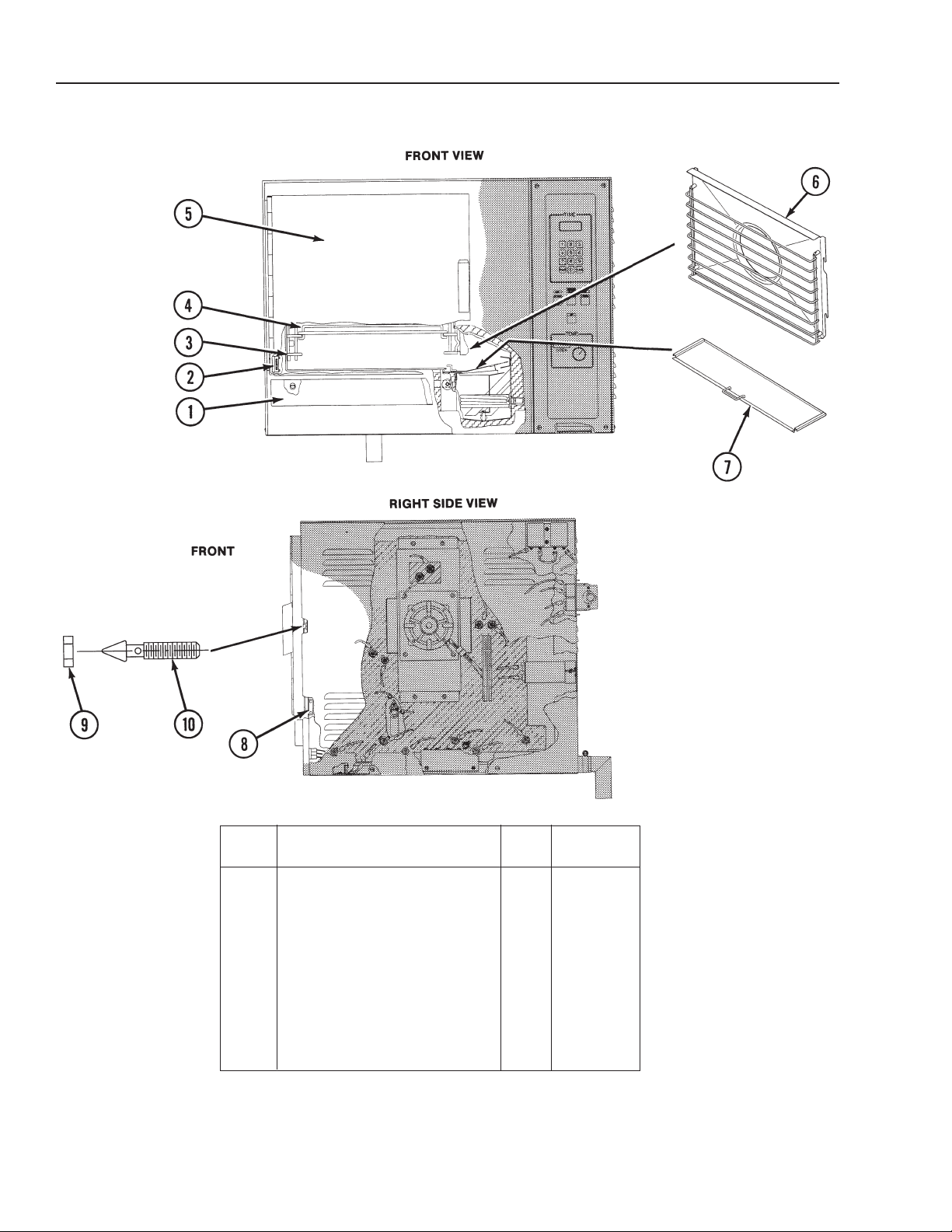
1 Drip Tray . . . . . . . . . . . . . . . . . 1 070471
2 Left Side Door Switch . . . . . . 1 078903
3 Left Side Rack . . . . . . . . . . . . 1 070180
4 Middle Rack . . . . . . . . . . . . . . 4 069764
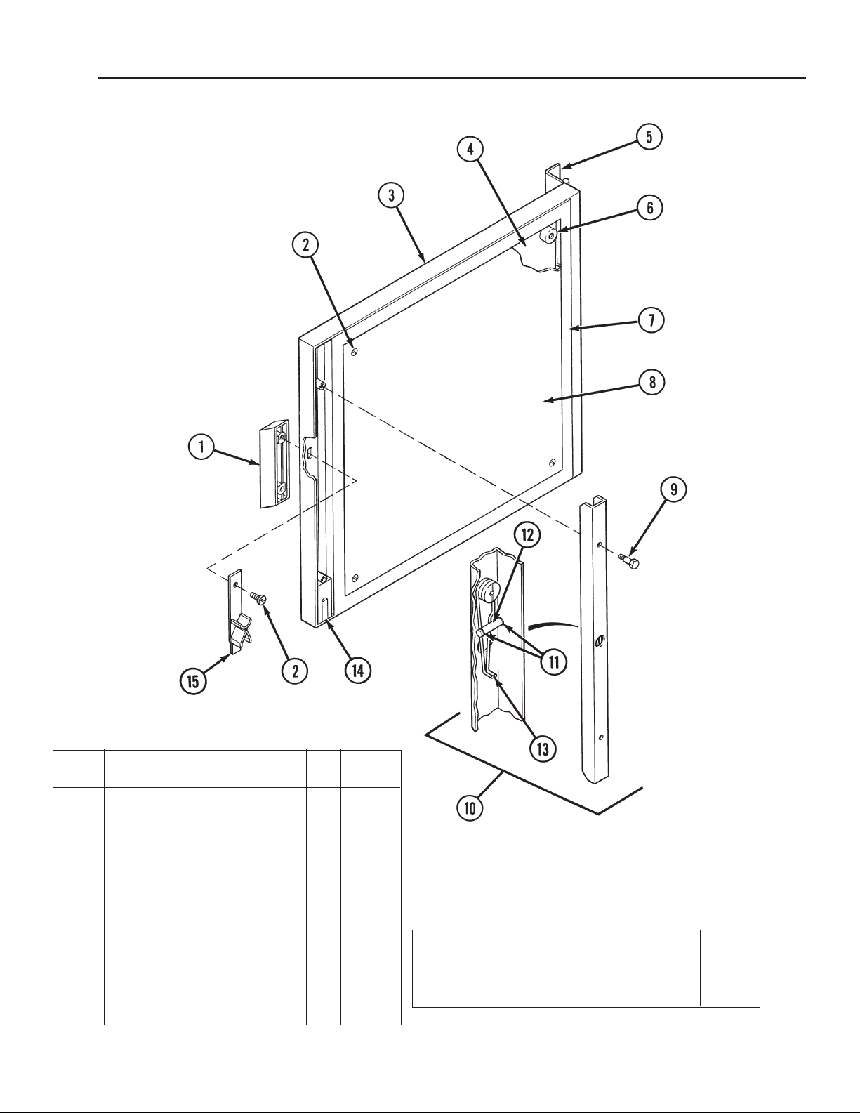
5 Door Assembly . . . . . . . . . . . . 1 See Fig. 7
6 Shroud Assembly . . . . . . . . . . 1 078920
7 Baffle Assembly Cover . . . . . . 1 070165
8 Right Side Door Switch . . . . . 1 078904
9 Door Pin Locking Nut . . . . . . . 1 003823
10 Door Latch Pin . . . . . . . . . . . . 1 078914
Figure 4. Doors, Racks and Tray
No.
(Revised 5/96)
Page 30
CC10-E
Parts List
(Revised 1/02)
Item Description Qty.
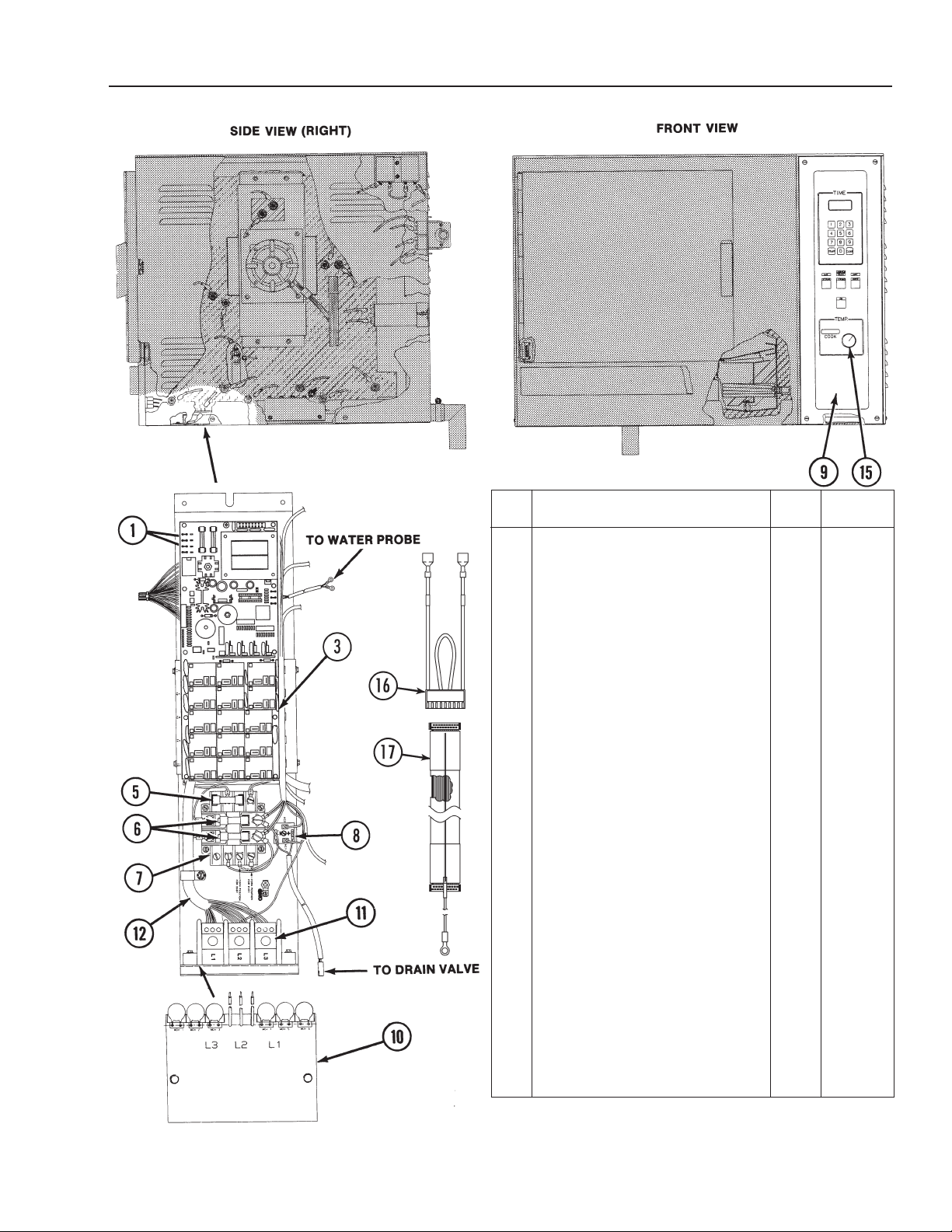
1 Fuse, 0.2 Amp., Slow Blow . . . . . . . 2 073271
Prior to Serial No. C7439MS
3 Relay Board Retrofit Kit . . . . . . . . . . 1 070184
Cook Only . . . . . . . . . . . . . . . . . . . . 1 112980
Cook
annd Hold . . . . . . . . . . . . . . . . 1 112988
Starting at Serial No. C7439MS
3 Relay
5 Fuse, 2 Amp . . . . . . . . . . . . . . . . . . . 1 071488
6 Fuse, 20 Amp . . . . . . . . . . . . . . . . . . 3 071489
7 Transformer . . . . . . . . . . . . . . . . . . . 1 071490
8 Bridge Rectifier . . . . . . . . . . . . . . . . 1 071487
9* Control Panel . . . . . . . . . . . . . . . . . .
+ Cook Only . . . . . . . . . . . . . . . . . . . . 1 112960
+
*+ Top, Cook Only . . . . . . . . . . . . . . . . 1 1
*+ Bottom, Cook Only . . . . . . . . . . . . . . 1 112960
*+ Top, Cook and Hold . . . . . . . . . . . . . 1 112961
*+ Bottom, Cook and Hold . . . . . . . . . . 1 112961
+ EPROM . . . . . . . . . . . . . . . . . . . . . . 1 112954
10 Surge Suppressor, 208/240V . . . . . . 1 098703
11 Terminal Block . . . . . . . . . . . . . . . . . 1 070185
12 Harness Line Side . . . . . . . . . . . . . . 1 072101
13 Harness Heater Side . . . . . . . . . . . . 1 072187
14 Harness Drain and Air Probe . . . . . . 1 073272
15 Control Panel Knob . . . . . . . . . . . . . 1 073430
16 Voltage Plug . . . . . . . . . . . . . . . . . . . 1 106826
17 Flexible Cable with Grounded Shield 1 114423
* Change the mounting frame with the old panel.
+ EPROM must be ordered with control panel.
Board . . . . . . . . . . . . . . . . . . 1 120718
Prior To Serial No. C7439MS
Single Oven
Cook Only Retrofit Kit . . . . . . . . . . . 1 112980
Cook
and Hold Retrofit Kit . . . . . . . . 1 112982
Double Stacked
Top, Cook Only Retrofit Kit . . . . . . . 1 112980
Bottom, Cook Only Retrofit Kit . . . . . 1 1
Top, Cook and Hold Retrofit Kit . . . . 1 112982
Bottom, Cook and Hold Retrofit Kit
Starting At Serial No. C7439MS
Single Oven
Cook and Hold . . . . . . . . . . . . . . . . . 1 112961
Double Stacked
Figure 4. Control Panel and Relay
Bracket Assembly
Part
No.
12980
. . . 1 112982
12960
2-27
Page 31

CC10-E
Parts List
Part
Item Description Qty.
1 Solenoid Valve (2-Way) . . . . . 1 071235
2 Hose Clamp . . . . . . . . . . . . . . 6 071271
3 Condensate Hose, 27” Long . 1 071283
4 Spray Nozzle . . . . . . . . . . . . . 1 078933
5 Drain Seal . . . . . . . . . . . . . . . 1 072128
6 Drain Pipe Assembly . . . . . . . 1 074233
7 Radiator Hose, 1-1/2’ ID X
2-1/2” Long. . . . . . . . . . . . . . 1 073254
8 Hose Clamp . . . . . . . . . . . . . . 2 073259
9 Drain Elbow Assembly . . . . . . 1 072159
10 Drain Valve and Bracket
Assembly . . . . . . . . . . . . . . . 1
11 • Drain Valve . . . . . . . . . . . . . 1 071234
12 • Bracket Assembly . . . . . . . . 1 069794
13 Silicone Hose . . . . . . . . . . . . . 1 071275
14 90° Elbow, 1/2” NPT . . . . . . . 1 013667
15 Water Inlet Assembly . . . . . . 1 072151
15A Nut . . . . . . . . . . . . . . . . . . . . . 078922
15B Washer . . . . . . . . . . . . . . . . . . 072182
15C Gasket . . . . . . . . . . . . . . . . . . 072183
16 Hose, 3/8” ID . . . . . . . . . . . . . 2 074205
17 Tube, 3/8” OD . . . . . . . . . . . . 1 074204
18 Tee . . . . . . . . . . . . . . . . . . . . 1 072162
19 Screw Socket Hd.
1/4x20x3/4 . . . . . . . . . . . . . . . 3 084285
20 Straight Barb Hose Fitting . . . 1 071270
No.
Item Description Qty.
21 Back Cover . . . . . . . . . . . . . . . 1 072135
* Element Side Insulation . . . . . 1 069740
* Left Side Insulation . . . . . . . . 1 069759
* Back Insulation . . . . . . . . . . . . 1 069741
* Bottom Insulation . . . . . . . . . . 1 069758
* Boiler Bottom Insulation . . . . . 1 069756
* Boiler Side Insulation . . . . . . . 1 071233
* Not Shown
Part
No.
2-28
Figure 5. Water Inlet, Drain and Insulation
(Revised 1/02)
Page 32
CC10-E
Parts List
Part
Item Description Qty.
Door Assembly . . . . . . . . . . . . 1 073284
1 Handle . . . . . . . . . . . . . . . . . . 1 129723
2 Truss Head Screw S.S. . . . . . 6 005764
3 Door Front Panel . . . . . . . . . . 1 073281
4 Insulator Board . . . . . . . . . . . 1 070110
5 Hinge . . . . . . . . . . . . . . . . . . . 1 070199
6 Door Spacer . . . . . . . . . . . . . . 4 071206
7 Gasket . . . . . . . . . . . . . . . . . . 1 070121
8 Inner Panel . . . . . . . . . . . . . . 1 070112
9 Hex Head Cap Screw S.S. . . 2 005608
10 Latch Assembly . . . . . . . . . . . 1 078906
11 • Retaining Ring . . . . . . . . . . . 2 073278
12 • Spring Support Pin . . . . . . . . 1 073280
13 • Door Spring . . . . . . . . . . . . . 1 078911
14 Block and Magnet Assembly 1 069762
15 Door Cam . . . . . . . . . . . . . . . . 1 074252
(Revised 1/02)
No.
Item Description Qty.
* Loctite 242 . . . . . . . . . . . . . . . 1 073282
* RTV Sealant 159 . . . . . . . . . . 1 078939
* Not Shown
Figure 6. Oven Door
Part
No.
2-29
Page 33

CC20-E
Specifications
Oven Electrical Specifications
AC Input
Voltage
280V, 3-Phase
240V, 3-Phase
480V, 3-Phase
30 to 60 PSIG. A pressure regulator is required for water pressure above
60 PSIG.
Without Drain Box:
1. Drain hose cannot be connected directly to a building drain; there
cannot be any elbows or other restrictions between the oven drain and
the two inch free air gap.
2. Free Air Gap: 2” free air gap required between drain hose and building
drain.
Current Rating
Per Line
65.4A
56.7A
28.3A
Power
21KW
21KW
21KW
Water Line Pressure
Drain Connection
3. Drain Line: 2” ID drain hose between oven and building drain with a
constant downward pitch.
4. Plastic pipe cannot be used for a drain line.
With Drain Box:
Drain hose to a building drain can be connected directly
1.
2. The drain box has an air vent that eliminates the need for an air gap.
3. Do not block the air vent in any way.
4. Do not attach anything to the vent tube or reduce the size of the vent
tube.
.
(Revised 1/02)
3-1
Page 34

CC20-E
Installation Checks
General
––––– Make sure there is no heat source within 12
inches of louvered right side of oven.
Heat Shield P/N 086449 - Single Cavity (1)
Double Cavity (2)
–––––
––––– Make sure oven is level or pitched slightly
––––– Check that fan is clear of packaging
Make sure there is a minimum six inch free
space on louvered side of oven.
rearward.
materials.
––––– Check that water line is at least 1/2 inch ID.
––––– Check that water line is not putting high
stress on inlet water valve.
––––– Check that inlet water pressure is 30 to 60
PSIG.
––––– The water supply should not contain more
than 30 to 40 parts per million total
dissolved solids (TDS) and has a pH of 7.0
or higher.
Drain Connections
––––– Check that air and water heating elements
are clear of packaging materials.
––––– Make sure boiler is clear of packaging
materials.
––––– Check that water level probes and probe
holders are clear or packaging materials.
Electrical Checks
––––– Make sure oven is properly grounded per
NEC.
––––– V
––––– Make sure that branch circuit protection
––––– Check the power source is three-phase.
––––– Check that connections to L1, L2, and L3
erify that electrical connections conform to
local code and NEC requirements.
conforms to oven specifications specified
on oven nameplate.
are correct. Refer to label above distribution
block.
––––– Make sure drain plumbing connections
comply with local codes.
–––––
––––– Make sure drain line is two inches in
––––– Check that drain is free vented.
––––– Make sure drain line is not directly
––––– Check that drain line is suitable for boiling
––––– Check that drain line is pitched downward.
––––– Make sure drain line is free of obstruction.
Oven Door Check
––––– Make sure door gasket is making good
Check that drain hose connection is flexible
to allow oven movement for servicing.
diameter.
connected to the building drain.
water. Make sure PVC is not being used for
drain plumbing.
contact with cavity
.
Cold Water Supply Connections
––––– Make sure plumbing connections conform
to local codes.
–––––
3-2
If permitted by local codes, check that hose
connection is flexible to allow oven
movement for servicing.
––––– Check that door opens easily and freely.
––––– Confirm that operators are leaving the door
open when unit is shut down overnight or
longer.
(Revised 1/02)
Page 35

CC20-E
Sequence Of Events
Prior to Serial Number C7439MS
208V and 240V Units
perating Conditions
O
• Oven cavity below 200°F.
• Oven door closed.
• No service codes displayed in the time display window.
• There are no apparent oven operating problems.
Steam Mode (Prior to Serial Number C7439MS)
Refer to the Steam mode circuit diagrams on pages 3-23 and 3-24, and/or the
schematic diagrams on pages 3-32 and 3-33 for the following sequence of
events.
1. Mercury relay R1 energized.
2. Relays K15 and K13 energize. Boiler drain valve closes and boiler fill valve
opens. Boiler fill begins.
3. Relays K6, K7 and K8 energize. Fan motor turns on.
4. When water reaches low water probes, relays K2, K3, K4, R2, R3, and R4
energize.
5. When water reaches high water probe, relay K13 de-energizes and boiler fill
valve closes.
6. When boiler water reaches “ready” temperature, relays K3, K4, R3, and R4
de-energize, and K2, K5, and R2 are energized and water heating elements
turn to low power.
Relay Operation Summary
1. R1 energized. (Mercury Relay)
K15 and K13 energized. (Drain and Fill)
2.
3. K6, K7 and K8 energized. (Fan)
K2 through K4, and R2 through R4 energized. (W
4.
5. K13 de-energized. (Fill)
6. K3 and K4, and R3 and R4 de-energized. (Water Heat) K2 and K5
energized.
ater Heat)
(Revised 1/02)
Combo Mode (Prior to Serial Number C7439MS)
Refer to the Combo mode circuit diagrams on pages 3-26 and 3-27, and/or the
schematic diagrams on pages 3-32 and 3-33 for the following sequence of
events.
1. Mercury relay R1 energized.
3-3
Page 36

CC20-E
Sequence Of Events
Prior to Serial Number C7439MS
2. Relays K15 and K13 energize. Boiler drain valve closes and boiler fill valve
opens. Boiler fill begins.
3. Relays K6, K7, and K8 energize. Fan motor turns on.
4. When water reaches low water probes, relays K2, K3, K4, R2, R3, and R4
energize.
5. When water reaches high water probe, relay K13 de-energizes and boiler fill
valve closes.
6. When boiler water reaches “ready” temperature, relays K3, K4, R3, and R4
de-energize. Relays K2 and R2 remain energized.
7. K5 and K14 energized. Condensate spray valve opens.
8. Relays K11, K12, R11, and R12 energize. Air heating elements turn on.
9. When oven temperature reaches the temperature set point, relays K11, K12,
R11, and R12 de-energize. Air heating elements turn off.
10. Relays K11, K12, R11, and R12 will cycle ON and OFF to maintain oven
temperature.
Relay Operation Summary
1. R1 energized. (Mercury Relay)
2. K15 and K13 energized. (Drain and Fill)
3. K6, K7, and K8 energized. (Fan)
4. K2 through K4, and R2 through R4 energized. (Water Heat)
5. K13 de-energized. (Fill)
6. K3, K4, R3, and R4 de-energized. K2, R2. (Water Heat)
7. K5 and K14 energized. (Low Water Heat)
8. K11, K12, R11, and R12 energized. (Air Heat)
9. K11, K12, R11, and R12 de-energized. (Air Heat)
10. K11, K12, R11, and R12 energize and de-energize.
Oven Mode (Prior to Serial Number C7439MS)
Refer to the Oven mode circuit diagrams on pages 3-29 and 3-30,
and/or the schematic diagrams on pages 3-32 and 3-33 for the
following sequence of events.
1. Mercury relay R1 energized.
2. Relays K6, K7, and K8 energize. Fan motor turns on.
3. Relays K11, K12, R1
3-4
1, and R12 energize.
Air heating elements turn on.
(Revised 1/02)
Page 37

CC20-E
Sequence Of Events
Prior to Serial Number C7439MS
4. When oven temperature reaches the temperature set point, relays K11, K12,
R11, and R12 de-energize. Air heating elements turn off.
5. Relays K11, K12, R11, and R12 will cycle ON and OFF to maintain the oven
temperature.
Relay Operation Summary
1. R1 energized. (Mercury Relay)
2. K6, K7, and K8 energized. (Fan)
3. K11, K12, R11, and R12 energized. (Air Heat)
4. K11, K12, R11, and R12 de-energized. (Air Heat)
5. K11, K12, R11, and R12 energize and de-energize.
Hold Mode (Manual) (Prior to Serial Number C7439MS)
Refer to the schematic diagrams on pages 3-32 and 3-33 for the following
sequence of events.
NOTE: Low humidity on older panels only. When “Lo” humidity is selected there
is no water in steam generator.
1. Mercury relay R1 energized.
2. Relays K15 and K13 energized. Boiler drain valve closes and boiler fill valve
opens. Boiler fill begins.
3. Relays K6, K7, and K8 energize. Fan motor turns on. Fan will cycle on and
off as required.
4. When water reaches low water probes, relays K2, K3, K4, R2, R3, and R4
energize.
5. When water reaches high water probe, rely K13 de-energizes and boiler fill
valve closes.
6. When boiler water reaches “ready” temperature, relays K2, K3, K4, R2, R3,
and R4 de-energize and water heating elements turn off.
7. K14 energizes and condensate spray valve opens.
Relays K1
8.
1, K12, R1
1, and R12 energize. Air heating elements turn on.
(Revised 1/02)
9. When oven air temperature is 10° below temperature set point, relays K12
and R12 de-energize. Air heating elements operate at reduced power.
10.
When oven temperature reaches the temperature set point, relays K11 and
R11 de-energize. Air heating elements turn off.
3-5
Page 38

CC20-E
Sequence Of Events
Prior to Serial Number C7439MS
Relay Operation Summary
1. R1 energized. (Mercury Relay)
2. K15 and K13 energized. (Drain and Fill)
3. K6, K7 and K8 energized. (Fan)
4. K2 through K4, and R2 through R4 energized. (Water Heat)
5. K13 de-energized. (Fill)
6. K2 through K4, and R2 through R4 de-energized. (Water Heat)
7. K14 energized. (Condensate Spray)
8. K11, K12, R11, and R12 energized. (Air Heat)
9. K12 and R12 de-energized. (Low Air Heat)
10. K11 and R11 de-energized. (High Air Heat)
Two Stage Cleaning Cycle (Prior to Serial Number C7439MS)
Refer to the schematic diagrams on pages 3-32 and 3-33 for the following
sequence of events.
Phase 1
1. Press 9-9 on the touch pad. C1 is displayed in the “TIME” window. Spray
degreaser around the cavity and press “START.” CL:50 is displayed in the
time display window.
2. Mercury relay R1 energized.
3. Relays K15 and K13 energize. Boiler fills.
4. Relays K6, K7, and K8 energize. Fan motor turns on.
Water reaches low water probe. Relays K2, K3, K4, R2, R3, and R4
5.
energize. Water heating elements turn on.
ater reaches high level probe. Relay 13 de-energizes and boiler fill valve
W
6.
closes.
7. Relays K2, K3, K4, R2, R3, and R4 de-energize.
8. Relays K2, K3, K4, R2, R3, and R4 energize and water heating elements
turn on.
9. Relay K14 energizes and condensate spray valve opens.
10. Relays K2, K3, K4, R2, R3, and R4 de-energize and water heating elements
turn off.
11. Relay K15 de-energizes. Drain valve opens and boiler drains.
3-6
(Revised 1/02)
Page 39

CC20-E
Sequence Of Events
Prior to Serial Number C7439MS
12. Relay K14 de-energizes and condensate spray valve closes. C2 is displayed
in the TIME display window. Beeper sounds.
hase 2 (Oven Door Open) - add de-limer in the boiler.
P
13. Relays K15 and K13 energize. Boiler fills.
14. Water reaches low water probe. Relays K2 through K4, and R2 through R4
energize. Water heating elements turn on.
15. When water temperature is approximately 150°F, relays K2 through K4, and
R2 through R4, de-energize. The water heating elements turn off.
16. When water reaches high water probe, relay K13 de-energizes and the
boiler fill valve closes.
17. Relays K2, K3, K4, R2, R3, and R4 de-energize. Water heating elements
torn off.
18. Relays K2, K3, K4, R2, R3, and R4 energize and water heating elements
turn on.
19. Relay K14 energizes and condensate spray valve opens.
20. Relays K2, K3, K4, R2, R3, and R4 de-energize and water heating elements
turn off.
21. Relay K15 de-energizes. Drain valve opens and boiler drains.
22. Relay K14 de-energizes and condensate spray valve closes.
480V Unit
Operating Conditions
• Oven cavity below 200°F.
• Oven door closed.
• No service codes displayed in the time display window.
• There are no apparent oven operating problems.
Steam Mode (Prior to Serial Number C7439MS)
Refer to the Steam mode circuit diagrams on page 3-25 and/or the schematic
diagrams on page 3-34 for the following sequence of events.
1. Relays K15 and K13 energize. Boiler drain valve closes and boiler fill valve
opens. Boiler fill begins.
(Revised 1/02)
2. Relay K6 and mercury relay R1 energize. Fan motor turns on.
3. When water reaches low water probes, relays K2, K3, R2, and R3 energize.
4. When water reaches high water probe, relay K13 de-energizes and boiler fill
valve closes.
3-7
Page 40

CC20-E
Sequence Of Events
Prior to Serial Number C7439MS
5. When boiler water reaches “ready” temperature, relays K3 and R3 deenergize. Relays K2 and R2 energize. Water heating elements go to low fire.
Relay Operation Summary
1. K15 and K13 energized. (Drain and Fill)
2. K6 and R1 energized. (Fan)
3. K2, K3, R2, and R3 energized. (Water Heat)
4. K13 de-energized. (Fill)
5. K3 and R3 de-energized. K2 and R2 energized. (Water Heat)
Combo Mode (Prior to Serial Number C7439MS)
Refer to the Combo mode circuit diagrams on pages 3-28 and/or the schematic
diagrams on pages 3-34 for the following sequence of events.
1. Relays K15 and K13 energize. Boiler drain valve closes and boiler
fill valve opens. Boiler fill begins.
2. Relay K6 and mercury relay R1 energize. Fan motor turns on.
3. When water reaches low water probes, relays K2, K3, R2, and R3 energize.
4. When water reaches high water probe, relay K13 de-energizes
and boiler fill valve closes.
5. When boiler water reaches “ready” temperature, relays K3 and
R3 de-energize. Relays K2 and R2 remain energized.
6. Relay K14 energized. Condensate spray valve opens.
7. Relays K11, K12, R11, and R12 energize. Air heating elements turn on.
When oven temperature reaches the temperature set point, relays
8.
K11, K12, R11, and R12 de-energize. Air heating elements turn off.
9. Relays K11, K12, R11 and R12 will cycle ON and OFF to maintain oven
temperature.
Relay Operation Summary
1. K15 and K13 energized. (Drain and Fill)
2. K6 and R1 energized. (Fan)
K2, K3, R2, and R3 energized. (Water Heat)
3.
4. K13 de-energized. (Fill)
5. K3 and R3 de-energized. K2 and R2 energized. (Low Water Heat)
6. K14 energized. (Condensate Spray)
3-8
(Revised 1/02)
Page 41

CC20-E
Sequence Of Events
Prior to Serial Number C7439MS
7. K11, K12, R11, and R12 energized. (Air Heat)
8. K11, K12, R11, and R12 de-energized. (Air Heat)
9. Relays K11, K12, R11 and R12 energized and de-energized.
Oven Mode (Prior to Serial Number C7439MS)
Refer to the Oven mode circuit diagrams on page 3-28 and/or the schematic
diagrams on page 3-34 for the following sequence of events.
1. Mercury relay R1 and relay K6 energize. Fan motor turns on.
2. Relays K11, K12, R11, and R12 energize. Air heating elements turn on.
3. When oven temperature reaches the temperature set point, relays K11, K12,
R11, and R12 de-energize. Air heating elements turn off.
4. Relays K11, K12, R11 and R12 will cycle ON and OFF to maintain oven
temperature.
Relay Operation Summary
1. K6 and R1 energized. (Fan)
2. K11, K12, R11, and R12 energized. (Air Heat)
3. K11, K12, R11, and R12 de-energized. (Air Heat)
4. Relays K11, K12, R11 and R12 energized and de-energized.
Hold Mode (Manual) (Prior to Serial Number C7439MS)
Refer to the schematic diagrams on page 3-34 for the following sequence of
events.
NOTE: Low humidity on older panels only. When “Lo” humidity is selected there
is no water in steam generator.
1.
K15 and K13 energized. Boiler drain valve closes and boiler fill valve opens.
Boiler fill begins.
2. Relay K6 and mercury relay R1 energize. Fan motor turns on.
3. When water reaches low water probes, relays K2, K3, R2, and R3 energize.
4. When water reaches high water probe, relay K13 de-energizes and boiler fill
valve closes.
(Revised 1/02)
5. When boiler water reaches “ready” temperature, relays K2, K3, R2, and R3
de-energize and water heating elements turn off.
6. Relays K11, K12, R11, and R12 energize. Air heating elements turn on.
When oven air temperature is 10° below temperature set point, relays K12
7.
and R12 de-energize. Relays K11 and R11 remain energized. Air heating
elements controlled by K1
1 and R1
1 operate at reduced power.
3-9
Page 42

CC20-E
Sequence Of Events
Prior to Serial Number C7439MS
8. When oven temperature reaches the temperature set point, relays K11 and
R11 de-energize. Air heating elements turn off.
elay Operation Summary
R
1. K15 and K13 energized. (Drain and Fill)
2. K6 and R1 energized. (Fan)
3. K2, K3, R2, and R3 energized. (Water Heat)
4. K13 de-energized. (Fill)
5. K2, K3, R2, and R3 de-energized. K14 energized. (Water Heat)
6. K11, K12, R11, and R12 energized. (Air Heat)
7. K12 and R12 de-energized. K11 and R11 remain energized. (Low Air Heat)
8. K11 and R12 de-energized. (Air Heat)
Two Stage Cleaning Cycle (Prior to Serial Number C7439MS)
Refer to the schematic diagrams on page 3-34 for the following sequence of
events.
Phase 1
1. Press 9-9 on the touch pad. C1 is displayed in the TIME display window.
Spray degreaser around the cavity and press “START.” CL:50 is displayed in
the time display window.
2. Relays K15 and K13 energize. Drain valve closes and boiler fill valve opens.
Boiler fills.
3. Relay K6 and mercury relay R1 energize. Fan motor turns on.
4. Relays K2, K3, R2, and R3 energize. Water heating elements turn on.
5.
When water temperature is approximately 150
de-energize.
Relays K2, K3, R2, and R3 energize and water heating elements turn on.
6.
Relay K14 energizes and condensate spray valve opens.
7.
°F, relays K2, K3, R2, and R3
8. Relay K15 de-energizes. Drain valve opens and boiler drains.
Relays K2, K3, R2, and R3 de-energize and water heating elements turn of
9.
10. Relay K14 de-energizes and condensate spray valve closes.
in the TIME display window
3-10
. Beeper sounds.
C2 is displayed
f.
(Revised 1/02)
Page 43

CC20-E
Sequence Of Events
Prior to Serial Number C7439MS
Phase 2 (Oven Door Open) - add de-limer to the boiler.
11. Relays K15 and K13 energize. Drain valve closes and boiler fill valve opens.
Boiler fills.
12. Relays K2, K3, R2, and R3 energize. Water heating elements turn on.
13. When water temperature is approximately 150°F, relays K2, K3, R2, and R3
de-energize. The water heating elements turn off.
14. Relays K2, K3, R2, and R3 energize and water heating elements turn on.
15. Relay K14 energizes and condensate spray valve opens.
16. Relay K15 de-energizes. Drain valve opens and boiler drains.
17. Relays K2, K3, R2, and R3 de-energize and water heating elements turn off.
18. Relay K14 de-energizes and condensate spray valve closes.
19. Relays K15 and K13 energize. Drain valve closes and boiler fill valve opens.
Boiler fills.
20. Relays K2, K3, R2, and R3 energize. Water heating elements turn on.
21. Relay K14 energizes and condensate spray valve K14 opens.
22. Relay K15 de-energizes and boiler drain valve opens. Boiler drains.
23. Relays K2, K3, R2, and R3 de-energize and water heating elements turn off.
24. Relay K14 de-energizes and condensate spray valve closes.
(Revised 1/02)
3-11
Page 44

CC20-E
Sequence of Events
After Serial Number C7439MS
08V and 240V Units
2
Operating Conditions
• Oven cavity below 200°F.
• Oven door closed.
• No service codes displayed in the time display window.
• There are no apparent oven operating problems.
Steam Mode (After Serial Number C7439MS)
Refer to the Steam mode circuit diagrams on pages 3-23 and 3-24, and/or the
schematic diagrams on pages 3-32 and 3-33 for the following sequence of
events.
1. Mercury relay R1 energized.
2. Relays K15 and K13 energize. Boiler drain valve closes and boiler fill valve
opens. Boiler fill begins.
3. Relays K6, K7 and K8 energize. Fan motor turns on.
4. When water reaches low water probes, relays K2, K3, K4, R2, R3, and R4
energize.
5. When water reaches high water probe, relay K13 de-energizes and boiler fill
valve closes.
6. When boiler water reaches “ready” temperature, relays K3, K4, R3, and R4
de-energize. K2, K5, and R2 energize, and water heating elements go to low
fire.
Relay Operation Summary
1. R1 energized. (Mercury Relay)
2. K15 and K13 energized. (Drain and Fill)
K6, K7 and K8 energized. (Fan)
3.
4. K2 through K4, and R2 through R4 energized. (Water Heat)
5. K13 de-energized. (Fill)
6. K3 and K4, and R3 and R4 de-energized. K2, K5 and R2 energized. (Water
Heat)
Combo Mode (After Serial Number C7439MS)
Refer to the Combo mode circuit diagrams on pages 3-26 and 3-27, and/or the
schematic diagrams on pages 3-32 and 3-33 for the following sequence of
events.
1. Mercury relay R1 energized.
3-12
(Revised 1/02)
Page 45

CC20-E
Sequence Of Events
After Serial Number C7439MS
2. Relays K15 and K13 energize. Boiler drain valve closes and boiler fill valve
opens. Boiler fill begins.
. Relays K6, K7, and K8 energize. Fan motor turns on.
3
4. When water reaches low water probes, relays K2, K3, K4, R2, R3, and R4
energize.
5. When water reaches high water probe, relay K13 de-energizes and boiler fill
valve closes.
6. When boiler water reaches “ready” temperature, relays K3, K4, R3, and R4
de-energize. Relays K2 and R2 remain energized. K5 energized.
7. K14 energized. Condensate spray valve opens.
8. Relays K11, K12, R11, and R12 energize. Air heating elements turn on.
9. When oven temperature is 5° below temperature set point, relay K12 and
R12 de-energize. Relay K11 and R11 remain energized. Air heating
elements controlled by K11 and R11 operate at reduced power.
10. When oven temperature reaches the temperature set point, relays K11 and
R11 de-energize. Air heating elements turn off.
Relay Operation Summary
1. R1 energized. (Mercury Relay)
2. K15 and K13 energized. (Drain and Fill)
3. K6, K7, and K8 energized. (Fan)
4. K2 through K4, and R2 through R4 energized. (Water Heat)
5. K13 de-energized. (Fill)
6. K3, K4, R3, and R4 de-energized. K2, R2. (Water Heat)
7. K5 and K14 energized. (Low Water Heat)
8. K11, K12, R11, and R12 energized. (Air Heat)
9. K12 and R12 de-energized. K11 and R11 remain energized. (Air Heat)
10. K11 and R11 de-energize.
Oven Mode (After Serial Number C7439MS)
Refer to the Oven mode circuit diagrams on pages 3-22 and 3-23,
and/or the schematic diagrams on pages 3-26 and 3-27 for the
following sequence of events.
(Revised 1/02)
Mercury relay R1 energized.
1.
2. Relays K6, K7, and K8 energize. Fan motor turns on.
Relays K1
3.
1, K12, R1
1, and R12 energize.
Air heating elements turn on.
3-13
Page 46

CC20-E
Sequence Of Events
After Serial Number C7439MS
4. When oven temperature is 5° below temperature set point, relay K12 and
R12 de-energize. Relay K11 and R11 remain energized. Air heating
elements controlled by K11 and R11 operate at reduced power.
5. When oven temperature reaches the temperature set point, relays K11 and
R11 de-energize. Air heating elements turn off.
Relay Operation Summary
1. R1 energized. (Mercury Relay)
2. K6, K7, and K8 energized. (Fan)
3. K11, K12, R11, and R12 energized. (Air Heat)
4. K12 and R12 de-energized. K11 and R11 remain energized. (Air Heat)
5. K11 and R11 de-energized.
Hold Mode (Manual) (After Serial Number C7439MS)
Refer to the schematic diagrams on pages 3-32 and 3-33 for the following
sequence of events.
NOTE: Low humidity on older panels only. When “Lo” humidity is selected there
is no water in steam generator.
1. Mercury relay R1 energized.
2. Relays K6, K7, and K8 energize. Fan motor turns on. Fan will cycle on and
off as required.
3. Relays K11, K12, R11, and R12 energize. Air heating elements turn on.
4. When oven air temperature is 5° below temperature set point, relays K12
and R12 de-energize. Air heating elements operate at reduced power.
5. When oven temperature reaches the temperature set point, relays K1
R11 de-energize. Air heating elements turn off.
Relay Operation Summary
1. R1 energized. (Mercury Relay)
2. K6, K7 and K8 energized. (Fan)
3. K11, K12, R11, and R12 energized. (Air Heat)
1 and
4. K12 and R12 de-energized. (Low Air Heat)
5. K11 and R11 de-energized. (High Air Heat)
3-14
(Revised 1/02)
Page 47

CC20-E
Sequence Of Events
After Serial Number C7439MS
Two Stage Cleaning Cycle (After Serial Number C7439MS)
Refer to the schematic diagrams on pages 3-32 and 3-33 for the following
sequence of events.
Phase 1
1. Press 9-9 on the touch pad. C1 is displayed in the TIME display window.
Spray degreaser around the cavity. CL:50 is displayed in the time display
window.
2. Mercury relay R1 energized.
3. Relays K15 and K13 energize. Boiler fills.
4. Relays K6, K7, and K8 energize. Fan motor turns on.
5. Water reaches low water probe. Relays K2, K3, K4, R2, R3, and R4
energize. Water heating elements turn on.
6. Water reaches high level probe. Relay 13 de-energizes and boiler fill valve
closes.
7. Relays K2, K3, K4, R2, R3, and R4 de-energize.
8. At
9. Relay K14 energizes and condensate spray valve opens.
10. Relays K2, K3, K4, R2, R3, and R4 de-energize and water heating elements
11. Relay K15 de-energizes. Drain valve opens and boiler drains.
12. Relay K14 de-energizes and condensate spray valve closes.
Phase 2 (Oven Door Open) - add de-limer in the boiler.
13. Relays K15 and K13 energize. Boiler fills.
14. Water reaches low water probe. Relays K2 through K4, and R2 through R4
15. When water temperature is approximately 150°F, relays K2 through K4, and
16.
CL:40 relays K2, K3, K4, R2, R3, and R4 energize and water heating
elements turn on.
turn off.
C2 is displayed
in the TIME display window. Beeper sounds.
energize. Water heating elements turn on.
R2 through R4, de-energize. The water heating elements turn off.
When water reaches high water probe, relay K13 de-energizes and the
boiler fill valve closes.
(Revised 1/02)
Relays K2, K3, K4, R2, R3, and R4 de-energize. Water heating elements
17.
turn off.
18. Relays K2, K3, K4, R2, R3, and R4 energize and water heating elements
turn on.
3-15
Page 48

CC20-E
Sequence Of Events
After Serial Number C7439MS
19. Relay K14 energizes and condensate spray valve opens.
0. Relays K2, K3, K4, R2, R3, and R4 de-energize and water heating elements
2
turn off.
21. Relay K15 de-energizes. Drain valve opens and boiler drains.
22. Relay K14 de-energizes and condensate spray valve closes.
480V Unit
Operating Conditions
• Oven cavity below 200°F.
• Oven door closed.
• No service codes displayed in the time display window.
• There are no apparent oven operating problems.
Steam Mode (After Serial Number C7439MS)
Refer to the Steam mode circuit diagrams on page 3-25 and/or the schematic
diagrams on page 3-34 for the following sequence of events.
1. Relays K15 and K13 energize. Boiler drain valve closes and boiler fill valve
opens. Boiler fill begins.
2. Relay K6 and mercury relay R1 energize. Fan motor turns on.
3. When water reaches low water probes, relays K2, K3, R2, and R3 energize.
4. When water reaches high water probe, relay K13 de-energizes and boiler fill
valve closes.
5. When boiler water reaches “ready” temperature, relays K3 and R3 deenergize. Relays K2 and R2 remain energized. Water heating elements go to
low fire.
Relay Operation Summary
1. K15 and K13 energized. (Drain and Fill)
2. K6 and R1 energized. (Fan)
3. K2, K3, R2, and R3 energized. (Water Heat)
4. K13 de-energized. (Fill)
5. K3 and R3 de-energized. K2 and R2 remain energized. (Water Heat)
3-16
(Revised 1/02)
Page 49

CC20-E
Sequence Of Events
After Serial Number C7439MS
Combo Mode (After Serial Number C7439MS)
Refer to the Combo mode circuit diagrams on pages 3-28 and/or the schematic
iagrams on pages 3-34 for the following sequence of events.
d
1. Relays K15 and K13 energize. Boiler drain valve closes and boiler
fill valve opens. Boiler fill begins.
2. Relay K6 and mercury relay R1 energize. Fan motor turns on.
3. When water reaches low water probes, relays K2, K3, R2, and R3 energize.
4. When water reaches high water probe, relay K13 de-energizes
and boiler fill valve closes.
5. When boiler water reaches “ready” temperature, relays K3 and
R3 de-energize. Relays K2 and R2 remain energized.
6. Relay K14 energized. Condensate spray valve opens.
7. Relays K11, K12, R11, and R12 energize. Air heating elements turn on.
8. When oven temperature is 5° below temperature set point, relay K12 and
R12 de-energize. K11 and R11 remain energized and air heating elements
operate at reduced power.
9. When oven temperature reaches the temperature set point, relays K11 and
R11 de-energize. Air heating elements turn off.
Relay Operation Summary
1. K15 and K13 energized. (Drain and Fill)
2. K6 and R1 energized. (Fan)
3. K2, K3, R2, and R3 energized. (Water Heat)
4. K13 de-energized. (Fill)
5. K3 and R3 de-energized. K2 and R2 energized. (Low Water Heat)
6. K14 energized. (Condensate Spray)
7. K11, K12, R11, and R12 energized. (Air Heat)
8. K12 and R12 de-energized. K11 and R11 remain energized. (Air Heat)
9. Relays K11 and R11 de-energized.
(Revised 1/02)
3-17
Page 50

CC20-E
Sequence Of Events
After Serial Number C7439MS
ven Mode (After Serial Number C7439MS)
O
Refer to the Oven mode circuit diagrams on page 3-28 and/or the schematic
diagrams on page 3-34 for the following sequence of events.
1. Mercury relay R1 and relay K6 energize. Fan motor turns on.
2. Relays K11, K12, R11, and R12 energize. Air heating elements turn on.
3. When oven temperature is 5° below temperature set point, relay K12 and
R12 de-energize. K11 and R11 remain energized and air heating elements
operate at reduced power.
4. When oven temperature reaches the temperature set point, relays K11 and
R11 de-energize. Air heating elements turn off.
Relay Operation Summary
1. K6 and R1 energized. (Fan)
2. K11, K12, R11, and R12 energized. (Air Heat)
3. K12 and R12 de-energize. K11 and R11 remain energized. (Air Heat)
4. K11 and R11 de-energized.
Hold Mode (Manual) (After Serial Number C7439MS)
Refer to the schematic diagrams on page 3-34 for the following sequence of
events.
NOTE: Low humidity on older panels only. When “Lo” humidity is selected there
is no water in steam generator.
1. Relay K6 and mercury relay R1 energize. Fan motor turns on.
2. Relays K11, K12, R11, and R12 energize. Air heating elements turn on.
3. When oven air temperature is 5° below temperature set point, relays K12
and R12 de-energize. Relays K11 and R11 remain energized. Air heating
elements controlled by K1
4. When oven temperature reaches the temperature set point, relays K11 and
R11 de-energize. Air heating elements turn off.
Relay Operation Summary
1. K6 and R1 energized. (Fan)
1 and R11 operate at reduced power.
2. K11, K12, R11, and R12 energized. (Air Heat)
3. K12 and R12 de-energized. K11 and R11 remain energized. (Low Air Heat)
4. K11 and R12 de-energized. (Air Heat)
3-18
(Revised 1/02)
Page 51

CC20-E
Sequence Of Events
After Serial Number C7439MS
Two Stage Cleaning Cycle (After Serial Number C7439MS)
Refer to the schematic diagrams on page 3-34 for the following sequence of
vents.
e
No Mode
Enter 99
●
Display shows C1.
●
Drain valve closes K15 energized.
●
Probes checked.
●
Fan motor energized. K6 and R1 are energized.
●
Clean light comes ON.
●
Spray degreaser in the cavity.
Phase 1
1. Press START. Display shows CL:50.
2. Relays K15 and K13 energize. Drain valve closes and boiler fill valve opens.
Boiler fills.
3. Relay K6 and mercury relay R1 energize. Fan motor turns on.
4. When boiler water reaches high probe, boiler fill stops filling (K13
de-energized).
5. When water temperature is approximately 150°, relays K2, K3, R2, and R3
de-energize.
6. Relays K2, K3, R2, and R3 energize and water heating elements turn on for
constant boil.
7. Relay K14 energizes and condensate spray valve opens.
8.
Relays K2, K3, R2, and R3 de-energize and water heating elements turn off.
9. Relay K15 de-energizes. Drain valve opens and boiler drains.
10. Relay K14 de-energizes and condensate spray valve closes. C2 is displayed
display window.
TIME
in the
(Revised 1/02)
3-19
Page 52

CC20-E
Sequence Of Events
After Serial Number C7439MS
Phase 2 (Oven Door Open) - add de-limer to the boiler.
11. Relays K15 and K13 energize. Drain valve closes and boiler fill valve opens.
Boiler fills. De-limer is added to the boiler.
12. Relays K2, K3, R2, and R3 energize. Water heating elements turn on.
13. When water temperature is approximately 150°F, relays K2, K3, R2, and R3
de-energize. The water heating elements turn off.
14. Relays K2, K3, R2, and R3 energize and water heating elements turn on for
constant boil.
15. Relay K14 energizes and condensate spray valve opens.
16. Relays K2, K3, R2, and R3 de-energize and water heating elements turn off.
17. Relay K15 de-energizes. Drain valve opens and boiler drains.
18. Relay K14 de-energizes and condensate spray valve closes.
19. Relays K15 and K13 energize. Drain valve closes and boiler fill valve opens.
Boiler fills.
20. Relays K2, K3, R2, and R3 energize. Water heating elements turn on.
21. Relay K14 energizes and condensate spray valve K14 opens.
22. Relays K2, K3, R2, and R3 de-energize and water heating elements turn off.
23. Relay K15 de-energizes and boiler drain valve opens. Boiler drains.
24. Relay K14 de-energizes and condensate spray valve closes.
3-20
(Revised 1/02)
Page 53

CC20-E
Operation
Prior to Serial Number C7439MS
The model CC20-E is a combination steamer-oven with a stainless steel cooking
chamber, a steam generator, and electronic circuitry for controlling unit operation.
The CC20E ovens operate from a three phase power supply only.
It can function as a convection oven, a self-contained pressureless steamer, or
as a combination oven-steamer. Mode of operation is controlled by the control
panel touch pad switches. Hold mode is optional.
Replaceable electric (air) elements and the blower fan provide for oven
temperatures up to a maximum of 575°F.
Replaceable heating elements are used to generate steam. The steam generator
cavities are adjacent to the cooking compartment and easily accessible. All of
the condensate leaves the oven through the cavity drain. When the unit is turned
off, or the oven cooking mode is selected, the steam generator cavity
automatically drains.
The control panel is a solid-state controller. The solid-state circuitry ram to assist
you in troubleshooting, and has a self-diagnostic grog a pre-programmed
cleaning cycle to assist the operator in daily cleaning.
The door interlock switch operates to turn off the fan and oven elements when
the door is opened. The boiler elements go to low heat.
The electrical circuits that are active for the three operating modes, and optional
hold mode, are shown in the following illustrations.
(Revised 1/02)
3-21
Page 54

CC20-E
CC20-E
Operation
Operation
After Serial Number C7439MS
The model CC20-E is a combination steamer-oven with a stainless steel cooking
chamber, a steam generator, and electronic circuitry for controlling unit operation.
The CC20E ovens operate from a three phase power supply only.
It can function as a convection oven, a self-contained pressureless steamer, or
as a combination oven-steamer. Mode of operation is controlled by the control
panel touch pad switches. Hold mode is optional.
Replaceable electric (air) elements and the blower fan provide for oven
temperatures up to a maximum of 575°F.
Replaceable heating elements are used to generate steam. The steam generator
cavities are adjacent to the cooking compartment and easily accessible. All of
the condensate leaves the oven through the cavity drain. When the unit is turned
off the steam generator automatically drains. When the oven cooking mode is
selected or when no mode is selected, the steam generator fills with water and is
held at 160°F.
The control panel is a solid-state controller. The solid-state circuitry ram to assist
you in troubleshooting, and has a self-diagnostic grog a pre-programmed
cleaning cycle to assist the operator in daily cleaning.
The door interlock switch operates to turn off the fan and oven elements and
shuts the steamer elements to low power when the door is opened.
The electrical circuits that are active for the three operating modes, and optional
hold mode, are shown in the following illustrations.
3-223-22
3-22
(Revised 1/02)
Page 55

CC20-E
Electrical Diagrams
Prior to Serial Number C7439MS
Steam Mode Circuit for 208/240 Volt Units
(Revised 1/02)
3-233-233-233-23
Page 56

CC20-E
Electrical Diagrams
Prior to Serial Number C7439MS
team Mode Circuit for 208/240 Volt Units
S
3-243-243-243-24
(Revised 1/02)
Page 57

CC20-E
Electrical Diagrams
Prior to Serial Number C7439MS
team Mode Circuit for 480 Volt Units
S
(Revised 1/02)
3-253-253-253-25
Page 58

CC20-E
Electrical Diagrams
Prior to Serial Number C7439MS
ombo Mode Circuit for 208/240 Volt Units
C
Heater Diagrams
(Prior to Serial No. C10129MC)
NOTICE: The boiler elements in the Combo mode function the same as the Steam Mode until the
(Starting to Serial No. C10129MC)
NOTICE: The boiler elements in the Combo mode function the same as the Steam Mode until the
water is heated and the oven reaches the Ready condition.
water is heated and the oven reaches the Ready condition.
3-263-263-263-26
(Revised 1/02)
Page 59

CC20-E
Electrical Diagrams
Prior to Serial Number C7439MS
ombo Mode Circuit for 208/240 Volt Units
C
NOTICE: The boiler elements in the Combo mode function the same as the Steam Mode until the water is heated and the oven reaches the
Ready condition.
(Revised 1/02)
3-273-273-273-27
Page 60

CC20-E
Electrical Diagrams
Prior to Serial Number C7439MS
ombo Mode Circuit for 480 Volt Units
C
NOTICE: The boiler elements in the
Combo mode function the
same as the Steam Mode
until the water is heated
nd the oven reaches the
a
Ready condition.
3-283-283-283-28
(Revised 1/02)
Page 61

CC20-E
Electrical Diagrams
Prior to Serial Number C7439MS
ven Mode Circuit for 208/240 Volt Units
O
(Revised 1/02)
3-293-293-293-293-29
Page 62

CC20-E
Electrical Diagrams
Prior to Serial Number C7439MS
ven Mode Circuit for 208/240 Volt Units
O
3-303-303-303-303-30
(Revised 1/02)
Page 63

CC20-E
Electrical Diagrams
Prior to Serial Number C7439MS
ven Mode Circuit for 480 Volt Units
O
(Revised 1/02)
3-313-313-313-313-31
Page 64

CC20-E
Electrical Diagrams
Prior to Serial Number C7439MS
chematic Diagrams for 208/240 Volt Oven
S
3-323-323-323-323-32
(Revised 1/02)
Page 65

CC20-E
Electrical Diagrams
Prior to Serial Number C7439MS
chematic Diagrams for 208/240 Volt Oven
S
(Revised 1/02)
3-333-333-333-333-33
Page 66

CC20-E
Electrical Diagrams
Prior to Serial Number C7439MS
chematic Diagrams for 480 Volt Oven
S
3-343-343-343-343-34
(Revised 1/02)
Page 67

ALL WIRES 18 GA. 105∞C 600V UNLESS MARKED
5-PIN
K = RELAY ON RELAY BOARD
R = POWER RELAY
TC1
AIR
610 F 610 F
TC2
BOILER
K6
K7
K8
240
208
COM
TR1
24V
BLOCK DB1
DISTRIBUTION
FB1
F1
20A
RED
L
1
14 AWG
480
FB3FB2
20AF220A
F3
BLK
WHT
100 VA
4A
F4
3
A
F7
L
3L2
CONDENSATE
BOILER FILL
DRAIN
1/5 HP, 3 PHASE
N5 N5
M3M4M3
M4
M1
M2
M1
M2
208-240V
MOTOR
R1
R2
R3M1R4
R11
R12
DC
-
AC
+
AC
K2
K3
K4K5K11
L13
K12 K14
L15
VALVE
KEY
14 AWG
TO B-3
TO B-3
CONNECTOR
RELAY BOARD
POWER TO
208V-240V
14VAC
28VAC
9
9
B
87654
46
1.25 AMP
14VAC
D
A
321
1
1.25 AMP
RELAY BOARD
J4
C
7000 W
L1
L2
L3
DB1
TB 2
TB 1
RED
WHITE
BLACK
R1
R3
R2
R
4
BH1 BH2 BH3
T
O K5 (14 AWG)
(12) 12 AWG
A
3
A5
A6
A
1
(6) HEATERS
2915 W EA.
(6) 12 AWG
(8) 12 AWG
R11 R12
AIR
W
IRES 105°C 600 V
B1 B2 B3 B4 B5 B6
TB3
FAN
7000 W
7000 W
200°C
UNLESS NOTED
A
1
A
3
A5
A6
A4
A2
A4
A
2
GND
-4
MOV
-
2
MOV
-3
MOV
MOV
-6
MOV
-
1
-5
M
OV
MOV BOARD
WHT
RED
BLK
CC20-E
Electrical Diagrams
After Serial Number C7439MS
Steam Mode Circuit for 208/240 Volt Units
(Revised 1/02)
3-35
Page 68

CC20-E
L1
L3
L2
DB1
B
LK
W
HT
RED
R2
BH1
7000 W
B1
T
B1
B5
WIRES 14 AWG 600V 105°C UNLESS NOTED
R3
B2 B3
BH2
B4
7000 W
BOILER
R11
T
B2
B
H3
B6
A4
A2
A6
7000 W
A1
A3
A5
FAN
R12
A6
A2
A4
A1
A5
A3
AIR
GND
-4
MOV
-2
MOV
-3
MOV
MOV
-6
MOV
-1
-5
MOV
MOV BOARD
RED
WHT
BLK
TO DISTRIBUTION BLOCKTO DISTRIBUTION BLOCK
F2F2
K = RELAY ON RELAY BOARDK = RELAY ON RELAY BOARD
R = POWER RELAYR
= POWER RELAY
610 F610F
AIRAIR
TC1TC1
BOILERBOILER
TC2TC2
610 F610F
480V480V
240V240V
TR3TR3
50 VA50
VA
F1F1
20A20A
REDRED
L1L1
M1M1 M1M1
480V480V
MOTORMOTOR
1/5 HP1/5 HP
6-PIN6-PIN
N5N5N5N5
NCNC
NCNC
M2M2
M3M3
M4M4
M3M3
M4M4
M2M2
MOTORMOTOR
IS THERMALLYIS
THERMALLY
PROTECTEDPROTECTED
K12K12
M1M1
240240
TR1TR1
R1R1
COMCOM
208208
24V24V
20A20A
F3F3
20A20A
WHTWHT
BLKBLK
100 VA100 VA
480480
4A4A
F4F4
F7F7
3A3A
R11R11
R12R12
R1R1
R2R2
R3R3
K2 K2
K6K6 K3K3
K11K11
L3L3L2L2
14 AWG14 AWG
++
BOILER FILLBOILER FILL
CONDENSATECONDENSATE
ACAC
--
DCDC
VALVEVALVE
DRAINDRAIN
L15L15
ACAC
K13K13
K14K14
WIRES 18 AWG 600V 105°C UNLESS NOTEDWIRES 18 AWG 600V 105°C UNLESS NOTED
KEYKEY
3 PHASE3 PHASE
CONNECTORCONNECTOR
208V-240V208V-240V
66
BB
99
997788
AA
4466 11
4455
2233
J4J4
11
RELAY BOARDRELAY BOARD
14VAC14VAC
1.25 AMP1.25 AMP
DD
1.25 AMP1.25 AMP
14VAC14VAC
28VAC28VAC
CC
POWER TOPOWER TO
Electrical Diagrams
After Serial Number C7439MS
team Mode Circuit for 480 Volt Units
S
3-36
(Revised 1/02)
Page 69

ALL WIRES 18 GA. 105∞C 600V UNLESS MARKED
5-PIN
K = RELAY ON RELAY BOARD
R = POWER RELAY
TC1
AIR
610 F 610 F
TC2
BOILER
K6
K7
K8
240
208
COM
TR1
24V
BLOCK DB1
DISTRIBUTION
FB1
F1
20A
RED
L
1
1
4 AWG
480
FB3FB2
20AF220A
F3
BLK
WHT
100 VA
4
A
F4
3A
F
7
L
3L2
CONDENSATE
BOILER FILL
DRAIN
1/5 HP, 3 PHASE
N5 N5
M3
M4
M3
M4
M1
M2
M1
M2
208-240V
MOTOR
R1
R2
R3M1R4
R11
R12
D
C
-
AC
+
A
C
K2
K3
K4K5K11
L13
K12 K14
L15
VALVE
KEY
14 AWG
TO B-3
TO B-3
CONNECTOR
RELAY BOARD
POWER TO
208V-240V
14VAC
28VAC
9
9
B
87654
46
1.25 AMP
14VAC
D
A
321
1
1.25 AMP
RELAY BOARD
J4
C
7000 W
L1
L2
L3
DB1
TB 2
TB 1
RED
WHITE
BLACK
R1
R
3
R
2
R
4
BH1 BH2 BH3
T
O K5 (14 AWG)
(
12) 12 AWG
A3
A5
A6
A
1
(
6) HEATERS
2
915 W EA.
(6) 12 AWG
(8) 12 AWG
R11 R12
AIR
W
IRES 105°C 600 V
B
1 B2 B3 B4 B5 B6
TB3
FAN
7000 W
7000 W
200°C
UNLESS NOTED
A1
A
3
A
5
A6
A4
A2
A4
A2
GND
-4
MOV
-2
MOV
-3
MOV
MOV
-
6
MOV
-1
-5
MOV
MOV BOARD
WHT
RED
BLK
CC20-E
Electrical Diagrams
After Serial Number C7439MS
Combo Mode Circuit for 208/240 Volt Units
(Revised 1/02)
3-37
Page 70

CC20-E
L1
L3
L2
DB1
B
LK
WHT
R
ED
R2
B
H1
7000 W
B1
T
B1
B5
WIRES 14 AWG 600V 105°C UNLESS NOTED
R3
B2 B3
B
H2
B4
7000 W
BOILER
R
11
T
B2
B
H3
B6
A4
A
2
A6
7000 W
A
1
A3
A
5
FAN
R
12
A
6
A2
A4
A1
A5
A
3
AIR
GND
-4
MOV
-
2
MOV
-3
MOV
MOV
-6
MOV
-
1
-5
MOV
MOV BOARD
RED
WHT
BLK
TO DISTRIBUTION BLOCK
F2
K = RELAY ON RELAY BOARD
R = POWER RELAY
610 F
AIR
TC1
BOILER
TC2
610 F
480V
240V
TR3
50 VA
F1
20A
RED
L1
M1 M1
480V
MOTOR
1/5 HP
6-PIN
N5N5
NC
NC
M2
M3
M4
M3
M4
M2
MOTOR
IS THERMALLY
PROTECTED
K12
M1
240
TR1
R1
COM
208
24V
20AF320A
WHT
BLK
100 VA
480
4A
F4
F7
3A
R11
R12
R1
R2
R3
K2
K6 K3
K11
L3L2
14 AWG
+
BOILER FILL
CONDENSATE
AC
-
DC
VALVE
DRAIN
L15
AC
K13
K14
WIRES 18 AWG 600V 105°C UNLESS NOTED
KEY
3 PHASE
CONNECTOR
208V-240V
6
B
9
978
A
46 1
45
23
J4
1
RELAY BOARD
14VAC
1.25 AMP
D
1.25 AMP
14VAC
28VAC
C
POWER TO
Electrical Diagrams
After Serial Number C7439MS
ombo Mode Circuit for 480 Volt Units
C
3-38
(Revised 1/02)
Page 71

ALL WIRES 18 GA. 105∞C 600V UNLESS MARKED
5-PIN
K = RELAY ON RELAY BOARD
R = POWER RELAY
TC1
AIR
610 F 610 F
TC2
BOILER
K6
K7
K8
240
208
COM
TR1
24V
BLOCK DB1
DISTRIBUTION
FB1
F1
20A
RED
L1
14 AWG
480
FB3FB2
20AF220A
F3
BLK
WHT
100 VA
4A
F4
3
A
F7
L3L2
CONDENSATE
BOILER FILL
DRAIN
1/5 HP, 3 PHASE
N5 N5
M3M4M3
M4
M1
M2
M1
M2
208-240V
MOTOR
R1
R2
R3M1R4
R11
R12
DC
-
AC
+
AC
K2
K3
K4K5K11
L13
K12 K14
L15
VALVE
KEY
14 AWG
TO B-3
TO B-3
CONNECTOR
RELAY BOARD
POWER TO
208V-240V
14VAC
28VAC
9
9
B
87654
46
1.25 AMP
14VAC
D
A
321
1
1.25 AMP
RELAY BOARD
J4
C
7000 W
L1
L2
L3
DB1
TB 2
TB 1
RED
WHITE
BLACK
R1
R3
R2
R4
BH1 BH2 BH3
TO K5 (14 AWG)
(12) 12 AWG
A
3
A5
A6
A1
(
6) HEATERS
2915 W EA.
(6) 12 AWG
(8) 12 AWG
R11 R12
AIR
BOILER
WIRES 105°C 600 V
B1 B2 B3 B4 B5 B6
TB3
FAN
7000 W
7000 W
2
00°C
UNLESS NOTED
A1
A3
A5
A6
A
4
A2
A4
A2
GND
-4
MOV
-2
M
OV
-3
MOV
MOV
-6
M
OV
-1
-5
M
OV
MOV BOARD
WHT
RED
BLK
CC20-E
Electrical Diagrams
After Serial Number C7439MS
Oven Mode Circuit for 208/240 Volt Units
(Revised 1/02)
3-39
Page 72

CC20-E
L1
L3
L2
DB1
BLK
WHT
RED
R
2
B
H1
7000 W
B1
TB1
B5
WIRES 14 AWG 600V 105°C UNLESS NOTED
R3
B2 B3
B
H2
B4
7000 W
BOILER
R11
TB2
BH3
B6
A4
A
2
A6
7000 W
A
1
A
3
A5
FAN
R12
A6
A2
A
4
A1
A
5
A3
AIR
GND
-4
MOV
-2
M
OV
-3
MOV
MOV
-6
M
OV
-1
-
5
MOV
MOV BOARD
RED
WHT
BLK
TO DISTRIBUTION BLOCK
F2
K = RELAY ON RELAY BOARD
R = POWER RELAY
610 F
AIR
TC1
BOILER
TC2
610 F
480V
240V
TR3
50 VA
F1
20A
RED
L1
M1 M1
480V
MOTOR
1/5 HP
6-PIN
N5N5
NC
NC
M2
M3
M4
M3
M4
M2
MOTOR
IS THERMALLY
PROTECTED
K12
M1
240
TR1
R1
COM
208
24V
20AF320A
WHT
BLK
100 VA
480
4A
F4
F7
3A
R11
R12
R1
R2
R3
K2
K6 K3
K11
L3L2
14 AWG
+
BOILER FILL
CONDENSATE
AC
-
DC
VALVE
DRAIN
L15
AC
K13
K14
WIRES 18 AWG 600V 105°C UNLESS NOTED
KEY
3 PHASE
CONNECTOR
208V-240V
6
B
9
978
A
46 1
45
23
J4
1
RELAY BOARD
14VAC
1.25 AMP
D
1.25 AMP
14VAC
28VAC
C
POWER TO
Electrical Diagrams
After Serial Number C7439MS
ven Mode Circuit for 480 Volt Units
O
3-40
(Revised 1/02)
Page 73

CC20-E
ALL WIRES 18 GA. 105∞C 600V UNLESS MARKED
5-PIN
K = RELAY ON RELAY BOARD
R = POWER RELAY
TC1
AIR
610 F 610 F
TC2
BOILER
K6
K7
K8
240
208
COM
TR1
24V
BLOCK DB1
DISTRIBUTION
FB1
F1
20A
RED
L
1
14 AWG
480
FB3FB2
20AF220A
F3
BLK
WHT
100 VA
4A
F4
3A
F
7
L
3L2
CONDENSATE
BOILER FILL
DRAIN
1/5 HP, 3 PHASE
N5 N5
M3M4M3
M4
M1
M2
M1
M2
208-240V
MOTOR
R1
R2
R3M1R4
R11
R12
DC
-
AC
+
AC
K2
K3
K4K5K11
L13
K12 K14
L15
VALVE
KEY
14 AWG
TO B-3
TO B-3
CONNECTOR
RELAY BOARD
POWER TO
208V-240V
14VAC
28VAC
9
9
B
87654
46
1.25 AMP
14VAC
D
A
321
1
1.25 AMP
RELAY BOARD
J4
C
7000 W
L1
L2
L3
DB1
T
B 2
TB 1
R
ED
W
HITE
B
LACK
R1
R3
R2
R4
BH1 BH2 BH3
T
O K5 (14 AWG)
(12) 12 AWG
A
3
A5
A6
A1
(6) HEATERS
2915 W EA.
(6) 12 AWG
(8) 12 AWG
R
11 R12
AIR
BOILER
WIRES 105°C 600 V
B
1 B2 B3 B4 B5 B6
TB3
FAN
7000 W
7000 W
200°C
UNLESS NOTED
A1
A
3
A5
A
6
A4
A2
A4
A2
G
ND
-4
M
OV
-
2
M
OV
-3
M
OV
MOV
-6
M
OV
-
1
-5
M
OV
MOV BOARD
WHT
RED
BLK
Electrical Diagrams
After Serial Number C7439MS
Schematic DIagrams for 208/240 Volt Oven
(Revised 1/02)
3-41
Page 74

CC20-E
L1
L3
L2
DB1
B
LK
WHT
RED
R2
B
H1
7000
W
B1
TB1
B5
WIRES 14 AWG 600V 105°C UNLESS NOTED
R3
B2 B3
B
H2
B4
7000
W
BOILER
R11
TB2
BH3
B6
A4
A2
A
6
7000
W
A1
A3
A
5
FAN
R
12
A6
A2
A4
A1
A5
A3
AIR
GND
-4
MOV
-
2
MOV
-3
MOV
MOV
-6
MOV
-
1
-5
MOV
MOV BOARD
RED
WHT
BLK
TO DISTRIBUTION BLOCK
F2
K = RELAY ON RELAY BOARD
R = POWER RELAY
610 F
AIR
TC1
BOILER
TC2
610 F
480V
240V
TR3
50 VA
F1
20A
RED
L1
M1 M1
480V
MOTOR
1/5 HP
6-PIN
N5N5
NC
NC
M2
M3
M4
M3
M4
M2
MOTOR
IS THERMALLY
PROTECTED
K12
M1
240
TR1
R1
COM
208
24V
20AF320A
WHT
BLK
100 VA
480
4A
F4
F7
3A
R11
R12
R1
R2
R3
K2
K6 K3
K11
L3L2
14 AWG
+
BOILER FILL
CONDENSATE
AC
-
DC
VALVE
DRAIN
L15
AC
K13
K14
WIRES 18 AWG 600V 105°C UNLESS NOTED
KEY
3 PHASE
CONNECTOR
208V-240V
6
B
9
978
A
46 1
45
23
J4
1
RELAY BOARD
14VAC
1.25 AMP
D
1.25 AMP
14VAC
28VAC
C
POWER TO
Electrical Diagrams
After Serial Number C7439MS
chematic Diagrams for 480 Volt Oven
S
3-42
(Revised 1/02)
Page 75

CC20-E
16
Parts List
Item Description Qty.
1 Thermostats With Plate
Assembly . . . . . . . . . . . . . . . . 1 080799
2 • Bracket . . . . . . . . . . . . . . . . 1 080800
3 • Thermostat, 610°F Fixed . . . 2 071499
4 • Jumper Assembly (J2) . . . . . 1 073293
5 Fitting S.S. . . . . . . . . . . . . . . 2 071231
6 Fitting, Male . . . . . . . . . . . . . 2 071217
7 Kit, Air Temperature Probe . . . 1 077803
8 Kit, Drain Temperature
Probe . . . . . . . . . . . . . . . . . . . 1 077805
9 Connector, Male . . . . . . . . . . . 1 071251
10 Bushing . . . . . . . . . . . . . . . . . 1 072163
11 Probe, Water . . . . . . . . . . . . . 2 070178
12 Kit, Boiler Temperature Probe 1 093381
13 Air Probe Guard . . . . . . . . . . . 1 074827
14 Water Probe Harness . . . . . . . 1 076494
15 Air & Drain Probe Harness . . 1 076495
16 EMI Kit . . . . . . . . . . . . . . . . . . 1 118830
(Revised 1/02)
Part
No.
Figure 1. Sensors
3-433-433-433-433-433-43
Page 76

CC20-E
MOTOR
13
Parts List
3-443-443-443-443-443-44
Item Description Qty.
1 Bracket Assy . . . . . . . . . . . . . . 1
070100
2 Motor & Heat Stinger Assy.
- 208/240V . . . . . . . . . . . . . .1
081666
2 Motor & Heat Stinger
- 480V . . . . . . . . . . . . . . . . . .1
081667
Key, 1/8” Square 303 S.S. . . . 1 071288
3
4 Insulation Retainer Assy. . . . . 1 071228
5 Insulation Nut Plate .. . . . . . . . 1 069770
6 Motor Seal Assy . . . . . . . . . . . 1
071299
• Washer Seal Housing . . . . . 1 070458
• Packing . . . . . . . . . . . . . . . . 3 070459
• Motor Shaft Housing Seal . . 1 070457
7 Washer, Fiber . . . . . . . . . . . . 3 071300
8 Screw, Truss Head S.S. . . . . . 3 081698
9 Wheel Blower Assembly . . . . 1 080681
10 Washer, Flat . . . . . . . . . . . . . . 1 059228
Figure 2. Fan and Motor
Part
No.
Assy.
(Revised 1/02)
Page 77
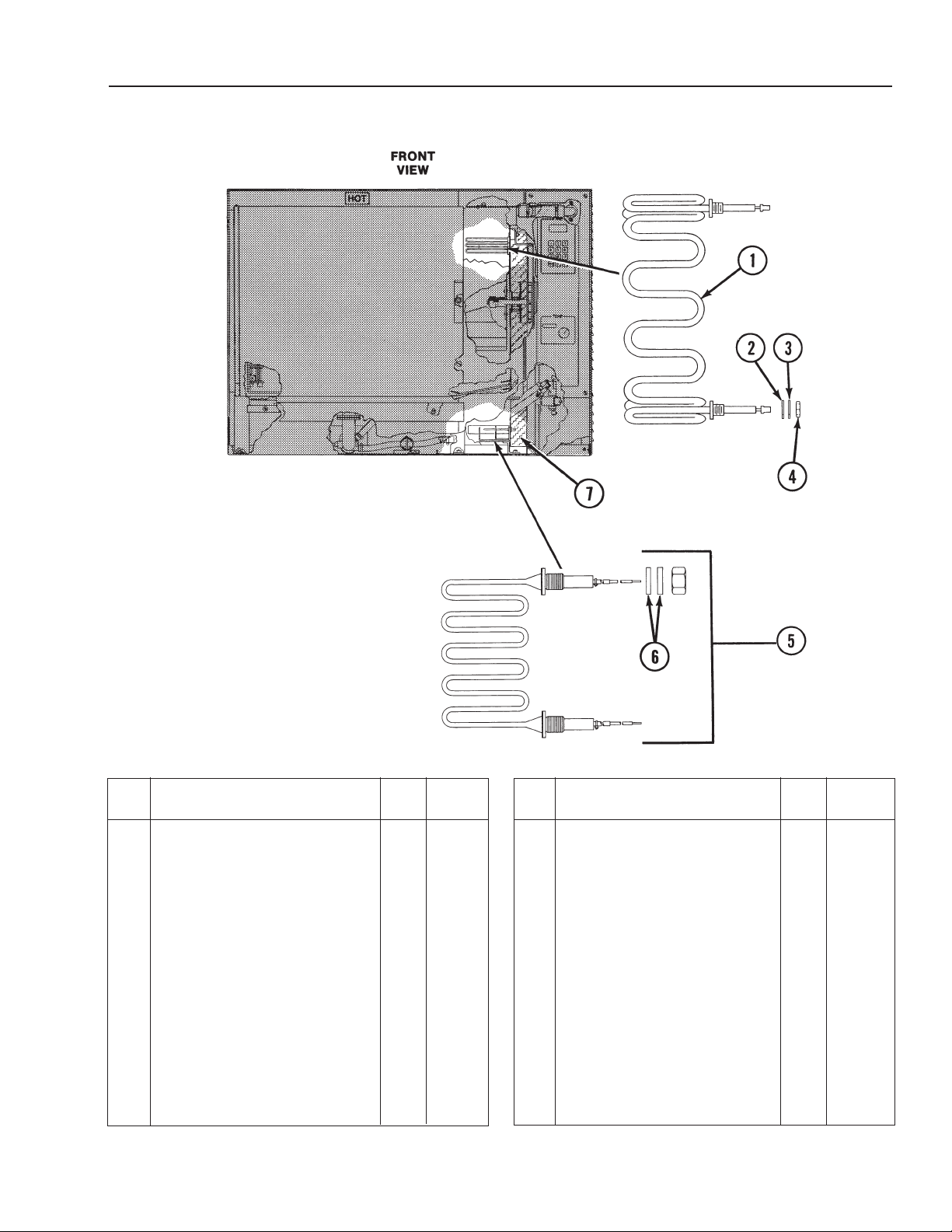
CC20-E
Parts List
Part
Item
Prior to Serial No. C10129MC
1 Air Heating Element - 208V . . 3 080608
Prior to Serial No. C10181 MC
1 Air Heating Element - 240V . . 3 081631
2 • Fiber Washer . . . . . . . . . . . . 6 *
3 • Washer . . . . . . . . . . . . . . . . 6 *
4 • Nut . . . . . . . . . . . . . . . . . . . 6 *
Starting with Serial No.
C10129MC
1 Air Heating Element - 208V . . 6 081692
Starting with Serial No.
C10181 MC
1 Air Heating Element - 240V . . 6 081691
1 Air Heating Element - 480V . . 6 081693
2 • Fiber Washer . . . . . . . . . . . . 12 *
3 • Washer . . . . . . . . . . . . . . . . . 12 114816
* Supplied with element.
(Revised 1/02)
Description Qty.
Figure 3. Heating Elements, Cavity and Insulation
No.
Item
4 • Nut . . . . . . . . . . . . . . . . . . . 12 114815
5 Heating Element -
5 Water Heating Element -
5 Water Heating Element -
6 Fiber Washer . . . . . . . . . . . . . 1
102903
7 Insulation . . . . . . . . . . . . . . . . 1 086447
Description Qty.
208V (Includes 2-Fiber
Washers, 2-Washers,
2-Nuts, and 1-Element) . . . . 3 107076
240V (Includes 2-Fiber
Washers, 2-Washers,
2-Nuts,
480V (Includes 2-Fiber
Washers, 2-Washers,
2-Nuts,
and 1-Element) . . . . 3 107077
and 1-Element) . . . . 3 107078
Part
No.
3-453-453-453-453-453-45
Page 78

CC20-E
12d
12b
12c
12a
Parts List
Item
1 Left Side Rack . . . . . . . . . . . . 1
080680
2 Middle Rack . . . . . . . . . . . . . . 5 080644
3 Shroud With Right Side Rack 1 080663
4 Door Pin Locking Nut . . . . . . . 1 003823
5 Door Latch Pin . . . . . . . . . . . 1 078914
6 Boiler Assembly Cover . . . . . . 1 081608
7 Right Side Door Switch . . . . . 1 081620
8 Left Side Door Switch . . . . . . 1 081621
9 Drip Tray . . . . . . . . . . . . . . . . 1 080772
10 Door Assembly . . . . . . . . . . . 1 See
3-463-463-463-463-463-46
Description Qty.
Figure 4. Door, Racks, and Tray
Part
No.
Part
Item
11 Door Switch Bracket . . . . . . . 1 111162
12a Left Side Insulation Strips . . . 1 080732
12b Right Side Insulation Strips . . 1 080733
12c Bottom Insulation Strips . . . . . 1 080731
12d Top Insulation Strips . . . . . . . . 1 080730
Description Qty.
(Revised 1/02)
No.
Page 79

(Revised 1/02)
14
15
Item Description Qty.
1 Fuse, 0.2 Amp., Slow Blow . . 2 073271
3 Relay Board Retro Kit
3 Relay Board . . . . . . . . . . . . . 1 120719
5 • Fuse, 3 Amp . . . . . . . . . . . . 1 077853
6 • Fuse, 4 Amp . . . . . . . . . . . . 1 077837
7 • Fuse, 20 Amp . . . . . . . . . . . 3 071489
8 • Transformer, 100VA . . . . . . 1 077838
9 • Transformer, 50V
10 • Bridge Rectifier . . . . . . . . . . 1 071487
11* Control Panel
** Cook Only . . . . . . . . . . . . . . . 1 112960
** Cook and Hold . . . . . . . . . . . 1 112961
** EPROM . . . . . . . . . . . . . . . . . 1 112955
** Top, Cook Only . . . . . . . . . . . 1 112960
** Bottom, Cook Only . . . . . . . . 1 112960
** Top, Cook and Hold . . . . . . . 1 112961
** Bottom, Cook and Hold . . . . . 1 112961
12 Control Panel Knob . . . . . . . . 1 073430
13 Fuse Block . . . . . . . . . . . . . . . 1 077840
14 Voltage Plug . . . . . . . . . . . . . . 1 106826
15 Flex Cable . . . . . . . . . . . . . . . 1 114423
* When replacing these parts be sure to install a surge
suppressor if not already installed.
** EPROM must be ordered with control panel.
Figure 5. Control Panel, and Relay Board
and Transformer Assembly
CC20-E
Parts List
Part
No.
Prior to Serial No. C7439MS
Cook . . . . . . . . . . . . . . . . . . . . 1 112980
Cook and Hold . . . . . . . . . . . . 1 112983
Starting at Serial No. C7439MS
(480V Units Only) . . . . . . . 1 099294
Prior to Serial No. C7439MS
Single Oven
Cook Only . . . . . . . . . . . . . . . 1 112960
Cook and Hold . . . . . . . . . . . 1 112961
Double-Stacked
Top, Cook Only . . . . . . . . . . . 1 112960
Bottom,
Top, Cook and Hold . . . . . . . 1 112961
Bottom, Cook and Hold . . . . . 1 112961
Starting at Serial No. C7439MS
Single Oven
Double-Stacked
Cook Only . . . . . . . . 1 112960
3-473-473-473-473-473-47
Page 80

CC20-E
Parts List
Item
Relay and Terminal Block
Assembly, 208/240V . . . . .
1 Mercury Contactor, 2PST,
35 Amp . . . . . . . . . . . . . . . . 4 077834
2 Terminal Block, 2-Pole . . . . . . 1 003887
3 Mercury Contactor, 3PST,
35 Amp . . . . . . . . . . . . . . . . 1 077848
4 Mercury Contactor,1 PST,
35 Amp . . . . . . . . . . . . . . . . 1 077849
5 Terminal Block, 3-Pole . . . . . . 1 070185
- Relay and Terminal Block
Assembly
1 Mercury Contactor, 2PST,
35 Amp . . . . . . . . . . . . . . . . 4 077834
* Not Shown.
3-483-483-483-483-483-48
Description Qty.
, 480V . . . . . . . .
Figure 6. Relay and Terminal Block Assembly and Harness
Part
No.
Part
Item
2 Not Applicable
3 Mercury Contactor, 3PST,
35 Amp . . . . . . . . . . . . . . . . 1 077848
4 Not Applicable
5 Terminal Block, 3-Pole . . . . . . 1 070185
6 Terminal Block, 3-Pole . . . . . . 2 003888
7 Surge Suppressor, 2081240V 1 098703
7 Surge Suppressor, 480V . . . . 1 098707
* Power Harness 2081240V . . . 1 077845
* Power Harness 480V . . . . . . 1 077846
* Heater to Contactor Harness,
2081240V . . . . . . . . . . . . . 1 086443
* Heater to Contactor Harness,
480V . . . . . . . . . . . . . . . . . 1 086445
8 Water Probe Harness . . . . . . 1 076494
Description Qty.
(Revised 1/02)
No.
Page 81

CC20-E
Parts List
Part
Item Description Qty.
1 Valve Housing Assembly . . . . 1 081601
2 Top Valve Assembly . . . . . . . . 1 081662
3 Vent Hose . . . . . . . . . . . . . . . 1 080689
4 Hose Clamp . . . . . . . . . . . . . 2 010873
5 Drain Seal . . . . . . . . . . . . . . . 1 080634
6 Drain Pipe Assembly . . . . . . . 1 080666
7 Drain Hose . . . . . . . . . . . . . . 1 080688
8 Hose Clamp . . . . . . . . . . . . . 2 013616
9 Drain Elbow Assembly . . . . . 1 080781
10 Spray Nozzle . . . . . . . . . . . . . 1 122839
11 Valve and Bracket Assembly 1 081671
12 • Hose Clamp . . . . . . . . . . . . 2 071271
13 • Silicone Tube . . . . . . . . . . . . 1 080631
14 • Drain Valve . . . . . . . . . . . . . 1 071234
15 • Valve Mounting Tray . . . . . 1 081612
16 • Nut, 10-32 . . . . . . . . . . . . . . 2 071256
17 Water Inlet Assembly . . . . . . 1 072151
18 Gasket . . . . . . . . . . . . . . . . . . 1 072183
19 Condensate Tube, 28-1 /2” Lg . . 1 081626
20 Water Fill Tube ,17” Lg . . . . . 1 081627
21 Hose Clamp . . . . . . . . . . . . . 4 071271
22 Solenoid Valve (2-Way) . . . . . 1 071235
23 Rear Insulation Panel . . . . . . 1 080696
24 Probe & Drain Valve Harness 1 076495
25 Flow Restrictor . . . . . . . . . . . . 1 112720
No.
(Revised 1/02)
Figure 7. Water Inlet and Drain
3-493-493-493-493-493-49
Page 82

CC20-E
Parts List
Part
Item
Door Assembly . . . . . . . . . . . 1 080645
1 Handle . . . . . . . . . . . . . . . . . . 1 129723
2 Truss Head Screw S.S. . . . . . 10 005764
3 Door Front Panel . . . . . . . . . . 1 080646
4 Insulator Board . . . . . . . . . . . . 1 080658
5 Hinge . . . . . . . . . . . . . . . . . . . 1 080642A
6 Door Spacer . . . . . . . . . . . . . 8 080654
7 Gasket . . . . . . . . . . . . . . . . . . 1 080640
8 Inner Panel . . . . . . . . . . . . . . . 1 080660
9 Hex Head Cap Screw S.S. . . 2 005608
10 Latch Assembly . . . . . . . . . . . 1 080655
11 • Retaining Ring . . . . . . . . . . . 2 073278
12 • Spring Support Pin . . . . . . . . 1 073280
13 • Door Spring . . . . . . . . . . . . . 1 078911
14 Block and Magnet Assembly 1 069762
15 Door Cam . . . . . . . . . . . . . . . 1 074252
3-503-503-503-503-503-50
Description Qty.
No.
Figure 8. Oven Door
Part
Item Description Qty.
* Loctite 242 . . . . . . . . . . . . . . 1 073282
* RTV Sealant 159 . . . . . . . . . . 1 078939
* Not Shown.
(Revised 1/02)
No.
Page 83

C/2-E
Specifications
Oven Electrical Specifications
AC Input
Voltage
280V, 3-Phase
240V, 3-Phase
480V, 3-Phase
30 to 60 PSIG. A pressure regulator is required for water pressure above
60 PSIG.
With Drain Box:
1. Drain hose to a building drain can be connected directly.
2. The drain box has an air vent that eliminates the need for an air gap.
3. Do not block the air vent in any way.
4. Do not attach anything to the vent tube or reduce the size of the
vent tube.
Current Rating
Per Line
65.4A
56.7A
28.3A
Power
21KW
21KW
21KW
Water Line Pressure
Drain Connection
(Revised 1/02)
3A-1
Page 84

C/2-E
Sequence of Events
208 or 240 Volts
Oven/Meat Probe/Hold Mode
1. Mercury relay R1 energized.
2. Relay K6, K7 and K8 energizes. Fan motor turns on.
3. Relays K11, K12, R11 and R12 energize. Air heater elements turn on.
4. When the Meat Probe reaches set point temperature for at least 30 seconds
or more, relays K11, K12, R11 and R12 de-energize. Air elements turn off.
5. Relay K6, K7 and K8 energize and de-energize, cycling the fan motor on for
10 seconds and off for 30 seconds.
6. When the oven cavity cools down to the hold set point temperature, relays
K1
1, K12, R11 and R12 energize and de-energize to maintain the cavity
temperature.
Relay Operation Summary
1. R1 energized.
2. K6, K7 and K8 energized.
3. K11, K12, R11 and R12 energized.
4. K11, K12, R11 and R12 de-energized.
5. K6, K7 and K8 energize and de-energize.
6. K11, K12, R11 and R12 energize and de-energize.
Combo/Meat Probe/Hold Mode
1. Mercury relay R1 energized.
Relays K13 and K15 energized. Boiler drain valve closes and boiler fill valve
2.
opens.
3. Relays K11, K12, R11 and R12 energize. Air elements turn on to preheat the
.
F
cavity to 200
4. Relay K6, K7 and K8 energize. Fan motor turns on.
5. When water reaches low water probe, relays K2, K3, K4, R2, R3 and R4
energize. Relay K11, K12, R11 and R12 de-energize. Water heater elements
turn on and air heater elements turn of
6. When water reaches high water probe relay K13 de-energizes and the water
fill valve closes.
°
f.
7. When boiler water temperature probe reaches READY
and R4 de-energize. Relay K2 and R2 remain energized and K5 energizes.
Boiler goes into low heat.
8. Relay K14 energizes. Condensate water spray valve opens.
3A-2
, relays K3, K4, R3
(Revised 1/02)
Page 85

C/2-E
Sequence Of Events
9. Relays K11, K12, R11 and R12 energize. Air heater elements turn on.
10. When the Meat Probe reaches set point temperature for at least 30 seconds
or more, relays K11, K12, R11 and R12 de-energize. Air elements turn off.
11. Relays K6, K7 and K8 energize and de-energize, cycling the fan motor turns
on for 10 seconds and off for 30 seconds.
12. When the oven cavity cools down to the hold set point temperature, relays
K11, K12, R11 and R12 energize and de-energize to maintain the cavity
temperature.
Relay Operation Summary
1. R1 energized.
2. K13 and K15 energized.
3. K11, K12, R11 and R12 energized.
4. K6, K7 and K8 energized.
5. K2, K3, K4, R2, R3 and R4 energized. K11, K12, R11 and R12 deenergized.
6. K13 de-energized.
7. K3 and K4 de-energized. K2 and K5 energized.
8. Relay K14 energized.
9. K11, K12, R11 and R12 energized.
10. K11, K12, R11 and R12 de-energized.
11. K6, K7 and K8 energize and de-energize.
12. K11, K12, R11 and R12 energize and de-energize.
(Revised 1/02)
3A-3
Page 86

C/2-E
Sequence Of Events
480 Volts
Oven/Meat Probe/Hold Mode
1. Relay K6 and mercury relay R1 energized. Fan motor turns on.
2. Relays K11, K12, R11 and R12 energize. Air heater elements turn on.
3. When the Meat Probe reaches set point temperature for at least 30 seconds
or more, relays K11, K12, R11 and R12 de-energize. Air elements turn off.
4. Relays K6 and R1 energize and de-energize, cycling the fan motor on for 10
seconds and off for 30 seconds.
5. When the oven cavity cools down to the hold set point temperature, relays
K11, K12, R11 and R12 energize and de-energize to maintain the cavity
temperature.
Relay Operation Summary
1. K6 and R1 energized.
2. K11, K12, R11 and R12 energized.
3. K11, K12, R11 and R12 de-energized.
4. K6 and R1 energize and de-energize.
5. K11, K12, R11 and R12 energize and de-energize.
Combo/Meat Probe/Hold Mode
1. Relays K13 and K15 energized. Boiler drain valve closes and boiler fill valve
opens.
2. Relay K6 and mercury relay R1 energized. Fan motor turns on.
3. Relays K11, K12, R11 and R12 energize. Air elements turn on to preheat the
cavity to 200°F.
4. When water reaches low water probe, relays K2, K3, R2 and R3 energize.
Relay K11, K12, R11 and R12 de-energize. Water heater elements turn on
and air heater elements turn off.
When water reaches high water probe relay K13 de-energizes and the water
5.
fill valve closes.
When boiler water temperature probe reaches READY, relays K3 and R3 de-
6.
energize. Relays K2 and R2 remain energized. Boiler goes into low heat.
7. Relay K14 energizes. Condensate water spray valve opens.
Relays K11, K12, R11 and R12 energize. Air heater elements turn on.
8.
9. When the Meat Probe reaches set point temperature for at least 30 seconds
or more, relays K11, K12, R11 and R12 de-energize. Air elements turn off.
3A-4
(Revised 1/02)
Page 87

C/2-E
Sequence Of Events
10. Relay K6 and R1 energize and de-energize, cycling the fan motor on for 10
seconds and off for 30 seconds.
11. When the oven cavity cools down to the hold set point temperature, relays
K11, K12, R11 and R12 energize and de-energize to maintain the cavity
temperature.
Relay Operation Summary
1. K13 and K15 energized.
2. K6 and R1 energized.
3. K11, K12, R11 and R12 energized.
4. K2, K3, R2 and R3 energized. K11, K12, R11 and R12 de-energized.
5. K13 de-energized.
6. K3 and R3 de-energized. K2 and R2 energized.
7. Relay K14 energized.
8. K11, K12, R11 and R12 energized.
9. K11, K12, R11 and R12 de-energized.
10. K6 and R1 energize and de-energize.
11. K11, K12, R11 and R12 energize and de-energize.
(Revised 1/02)
3A-5
Page 88

C/2-E
Operation
The model C/2-E is a combination steamer-oven with a stainless steel cooking
chamber, a steam generator, and electronic circuitry for controlling unit operation.
The C/2-E oven operates from a three phase power supply only.
It can function as a convection oven, a self-contained pressureless steamer, or
as a combination oven-steamer. The control panel touch pad switches control
mode of operation. The control panel is available as cook only, cook and hold
with a meat probe, or programmable with a meat probe.
Replaceable electric air heating elements and the blower fan provide for oven
temperatures up to a maximum of 575°F; except when cooking with the meat
probe, the maximum oven temperature is 500°F.
Replaceable electric generator heating elements are used to generate steam.
The steam generator cavity is adjacent to the cooking compartment and easily
accessible.
the unit is turned off, or the cook mode is selected, the steam generator
automatically drains. When no mode is selected, the steam generator fills with
water and is heated and held at 160°F.
All of the condensate leaves the oven through the cavity drain. When
The control panel is a solid-state controller. The solid-state circuitry has a selfdiagnostic program to assist in troubleshooting, and a pre-programmed cleaning
cycle to assist the operator in daily cleaning.
The door interlock switch operates to turn off the fan and oven (air) heating
elements, and turns the steam generator heater elements to low power, when
the door is opened.
The electric circuits that are active for the three operating modes, and optional
hold and meat probe modes, are shown in the following illustrations.
3A-6
(Revised 1/02)
Page 89

7000 W
L1
L2
L3
DB1
T
B 2
T
B 1
RED
W
HITE
B
LACK
R1
R3
R2
R4
B
H1 BH2 BH3
TO K5 (14 AWG)
(
12) 12 AWG
A
3
A5
A6
A1
(6) HEATERS
2915 W EA.
(
6) 12 AWG
(
8) 12 AWG
R11 R12
AIR
W
IRES 105°C 600 V
B
1 B2 B3 B4 B5 B6
TB3
FAN
7000 W
7000 W
2
00°C
UNLESS NOTED
A1
A3
A5
A6
A4
A2
A4
A2
GND
-4
MOV
-
2
MOV
-3
MOV
M
OV
-
6
MOV
-
1
-5
MOV
MOV BOARD
WHT
RED
BLK
K1
DL1-4
208
3.2A
COM
24V
CB
75VA
TR2
WHITE
RED
K6
K7
K8
5-PIN
CONNECTOR
M1
M2
M3
M4
M5
M2
M4
M5
M3
M1
KEY
M1
MOTOR
1/5 HP, 3 PHASE
208-240V
TR1
24V
COM
208
240
480
100 VA
F4
4A
K2
K3
K4
K5
K11
K12
K13
K14
K15
14 AWG
TO B-3TO B-2
CONDENSATE
BOILER FILL
R12
R11
R4
R3
R2
R1
AC+
AC-
DC
VALVE
DRAIN
240
TC1 TC2
AIR BOILER
610 F 610 F
208V-240V
B
A
9
9
J4
FB1
6 4 1
8 7 6 5 4 3 2 1
RELAY BOARD
14 VAC
28 VAC
1.25 AMP
1.25 AMP
D
C
RELAY BOARD
POWER TO
14 VAC
BLOCK DB1
DISTRIBUTION
L1 L2 L3
14 AWG
RED
WHT
BLK
F1
20AF220A
F3
20A
FB2 FB3
K = RELAY ON RELAY BOARD
R = POWER RELAY
ALL WIRES ARE 18 AWG 105°C 600V UNLESS MARKED
3A
F
7
C/2-E
Electrical Diagrams
Steam Mode Circuit for 208/240 Volt Units
(Revised 1/02)
3A-7
Page 90

C/2-E
L1
L3
L2
DB1
B
LK
WHT
R
ED
R2
B
H1
7000 W
B
1
T
B1
B
5
WIRES 14 AWG 600V 105°C UNLESS NOTED
R3
B2B
3
B
H2
B
4
7000 W
BOILER
R
11
T
B2
B
H3
B
6
A4
A2
A6
7000 W
A1
A3
A5
FAN
R
12
A6
A2
A4
A
1
A5
A
3
AIR
GND
-4
M
OV
-2
MOV
-3
M
OV
MOV
-6
MOV
-1
-5
MOV
MOV BOARD
RED
WHT
BLK
3.2A
CB
K1
COM
WHITE
24V
75VA
TR2
RED
480
R2
R3
AC-
AC+
BOILER FILL
R12
R11
CONDENSATE
VALVE
DRAIN
DC
K6
K2 K15
K3
K12
K11
K14
K13
R1
COM
208
240
480
24V
TR1
100 VA
4A
F4
3A
F7
J4
3
208V-240V
B
7998
64
564
A
1
12
14 VAC
14 VAC
1.25 AMP
1.25 AMP
POWER TO
RELAY BOARD
2
8 VAC
DC
DL1-4
AIR
TC1
610 F
BOILER
TC2
610 F
KEY
480V
MOTOR
1/5 HP
3 PHASE
MOTOR IS
THERMALLY
PROTECTED
CONNECTOR
6-PIN
M1
M2
M3
M4
M5
NCM2NC
M5
M3
M4
M1
220V
480V
TR3
50 VA
RED
F1
20AF220A
WHT
F3
20A
BLK
14 AWG
L1
TO DISTRIBUTION
L2 L3
BLOCK
R1
K = RELAY ON RELAY BOARD
R = POWER RELAY
WIRES ARE 18 AWG 600V 105°C UNLESS MARKED
M1
FB1 FB2 FB3
Electrical Diagrams
Steam Mode Circuit for 480 Volt Units
3A-8
(Revised 1/02)
Page 91

C/2-E
K1
DL1-4
208
3.2A
COM
24V
CB
75VA
TR2
WHITE
RED
K6
K7
K8
5-PIN
CONNECTOR
M1
M2
M3
M4
M5
M2
M4
M5
M3
M1
KEY
M1
MOTOR
1/5 HP, 3 PHASE
208-240V
TR1
24V
COM
208
240
480
100 VA
F4
4A
K2
K3
K4
K5
K11
K12
K13
K14
K15
14 AWG
TO B-3TO B-2
CONDENSATE
BOILER FILL
R12
R11
R4
R3
R2
R1
AC+
AC-
DC
VALVE
DRAIN
240
TC1 TC2
AIR BOILER
610 F 610 F
208V-240V
B
A
9
9
J4
FB1
64 1
87654321
RELAY BOARD
14 VAC
28 VAC
1.25 AMP
1.25 AMP
DC
RELAY BOARD
POWER TO
14 VAC
BLOCK DB1
DISTRIBUTION
L
1 L2 L3
14 AWG
RED
WHT
BLK
F1
20AF220A
F3
20A
FB2 FB3
K = RELAY ON RELAY BOARD
R = POWER RELAY
ALL WIRES ARE 18 AWG 105°C 600V UNLESS MARKED
3A
F7
7000 W
L1
L2
L3
DB1
T
B 2
T
B 1
RED
WHITE
BLACK
R1
R3
R2
R
4
BH1 BH2 BH3
TO K5 (14 AWG)
(12) 12 AWG
A3
A5
A6
A1
(6) HEATERS
2915 W EA.
(6) 12 AWG
(
8) 12 AWG
R11 R12
AIR
BOILER
WIRES 105°C 600 V
B1 B2 B3 B4 B5 B6
T
B3
FAN
7000 W
7000 W
200°C
UNLESS NOTED
A1
A3
A5
A
6
A
4
A2
A4
A2
G
ND
-4
MOV
-2
MOV
-3
MOV
M
OV
-
6
MOV
-1
-5
MOV
MOV BOARD
WHT
RED
BLK
Electrical Diagrams
Combo Mode Circuit for 208/240 Volt Units
(Revised 1/02)
3A-9
Page 92
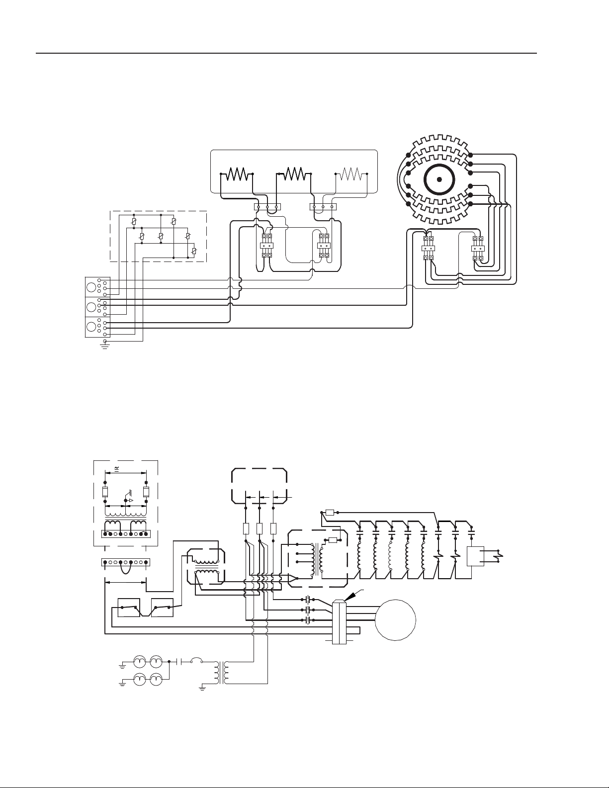
C/2-E
L1
L3
L2
DB1
BLK
WHT
R
ED
R2
B
H1
7000 W
B1
T
B1
B5
WIRES 14 AWG 600V 105°C UNLESS NOTED
R3
B2 B3
B
H2
B4
7000 W
BOILER
R
11
T
B2
BH3
B6
A4
A2
A6
7000 W
A1
A3
A
5
FAN
R
12
A6
A2
A
4
A1
A5
A3
AIR
GND
-4
MOV
-2
MOV
-3
MOV
MOV
-6
MOV
-1
-5
MOV
MOV BOARD
RED
WHT
BLK
3.2A
CB
K1
COM
WHITE
24V
75VA
TR2
RED
480
R2
R3
AC-
AC+
BOILER FILL
R12
R11
CONDENSATE
VALVE
DRAIN
DC
K6
K2 K15
K3
K12
K11
K14
K13
R1
COM
208
240
480
24V
TR1
100 VA
4A
F4
3A
F7
J4
3
208V-240V
B
7998
64
564
A
1
12
14 VAC
14 VAC
1.25 AMP
1.25 AMP
POWER TO
RELAY BOARD
28 VAC
D
C
DL1-4
AIR
TC1
610 F
BOILER
TC2
610 F
KEY
480V
MOTOR
1/5 HP
3 PHASE
MOTOR IS
THERMALLY
PROTECTED
CONNECTOR
6-PIN
M1
M2
M3
M4
M5
NC
M2
NC
M5
M3
M4
M1
220V
480V
TR3
50 VA
RED
F1
20AF220A
WHT
F3
20A
BLK
14 AWG
L1
TO DISTRIBUTION
L2 L3
BLOCK
R1
K = RELAY ON RELAY BOARD
R = POWER RELAY
WIRES ARE 18 AWG 600V 105°C UNLESS MARKED
M1
FB1 FB2 FB3
Electrical Diagrams
Combo Mode Circuit for 480 Volt Units
3A-10
(Revised 1/02)
Page 93

K1
DL1-4
208
3.2A
COM
24V
CB
75VA
TR2
WHITE
RED
K6
K7
K8
5-PIN
CONNECTOR
M1
M2
M3
M4
M5
M2
M4
M5
M3
M1
KEY
M1
MOTOR
1/5 HP, 3 PHASE
208-240V
TR1
24V
COM
208
240
480
100 VA
F4
4A
K2
K3
K4
K5
K11
K12
K13
K14
K15
14 AWG
TO B-3TO B-2
CONDENSATE
BOILER FILL
R12
R11
R4
R3
R2
R1
AC+
AC-
DC
VALVE
DRAIN
240
TC1 TC2
AIR BOILER
610 F 610 F
208V-240V
B
A
9
9
J4
FB1
64 1
87654321
RELAY BOARD
14 VAC
28 VAC
1.25 AMP
1.25 AMP
DC
RELAY BOARD
POWER TO
14 VAC
BLOCK DB1
DISTRIBUTION
L1 L2 L3
14 AWG
RED
WHT
BLK
F1
20AF220A
F3
20A
FB2 FB3
K = RELAY ON RELAY BOARD
R = POWER RELAY
ALL WIRES ARE 18 AWG 105°C 600V UNLESS MARKED
3A
F7
7000 W
L1
L2
L3
DB1
TB 2
TB 1
RED
WHITE
B
LACK
R
1
R
3
R2
R4
BH1 BH2 BH3
T
O K5 (14 AWG)
(
12) 12 AWG
A3
A5
A6
A1
(
6) HEATERS
2915 W EA.
(6) 12 AWG
(
8) 12 AWG
R
11 R12
AIR
BOILER
W
IRES 105°C 600 V
B1 B2 B3 B4 B5 B6
TB3
FAN
7000 W
7000 W
2
00°C
UNLESS NOTED
A1
A3
A
5
A6
A4
A2
A
4
A2
GND
-4
MOV
-2
MOV
-3
MOV
MOV
-6
MOV
-1
-5
MOV
MOV BOARD
WHT
RED
BLK
C/2-E
Electrical Diagrams
Oven Mode Circuit for 208/240 Volt Units
(Revised 1/02)
3A-11
Page 94
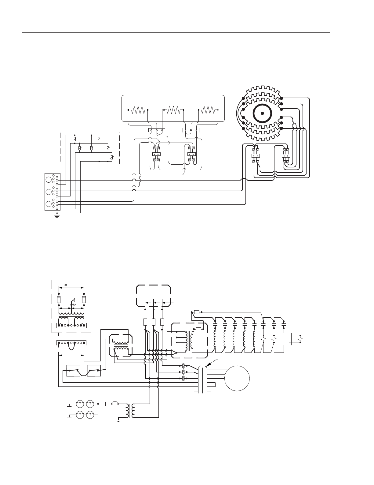
C/2-E
3.2A
CB
K1
COM
WHITE
24V
75VA
TR2
RED
480
R2
R3
AC-
AC+
BOILER FILL
R12
R11
CONDENSATE
VALVE
DRAIN
DC
K6
K2 K15
K3
K12
K11
K14
K13
R1
COM
208
240
480
24V
TR1
100 VA
4A
F4
3A
F7
J4
3
208V-240V
B
7998
64
564
A
1
12
14 VAC
14 VAC
1.25 AMP
1.25 AMP
POWER TO
RELAY BOARD
2
8 VAC
DC
DL1-4
AIR
TC1
610 F
BOILER
TC2
610 F
KEY
480V
MOTOR
1/5 HP
3 PHASE
MOTOR IS
THERMALLY
PROTECTED
CONNECTOR
6-PIN
M1
M2
M3
M4
M5
NC
M2
NC
M5
M3
M4
M1
220V
480V
TR3
50 VA
RED
F1
20AF220A
WHT
F3
20A
BLK
14 AWG
L1
TO DISTRIBUTION
L2 L3
BLOCK
R1
K = RELAY ON RELAY BOARD
R = POWER RELAY
WIRES ARE 18 AWG 600V 105°C UNLESS MARKED
M1
FB1 FB2 FB3
L1
L3
L2
L1
DB1
B
LK
W
HT
R
ED
R2
BH1
7000 W
B1
T
B1
B5
WIRES 14 AWG 600V 105°C UNLESS NOTED
R3
B2 B3
BH2
B4
7000 W
BOILER
R11
T
B2
B
H3
B6
A
4
A2
A6
7000 W
A1
A3
A5
FAN
R
12
A6
A
2
A
4
A1
A5
A3
AIR
GND
-4
MOV
-2
MOV
-3
MOV
MOV
-6
MOV
-1
-
5
MOV
MOV BOARD
RED
WHT
BLK
Electrical Diagrams
Oven Mode Circuit for 480 Volt Units
3A-12
(Revised 1/02)
Page 95

K1
DL1-4
208
3.2A
COM
24V
CB
75VA
TR2
WHITE
RED
K6
K7
K8
5-PIN
CONNECTOR
M1
M2
M3
M4
M5
M2
M4
M5
M3
M1
KEY
M1
MOTOR
1/5 HP, 3 PHASE
208-240V
TR1
24V
COM
208
240
480
100 VA
F4
4A
K2
K3
K4
K5
K11
K12
K13
K14
K15
14 AWG
TO B-3TO B-2
CONDENSATE
BOILER FILL
R12
R11
R4
R3
R2
R1
AC+
AC-
DC
VALVE
DRAIN
240
TC1 TC2
AIR BOILER
610 F 610 F
208V-240V
B
A
9
9
J4
FB1
64 1
87654321
RELAY BOARD
14 VAC
28 VAC
1.25 AMP
1.25 AMP
DC
RELAY BOARD
POWER TO
14 VAC
BLOCK DB1
DISTRIBUTION
L1 L2 L3
14 AWG
RED
WHT
BLK
F1
20AF220A
F3
20A
FB2 FB3
K = RELAY ON RELAY BOARD
R = POWER RELAY
ALL WIRES ARE 18 AWG 105°C 600V UNLESS MARKED
3A
F7
7000 W
L1
L2
L3
DB1
TB 2
TB 1
RED
WHITE
B
LACK
R
1
R
3
R2
R4
BH1 BH2 BH3
T
O K5 (14 AWG)
(
12) 12 AWG
A3
A5
A6
A1
(
6) HEATERS
2915 W EA.
(6) 12 AWG
(
8) 12 AWG
R
11 R12
AIR
BOILER
W
IRES 105°C 600 V
B1 B2 B3 B4 B5 B6
TB3
FAN
7000 W
7000 W
2
00°C
UNLESS NOTED
A1
A3
A
5
A6
A4
A2
A
4
A2
GND
-4
MOV
-2
MOV
-3
MOV
MOV
-6
MOV
-1
-5
MOV
MOV BOARD
WHT
RED
BLK
C/2-E
Electrical Diagrams
Schematic Diagram for C/2-E 208/240 Volt Units
(Revised 1/02)
3A-13
Page 96

C/2-E
3.2A
CB
K1
COM
WHITE
24V
75VA
TR2
RED
480
R2
R3
AC-
AC+
BOILER FILL
R12
R11
CONDENSATE
VALVE
DRAIN
DC
K6
K2 K15
K3
K12
K11
K14
K13
R1
COM
208
240
480
24V
TR1
100 VA
4A
F4
3A
F7
J4
3
208V-240V
B
7998
64
564
A
1
12
14 VAC
14 VAC
1.25 AMP
1.25 AMP
POWER TO
RELAY BOARD
2
8 VAC
DC
DL1-4
AIR
TC1
610 F
BOILER
TC2
610 F
KEY
480V
MOTOR
1/5 HP
3 PHASE
MOTOR IS
THERMALLY
PROTECTED
CONNECTOR
6-PIN
M1
M2
M3
M4
M5
NC
M2
NC
M5
M3
M4
M1
220V
480V
TR3
50 VA
RED
F1
20AF220A
WHT
F3
20A
BLK
14 AWG
L1
TO DISTRIBUTION
L2 L3
BLOCK
R1
K = RELAY ON RELAY BOARD
R = POWER RELAY
WIRES ARE 18 AWG 600V 105°C UNLESS MARKED
M1
FB1 FB2 FB3
L1
L3
L2
L1
DB1
B
LK
W
HT
R
ED
R2
BH1
7000 W
B1
T
B1
B5
WIRES 14 AWG 600V 105°C UNLESS NOTED
R3
B2 B3
BH2
B4
7000 W
BOILER
R11
T
B2
B
H3
B6
A
4
A2
A6
7000 W
A1
A3
A5
FAN
R
12
A6
A
2
A
4
A1
A5
A3
AIR
GND
-4
MOV
-2
MOV
-3
MOV
MOV
-6
MOV
-1
-
5
MOV
MOV BOARD
RED
WHT
BLK
Electrical Diagrams
Schematic Diagram for C/2-E 480 Volt Units
3A-14
(Revised 1/02)
Page 97

C/2-E
Parts List
C/2-E
Sequence Of Events
Item Description Qty.
1 Left Side Rack........................... 1 080680
2 Middle Rack............................... 5 080644
3 Shroud with Right Side Rack .... 1 080663
4 Door Pin Locking Nut ................ 1 003823
5 Door Latch Pin .......................... 1 078914
6 Boiler Assembly Cover.............. 1 081608
Figure 4. Door, Racks, and Tray
(Revised 1/02)
Part
No.
Item Description Qty.
7 Right Side Door Switch ........... 1 081620
8 Left Side Door Switch................ 1 081621
9 Drip Tray.................................... 1 080772
10 Door Assembly ........................ 1 See
Fig. 9
Part
No.
3A-15
Page 98

C/2-E
6
1
11
4
10
3
3
7
2
5
Gordon
C/2-E
Sequence Of Events
Parts List
Part
Item Description Qty.
1 Control Panel (Cook Only) ...... 1 124808
1 Control Panel (Cook, Hold
and Probe) ........................... 1 124309
2 EPROM (Cook Only; Cook,
Hold and Probe)................... 1 120749
1 Control Panel
(Programmable) ................... 1 124815
2 EPROM (Programmable) ........ 1 118809
3 Fuse 0.5 Amp, Slow Blow....... 2 087947
4 Relay Board ............................ 1 112964
5 Control Panel Knob................. 1 073430
6 Voltage Plug............................ 1 106826
7 Flexible Cable with Grounded
Shield ................................... 1 114423
8 Transformer 100 VA ................ 1 077838
9 Transformer 50 VA (480 volt
units only) ............................ 1 099294
10 Bridge Rectifier........................ 1 071487
11 Meat Probe.............................. 1 111385
No.
3A-16
* EPROM must be ordered with the control panel.
Figure 5. Control Panel, Relay Board and Transformer Assembly
(Revised 1/02)
Page 99

17
15
8
7
13
12
11
9
22
7
18
35
19 21 22 24
22
20 7 23
25
262728 29 30
31 32 33
34
14
6
5
4
3
2
1
10
16
129727
C/2-E
Parts List
C/2-E
Parts List
(Revised 1/02)
Figure 8. Glass Door
3A-173A-17
Page 100

C/2-E
Parts List
Part
Item Description Qty.
1 Assembly, Door Front Panel ... 1 133847
2 Screw, #10-32 x .375 Phillips
Flat Head ............................. 8 069723
3 Handle..................................... 1 129723
4 Spacer, Cam ........................... 2 123744
5 Assembly, Cam ....................... 1 074252
6 Screw, #8-32 x 1.00 Phillips
Torx Head Locking ............... 2 123718
7 Screw, #8-32 x .375 Phillips
Torx Head Locking ............... 6 129732
8 Assembly, Door Magnet .......... 1 129726
9 Nut, #10-32 SS ....................... 1 002632
10 Mandrel, Spring....................... 1 130864
11 Spring ...................................... 1 078911
12 Spacer, Door Latch ................. 1 094146
13 Weldment, Door Latch
Bracket................................. 1 123572
14 Weldment, Door Inside
Panel.................................... 1 123528
15 Spring, Extension .................... 2 123592
16 Weldment, Retention Clip
Mounting Bracket................. 2 123540
17 Clip, Inner Door Retention ...... 2 123539
18 Assembly, Inner Door.............. 1 123548
19 Gasket, Inner Door.................. 1 123596
20 Bumper, Stem ......................... 6 123588
21 Bracket, Condensate
Deflector............................... 1 138389
22 Screw, #8-32 x .375 Phillips
Flat Undercut Head.............. 6 127178
23 Screw, 1/4-20 x .50 Phillips
Flat Head ............................. 2 123721
24 Hinge, with Mounting Hole ...... 2 123507
25 Assembly, Light Box Cover ..... 1 123570
26 Lamp ....................................... 4 112733
27 Assembly, Light Bar Insulator . 1 123597
28 Screw, #8/32 x .50 Socket
Button Head......................... 2 093255
29 Nut, #8-32 with SEMS............. 2 069784
30 Clip, Fuse 13/32 Dia. S.S. ...... 2 112735
31 Washer, #10 Shoulder............. 1 123866
32 Washer, #10 ............................ 1 014812
33 Nut, #10-32 with SEMS........... 1 071256
34 Weldment, Light Box
Bracket................................. 1 123569
35 Cord, Jumper-Door Light ........ 1 127174
No.
3A-183A-18
(Revised 1/02)
 Loading...