

Page 1
OPERATOR MANUAL
IMPORTANT INFORMATION, KEEP FOR OPERATOR
This manual provides information for:
MODEL DH/INA/2-100
STEAM JACKETED
KETTLE
· Self-Contained
· Gas Heated
· Floor Mounted
· Tilting
THIS MANUAL MUST BE RETAINED FOR FUTURE REFERENCE.
READ, UNDERSTAND AND FOLLOW THE INSTRUCTIONS AND
WARNINGS CONTAINED IN THIS MANUAL.
FOR YOUR SAFETY
Do not store or use gasoline or other flammable vapors
and liquids in the vicinity of this or any other appliance.
POST IN A PROMINENT LOCATION
Instructions to be followed in the event user smells gas.
This information shall be obtained by consulting your
local gas supplier. As a minimum, turn off the gas and
call your gas company and your authorized service agent.
Evacuate all personnel from the area.
WARNING
Improper installation, adjustment, alteration, service or
maintenance can cause property damage, injury or death.
Read the installation, operating and maintenance instructions
thoroughly before installing or servicing this equipment.
NOTIFY CARRIER OF DAMAGE AT ONCE
It is the responsibility of the consignee to inspect the container upon receipt of
same and to determine the possibility of any damage, including concealed dam-
age. Unied Brands suggests that if you are suspicious of damage to make a
notation on the delivery receipt. It will be the responsibility of the consignee to le
a claim with the carrier. We recommend that you do so at once.
Manufacture Service/Questions 888-994-7636.
Information contained in this document is known to be current and accurate at the time
of printing/creation. Unified Brands recommends referencing our product line websites,
unifiedbrands.net, for the most updated product information and specifications.
PART NUMBER 176302, REV. A (01/18)
1055 Mendell Davis Drive
Jackson, MS 39272
888-994-7636, fax 888-864-7636
unifiedbrands.net
Page 2

IMPORTANT - READ FIRST - IMPORTANT
WARNING: FAILURE TO DISCONNECT POWER BEFORE SERVICING COULD RESULT IN ELECTROCUTION AND
DEATH.
WARNING: IMPROPER INSTALLATION, ADJUSTMENT, ALTERATION, SERVICE OR MAINTENANCE CAN CAUSE
PROPERTY DAMAGE, INJURY OR DEATH. READ THE INSTALLATION, OPERATING AND MAINTENANCE
INSTRUCTIONS THOROUGHLY BEFORE INSTALLING OR SERVICING THIS EQUIPMENT.
WARNING: DO NOT PLACE HANDS, TOOLS OR HOSES IN KETTLE WHILE AGITATOR IS MOVING. AGITATOR CAN
BE JOGGED WHILE KETTLE IS TILTED.
WARNING: THE UNIT MUST BE INSTALLED BY PERSONNEL QUALIFIED TO WORK WITH ELECTRICITY AND
PLUMBING. UNIT MUST BE INSTALLED IN ACCORDANCE WITH ALL APPLICABLE CODES.
WARNING: DO NOT ATTACH THE UNIT TO A TYPE “B” VENT. IT COULD CAUSE FIRE OR PROPERTY DAMAGE.
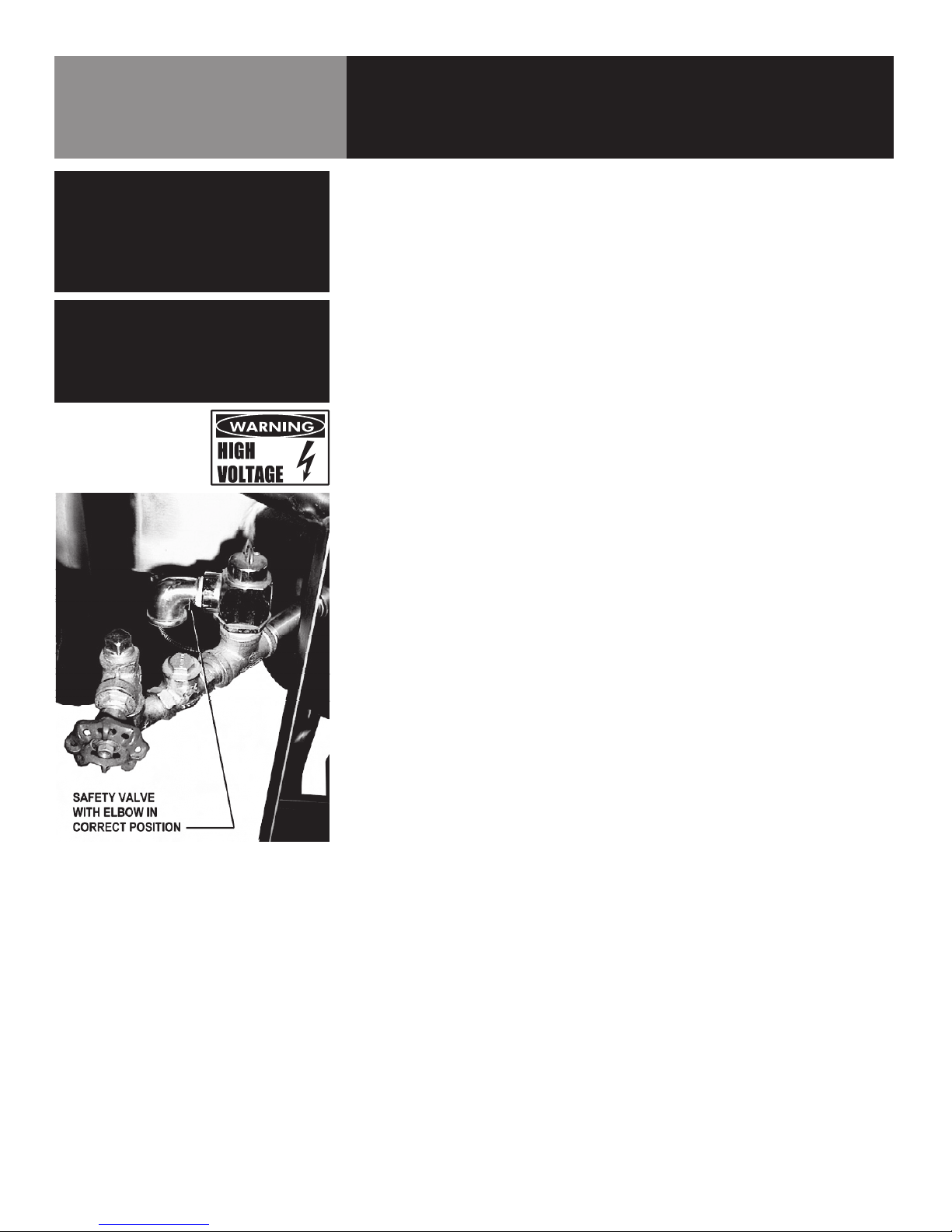
WARNING: DO NOT CONNECT ANY PIPING TO THE SAFETY VALVE. IT MUST BE FREE TO VENT STEAM AS
NEEDED. TO AVOID BURNS FROM THE VENTED STEAM THE VALVE DISCHARGE SHOULD POINT
DOWNWARD.
DANGER: ELECTRICALLY GROUND THE UNIT AT THE TERMINAL PROVIDED. FAILURE TO GROUND THE UNIT
COULD RESULT IN ELECTROCUTION AND DEATH.
CAUTION: BE SURE ALL OPERATORS READ, UNDERSTAND AND FOLLOW THE OPERATING INSTRUCTIONS,
CAUTIONS AND SAFETY INSTRUCTIONS CONTAINED IN THIS MANUAL.
CAUTION: DO NOT OVERFILL THE KETTLE WHEN COOKING, HOLDING OR CLEANING. KEEP LIQUIDS A
MINIMUM OF 2-3” (5-8 CM) BELOW THE KETTLE BODY RIM TO ALLOW CLEARANCE FOR STIRRING,
BOILING AND SAFE TRANSFER OF PRODUCT.
CAUTION: KEEP FLOORS IN FRONT OF KETTLE WORK AREA CLEAN AND DRY. IF SPILLS OCCUR, CLEAN
IMMEDIATELY TO AVOID SLIPS OR FALLS.
WARNING: KEEP WATER AND SOLUTIONS OUT OF CONTROLS AND BURNERS. NEVER SPRAY OR HOSE DOWN
THE CONTROL CONSOLE, ELECTRICAL CONNECTIONS, ETC.
CAUTION: MOST CLEANERS ARE HARMFUL TO THE SKIN, EYES, MUCOUS MEMBRANES AND CLOTHING. TAKE
PRECAUTIONS: WEAR RUBBER GLOVES, GOGGLES OR FACE SHIELD AND PROTECTIVE CLOTHING.
CAREFULLY READ WARNINGS AND FOLLOW DIRECTIONS ON CLEANER LABELS .
NOTICE: NEVER LEAVE A SANITIZER IN CONTACT WITH STAINLESS STEEL SURFACES LONGER THAN 10
MINUTES. LONGER CONTACT CAN CAUSE CORROSION.
WARNING: FAILURE TO PERIODICALLY CHECK SAFETY VALVE OPERATION COULD RESULT IN PERSONAL
INJURY AND/OR DAMAGE TO EQUIPMENT.
WARNING: WHEN TESTING, AVOID EXPOSURE TO THE STEAM BLOWING OUT OF THE SAFETY VALVE. DIRECT
CONTACT COULD RESULT IN SEVERE BURNS.
WARNING: TO AVOID INJURY, READ AND FOLLOW ALL PRECAUTIONS STATED ON THE LABEL OF THE WATER
TREATMENT COMPOUND.
WARNING: BEFORE REPLACING ANY PARTS, DISCONNECT THE UNIT FROM THE ELECTRIC POWER SUPPLY
AND CLOSE THE MAIN GAS VALVE. ALLOW FIVE MINUTES FOR GAS TO VENT.
CAUTION: USE OF ANY REPLACEMENT PARTS OTHER THAN THOSE SUPPLIED BY GROEN OR AUTHORIZED
DISTRIBUTORS CAN CAUSE INJURY TO THE OPERATOR AND DAMAGE TO THE EQUIPMENT AND
WILL VOID ALL WARRANTIES.
2 OM-DH/INA/2-100
Page 3

IMPORTANT - READ FIRST - IMPORTANT
WARNING: KEEP AREA AROUND KETTLE FREE AND CLEAR OF ALL COMBUSTIBLE MATERIALS. FAILURE TO DO
SO COULD RESULT IN FIRE OR PROPERTY DAMAGE.
CAUTION: HEATING AN EMPTY KETTLE MAY CAUSE THE RELEASE OF STEAM FROM THE SAFETY VALVE.
IMPORTANT: SERVICE PERFORMED BY OTHER THAN FACTORY AUTHORIZED PERSONNEL WILL VOID ALL
WARRANTIES.
OM-DH/INA/2-100 3
Page 4

Table of Contents
Important Operator Warnings ....................................................page 2-3
References.................................................................................... page 4
Equipment Description.................................................................. page 5
Inspection and Unpacking ......................................................... page 6-7
Installation .................................................................................. page 8-9
Initial Start-Up............................................................................... page 10
Operation ................................................................................ page 11-16
Cleaning........................................................................................ page 17
Maintenance............................................................................ page 18-20
Sequence of Operation ............................................................... page 21
Troubleshooting...................................................................... page 22-23
Part Lists ............................................................................ page 24-36
Wiring Diagram ............................................................................ page 37
Service Log ................................................................................. page 39
References
KLENZADE SALES CENTER
ECOLAB. Inc.
370 Wabasha
St. Paul, Minnesota 55102
800/352-5326 or 612/293-2233
NATIONAL FIRE PROTECTION ASSOCIATION
60 Battery March Park
Quincy, Massachusetts 02269
NFPA/54 Installation of Gas Appliances &
Gas Piping
NFPA/70 The National Electrical Code
NSF INTERNATIONAL
789 N. Dixboro Rd.
P.O. Box 130140
Ann Arbor, Michigan 48113
UNDERWRITERS LABORATORIES, INC.
333 Pngsten Road
Northbrook, Illinois 60062
4 OM-DH/INA/2-100
ZEP MANUFACTURING CO.
1310-T Seaboard Industrial Blvd.
Atlanta, Georgia 30318
Page 5
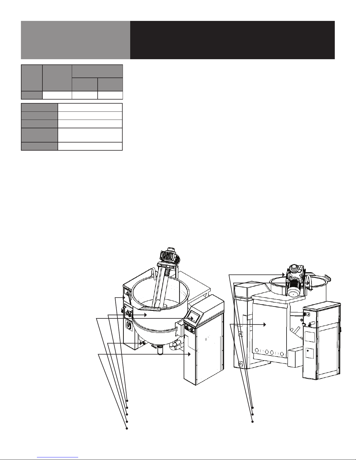
Equipment Description
Model Ignition
DH-400L
Capacity
Diameter
Overall Width
Overall
Front-to-Back
Rim Height
Electronic 360,000 360,000
FIRING RATE,
BTU/HOUR
Natural
Gas
100 gallons
34” (86 cm)
64¼” (163 cm)
54” (137 cm)
54¼” (138 cm)
Propane
Gas
Groen Model DH-400L is a stainless steel, steam jacketed, floor mounted, tilting kettle
with a self-contained, gas heated steam source. The kettle body is welded into one
piece and furnished with a reinforced bar rim and welded “butterfly” pouring lip. The
interior of the kettle is polished to a 180 emery grit finish and the exterior given a
uniform Number 3 finish.
The unit is ASME shop-inspected and is registered with the National Board for working
pressures up to 50 PSI. Kettle supports mount directly to the floor by use of lag bolts.
A power tilt feature is standard. Options available include: “Gallon Master” metering
system, product outlet strainer, and a power-assist cover, and a digital time-temperature
recorder.
The self-contained steam source is heated by either propane or natural gas. The
ignition system is spark or standing pilot. The kettle is charged at the factory with
chemically pure water containing corrosion inhibitors. The steam source provides kettle
temperatures of 150 to approximately 280ºF. Controls for the unit include a thermostat,
pressure gauge, water level glass, safety valve, pressure limit control, low water cutoff,
gas regulator valve, and a printed circuit board that monitors product temperature. The
gas supply shuts down automatically when the kettle is tilted. The agitator operates only
in partial rotation mode when the kettle is tilted.
The unit must be specified for use with natural or propane gas. Service connections
are required for gas, electric, air (if the air-operated valve is specified), water (if Gallon
Master metering is specified).
Left Stanchion
Kettle Body Assembly Fill Spout
Sight Glass Power-Aid Hinge
Touch Screen Control Flue Stack, Combustion Chamber
Right Stanchion and Burner Assemblies
OM-DH/INA/2-100 5
Page 6

Inspection & Unpacking
WARNING
THIS UNIT MUST BE INSTALLED BY
PERSONNEL WHO ARE QUALIFIED TO
WORK WITH ELECTRICITY AND PLUMBING.
IMPROPER INSTALLATION CAN CAUSE
INJURY TO PERSONNEL AND/OR DAMAGE
TO THE EQUIPMENT. THE UNIT MUST
BE INSTALLED IN ACCORDANCE WITH
APPLICABLE CODES.
WARNING
SHIPPING CHANNELS (BRACES) ARE VERY
HEAVY. USE PROPER LIFTING AND HANDLING
EQUIPMENT FOR MOVEMENT.
CAUTION
WATCH OUT FOR NAILS AND SPLINTERS
WHILE DISMANTLING THE SHIPPING CRATE.
CAUTION
UNIT HASAN APPROXIMATE SHIPPING
WEIGHT OF 1600 LBS. (727 KG.). FOR SAFE
HANDLING, INSTALLER SHOULD OBTAIN
PROFESSIONAL RIGGING HELP AS NEEDED
AND USE MATERIAL HANDLING EQUIPMENT
(SUCH AS A FORKLIFT, OVERHEAD HOIST, OR
PALLET JACKS) TO REMOVE THE UNIT FROM
THE SKID AND MOVE IT TO ITS PLACE OF
INSTALLATION.
The unit is delivered completely assembled, on a heavy skid surrounded by a wooden
crate. Immediately upon receipt, inspect the unit for damage. Report any shipping damage
or an incorrect shipment to the delivery agent.
Write down the model number, serial number, and installation date of your unit, and keep
this information for future reference. Space for these entries is provided at the top of the
Service Log provided at the rear of this manual. The unit is anchored to two metal shipping
channels (braces) which may be discarded after installation. Carefully unbolt one side of
shipping channel. Position the kettle and remove second shipping channel.
The unit is delivered crated and
bolted to a heavy skid.
Two heavy shipping channels
(braces) anchor the unit for
shipment.
Shipping Channels (Braces)
When installation is to begin, unbolt the unit from the skid, and lift the unit straight up and
off the skid.
WARNING
TO AVOID DAMAGE OR INJURY, FOLLOW THE
ELECTRICAL SCHEMATIC EXACTLY WHEN
CONNECTING THE UNIT.
6 OM-DH/INA/2-100
UTILITY REQUIREMENTS
1. Electrical Supply Connection-3 Phase Operation Only
a. The panel must be removed to gain access to the electrical supply connection.
Open the wiring and control panel by unscrewing the eight screws which hold it in
place. Grasp the panel by the base at the bottom edge. While lifting the panel, swing
its bottom toward you. Set the panel aside.
b. Supply Voltage: The unit must operate at the rated nameplate voltage, plus or minus
10 percent.
c. Wiring Information: Refer to the electrical schematic for wiring information. A copy
of the schematic is found inside the control panel and at the rear of this manual.
d. Terminal Block: The terminal block for incoming power is located at the back of the
control compartment. The ground terminal is located next to the terminal block. The
unit must have a separate ground wire for safe operation.
e. High Voltage safety
Page 7
Inspection & Unpacking
f. Branch Circuit Protection: Each conductor must have over-current protection. Refer
to the label on the back of the unit for the proper wire type and size. Connections to
the unit must be watertight.
We strongly recommend that the Kettle have its own branch circuit protection.
Current and power demands for the different voltage units are as follows:
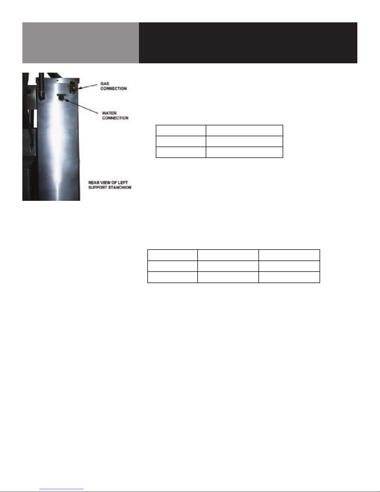
Gas and Water Connections are on the
back of the left stanchion.
Maximum Voltage Three Phase Current, Per Line
208 Volts
240 Volts
480 Volts
7 AMP
7 AMP
3.5 AMP
2. Water Connection(s)
Install a check valve in the incoming cold water line, if required by local plumbing
codes. Water pressure in the line should be between 30 and 60 PSIG (210 and 420
kPa). A ¾ NPT connector is needed to attach the water supply to the water inlet valve.
The minimum recommended water feed line diameter is ½ inch (13mm). Do not allow
the connection to leak, no matter how slowly. THE INSTALLER MUST PROVIDE THE
CHECK VALVE (ANTI-SYPHON DEVICE) IF REQUIRED BY LOCAL CODES.
3. Gas Connection
Connect 1 NPT gas line to the gas inlet valve on the rear of the left stanchion. Be sure
that the gas supply meets the following criteria:
Natural Gas Propane
Minimum
Maximum
7” W.C. 11” W.C.
10” W.C. 14” W.C.
OM-DH/INA/2-100 7
Page 8
Installation
WARNING
THIS UNIT IS FOR COMMERCIAL USE.
NEVER USE HOME OR RESIDENTIAL
GRADE GAS CONNECTIONS.
THEY DO NOT MEET GAS CODES AND
COULD BE HAZARDOUS.
WARNING
DO NOT ATTACH THE UNIT TO A TYPE “B”
VENT. FAILURE COULD RESULT IN FIRE OR
PROPERTY DAMAGE.
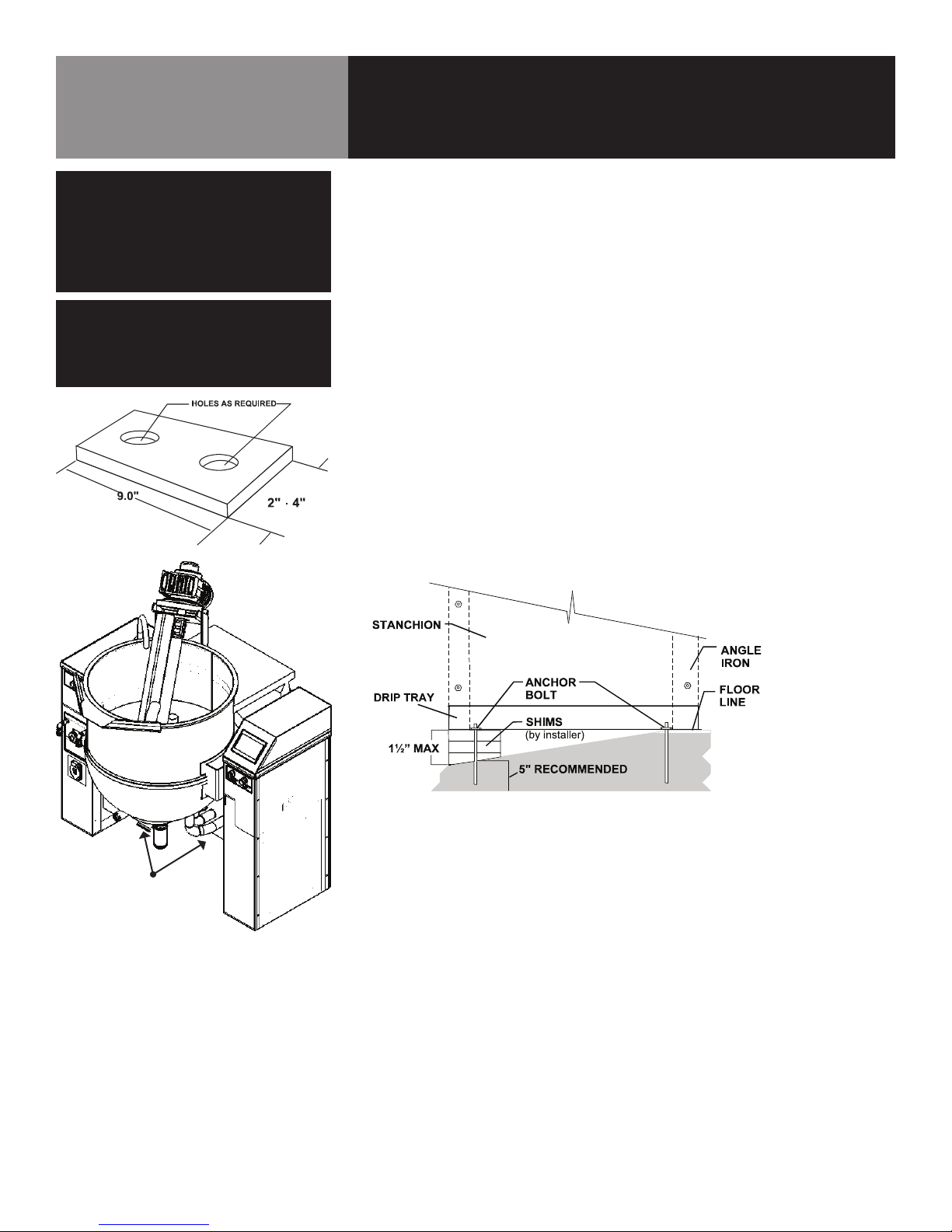
Recommended shim size.
The unit should be installed in a well-ventilated room on non-combustible flooring.
Anything which might obstruct or restrict the flow of air for combustion and ventilation
must be removed. The area directly around the appliance must be free of combustible
materials.
1. Installation requires connection with air, gas, water and electric services. See items
8 to 14 for details.
2. To protect the unit from damage, leave it on the shipping pallet until installation. When
ready to start installation, disassemble the shipping crate, unbolt the stanchions,
disconnect the shipping channels (braces) and raise the unit straight up off the skid.
Do not lift the kettle at the heat exchanger. Lifting the kettle at the heat exchanger
could damage the unit.
3. Install the unit with at least 22 inches clearance from the back walls. Also leave
enough room for easy cleaning, maintenance, and service.
4. Do not alter the kettle in any way. Any mechanical, electrical, or gas change must be
approved by the Groen Food Service Engineering Department.
5. Level the unit as follows:
The stanchions are each supplied with a drip tray in which the angle frame is placed.
Steel leveling shims (not included, supplied by installer) are placed between the drip
tray and frame so that the drip tray will be flush with the floor, as shown.
Don’t lift here
8 OM-DH/INA/2-100
Start with the right stanchion and level it as shown in the sketch. Once the right
stanchion is levelled and properly anchored front to rear, level the left stanchion front
to rear and side to side.
Level the entire unit side to side by placing a four foot carpenter’s level on the kettle
rim. Once the rim is level from side to side, rotate the level to check front to back.
Shim the left stanchion in the same manner as the right, and anchor the equipment
firmly to the floor through the shims.
6. Make sure the jacket water level is correct by confirming that it is in the middle of
the bulls-eye sight glass at the front of the kettle. If the water level is low, follow the
instructions under “Jacket Filling” in the “Maintenance” Section of this manual.
7. To protect personnel from steam coming from the safety valve, the open end of the
elbow at the outlet must be directed downward. If it is not, turn the elbow to the
correct position.
8. INSTALL:
Check valve in the incoming cold water line, if required by local plumbing codes, as
described in Paragraph 2, page 6.
Page 9
Installation
WARNING
DO NOT CONNECT ANY PIPING TO THE POP
SAFETY VALVE. IT MUST BE FREE TO VENT
STEAM AS NEEDED. THE ELBOW SHOULD
POINT DOWN TOWARD FLOOR. IMPROPER
INSTALLATION WILL VOID WARRANTY.
DANGER
ELECTRICALLY GROUND THE UNIT AT THE
TERMINAL PROVIDED. FAILURE TO
GROUND UNIT COULD CAUSE
ELECTROCUTION AND DEATH.
9. Provide electrical service per Paragraph 1, Electrical Supply Connecton in the
Inspection and Unpacking, Requirements Section, Page 6. Use ½ inch waterproof
conduit and waterproof connections. Observe local Codes and/or The National
Electrical Code in accordance with ANSI/NFPA 70 - latest edition. AN ELECTRICAL
GROUND IS REQUIRED. The electrical schematic is located on the inside of the
service panel. In Canada, provide electrical service in accordance with the Canadian
Electrical code, CSA C22.1 Part 1 and/or local codes.
10. The internal gas lines of the unit were cleaned and closed with a gas cock before
the unit was shipped from the factory. Ensure that external gas lines are free of lint,
dirt, metal chips, sealant, grease, oil or other contaminants, before you connect the
line to the kettle.
11. Connect the kettle gas cock to the gas service main using a 1” NPT gas connection.
12. Installation must conform with local codes, or in the absence of local codes, with
the National Fuel Gas Code, ANSI Z 223.1-1988 (or latest edition). The unit should be
installed in an well-ventilated room with a provision for adequate air supply. The best
ventilation will use a vent hood and exhaust fan with no direct connection between
the vent duct and the unit flue.
Do NOT obstruct the flue or vent duct after installation. In Canada, the installation
must conform with the CAN/CGA B149 Installation Codes for Gas Burning Appliances
and Equipment and/or local codes.
13. Adequate space for proper service and operation is required. Do NOT block any
air intake spacings to the combustion chamber or obstruct the air flow by piling or
stacking anything near the kettle.
14. After the kettle has been connected to the gas supply, all gas line joints must be
checked for leaks. DO NOT USE A FLAME TO CHECK FOR LEAKS. A thick soap solution
or other suitable leak detector should be used.
15. The appliance and its individual shutoff valve must be disconnected from the gas
supply piping system during any pressure testing of that system at test pressures
in excess of ½ PSIG (3.48 kPa). The appliance must be isolated from the gas supply
piping system by closing its individual manual shutoff valve during any testing of the
gas system at pressures equal to or less than ½ PSIG (3.48 kPa).
16. Check the following to confirm that your kettle has been installed properly:
• Enough room between the kettle and nearby objects for cleaning and service.
• Minimum clearance of 24 inches from sides and 24 from back.
• Unit vented to an exhaust hood.
• Kettle level.
• Correct amount of water in the jacket.
• Safety valve outlet pointed down.
• Connected with a waterproof electric power cable in accordance with Paragraph
1 Electrical Supply Connecton (above) and local electrical codes.
• Gas lines cleaned before connection.
• Gas connected with 1 NPT or larger.
• Gas line joints checked for leaks.
• No obstruction to air supply or venting.
• Gas lines (1 NPT) connected to supply.
• Water supply connection (¾”) completed.
OM-DH/INA/2-100 9
Page 10

Initial Start-Up
After the kettle has been installed, the installer should test to ensure that the unit is
operating correctly.
1. Remove all literature and packing materials from the inside and outside of the unit.
Clean out any material that might clog or damage the product outlet.
2. Add 50 gallons (180 liters) of water to the kettle to provide sufficient product for
testing.
3. Make sure the supplies of gas and electric power are on.
4. Following “Start Kettle Heating” instructions in the “Operating Instructions” section
of this manual, begin heating the water at the highest thermostat setting. The pilot
lamp should come on as soon as you pull out the emergency stop and turn on power.
Heating should continue until the water boils.
5. To turn off the unit, follow “To Stop Kettle Heating” in “Operating Instructions,” below.
If the kettle functions as described, it is ready for use. If the unit does not operate as
designed, contact an authorized Groen Service agent.
10 OM-DH/INA/2-100
Page 11

Operation
WARNING
ANY POTENTIAL USER OF THE EQUIPMENT
MUST BE TRAINED IN SAFE AND CORRECT
OPERATING PROCEDURES.
WARNING
KEEP AREA AROUND KETTLE FREE AND
CLEAR OF ALL COMBUSTIBLE MATERIALS.
CAUTION
HEATING AN EMPTY KETTLE MAY
CAUSE THE RELEASE OF STEAM FROM
THE SAFETY VALVE.
CONTROLS
Refer to the drawing on the following page for identification and function of kettle
controls.
OPERATING INSTRUCTIONS
Refer to the drawing on the following page for identification and function of kettle
controls.
1. CHECK THE WATER LEVEL IN THE JACKET EVERY DAY. The level must be in the middle
of the bulls-eye sight glass. If the level is low, see “Jacket Filling” in the “Preventive
Maintenance” section of this manual.
2. With the kettle cold, check the pressure gauge. If it does not show 20 or more inches
of vacuum (a reading of 20 to 30 below 0), see “Jacket Vacuum” in the “Preventive
Maintenance” section of this manual.
3. Start Kettle Heating
a. Open main gas supply valve.
b. Pull OUT the emergency stop and turn ON the control power switch on the front
of the right stanchion.
c. The touch-screen control panel should be ON (if not, check that mains power is
connected to the unit and the mains circuit breaker is on).
OM-DH/INA/2-100 11
Page 12
Operation
WARNING
DO NOT ATTEMPT TO LIGHT PILOT
MANUALLY WITH A FLAME.
4. Cooking Control
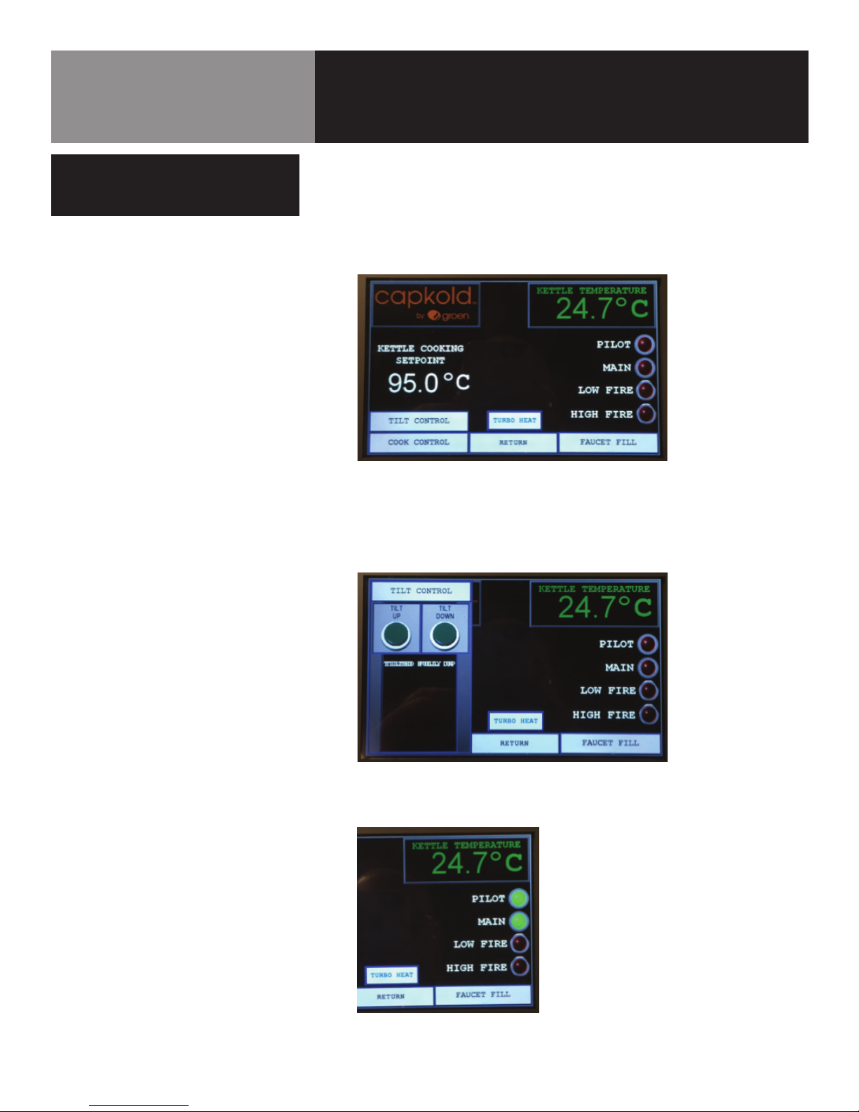
a. Touch the COOK CONTROL on the screen. The display will change to show the
main cooking control screen. This screen allows user to control kettle tilt, cooking
operation, water fill, turbo heat; and displays current product temperature in
degrees Celsius, desired cooking temperature in degrees Celsius; and lamp
status of the pilot, main gas vale, low fire burner and high fire burner.
b. Ensure kettle is tilted fully upright. If not, press TILT CONTROL on the screen.
The pop-up tilt control will appear. Press continuously on either TILT UP or TILT
DOWN until the kettle comes to a fully upright position. The tilt controls will turn
bright green when pressed and will go dark when released [Note: Press TILT
CONTROL to minimize the tilt feature on the screen.]
12 OM-DH/INA/2-100
c. The PILOT and MAIN indicators on the screen should show green.
d. Press FAUCET FILL on the screen. The pop-up faucet fill controls will appear.
Page 13

Operation
CAUTION
KEEP FLOORS IN FRONT OF KETTLE WORK
AREA CLEAN AND DRY. IF SPILLS OCCUR,
CLEAN IMMEDIATELY TO AVOID THE
DANGER OF SLIPS OR FALLS.
The kettle can be filled automatically or manually by tapping on the FILL control.
i. In the AUTO mode, tap on the WATER FILL SETPOINT – a display will appear
allowing you to select a desired quantity of Liters and enter them.
Tapping once on the START FILL control will initiate water fill through the
faucet. The control will turn bright green during the fill operation and go dark
once the fill setpoint is reached. Automatic fill can be interrupted by either
setting the FILL switch to MANUAL or pushing in an EMERGENCY STOP.
ii. In the MANUAL mode, press on the START FILL control and hold until the
desired quantity of water is delivered through the faucet. The TOTAL LITERS
counter can be used to observe manual fill operation – press the RESET
COUNTER to clear the indication before starting manual fill operation.
iii. Kettle must not be allowed to heat without at least 25% of its capacity of
product/water present. The rate-of-Rise feature will shut the kettle down if
there is insufficient product present during heating.
NOTE: Press FAUCET FILL to minimize the water fill feature on the screen.
OM-DH/INA/2-100 13
Page 14

Operation
e. Press COOK CONTROL on the screen. The pop-up cook controls will appear.
i. Tap on the COOK SETPOINT to bring up a key pad to select the desired
cooking temperature. Enter the numerical value in degrees Celsius and press
ENTER. The display should change to the selected value.
ii. Tap the COOK switch to turn ON or OFF the cook function. During the cook
function the burners will cycle to provide the necessary amount of heating
– during heat up to cook temperature, both the LOW FIRE and HIGH FIRE
burner indicators will indicate green – once the temperature approaches the
setpoint, the HIGH FIRE burner will shut off and the indicator will go dark.
NOTE: The BATCH CONTROL function is used in conjunction with an
externally located multi-channel electronic chart controller. Both the kettle
and the chart recorder have to be connected to an Ethernet router to allow
communications between devices. Setup and operation of the batch control
function are described in a separate manual.
14 OM-DH/INA/2-100
iii. The TEMPERATURE RATE OF RISE EXCEEDED!!! caution will appear on
screen and shut the unit down on both low and high fire. Add more water or
product to the kettle, press the ROR RESET to clear the lockout, and restart
the kettle cooking feature by switching the COOK switch to ON.
Page 15

Operation
WARNING
DO NOT STAND IN FRONT OF KETTLE
DURING TILTING. PRODUCT IS HOT AND
WILL CAUSE BURNS. EXERCISE EXTREME
CARE WHED HANDLING OR NEAR
HOT OR BOILING LIQUIDS.
f. Once the cooking setpoint is reached, the TURBO HEAT function can be used to
provide a short burst (factory preset at 30 seconds) of both high and low fire if
needed to fine tune the cooking function.
g. If mains power is interrupted during a cooking cycle, the kettle and display will
power up automatically, but the cook cycle will have to be re-started on the
COOK CONTROL pop-up display. All of the setting will have been preserved in
non-volatile memory, and will not have to be re-entered.
h. To turn off the cook process, tap the COOK switch on the COOK CONTROL
display to the OFF position. Both the LOW FIRE and HIGH FIRE indicators should
go dark.
i. To empty the kettle, first raise the cover, and then press the TILT DOWN button
on the TILT CONTROL display to slowly empty the kettle contents into suitable
capacity container(s).
5. Kettle Shut-Down
a. Clean the kettle thoroughly at the end of a cook cycle, making sure that all
surfaces are free of dirt and cooking material. Sanitize all cooking surfaces, let
dry and rinse clear.
b. Turn OFF the control power switch on the front of the right stanchion.
c. If the kettle will remain off for more than one day, turn off the mains power circuit
breaker switch.
20” to 30” of Vacuum (below 0 mark)
Top of the Window
(kettle tilted fully upright)
PRESSURE GAUGE/INDICATORS/WATER LEVEL
Check Vacuum and Water Level Daily
OM-DH/INA/2-100 15
Page 16

Emergency Stop Switch (Left)
HMI Controller
Operation
LEFT & RIGHT STANCHION CONTROLS
Control Power On/Off Switch
Emergency Stop Switch (Right)
16 OM-DH/INA/2-100
Page 17

Cleaning
OM-TD
another container, being sure to avoid
contact with hot product and hot basket
or. . .
f) Place basket with food on stable, at
surface, setting it inside a solid steamer
or bake pan, to catch any remaining hot
water which might drain from product.
c. Prepare a hot solution of the detergent/
cleaning compound as instructed by the
supplier.
OM-TD
OM-TD
another container, being sure to avoid
contact with hot product and hot basket
or. . .
f) Place basket with food on stable, at
surface, setting it inside a solid steamer
or bake pan, to catch any remaining hot
water which might drain from product.
c. Prepare a hot solution of the detergent/
cleaning compound as instructed by the
supplier.
OM-TD
WARNING
KEEP WATER AND SOLUTIONS OUT OF
CONTROLS AND ELECTRICAL EQUIPMENT.
DO NOT USE A HIGH PRESSURE HOSE TO
CLEAN THE CONTROL CONSOLE,
ELECTRICAL CONNECTIONS, ETC.
CAUTION
NEVER LEAVE A CHLORINE SANITIZER IN
CONTACT WITH STAINLESS STEEL
SURFACES FOR LONGER THAN 30
MINUTES. LONGER CONTACT CAN
MOST CLEANERS ARE HARMFUL TO THE
SKIN, EYES, MUCOUS MEMBRANES AND
CLOTHING. PRECAUTIONS SHOULD BE
CAUSE CORROSION.
CAUTION
TAKEN TO WEAR RUBBER GLOVES,
GOGGLES OR FACE SHIELD AND
PROTECTIVE CLOTHING. CAREFULLY
READ THE WARNINGS AND FOLLOW
LABEL DIRECTIONS.
Use a brush, sponge, cloth, plastic or
rubber scraper, or plastic wool to clean.
Don’t use metal implements
or steel wool when cleaning.
1. Suggested Cleaning Supplies:
a. A high quality detergent and sanitizer, or a combination cleaning-
sanitizing agent.
b. Kettle brushes in good condition.
c. Groen Spray Degreaser (PN 114801) or equivalent.
d. Groen De-limer/De-scaler (PN 114800) or equivalent.
e. A high quality stainless steel cleaner.
2. Precautions
Before any cleaning operation, turn off the burner system by setting the COOK
switch on the COOK CONTROL screen to the OFF position. Cut off electric power to
the unit by setting the CONTROL POWER switch to the OFF position.
3. Procedure
a. Clean food contact surfaces as soon as possible after use, preferably while the
kettle is still warm. If the unit is in continuous use, clean and sanitize inside and
outside at least once every 12 hours.
b. Scrape and flush out large amounts of food residues. Be careful not to scratch
the kettle with metal implements.
c. Prepare a solution of the detergent/cleaning compound as instructed by the sup-
plier. Clean the unit thoroughly. A cloth moistened with cleaning solution can be
used to clean controls, housing, electrical conduit, etc.
d. Rinse the kettle thoroughly with hot water. Then drain completely.
e. As part of the daily cleaning program, clean all inside and outside surfaces that
may have been soiled. Remember to check such parts as the underside of the
cover, control housing, etc.
f. To remove burned-on foods, use a brush, sponge, cloth, plastic or rubber scrap-
er, or plastic wool along with the cleaning solution. To reduce effort required in
washing, let the detergent solution sit in the kettle for a few minutes and soak
into the residue. Do NOT use abrasive materials or metal tools that might scratch
the surface. Scratches make the surface harder to clean and provide places for
bacteria to grow. Do not use steel wool, which will leave particles in the surface
and cause eventual corrosion and pitting.
g. The outside of the unit may be polished with a recognized stainless steel cleaner.
h. When the equipment needs to be sanitized, use a sanitizing solution equivalent
to one that supplies 100 parts per million chlorine. Obtain advice on the best
sanitizing agent from your supplier of sanitizing products. Following the suppliers instructions, apply the sanitizing agent after the unit has been cleaned and
drained. Rinse off the sanitizer thoroughly.
i. It is recommended that each piece of equipment be sanitized just before use.
j. If there is difficulty removing mineral deposits or a film left by hard water or food
residues, clean the kettle thoroughly and then use a deliming agent, like Groen
Delimer/Descaler (Part Number 114800), in accordance with the manufacturer’s
directions. Rinse and drain the unit before further use.
k. If cleaning problems persist, contact your cleaning product supplier for assis-
tance. The supplier has a trained technical staff with laboratory facilities to serve
you.
OM-DH/INA/2-100 17
Page 18

Maintenance
WARNING
AVOID ANY EXPOSURE TOTHE STEAM
BLOWING OUT OF THE SAFETY VALVE. SEVERE
BURNS CAN RESULT ON EXPOSED SKIN.
FAILURE TO CHECK SAFETY VALVE OPERATION
PERIODICALLY COULD RESULT IN PERSONAL
INJURY AND/OR DAMAGE TO EQUIPMENT.
WHEN TESTING, AVOID ANY EXPOSURE
TO THE STEAM BLOWING OUT OF THE
SAFETY VALVE. DIRECT CONTACT COULD
RESULT IN SEVERE BURNS.
This section describes actions the operator must take to maintain warranty coverage
and to keep the unit working safely and efficiently.
1. Jacket Vacuum/Removing Air from Jacket
Every day, while the kettle is cold, read the pressure/vacuum gauge. A positive
pressure reading or a vacuum reading between zero and 20 on the pressure/ vacuum
gauge indicates excess air in the jacket. Air in the jacket slows kettle heating and
can prevent the kettle from reaching operating temperature. To remove air:
a. Start the kettle. (See the “Operation” section of this manual).
b. Make sure the elbow on the outlet of the safety valve is turned so it will direct
escaping steam down toward the floor.
c. When the pressure/vacuum gauge reaches a positive pressure reading of five
PSI, release entrapped air and steam by lifting the safety valve lever for about
one second. Repeat this step, then let the valve lever snap back into the closed
position, so the valve will seat properly and not leak.
2. Test Safety Valve
At least twice a month, test the safety valve. Test the valve with the kettle operating
at 15 psi (105 kPa), by holding the test lever for at least five seconds. Then release
the lever and permit the valve to snap shut. If the lever does not activate, there is no
discharge, or the valve leaks, stop using kettle immediately and contact a qualified
factory service representative.
3. Jacket Filling
Every day, before you turn on the unit, make sure the water level is between the
marks on the water gauge glass. The jacket was filled at the factory with the proper
amount of treated water. From time to time, you may need to restore the water to
its proper level, either because water was lost as steam during venting or because
treated water was lost by draining. The procedure follows.
a. If you are replacing water lost as steam, use distilled water. Do not use tap water.
If you are replacing treated water that was drained from the jacket, prepare more
treated water first, as directed below.
b. Allow the kettle to cool completely. Remove the pipe plug from the jacket fill
assembly. Then open the gate valve and pour in the distilled or treated water.
Using a funnel will help you in this process. Hold the safety valve open while you
pour, to let air escape from the jacket. Continue adding water until the water level
rises to a point between the marks on the gauge glass.
c. Close the gate valve.
d. Air that gets into the jacket during the filling operation must be removed because
it will make heating less efficient. Follow the procedure in “Jacket Vacuum,”
above to restore a negative pressure reading.
18 OM-DH/INA/2-100
Page 19

Maintenance
WARNING
TO AVOID INJURY, READ AND FOLLOW ALL
PRECAUTIONS STATED ON THE LABEL OF
THE WATER TREATMENT COMPOUND.
4. Water Treatment
a. Fill a mixing container with the amount of water required (distilled water
preferred). The kettle requires 5½ gallons (20.4 liters).
b. Follow instructions. Apply to Groen water treatment kit part number 110324.
c. Hang a strip of pH test paper on the rim of the container, with about 1 inch of the
strip below the surface of the water.
d. Stir the water continuously, while you slowly add water treatment compound
until a color between indicating a pH of 10.5 and 11.5 is reached. (Shown on the
pH test kit chart.) Judge the pH by frequently comparing the test strip with the
color chart provided in the pH test kit.
e. Use a measuring cup to add the compound so that you may record the exact
amount used. The amount may be used again, if the same water sources and
compound are used in the future. However, it is best to check the pH each time
treated water is prepared.
5. Venting System
Periodically check the hood to make sure that nothing will block or hinder the free
flow of exhaust gases.
OM-DH/INA/2-100 19
Page 20

Maintenance
WARNING
AVOID ANY EXPOSURE TO THE STEAM
BLOWING OUT OF THE SAFETY VALVE. SEVERE
BURNS CAN RESULT ON EXPOSED SKIN.
A Service Log is provided at the rear of this manual. Each time service is performed on
this Groen equipment, enter the date on which the work was done, and who did it. Keep
this manual with the equipment.
1. Periodic Service
Periodic inspection will minimize equipment down time and increase efficiency of
operation. The following points should be checked regularly.
a. Every day, when the kettle is cold, the pressure/vacuum gauge should show a
vacuum of 20 to 30 inches. If it does not, see ”Jacket Vacuum” in the “Preventive
Maintenance” section of this manual.
b. Every day, the jacket water level must be in the middle of the bulls-eye sight
glass. If it is not, see “Jacket Filling” in the “Preventive Maintenance” section of
this manual.
c. Keep the primary air shutter of the burner gas jets free of dust and lint.
d. The pilot flame should be blue and should envelop about ½ inch of the flame
sensor tip.
e. Keep electrical wiring and connections in good condition.
f. Keep the inside of the control console clean and dry.
g. Keep the burner ports clean.
h. Keep the burner shield and adjacent parts clean.
i. Twice a month, check the safety valve to make sure that it works freely. When
gauge pressure is about 5 PSI, lift the valve lever enough to vent steam, then
quickly let it snap back into place.
2. Component Replacement
When replacement involves breaking a gas pipe connection, check the new
connection with soap solution or other appropriate leak detector.
DO NOT USE A FLAME TO TEST FOR LEAKS. Internal wiring is marked as shown on
circuit schematic drawings. Be sure that new components are wired in the same
manner.
20 OM-DH/INA/2-100
Page 21

Sequence of Operation
The following “action-reaction” outline is provided to help service personnel understand
how the unit functions for systematic troubleshooting and fault isolation.
When the operator turns the heat to “ON”, electric power at 120V is supplied to the
thermostat. The automatic gas control is then energized. Simultaneously, an electric
arc is established at the spark gap, and the automatic valve for the pilot burner opens.
When the electric spark ignites gas flowing from the pilot burner, a pilot flame probe
detects the flame. The probe sends a control signal that causes the spark to shut off and
a circuit to close for 24 V power.
The 24 V provides power for the heating indicator light and the main automatic valve.
Gas flowing from the main burner is ignited by the pilot flame. If a pilot flame is not
sensed within 60 seconds after the spark, a timer shuts down the whole operation.
As heat from the main burner brings the temperature of steam in the jacket up to
the thermostat setting, the thermostat switch opens. With electric power cut off, the
main burner valve closes and turns off the burner. When jacket steam cools below the
thermostat set point, the thermostat switch closes and begins another heating cycle.
On-off cycling continues to maintain the kettle at the desired temperature.
The thermostat controls heating by alternately calling for flames at the full capacity of
the main burner or signaling the control to shut the burner completely off. Because the
control works in this “all or nothing” way, the kettle will heat as fast as it can until it
reaches the set temperature, no matter what that temperature is.Turning the thermostat
dial to a higher setting will cause heating to continue longer, until the kettle reaches the
higher temperature, but it cannot make the unit heat any faster.
The unit is equipped with a Pressure Limit Switch, Low Water Cut-Off and a Safety
Valve. These safety features operate as follows:
1. Pressure limit switch: If jacket steam pressure exceeds 43 PSI, the switch opens and
breaks the electrical circuit to the main gas valve solenoid coil. The valve closes and
stays closed until jacket pressure decreases to 44 PSI. The pressure limit switch
then closes, energizes the gas valve coil, and allows operation to resume.
2. Low-water cutoff: As long as steam jacket water touches the cutoff electrode, kettle
operation can continue. If the water falls below the end of the electrode, an electrical
control circuit is broken, and the main gas valve closes. Jacket water must be
restored to a safe operating level before the kettle can be heated again.
3. Safety valve: If steam pressure in the jacket reaches 50 PSI, the valve will open and
relieve the excess pressure.
OM-DH/INA/2-100 21
Page 22

Troubleshooting
Your Groen kettle is designed to operate smoothly and efficiently if properly maintained. However, the following is a list of checks to
make in the event of a problem. Wiring diagrams are furnished inside the service panel. X indicates items which must be performed
by an authorized technician.
WARNING
BEFORE REPLACING ANY PARTS, DISCONNECT THE UNIT FROM THE ELECTRIC POWER SUPPLY AND
CLOSE THE MAIN GAS VALVE. ALLOW FIVE MINUTES FOR UNBURNED GAS TO VENT.
CAUTION
USE OF ANY REPLACEMENT PARTS OTHER THAN THOSE SUPPLIED BY GROEN OR THEIR AUTHORIZED DISTRIBUTOR CAN
CAUSE INJURY TO THE OPERATOR AND DAMAGE TO THE EQUIPMENT AND WILL VOID ALL WARRANTIES.
SYMPTOM WHO WHAT TO CHECK
Kettle continues heating
after it reaches desired
temperature.
Kettle stops heating before
it reaches the desired
temperature.
Pilot burner and/or burner
will not light or goes out
after working for a while.
Kettle heats slowly. User a.
User a.
User a. That the temperature controller setting is correct.
b. That the Heat on/o switch is ON.
c. Reading of the pressure/vacuum gauge. If it is not 20 to 30
User a. That the main gas valve is open (handle is in line with the gas
b. That the Heat on/o switch is ON.
c. That the temperature controller is at the correct setting.
d. Use the “Start Kettle Procedure.” See the manual’s “Operation”
e. Jacket water level. If it is low, see “Jacket Filling” in the
f. That electric power is turned on at the circuit breaker or fuse
g. Gas supply to your building.
h. Is steam trap working?
That the temperature controller is correct.
below zero when the kettle is cold, see “Jacket Vacuum” in the
“Preventive Maintenance” section of this manual.
pipe)
Section.
“Preventive Maintenance” section of this manual.
box, and that power is being supplied to your building.
Reading of the pressure/vacuum gauge. If not 20 to 30 below
zero when the kettle is cold, see “Jacket Vacuum” in the
“Preventive Maintenance” section of this manual.
Authorized
Service Rep Only
Safety valve pops. User a.
22 OM-DH/INA/2-100
b. Check operation of pressure limit switch. X
Reading of the pressure/vacuum gauge. If it is not 20 to 30
below zero when the kettle is cold, see “Jacket Vacuum” in the
“Preventive Maintenance” section of this manual.
Page 23

Troubleshooting
System does not produce a
spark.
Spark is present but the
pilot will not light.
Pilot lights, but main burner
will not come on, and
spark does not stay on.
Authorized
Service Rep Only
Authorized
Service Rep Only
Authorized
Service Rep Only
a. Thermostat, and close the contacts if they are open. X
b. AC voltage between terminals “2” and “GR”. If it is not 24 Volt:
(1) Check high limit switch, which should be closed. X
(2) Replace the transformer. X
c. Pilot spark gap. Regap, if it is not 7/64 inch. X
d. Pilot electric ceramic for crack or break. X
e. That the high tension cable is rmly attached and in good
condition. If cracked or brittle, replace the pilot. X
f. Replace the electronic portion of the G60 electronic system. X
That the pilot valve is securely connected to terminals “1” and
a.
“GR”. Some models have the pilot valve grounded internally. X
b. That gas pressure meets the control manufacturer’s
specications. X
c. For gas at the pilot. If it is not owing:
(1) Check the pilot gas line for kinks and obstructions. X
(2) Replace the pilot valve. X
d. That the pilot spark gap is 7/64 inch and located in the pilot gas
stream. If not, adjust or replace the pilot. X
e. Pilot orice, and clean, if necessary. X
f. For drafts. Shield the pilot burner, if necessary. X
a. For 24 V between terminals “3” and “GR”. If voltage is not
correct, replace the G60 electronics. X
b. That the gas pressure meets the control manufacturer’s
specications. X
c. Electrical connections to the main valve to terminals “3” and
“GR”, to assure that they are securely attached. If they are,
replace the main valve.”
Pilot lights, but main burner
will not come on, the spark
stays on.
Authorized
Service Rep Only
Sensor cable, to make sure of secure and attachments to the
a.
sensor and to terminal “4” the G60. X
b. That the cable is not grounded. If it is, correct the ground fault. X
c. Cable for continuity and insulation condition. X
d. Sensor ceramic for cracks. X
e. That sensor probe current is less than 0.7 microamp, by
disconnecting the sensor cable from terminal “4” and
connecting a DC microammeter between the sensor cable
terminal and terminal “4”. If the current is equal to or greater
than 0.7 microamp, replace the G60 electronics. X
If the current is less than 0.7 microamp:
(1) Check the gas pressure. X
(2) Clean the pilot assembly. X
(3) Tighten mechanical and electrical connections. X
f. Pilot application and correct to increase sensor probe current,
by:
(1) Increasing or decreasing pilot orice size. X
(2) Shielding the pilot from drafts. X
OM-DH/INA/2-100 23
Page 24

172194
KETTLE BODY ASSEMBLY
Location Function or Connection
A LEFT TRUNNION
B RIGHT TRUNNION
C POUR LIP
D WELL AND COUPLING FOR RTD
E WATER LEVEL SIGHT GLASS
F HEAT EXCHANGE FIN-TUBES
G COUPLING FOR WATER LEVEL PROBE
H COUPLING FOR TEMPERATURE PROBE
I ASME DATA PLATE
Ref Description Part #
- LABEL, DISTILLED WATER Z026450
Parts List
- PROBE, TEMPERATURE, 6” LONG 115369
- VALVE, SAFETY, 50 PSI, ¾ NPT Z005587
- ASSEMBLY, WATER FILL 115372
- ELBOW, 90 DEGREE, ¾ NPT Z010668
- ASSEMBLY, PLATE & CHAIN Z8832
ASSEMBLY, FAUCET BRACKET&
SPOUT
FLUE STACK/COMBUSTION
CHAMBER ASSEMBLY
115247
149665
24 OM-DH/INA/2-100
Page 25

172278
LEFT STANCHION ASSEMBLY
Ref Description Part #
1
NIPPLE, 1 NPT, 7" LONG
2
NIPPLE, 1 NPT, 21" LONG
3
ELBOW, 90 DEGREE, 1" NPT
ELBOW, 90 DEGREE, 3/4 NPT, SS
4
5
NIPPLE, 3/4 NPT, 6-1/2" LONG, SS
HOSE, WATER FILLER
6
7
ADAPTER, SWIVEL, 3/4 NPT, SS
8
ADAPTER, 3/4 NPT, SS
ASSEMBLY, WATER PIPING
9
10
NIPPLE, 1 NPT, 15-1/2" LONG
JOINT, SWIVEL, 1 NPT, (GAS)
11
12
COUPLING, FULL, 1 NPT
13
BLOCK, PILLOW
BEARING, BRONZE
14
16
NUT, HEX, KEPS, 1/4-20
17
SCREW, HEX HEAD, 1/2-13, 2" LONG
18
NUT, HEX, 1/2-13
SCREW, SET, CUP POINT, 3/8-16, 5/8" LONG
19
20
SET COLLAR, 3" TRUNNION
21
FITTING, GREASE, STRAIGHT, 1/4 NPT
22
NIPPLE, 3/4 NPT, 12" LONG
23
COUPLING, FULL, 1 NPT
SCREW, TRUSS HEAD, 10-32, 1/2" LONG
24
25
COVER, STANCHION, LEFT SIDE
ASSEMBLY, INNER CLADDING, STANCHION,
26
LEFT SIDE
27
LABEL, NATURAL GAS
27
LABEL, PROPANE GAS
ASSEMBLY, OUTER CLADDING,
28
STANCHION, LEFT SIDE
GASKET, 1/16 X 1, NEOPRENE, CLOSED
29
CELL, 7' LONG
30
ASSEMBLY, FRAME, LEFT STANCHION
LABEL, WATER IN
31
32
ASSEMBLY, FRAME, POWER COVER
GASKET, NEOPRENE, 9-1/2 X 9-1/2,
33
FRAME TOP
35
NIPPLE, CLOSE, 1 NPT
ASSEMBLY, FRAME, LEFT SIDE
36
-
BOLT, HEX, 3/8-16, 1-1/4" LONG
-
NUT, HEX, 3/8-16
-
WASHER, FLAT, 3/8
40
SWITCH, EMERGENCY STOP
WASHER, LEVELING
-
42
BRACKET, KETTLE SHROUD
- NUT, ACORN, 1/4-20 Z090567
44 OVERLAY, EMERGENCY STOP 115317A
Z002490
Z014018
Z010006
Z009802
Z006230
Z014019
Z010230
Z012940
Z083944
Z003565
Z012060
Z009547
Z010230
Z072189
Z087993
Z087992
Z040232
Z005517
FA BLT0101
FA NUT0341
Z005830
Parts List
172466
115284
115283
172474
115275
115225
115268
115239
133409
172383
172267
172265
115336
172360
172366
172365
172360
N87527
172280
115310
OM-DH/INA/2-100 25
Page 26

172474
WATER PIPING ASSEMBLY
Ref Description Part #
ELBOW, STREET, 90 DEGREE, 3/4
1
NPT, SS
2
ELBOW, 90 DEGREE, 3/4 NPT, SS
3
NIPPLE, 3/4 NPT, 2" LONG, SS
4
NIPPLE, 3/4 NPT, 4" LONG, SS
METER, WATER, {MEASURES IN
5
GALLONS)
METER, WATER, [MEASURES IN
5
LITERS]
6
VALVE, SOLENOID, WATER, 24VDC
172471
172473
172472
172470
Z055211
Z098369
172475
Parts List
26 OM-DH/INA/2-100
Page 27

172378
GAS VALVE PIPING, PRESSURE GAUGE
AND BOX ASSEMBLY
Ref Description Part #
1
GASKET, CLOSED CELL, NEOPRENE
2
CAP, PROBE, WATER LEVEL
3
FITTING, PROBE, WATER LEVEL
ASSEMBLY, PIPING, GAS
4
6
COVER, ENCLOSURE, GAS VALVE
SCREW, TRUSS HEAD, 10-32 X 1/2"
7
LONG
8
NUX, HEX, 8-32
SCREW, CAP, HEX HEAD, 1/4-20 X
9
1/2" LONG
10
NUT, HEX, 1/4-20
11
COVER, ENCLOSURE, WATER LEVEL
ENCLOSURE, WATER LEVEL
13
ASSEMBLY, PIPING, PRESSURE
14
SWITCH & GAUGE
15
UNION, 3/8 NPT
16
GROMMET, 11/16 ID
17
GROMMET, 9/16 ID
18
GROMMET, 7/8 ID
19
GROMMET, 1/4 ID
20
GROMMET, STRAIN RELIEF
22
LIGHT, INDICATOR, RED, 24VAC
23
OVERLAY, OPERATING PRESSURE
GRIP, CORD, 1/2 NPT
25
FITTING, COMPRESSION, STRAIGHT,
26
3/8 NPT - 3/8 TUBE
FITTING, COMPRESSION, 90 DEGREE,
27
3/8 NPT - 3/8 TUBE
28
TUBING, COPPER, 3/8 OD, 12" LONG
29
CONNECTOR, 90 DEGREES, 1/2 NPT
30
PROBE, WATER LEVEL
MODULE, IGNITION, INTERMITTENT
31
PILOT
32
CONDUIT, GAS PIPING
GASKET, CONDUIT
33
34
RIVNUT, OPEN END, 10-32
-
CONDUIT, SEALTITE, 1/2"
TUBING, ALUMINUM, 1/4 OD, 36"
37
LONG
CABLE, HIGH VOLTAGE, IGNITION, 36"
38
LONG
39
WIRE HARNESS, MAIN
40
NUT, CONDUIT, 1/2 NPT
41
ENCLOSURE, GAS VALVE
GROMMET, SILICONE, 11/16 ID
-
-
TEE, 1/2 NPT
NIPPLE, CLOSE, 1/2 NPT
-
48
COUPLING, 1/2 RECESSED, 1/4 NPT
115336
115319B
146992
149650
115294
Z072189
Z011030
Z005608
Z005601
115290
172377
172376
Z027421
Z007245
Z074974
Z007400
Z001518
Z088239
116383
115317D
Z009196
117801
117802
Z007332
Z001668
Z076526
Z085153
115234
115299
113235
Z001697
Z006796
Z096728
115335
Z008808
115292
128863
Z013650
Z004306
Z004158
Parts List
OM-DH/INA/2-100 27
Page 28

172376
PRESSURE SWITCH AND GAUGE
PIPING ASSEMBLY
Ref Description Part #
1
PRESSURE SWITCH, SET AT 43 PSI
2
TEE, 1/4 NPT
3
PRESSURE SWITCH, SET AT 43 PSI
ELBOW, 90 DEGREE, 1/4 NPT
4
5
NIPPLE, 1/4 NPT, 1" LONG
NIPPLE, 1/4 NPT, 6-1/2" LONG
6
7
UNION, STRAIGHT, 1/4 NPT
8
NIPPLE, 1/4 NPT, 2"LONG
BUSHING, REDUCING, 3/8 NPT - 1/4
9
NPT
10
TEE, 3/8 NPT
11
NIPPLE, 3/8 NPT, 10" LONG
12
ELBOW, STREET, 90 DEGREE, 3/8 NPT
13
NIPPLE, 3/8 NPT, 6" LOG
17
ELBOW, 90 DEGREE, 3/8 NPT
GAUGE, PRESSURE
18
FITING, STRAIGHT, COMPRESSION,
19
1/4 NPT - 1/4 TUBE
20
NIPPLE, 3/8 NPT, 1-1/2" LONG
21
NIPPLE, 3/8 NPT, 1" LONG
22
TUBING, COPPER, 1/4, 24" LONG
NIPPLE, 3/8 NPT, 4" LONG
Z096963
Z008539
Z096963
Z005682
Z005683
Z003674
Z005126
Z005675
Z059907
Z012794
Z012794
Z009853
Z005752
Z055335
115293
Z064565
Z005678
Z007439
116002
Z005720
Parts List
28 OM-DH/INA/2-100
Page 29

149650
GAS VALVE PIPING ASSEMBLY
Ref Description Part #
1
UNION, STRAIGHT, 1 NPT
2
NIPPLE, CLOSE, 1 NPT
3
ELBOW, REDUCING, 1 NPT X 3/4 NPT
VALVE, GAS, MAIN
4
5
NIPPLE, CLOSE, 3/4 NPT
VALVE, GAS, SOLENOID, 3/4 NPT
6
TEE, REDUCING, 3/4 NPT X 3/4 NPT
7
X 1/2 NPT
8
NIPPLE, 3/4 NPT, 4" LONG
9
ELBOW, 3/4 NPT
ELBOW, REDUCING, 3/4 NPT X 1/2
10
NPT
11
NIPPLE, 1/2 NPT, 4" LONG
12
UNION, STRAIGHT, 1/2 NPT
13
NIPPLE, 1/2 NPT, 2" LONG
BUSHING, REDUCING, 1/2 NPT X 1/4
14
NPT
15
NIPPLE, 1/4 NPT, 2" LONG
16
UNION, STRAIGHT, 1/4 NPT
17
NIPPLE, 1/4 NPT, 3-1/2" LONG
18
ELBOW, 90 DEGREE, 1/2 NPT
19
NIPPLE, 1/2 NPT, 1-1/2" LONG
Z005534
Z005517
Z003610
115298
Z008238
108963
Z005484
Z005554
Z008124
Z008751
Z005554
Z004186
Z005551
Z008739
Z005675
Z005126
Z041509
Z008747
Z004184
Parts List
OM-DH/INA/2-100 29
Page 30

172361
RIGHT STANCHION ASSEMBLY
Parts List
Ref Description Part #
1
COVER, STANCHION, RIGHT SIDE
ASSEMBLY, FRAME, RIGHT
2
STANCHION
ASSEMBLY, OUTER CLADDING,
3
STANCHION, RIGHT SIDE
ASSEMBLY, INSIDE CLADDING,
4
STANCHION, RIGHT SIDE
SUBASSEMBLY, ELECTRICAL
5
COMPONENTS
ASSEMBLY, ENCLOSURE,
6
CONTROL PANEL
7
MOTOR, DRIVE, 1/2 HP
8
NUT, HEX, KEPS, 1/4-20
9
GEAR, 72 TOOTH
10
ASSEMBLY, MECHANICAL STOP
SCREW, CAP, SOCKET, 5/16-18,
11
2" LONG
12
COUPLING, SHAFT
13
NUT, HEX 1/2-13
172384
172293
172265
172294
172393
172390
128973
NT1101
115269
115240
115302
115276
Z003565
Ref Description Part #
FITTING, GREASE, STRAIGHT,
16
1/4 NPT
CASTING, TRUNNION GEAR
17
CARRIER
18
COLLAR, SET, 1" ID
SCREW, SET, CUP POINT, 3/8-16,
19
5/8" LONG
20
SHAFT, DRIVE
21
KEY, 1/4" SQUARE, 3-1/4" LONG
22
BEARING, ROLLER, 1"
23
GEAR, WORM
HMI, TOUCH SCREEN
24
CONTROLLER
ASSEMBLY, TILT SWITCH &
25
HARNESS
SCREW, TRUSS HEAD, 8-32,
26
3/8" LONG
BAR, 1/2" SQUARE, SS, 3-1/2"
27
LONG
28
KEY, 1/4" SQUARE, 2" LONG
Z009547
Z012222
Z012012
Z012060
115242
Z012468
Z012036
Z012054
172292
115282
Z005764
303208
Z009258
Ref Description Part #
WASHER, SHIM, 1-3/4 OD,
31
0.001" THICK
WASHER, SHIM, 1-3/4 OD,
32
0.003" THICK
WASHER, SHIM, 1-3/4 OD,
33
0.005" THICK
34
WASHER, FLAT, 3/8, SS
35
WASHER, LOCK, SPLIT, 3/8
36
NUT, HEX, 5/16-18
37
BLOCK, STOP, MECHANICAL
SCREW, SAP, HEX HEAD, 5/16-
38
18, 1-1/2" LONG
39
WASHER, FLAT, 5/16
40
WASHER, LOCK, 5/16
SCREW, CAP, HEX HEAD, 1/2-13,
41
2-1/2" LONG
42
PLATE, SHIP, TILT MOTOR
43
ASSEMBLY, SWITCH, 2 POSITION
Z012192
Z012193
Z012079
Z005830
Z005618
Z005602
115213
Z006017
Z012093
Z005658
Z005629
172272
115337A
14
RIVNUT, OPEN END, 10-32
SCREW, TRUSS HEAD, 10-32,
15
1/2" LONG
113235
Z072189
30 OM-DH/INA/2-100
SCREW, CAP, HEX, 3/8-16,
29
1-1/2" LONG
GASKET, NEOPRENE, CLOSED
30
CELL, 90-INCHES
Z005615
115336
44
SWITCH, EMERGENCY STOP
OVERLAY, POWER AND
45
EMERGENCY STOP
N87527
172398
Page 31

172476
ELECTRICAL SUBPANEL ASSEMBLY
Ref Description Part #
1
PLC, 1763-L16DWD
2
ANALOG OUTPUT, 1762-IR4
ETHERNET SWITCH, EKI-2525 AE 5
3
PORT
4
24 VDC POWER SUPPLY, MDR-120-24
3A CIRCUIT BREAKER, FAZ-C3/2-NA
5
UL 489 3A
1A CIRCUIT BREAKER, FAZ-C1/1SP UL
6
1077 1A
2A CIRCUIT BREAKER, FAZ-C2/1SP UL
7
1077 2A
5A CIRCUIT BREAKER, FAZ-C5/1SP UL
8
1077 5A
9
75 VA TRANSFORMER, PH75MLI 75VA
10
1.5A FUSE, ATDR1.5
172520
172521
172522
172523
172524
172525
172526
172527
172528
172529
Parts List
11
10A FUSE, ATMR10
12
FUSE HOLDER, US3J31
13
CONTACTOR, MC-9B-DC24-11S
14
CONTACTOR, MC-9B/R-DC24-22S
ON / OFF CONTROL WITH LOCKOUT,
15
MMS-32H-2.5 BRK/OL
16
RELAY, AB 700-HLT12U24
TERMINAL, 1492-J3-W 600VOLT 25
19
AMP
TERMINAL, 1492-JG3-IEC 600VOLT
20
GND
21
LOW WATER CUTOFF, PN 26B3B
- PANEL, ELECTRICAL MOUNT 172296
- NUT, HEX, 1/4-20 Z005601
172530
172531
172532
172533
172534
172535
172536
172537
172538
OM-DH/INA/2-100 31
Page 32

115282
TILT SWITCH ASSEMBLY
Ref Description Part #
SWITCH, OVERTRAVEL,
1
PLUNGER TYPE
2
BRACKET, TILT SWITCH
3
HARNESS, TILT SWITCH
115261
115221
115281
Parts List
32 OM-DH/INA/2-100
Page 33

HIGH FIRE BURNER ASSEMBLY
Ref Description Part #
1
MANIFOLD, BURNER, 40-PORT
2
NIPPLE, 1/2 NPT, 3-1/2" LONG
BUSHING, REDUCING, 1/2 NPT TO
3
1/8 NPT
BURNER JET, BRASS, 7/16-24 NS,
4
#654
5
PLUG, PIPE, RECESSED HEX, 1/8 NPT
BURNER JETS, BRASS, 7/16-24 NS
Ref
N02
N24
N46
N68
N810
L02
L24
L46
L68
L810
Elevation - Jet Orifice Size
NATURAL GAS
0-2000' ELEVATION -- 1.15MM
(0.0453)
2001-4000' ELEVATION -- 1.05MM
(0.0413)
4001-6000' ELEVATION -- 1.05MM
(0.0394)
6001-8000' ELEVATION -- 0.95MM
(0.0374)
8001-10000' ELEVATION -- 0.89MM
(0.0350)
LP GAS
0-2000' ELEVATION -- 0.79MM
(0.0310)
2001-4000' ELEVATION -- 0.71MM
(0.0280)
4001-6000' ELEVATION -- 0.70MM
(0.0276)
6001-8000' ELEVATION -- 0.65MM
(0.0256)
8001-10000' ELEVATION -- 0.61MM
(0.0240)
146985
Z008227
Z088290
SEE
ELEVATION
TABLE
Z010286
Part #
127554
106159
127560
174293
127361
102944
127563
174292
154178
104291
Parts List
OM-DH/INA/2-100 33
Page 34

LOW FIRE BURNER ASSEMBLY
Ref Description Part #
1
MANIFOLD, BURNER, 20-PORT
2
NIPPLE, 1/2 NPT, 3-1/2" LONG
BUSHING, REDUCING, 1/2 NPT TO
3
1/8 NPT
146986
Z008227
Z088290
Parts List
4
NIPPLE, 1/2 NPT, 1-1/2" LONG
BURNER JET, BRASS, 7/16-24 NS,
5
#654
6
PLUG, PIPE, RECESSED HEX, 1/8 NPT
BURNER JETS, BRASS, 7/16-24 NS
Ref
N02
N24
N46
N68
N810
L02
L24
L46
L68
L810
Elevation - Jet Orifice Size
NATURAL GAS
0-2000' ELEVATION -- 1.15MM
(0.0453)
2001-4000' ELEVATION -- 1.05MM
(0.0413)
4001-6000' ELEVATION -- 1.05MM
(0.0394)
6001-8000' ELEVATION -- 0.95MM
(0.0374)
8001-10000' ELEVATION -- 0.89MM
(0.0350)
LP GAS
0-2000' ELEVATION -- 0.79MM
(0.0310)
2001-4000' ELEVATION -- 0.71MM
(0.0280)
4001-6000' ELEVATION -- 0.70MM
(0.0276)
6001-8000' ELEVATION -- 0.65MM
(0.0256)
8001-10000' ELEVATION -- 0.61MM
(0.0240)
Z004184
SEE
ELEVATION
TABLE
Z010286
Part #
127554
106159
127560
174293
127361
102944
127563
174292
154178
104291
34 OM-DH/INA/2-100
Page 35

AGITATOR ASSEMBLY
Ref Description Part #
1
DISC, 1e DIAMETER X 10 GA (2)
2
COUPLING, QUICK DISCONNECT
3
BLADE, SCRAPER (6)
4
HOLDER SCRAPER BLADE (6)
019058
012719
005098
005099
Parts List
SCRAPER LOCKING PIN (NOT SHOWN)
-
5
LOCKING HAIRPIN CLIP (6)
7
YOKE, BLADE CARRIER (6)
003655
003652
004923
OM-DH/INA/2-100 35
Page 36

LOW FIRE BURNER ASSEMBLY
Ref Description Part #
1
REGULATOR, AIR
2
NIPPLE, 1/4” X CLOSE BRASS
3
TEE, 1/4” BRASS
4
COUPLING, FULL 3/8”
5
FITTING COMPRESSION
CONNECTION HOSE 3/8” X 65” (NOT
6
SHOWN)
7
ELBOW, 90 STREET 3/8”
8
DISCONNECT, QUICK 3/8”
9
ELBOW, 90 STREET 1/4”
FILTER, AIR, IN LINE PARKET #
10
4M-F4L-10-BN-B
FITTING COMP, 3/8” T X 1/4” P 90
11
DEG FEMALE ELBOW
CONNECTOR MALE 3/8” MPT X 3/8”
13
TUBE
050119
003923
014360
012740
091940
155102
055336
N71392
010232
069038
057218
050879
Parts List
36 OM-DH/INA/2-100
Page 37

Wiring Diagram
OM-DH/INA/2-100 37
Page 38

Wiring Diagram
38 OM-DH/INA/2-100
Page 39

Service Log
Model No: Purchased From:
Serial No: Location:
Date Purchased: Date Installed:
Purchase Order No: For Service Call:
Date Maintenance Performed Performed By
OM-DH/INA/2-100 39
Page 40

1055 Mendell Davis Drive • Jackson MS 39272
888-994-7636 • 601-372-3903 • Fax 888-864-7636
unifiedbrands.net
© 2018 Unified Brands. All Rights Reserved. Unified Brands is a wholly-owned subsidiary of Dover Corporation.
PART NUMBER 176302, REV. A (01/18)
 Loading...