

Page 1
OPERATOR/SERVICE MANUAL
IMPORTANT INFORMATION, KEEP FOR OPERATOR
This manual provides information for:
MODELS
BPM-30/40E(CE) International
ECLIPSE™ ERGONOMIC
TILTING BRAISING PAN
· Stainless Steel
· Manual Tilt
· Electric Heated
THIS MANUAL MUST BE RETAINED FOR FUTURE REFERENCE.
READ, UNDERSTAND AND FOLLOW THE INSTRUCTIONS AND
WARNINGS CONTAINED IN THIS MANUAL.
FOR YOUR SAFETY
Do not store or use gasoline or other flammable vapors
and liquids in the vicinity of this or any other appliance.
WARNING
Improper installation, adjustment, alteration, service or
maintenance can cause property damage, injury or death.
Read the installation, operating and maintenance instructions
thoroughly before installing or servicing this equipment.
NOTIFY CARRIER OF DAMAGE AT ONCE
It is the responsibility of the consignee to inspect the container upon receipt of
same and to determine the possibility of any damage, including concealed damage. Unified Brands suggests that if you are suspicious of damage to make a
notation on the delivery receipt. It will be the responsibility of the consignee to file
a claim with the carrier. We recommend that you do so at once.
Manufacture Service/Questions 888-994-7636.
Information contained in this document is known to be current and accurate at the time
of printing/creation. Unified Brands recommends referencing our product line websites,
unifiedbrands.net, for the most updated product information and specifications.
PART NUMBER 153352, REV. A (3/07)
1055 Mendell Davis Drive
Jackson, MS 39272
888-994-7636, fax 888-864-7636
groen.com
Page 2

IMPORTANT — READ FIRST — IMPORTANT
THESE APPLIANCES MUST BE INSTALLED BY A COMPETENT PERSON IN CONFORMITY WITH THE
INSTALLATION AND SERVICING INSTRUCTIONS AND NATIONAL REGULATIONS IN FORCE AT THE TIME.
PARTICULAR ATTENTION MUST BE PAID TO THE FOLLOWING:
I. E. E. REGULATIONS FOR ELECTRICAL INSTALLATIONS
ELECTRICITY AT WORK REGULATIONS
HEALTH AND SAFETY AT WORK ACT
FIRE PRECAUTIONS ACT
LOCAL AND NATIONAL BUILDING REGULATIONS
USERS SHOULD BE CONVERSANT WITH APPROPRIATE PROVISIONS OF THE FIRE PRECAUTIONS
ACT. IN PARTICULAR THEY SHOULD BE AWARE OF THE NEED FOR REGULAR SERVICING BY A
COMPETENT PERSON TO ENSURE CONTINUED SAFE AND EFFICIENT APPLIANCE PERFORMANCE.
WARNING: TO PREVENT SHOCKS, ALL APPLIANCES WHETHER GAS OR ELECTRIC, MUST BE
EARTHED. FAILURE TO EARTH BRAISING PAN COULD RESULT IN ELECTROCUTION
AND DEATH.
ON COMPLETION OF THE INSTALLATION, THESE INSTRUCTIONS SHOULD BE LEFT WITH THE
ENGINEER-IN-CHARGE FOR REFERENCE DURING SERVICING. FURTHER TO THIS, THE USERS
INSTRUCTIONS SHOULD BE HANDED TO THE USERS AND THE INSTALLER SHOULD INSTRUCT THE
RESPONSIBLE PERSON(S) IN THE CORRECT OPERATION AND MAINTENANCE OF THE APPLIANCE.
THIS EQUIPMENT IS ONLY FOR PROFESSIONAL USE AND SHALL BE OPERATED BY QUALIFIED
PERSONS. IT IS THE RESPONSIBILITY OF THE SUPERVISOR OR EQUIVALENT TO ENSURE THAT USERS
WEAR PROTECTIVE CLOTHING, AND TO DRAW ATTENTION TO THE FACT THAT SOME PARTS WILL, BY
NECESSITY, BECOME VERY HOT AND WILL CAUSE BURNS IF TOUCHED ACCIDENTALLY.
UNLESS OTHERWISE STATED, PARTS WHICH HAVE BEEN PROTECTED BY THE MANUFACTURER ARE
NOT TO BE ADJUSTED BY THE INSTALLER.
CAUTION: SHIPPING STRAPS ARE UNDER TENSION AND CAN SNAP BACK WHEN CUT.
WARNING :BEFORE ATTEMPTING ANY SERVICING, ENSURE THAT THE ELECTRICAL SUPPLY IS
DISCONNECTED.
WARNING: TO AVOID DAMAGE OR INJURY, FOLLOW THE WIRING DIAGRAM EXACTLY WHEN
CONNECTING A BRAISING PAN.
WARNING: BEFORE CLEANING THE OUTSIDE OF THE BRAISING PAN, DISCONNECT ELECTRIC POWER.
KEEP WATER AND SOLUTIONS OUT OF CONTROLS AND ELECTRICAL COMPONENTS.
NEVER USE A HIGH PRESSURE HOSE TO CLEAN THE BRAISING PAN.
NOTICE: DO NOT USE ANY DE-GREASER THAT CONTAINS POTASSIUM HYDROXIDE OR SODIUM
HYDROXIDE OR THAT IS ALKALINE.
WARNING: HIGH VOLTAGE EXISTS INSIDE CONTROL COMPARTMENTS. DISCONNECT FROM BRANCH
BEFORE SERVICING. FAILURE TO DO SO CAN RESULT IN SERIOUS INJURY OR DEATH.
WARNING: USE OF ANY REPLACEMENT PARTS OTHER THAN THOSE SUPPLIED BY GROEN OR
THEIR AUTHORIZED DISTRIBUTOR VOIDS ALL WARRANTIES AND CAN RESULT IN
BODILY INJURY TO THE OPERATOR AND DAMAGE THE EQUIPMENT. SERVICE BY OTHER
THAN FACTORY-AUTHORIZED PERSONNEL WILL VOID ALL WARRANTIES.
CAUTION: BE SURE ALL OPERATORS READ, UNDERSTAND AND FOLLOW THE OPERATING
INSTRUCTIONS, CAUTIONS AND SAFETY INSTRUCTIONS CONTAINED N THIS MANUAL.
WARNING: THIS BRAISING PAN IS INTENDED FOR USE IN THE COMMERCIAL HEATING, COOKING AND
HOLDING OF WATER AND FOOD PRODUCTS, PER THE INSTRUCTIONS CONTAINED IN
THIS MANUAL. ANY OTHER USE COULD RESULT IN SERIOUS PERSONAL INJURY OR
DAMAGE TO THE EQUIPMENT AND WILL VOID WARRANTY.
2 OM/SM-BPM-E CE
Page 3

WARNING: AVOID ALL DIRECT CONTACT WITH HOT EQUIPMENT SURFACES. DIRECT SKIN CONTACT
COULD RESULT IN SEVERE BURNS.
WARNING: AVOID ALL DIRECT CONTACT WITH HOT FOOD OR WATER IN THE BRAISING PAN.
DIRECT CONTACT COULD RESULT IN SEVERE BURNS.
CAUTION: DO NOT OVER FILL THE BRAISING PAN WHEN COOKING, HOLDING OR CLEANING. KEEP
LIQUIDS BELOW THE PAN BODY RIM TO ALLOW CLEARANCE FOR STIRRING, BOILING
AND SAFE PRODUCT TRANSFER.
WARNING: TAKE SPECIAL CARE TO AVOID CONTACT WITH HOT BRAISING PAN OR HOT PRODUCT
WHEN ADDING INGREDIENTS, STIRRING OR TRANSFERRING PRODUCT TO ANOTHER
CONTAINER.
WARNING: WHEN TILTING BRAISING PAN FOR PRODUCT TRANSFER:
1) WEAR PROTECTIVE OVEN MITT AND PROTECTIVE APRON.
2) USE CONTAINER DEEP ENOUGH TO CONTAIN AND MINIMIZE PRODUCT SPLASHING.
3) PLACE CONTAINER ON STABLE, FLAT SURFACE AS CLOSE TO BRAISING PAN
AS POSSIBLE.
4) STAND TO RIGHT SIDE OF BRAISING PAN WHILE POURING. DO NOT STAND
DIRECTLY IN POUR PATH OF HOT CONTENTS.
5) POUR SLOWLY, MAINTAIN CONTROL OF BRAISING PAN, AND RETURN BRAISING
PAN BODY TO UPRIGHT POSITION AFTER CONTAINER IS FILLED OR TRANSFER
IS COMPLETE.
6) DO NOT OVER-FILL CONTAINER, AVOID DIRECT SKIN CONTACT WITH HOT
CONTAINER AND ITS CONTENTS.
WARNING: DO NOT HEAT AN EMPTY PAN FOR MORE THAN FIVE MINUTES AT A SETTING HIGHER
THAN 300ºF.
WARNING: IF THE PAN CONTAINS ITEMS IN SAUCE OR MELTED FAT, THEY COULD SLIDE FORWARD
SUDDENLY DURING TILTING AND CAUSE HOT LIQUID TO SPLASH OUT.
WARNING: DO NOT USE ANY FUSE WITH A HIGHER AMP RATING THAN THE RATING SPECIFIED FOR
THE CIRCUIT.
WARNING: BEFORE ANY CLEANING OPERATION, TURN THE THERMOSTAT TO “OFF” TO CUT OFF
POWER TO THE HEATING ELEMENTS. BEFORE CLEANING ANY PART OTHER THAN THE
INSIDE OF THE PAN, DISCONNECT THE ELECTRICAL SUPPLY AT THE CIRCUIT BREAKER
OR FUSE BOX.
WARNING: BE CAREFUL TO AVOID CONTACT WITH CLEANING PRODUCTS IN ACCORDANCE WITH
SUPPLIER AND MANUFACTURER RECOMMENDATIONS. MANY CLEANERS ARE HARMFUL
TO THE SKIN, EYES, MUCOUS MEMBRANES AND CLOTHING. READ THE WARNINGS AND
FOLLOW DIRECTIONS ON THE CLEANER LABEL.
CAUTION: KEEP FLOORS IN FRONT OF BRAISING PAN WORK AREA CLEAN AND DRY. IF SPILLS
OCCUR, CLEAN IMMEDIATELY TO AVOID SLIPS OR FALLS.
IMPORTANT — READ FIRST — IMPORTANT
CAUTION: NEVER LEAVE A CHLORINE SANITIZER IN CONTACT WITH STAINLESS STEEL FOR LONGER
THAN 30 MINUTES. LONGER CONTACT CAN CAUSE CORROSION.
OM/SM-BPM-E CE 3
Page 4

References
American National Standards Institute
1403 Broadway
New York, New York 10018
National Fire Protection Association
60 Battery March Park
Quincy, Massachusetts 02269
NFPA/70 The National Electrical Code
National Sanitation Foundation
3475 Plymouth Road
Ann Arbor, Michigan 48106
Underwriters Laboratories, Inc.
333 Pngsten Road
Northbrook, Illinois 60062
Table of Contents
IMPORTANT OPERATOR WARNINGS (READ FIRST)............................................................................2-3
REFERENCES..............................................................................................................................................4
EQUIPMENT DESCRIPTION....................................................................................................................5-6
1. INSTALLATION....................................................................................................................................7-8
2. ASSEMBLY & COMMISSIONING...........................................................................................................9
3. SERVICE..........................................................................................................................................10-13
WIRING DIAGRAMS........................................................................................................................14-15
4. USER INSTRUCTIONS....................................................................................................................16-17
5. CLEANING........................................................................................................................................18-19
6. MAINTENANCE.....................................................................................................................................20
7. TROUBLESHOOTING...........................................................................................................................21
PARTS LIST...........................................................................................................................................22-28
SERVICE LOG......................................................................................................................................29-30
WARRANTY...........................................................................................................................................31
4 OM/SM-BPM-E CE
Page 5
OM-BPM-E
Equipment Description
The Groen BPM-E is a stainless steel, electrically
heated Braising Pan which is equipped with
integrated heating elements, a hand operated or
motor powered tilting mechanism, electrical
controls and a hinged cover. The Braising Pan
serves as a braising unit, griddle, fry pan, oven,
kettle, bain-marie, or food warmer and server. It
can also be adapted for use as a non-pressure
steamer.
The pan body is constructed of heavy-duty
stainless steel, welded into a solid piece. It has a
polished interior and exterior nish. A pouring lip
is welded to the top of the front wall. The cooking
surface is a stainless steel clad plate tted with
clamped-on electrical heating elements. The
elements are positioned to ensure uniform heat
transfer over the entire surface.
Model BPM is mounted on an open-legframe
whichisfabricated from tubularstainless steel.
Aneasilyoperated worm andgear mechanismtilts
the pan body and provides precise control for
pouring or dumping its contents.
This tilting mechanism is located in a stainless
steel console to right of the pan body. To facilitate
cleaning, the pan body can be tilted past the vertical
position.
Heatingelements and other electricalcomponents
are enclosed for safety. The thermostat, heating
indicator light and tilting switch are contained in a
compact control console which is mounted to the
right of the pan body.
The thermostat provides automatic control of
cooking temperature. Turning the thermostat dial
starts and stops heating and sets the pan
temperature. Only one electrical connection is
required to install the unit.
A vented, heavy gauge, one-piece, stainless steel
cover with a rear condensate drip shield on the
underside is standard on the Braising Pan. A fully
enclosed torsion bar-type counter-balance
provides easy operation to open the cover to
maintain it open at any position. The cover opens
to the back. It is hinged to the frame, so it moves
independently from the pan body.
The following sizes and options are available:
MODELS
Pan Dimensions (Inside)
Left to Right Front to Back Depth
BPM-30E
26.25 28.25 10"
BPM-40E
35.75 28.25 10"
The following optional equipment may
be added to any floor model listed above:
1. Fill faucet - swing spout
single or double pantry
6. Steamer insert set
2. Fill faucet - 48" or 60" spray
hose assembly - single or
double pantry
7. Steamer pan carrier
8. Pouring Lip Strainer
3. Caster mounting kit
4. Flanged Feet Kit
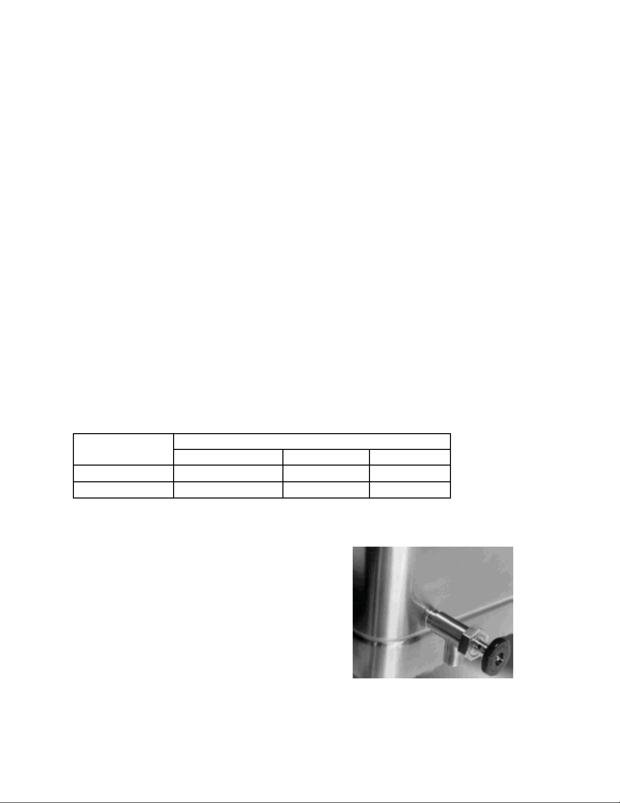
5. Draw-O Valve (can not be
eld installed)
9. Strainer for 2" TDO
valve
Optional Tangent Draw-Off
OM-BMP-E
OM/SM-BPM-E CE 5
Page 6
Inspection & Unpacking
The unit will arrive completely assembled,
wrapped inprotective plastic on a heavy skid, in a
heavycardboardcarton. Immediately upon receipt,
inspect the carton for damage. Report any
apparent shipping damage or an incorrect
shipment to the delivery agent.
When installation is to begin, get someone to
assist in removing the carton. Lift it straight up
and away from the unit. Do not simply raise it
and push backwards - it will break the cover
assembly vent handle. Write down the model
number, serial number, and installation date of
your unit, and keep this information for future
reference. Space for these entries is provided at
the top of the Service Log in this manual. Cut the
straps holding the unit on the skid, and lift the unit
straight up o the skid.
CAUTION
SHIPPING STRAPS ARE UNDER TENSION
AND CAN SNAP BACK WHEN CUT.
UNIT WEIGHS 420 TO 560 LB (190 TO 255
KG). FOR SAFE HANDLING, INSTALLER
SHOULD OBTAIN HELP AS NEEDED, OR
EMPLOY APPROPRIATE MATERIALS
HANDLING EQUIPMENT (SUCH AS A
FORKLIFT, DOLLY, OR PALLET JACK) TO
REMOVE THE UNIT FROM THE SKID AND
MOVE IT TO THEPLACE OF INSTALLATION.
The unit is strapped to a skid and shipped in a heavy cardboard carton.
(Shown is model BPM-30E)
6 OM/SM-BPM-E CE
Page 7
Single Phase
1. Installation
WARNING
THE BRAISING PAN MUST BE INSTALLED BY
PERSONNEL WHO ARE QUALIFIED TO WORK
WITH ELECTRICITY. IMPROPER INSTALLATION
COULD RESULT IN PERSONAL INJURY OR
EQUIPMENT DAMAGE.
Internal wiring for the Braising Pan is supplied complete.
When you receive the unit, it is ready for connection. A
wiring schematic is located inside the control box on the
right side of the pan, and in this manual.
Your pan was performance tested at the factory to
conrm that all controls and heating elements were
functioning correctly.
IMPORTANT
These appliances must be installed by a competent
person in conformity with the installation and servicing
instructions and national regulations in force at the
time. Particularattention must be paid to the following:
I.E.E. Regulations and Electrical Installations
Electricity at Work Regulations
Health and Safety at Work Act
Fire Precautions Act
Local and National Building Regulations
1.1 Installation is as follows:
Provide the proper electrical supply as
specied on the electrical information plate.
Comply with local codes and the National
Electrical Code ANSI/NFPA 70 - latest
edition.
Use appropriate sized copper wire,
rated at least 90ºC (194ºF).
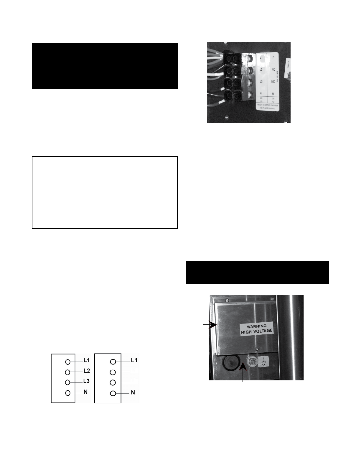
Units are wired at the factory for three
phase or single phase (per order) operation
and should be connected as shown
(See Fig. 1):
TERMINAL BLOCK
Set the unit in place and level it by turning the
adjustable feet. Crank the pan body to a
completely horizontal position. Check
levelness by placing a spirit level on the
bottom of the pan. The unit must be level to
avoid uneven cooking across the pan.
Make a water tight connection with the
incoming power line at the electrical service
entrance at the back of the control box. A BX
connection is NOT recommended. ELECTRICALLY
GROUND THE UNIT at the proper terminal.
WARNING
ELECTRICALLY GROUND THE BRAISING PAN
AT THE TERMINAL PROVIDED.
Three Phase
1.1.1
1.1.2
1.1.3
Fig. 1 Terminal Block
1.1.4
1.1.6
Conduit entry is at the control box on the rear left
side of the appliance. Access to the terminals is
gained by removing the terminal block cover
shown in gure 2.
1.1.5
Fig. 2
1.2. Water Supply - Not applicable to this appliance
except for optional faucets.
Terminal
Block
Cover
Conduit Entry Opening
OM/SM-BPM-E CE 7
Page 8
ELECTRICAL REQUIREMENTS
Model BPM-30E (CE) BPM-40E (CE)
WK1.41WK6.01tloV032
pmA61.1pmA64esahPelgniS
WK14.1WK10.6tloV004
pmA20.4pmA15.4esahPeerhT
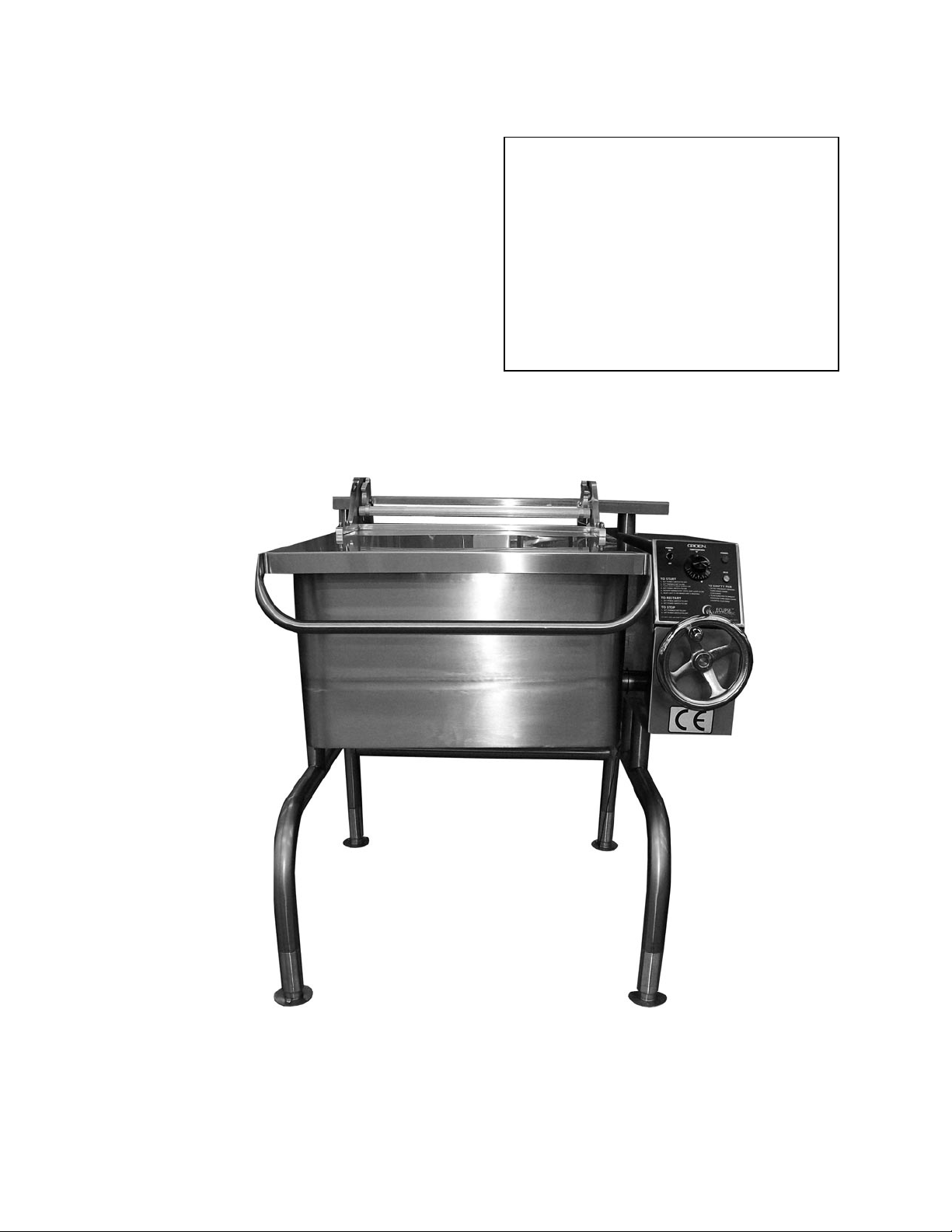
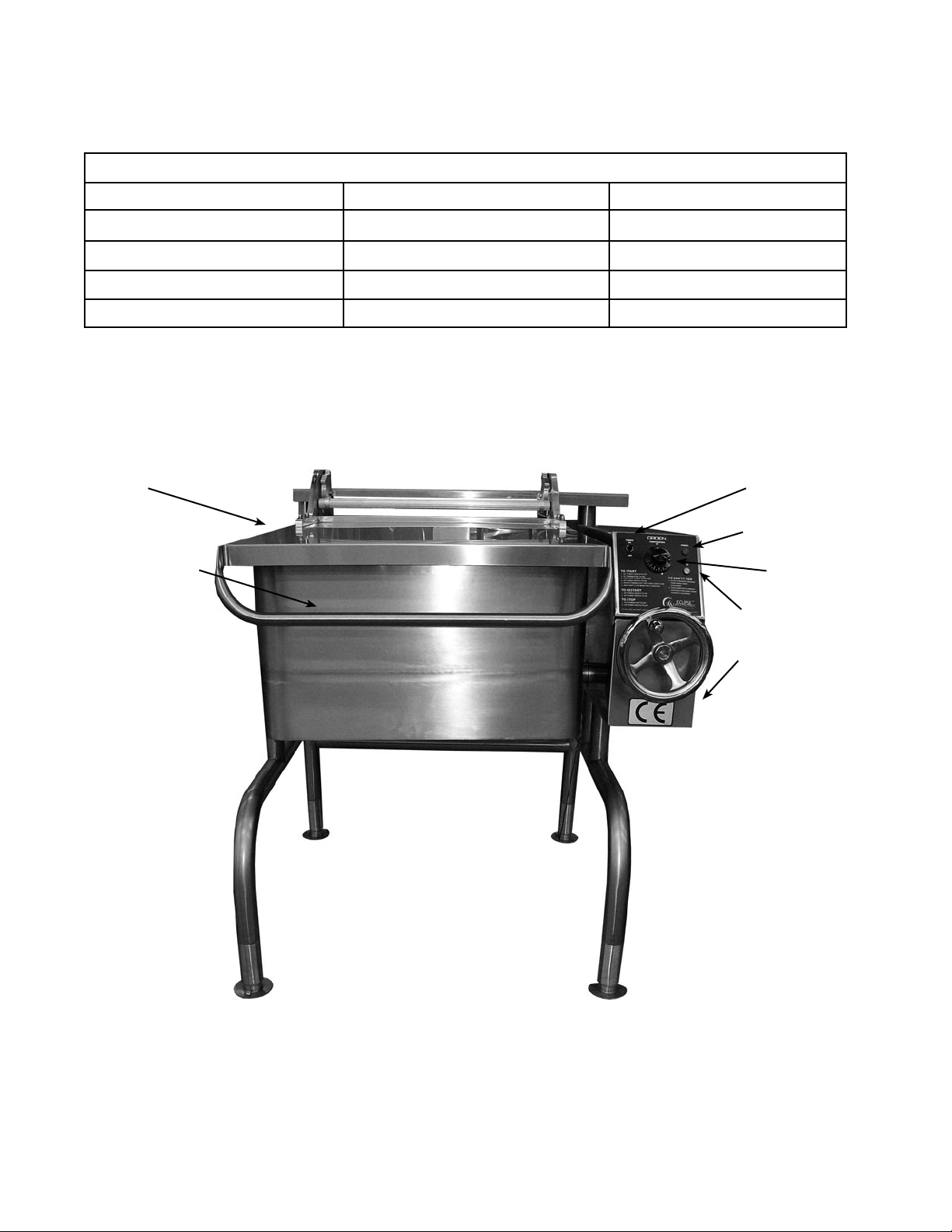
1.3 Electrical System Performance
Cover
Power Switch
Indicator Light
Cover Handle
Thermostat
Indicator Light
Stainless Steel
Console
8 OM/SM-BPM-E CE
Page 9
2. Assembly and Commissioning
2.1 Electrical Supply
Before commissioning the appliance, ensure that the
electrical installation has been performed in compliance
with relevant regulations. See Paragraph 1.1.
WARNING
THIS APPLIANCE MUST BE EARTHED.
2.2 Pre-Commissioning Check
a) Remove literature and packing materials from the
interior and exterior of the unit.
b) Put enough water into the pan to cover the bottom
to a depth of six to 12 mm. With the pan body in
the horizontal position, note how the water lies in
the pan, to conrm that the pan was leveled
properly during installation.
2.3 Operating the Braising Pan
2.3.1 Heating Sequence
a) Put water in the pan (6 to 12 mm deep).
b) Check that electricity main is “ON”.
c) Turn the toggle switch (Electrical Cabinet) to the
“ON” position. The red power neon will illuminate.
d) Turn the thermostat to the desired setting.
e) Observe that the elements are “ON” by the lighting
of the amber heat neon.
f) To switch “OFF” the unit, put the toggle switch in
the “OFF” position.
2.3.2 Checking Performance of Controls
a) Heat the unit as described in Paragraph 2.3.1,
above. Check that the amber heat neon is
glowing.
b) Turn the thermostat “OFF” and then “ON”. Check
that the amber heat light goes out when the
thermostat is turned o, and that it comes on when
it is switched back on. Repeat 2 - 3 times.
c) Remove all water from the pan and thoroughly dry
the pan.
d) Fill the pan with unused oil up to the mark in the
pan. Oil level must not exceed 50mm (2").
WARNING
DO NOT OVERFILL WITH OIL
OR FIRE MAY RESULT!
e) Set the thermostat knob at “10" and allow the oil to
heat up. Immerse a thermometer or thermocouple
25 mm below the oil surface at the center of the
pan. Check that the temperature stabilizes at
190ºC, (± 5ºC).
CAUTION
THE TEMPERATURE MUST NOT
EXCEED 200ºC
OR THE HIGH LIMIT THERMOSTAT WILL TRIP.
f) If the unit fails to operate as described, the unit
should be serviced by an Authorized Service
Representative.
2.4 Instructions to Installer
IMPORTANT: After installing and commissioning
the appliance, the User’s Instructions should be
handed to the user or purchaser. Ensure that the
instructions for heating, turning off, correct use
and cleaning are properly understood.
IMPORTANT
These appliances must be installed by a competent
person in conformity with the installation and servicing
instructions and national regulations in force at the
time. Particular attention must be paid to the following:
I.E.E. Regulations and Electrical Installations
Electricity at Work Regulations
Health and Safety at Work Act
Fire Precautions Act
Local and National Building Regulations
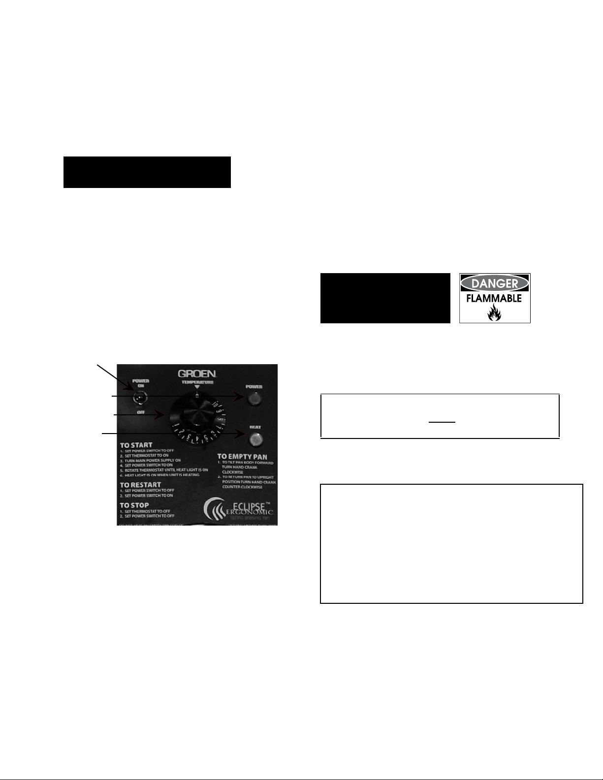
Power ON
Neon (Red)
Thermostat
Power ON/OFF
Switch
Heat ON
Neon
(Amber)
OM/SM-BPM-E CE 9
Page 10
3.1 Servicing
Note: When replacing wiring connections refer to
the wiring schematic in the unit or this
manual.
3.1.1 After Servicing
Check for correct operation as appropriate (see 2.3).
3.1.2 Regular Servicing Procedures
The gears must be checked at regular intervals.
The gear housing has been tted for proper
lubrication of moving parts. Since the gears do not
run in oil, periodic lubrication with grease is
essential. Frequency of lubrication depends on
operating conditions, but should occur at least once
every six months.
3. Service
WARNING
ELECTRICAL POWER MUST BE SHUT OFF
BEFORE WORK IS DONE ON INTERNAL
COMPONENTS
Groen recommends the use of a Number Two grade
LGI lithium grease. Add grease through the Zerk
ttings on the gear housing until grease ows out
of the bearings around the trunnion shaft. Place a
liberal amount of grease on the gear to cover the arc
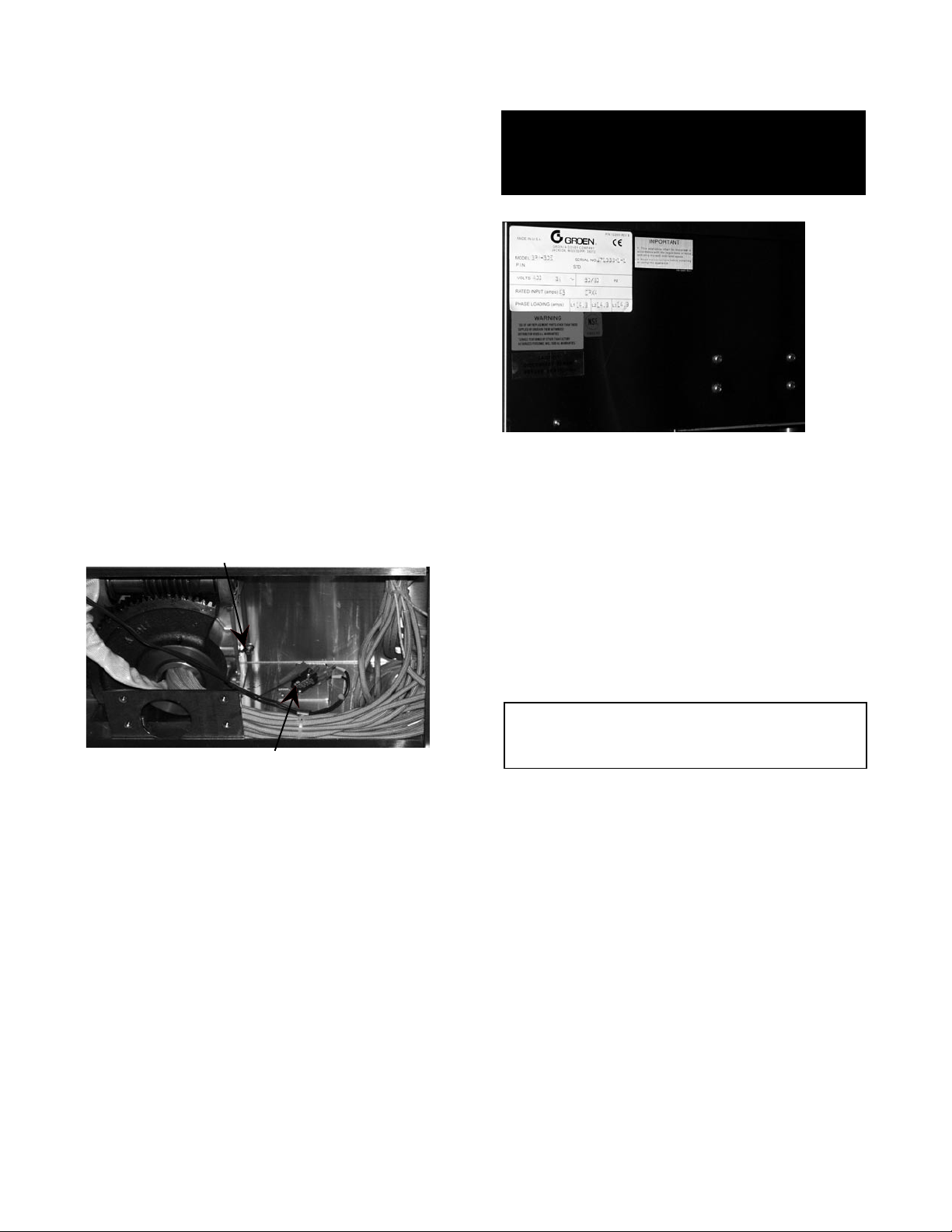
that is in contact with the worm gear (See Fig. 1).
Add grease through Zerk fitting
Fig. 1
Tilt switch & electrical insulating barrier
3.2 Removal of Control Panels
3.2.1 Removal of Electrical Cabinet Side Panel
a) Remove the two screws on lower edge of cover.
b) Remove the four screws at center of cover (See Fig. 2).
c) Remove the side panel.
d) Replace in reverse order.
3.2.2 Removal of Electrical Cabinet Top Panel Assy.
a) Remove the side panel (per 3.2.1 above).
b) Remove one screw on back side of the top panel
assembly.
c) Remove the two nuts holding the front edge of cover
to the gearbox after side panel is removed.
Fig. 2
3.3 Removal of Tilt Switch
(Turn electricity main off)
a) Remove the electrical cabinet side panel (See Fig. 1).
b) Disconnect electrical leads from tilt switch.
c) Remove the two screws holding the switch to the
bracket.
d) Remove tilt switch from control compartment.
e) Replace in reverse order. See CAUTION below.
CAUTION
BE SURE TO REPLACE THE ELECTRICAL
INSULATING BARRIER
3.4 Removal of On/Off Switch
(Turn electricity main off)
a) Remove the electrical cabinet top cabinet top panel
assembly and side panel as described in
Paragraph 3.2.2.
b) Disconnect electrical leads from On/O switch.
c) Undo and remove the retaining collar which
secures the On/O switch to the outer surface of
the electrical cabinet.
d) Withdraw the On/O switch from the control
compartment.
e) Replace in reverse order.
d) Replace in reverse order.
10 OM/SM-BPM-E CE
Page 11

3.5 Removal of Neons
(Turn electricity main off)
a) Remove electrical cabinet top panel assembly and
side panel as described in Paragraph 3.2.
b) Disconnect the electric leads from the neons.
c) Undo and remove the retaining collar which
secures the neon to the control cabinet.
d) Remove gasket between control box and neon.
e) Withdraw the neon from the control
compartment.
f) Replace in reverse order.
e) Remove four nuts which position the thermostat
bulb cover in place. (See Fig. 2)
f) Remove thermostat bulb cover.
g) Remove fasteners retaining the thermostat
capillary, bulb cover and insulated strip.
h) Remove water protection housing from thermostat shaft.
i) Thread thermostat bulb and capillary through the
trunnion.
j) Remove berglass sleeving from the thermostat
bulb and capillary.
k) Replace in reverse order.
3.6 Removal of Operating Thermostat
(Turn electricity main off)
3.6.1 To Replace
a) Remove electrical cabinet top panel assembly and
side panel as described in Paragraph 3.2.
b) Remove control knob from front panel.
c) Remove electrical leads from operating
thermostat.
3.6.2 To Calibrate
If calibration is required, use the following
procedures:
a) Fill the pan with unused oil to the indicated mark
(maximum oil level 50mm or less). Place a
thermocouple 25 mm below the oil surface in the
middle of the pan.
WARNING
DO NOT OVERFILL WITH OIL
OR FIRE MAY RESULT!
b) Remove the control knob and place a
screwdriver down the centre of the spindle.
c) Turn on the unit and allow the oil to heat.
d) Adjust the thermostat by turning the screwdriver
clockwise to decrease, and anti-clockwise to
increase temperature. Ensure that the
temperature settles at 190ºC (±5ºC). (Note:
Thermostat may cycle two to three times
before oil temperature settles at 190ºC).
e) Replace control knob.
Fig. 1
d) Remove cover from bottom of the pan by
removing four nuts. (See Fig. 1)
Fig. 2
3.7 Removal of High Limit Thermostat
(Turn electricity main off)
This device is set to open the contactor, to prevent
oil temperature from exceeding 230ºC. Manual
intervention is required to reset the control in the
event of a lockout.
OM/SM-BPM-E CE 11
Page 12

3.7.1 To Reset
3.7.3 Check Operation
a) Remove electrical cabinet top panel assembly and side
panel as described in Paragraph 3.2.
b) Push the reset button located on the high limit
thermostat. (See Fig. 3)
Fig. 3
3.7.2 To Replace
a) Remove electrical cabinet top panel assembly and side
panel as described in Paragraph 3.2.
b) Remove the two screws which secure the
high limit thermostat to mounting bracket. (See Fig. 3)
Operation of the high limit thermostat must be
checked regularly. Use the following procedure:
a) Remove the electrical cabinet top panel assembly and
side panel as described in Paragraph 3.2.
b) Fill the pan with unused oil to the indicated mark
(50mm maximum). Place a thermocouple or
thermometer 25 mm below the oil surface in the
middle of the pan.
WARNING
DO NOT OVERFILL WITH OIL OR
FIRE MAY RESULT!
c) Ensure that the electrical power is o before
continuing. Bypass the operating thermostat by
placing a jumper across the terminals. This
eectively removes the operating thermostat
from the circuit.
d) Switch the unit back on and heat the unit as
described in the heating instructions, above.
The elements will heat up the pan.
c) Remove electrical leads from high limit
thermostat.
d) Remove cover from bottom of the pan by
removing four nuts. (See Fig. 1 on previous page)
e) Remove four nuts which position the thermostat
bulb cover in place. (See Fig. 2 on previous page)
f) Remove thermostat bulb cover.
g) Remove fasteners retaining the thermostat
capillary, bulb cover and insulation strip.
h) Thread thermostat bulb and capillary through the
trunnion.
i) Remove berglass sleeving from the thermostat
bulb and capillary.
j) Replace in reverse order.
CAUTION
DO NOT LEAVE THE APPLIANCE DURING THIS
TEST.
e) If the high limit thermostat is functioning
correctly, the elements will cut o as the
temperature reaches 205 to 230ºC. Once the
high limit thermostat has tripped, switch o the
mains electricity. Remove the jumper from the
operating thermostat and replace all panels.
f) If the high limit thermostat switches, but not at
the specied temperature, the thermostat
requires replacement. Rejected thermostats
must be logged and returned.
g) To remove, see replacement procedures above.
NOTE: After this test, remove the jumper from
the operating thermostat.
h) Replace covers removed in step “a.”
12 OM/SM-BPM-E CE
Page 13

3.7.4 Calibration
The high limit thermostat is of the xed type. Its
calibration point may not be adjusted.
WARNING
IF THE HIGH LIMIT THERMOSTAT FAILS TO CUT
OFF AT 230ºC IMMEDIATELY TURN OFF THE
POWER. CONDUCT AN INVESTIGATION TO
DETERMINE THE FAULT, AND CORRECT IT
BEFORE USING THE APPLIANCE AGAIN.
3.8 Removal of Contactor
(Turn electricity main off)
a) Remove electrical cabinet top panel assembly and
side panel as described in Paragraph 3.2.
b) Loosen the screws on terminal to allow removal
of the wires.
c) Disconnect electrical leads from the contactor.
d) Remove the screws at the base of the contactor.
e) Remove contactor.
f) Replace in reverse order.
3.9 Removal of Transformer
a) Remove electrical cabinet lid and side panel, as
described in Paragraph 3.2 above.
c) Disconnect electrical connections.
b) Remove protective cover over the terminals.
d) Remove screws at the base of the transformer.
e) Remove transformer.
f) Replace in reverse order.
3.10 Fuse Replacement
a) Remove electrical cabinet top panel assembly and
3.11 Removal of Heating Element(s)
a) Identify the heating element that needs replacing
by checking its continuity and resistance. Specied
resistance of a new heating element should be
between 43 and 47.5 Ω (Ohm’s).
b) Remove electrical cabinet top panel cover
assembly as described in Paragraph 3.2.
c) Disconnect leads of the heater(s) to be
replaced from the contactors.
d) Remove cover from bottom of the braising pan
by removing four nuts. (see page 11 & Fig. 1).
e) Remove appropriate clamping nuts and
cast iron clamps.
f) Remove defective heaters.
g) Thread heater wires through the high
temperature sleeve and the trunion to remove
the heater.
h) Install new heater elements and tighten the
nuts to 13 (± 0.6) newton-meters.
i) Route heater wires through the sleeve and
trunion to the contactor and connect per
wiring schematic.
side panel as described in Paragraph 3.2.
b) Remove fuse from fuse holder.
c) Replace fuse with an identical fuse.
d) Replace in reverse order.
Transformer
Fuse
Contactor
OM/SM-BPM-E CE 13
Page 14

WIRING SCHEMATICS
Model BPM-30E CE
14 OM/SM-BPM-E CE
Page 15

WIRING SCHEMATICS
Model BPM-40E CE
OM/SM-BPM-E CE 15
Page 16

4. User Instructions
4.1 Heating and Operation
a) Check that the electricity main is “ON”.
b) Turn the toggle switch (Electrical Cabinet) to the
“ON” position. The red power neon will
illuminate.
c) Turn the operating thermostat (Electrical
Cabinet) to the desired setting.
d) Observe that the amber heat neon is “ON”.
4.2 To Shut Down Braising Pan
a) Turn thermostat dial to the “OFF” position.
b) Switch the On/O switch to the “OFF” position.
c) Turn the tilting handle clockwise to pour out the
water or contents.
4.3 Filling the Braising Pan
Using hot water and detergent, clean out the pan
thoroughly prior to operation.
The pan should not be overfilled, and an allowance
should always be made for expansion and foaming
of the food being cooked.
Do not use this Braising Pan for deep fat frying.
The depth of oil in the pan must never exceed
the maximum oil level mark on the inner pan
wall (50mm).
WARNING
DO NOT OVERFILL WITH
OIL OR FIRE MAY RESULT.
c) Safety Features:
• A high limit safety thermostat, which cuts off
power to the heating elements if the
operating thermostat fails (i.e., should the
temperature exceed operating limits).
• A tilt switch which automatically cuts off
power to the heating elements when the unit
is in a tilted position.
d) When the pan reaches the selected temperature,
the operating thermostat switch opens. This cuts
power to the heating elements and turns off the
amber heat neon.
e) When the pan cools below the selected
temperature, the operating thermostat switch
again closes and begins another heating cycle.
This On-Off cycle continues, maintaining the pan
at the desired temperature.
4.6 To Empty the Pan
Turn the hand crank on the front of the gear carrier
cabinet clockwise to tilt the pan body forward. The
pan will stay in position when you stop turning the
handle. To return it to the upright position, turn the
crank anti-clockwise.
WARNING
DO NOT STAND IN FRONT OF THE PAN WHEN
TILTING IT. BE CAREFUL TO KEEP HOT
CONTENTS FROM SPILLING. KEEP PEOPLE
AWAY FROM FRONT OF UNIT WHEN EMPTYING
THE PAN.
4.4 Thermostat
Provides automatic control of the braising pan
temperature at selected temperatures up to a
maximum of 190ºC.
4.5 Sequence of Operation
The following “sequence of operation” is provided to
help the user understand how the unit functions.
a) Switching the On/Off switch to the “ON” position
to start the appliance causes the red power neon
to illuminate.
b) Turning the operating thermostat sends a signal
to the contactor to close the circuit and allow the
heating elements to begin heating. This also
causes the amber heat neon to come on.
16 OM/SM-BPM-E CE
WARNING
WHEN TILTING PAN BODY FOR PRODUCT
TRANSFER:
1) WEAR PROTECTIVE OVEN MITT AND
PROTECTIVE APRON
2) USE DEEP CONTAINER TO CONTAIN
AND MINIMIZE PRODUCT SPLASHING.
3) PLACE CONTAINER ON STABLE, FLAT
SURFACE, AS CLOSE TO BRAISING PAN AS
POSSIBLE.
4) STAND TO LEFT OR RIGHT OF PAN
BODY WHILE POURING - NOT DIRECTLY IN
POUR PATH OF HOT CONTENTS.
5) POUR SLOWLY, MAINTAIN CONTROL OF
PAN BODY HANDLE AT ALL TIMES, AND
RETURN PANBODY TO UPRIGHT POSITION
AFTER CONTAINER IS FILLED OR
TRANSFER IS COMPLETE.
6) DO NOT OVERFILL CONTAINER. AVOID
DIRECT SKIN CONTACT WITH HOT
CONTAINER AND ITS CONTENTS.
.1
Page 17

CAUTION
DO NOT OVERFILL THE BRAISING PAN
WHEN COOKING, HOLDING OR
CLEANING. KEEP LIQUIDS AT LEAST 2-3”
(5-8 cm) BELOW THE PAN BODY RIM TO
ALLOW CLEARANCE FOR STIRRING,
BOILING PRODUCT AND SAFE
TRANSFER.
CAUTION
KEEP FLOORS IN FRONT OF THE KETTLE
WORK AREA CLEAN AND DRY. IF SPILLS
OCCUR, CLEAN AT ONCE TO AVOID SLIPS
OR FALLS.
4.8 Cooking Hints
a) To simmer or slowly heat an item, set the dial
at about 65
o
C (mark 6 on thermostat knob) or
lower. Put the cover down to keep moisture loss
at a minimum, or leave it up to help dry orreduce
the product. Set the thermostathigher tocook or
drive moisture o faster. The thermostat may be
adjusted to any setting in its range to cook exactly
as you wish.
b) Leave the cover open to allow excess steam
to escape. For longer simmering, you may
wish to close the cover toretain moisture.
WARNING
AVOID ANY EXPOSURE TO THE STEAM
ESCAPING FROM THE COVER VENT.
DIRECT CONTACT COULD RESULT IN
SEVERE BURNS
c) Standing at one side of the pan to avoid the
steam that will be released, grasp the
nearest corner of the cover handle and raise
the cover. The cover will stay in the open
position until you put it down.
d) To pour or dump product, remove grease, or
assist cleaning, first raise the cover, then tilt the
pan up and forward by turning the handwheel
clockwise. Whenever you stop turningthe wheel,
the pan body will hold its position (see warning
on page 16).
4.7 Power Failure
a) If power to the unit is lost, do not attempt to
operate the appliance until the electricity has
been restored.
b) When the power comes on again, follow the
steps in Paragraph 4.1, Heating and Operation.
WARNING
AVOID ALL DIRECT CONTACT WITH HOT
EQUIPMENT SURFACES. DIRECT SKIN
CONTACT COULD RESULT IN SEVERE
BURNS.
AVOID ALL DIRECT CONTACT WITH HOT
FOOD OR WATER IN THE BRAISING PAN.
DIRECT CONTACT COULD RESULT IN
SEVERE BURNS.
WARNING
IF THE PAN CONTAINS ITEMS IN SAUCE
OR MELTED FAT, THEY COULD SLIDE
FORWARD SUDDENLY DURING TILTING
AND CAUSE THE HOT LIQUID TO SPLASH
OUT.
e) To return the pan to the horizontal position,
turn the wheel counter-clockwise.
f) To turn the pan off, turn the thermostat to the
“OFF” position.
4.9 Routine Clean Up
After each use, turn the thermostat to “OFF” and
clean all food contact surfaces to ensure proper
sanitation. At the end of the day, or at least once
every 24 hours, turn off the heat and shut off
electric power to the unit and clean both the
interior and exterior of the pan. See Cleaning
Instructions for further detail.
OM/SM-BPM-E CE 17
Page 18

12
Use a brush, sponge, cloth, plastic or
rubber scraper, or plastic wool to clean.
Don’t use metal implements or steel wool
when cleaning.
5. Cleaning
1. Suggested Tools
a. A good stainless steel cleaner
b. Brushes in good condition
c. Cloth for cleaning controls
d. Chlorine sanitizer
e. Heavy Duty Cleaner (if required)
2. Procedure
WARNING
BEFORE ANY CLEANING OPERATION,
TURN THERMOSTAT DIAL TO “OFF” TO
CUT ANY POWER TO THE HEATING
ELEMENTS. BEFORE CLEANING ANY PART
OTHER THAN THE INSIDE OF THE PAN,
DISCONNECT ELECTRICAL SUPPLY AT
CIRCUIT BREAKER OR FUSE BOX.
a) Clean all food-contact surfaces soon
after use. It is best to clean the pan
before it has completely cooled. If the
unit is in continuous use, completely
clean and sanitize both the inside and
outside at least once every 12 hours.
CAUTION
KEEP WATER AND CLEANING SOLUTIONS
OUT OF CONTROLS AND ELECTRICAL
EQUIPMENT. DO NOT SPRAY OR HOSE
THE CONT R O L B O X OR OT H E R
ELECTRICAL CONNECTIONS. THEY ARE
NOT WATER-PROOF.
b) To remove any large amount of food left
in the pan, tilt the pan all the way up and
flush it with lukewarm water. Do not
damage the surface of the pan by
scraping it with a metal tool. Scratches
make the surface more difficult to clean,
and provide ideal breeding places for
bacteria.
CAUTION
MOST CLEANERS ARE HARMFUL TO THE
SKIN, EYES, MUCOUS MEMBRANES, AND
CLOTHING. PRECAUTIONS SHOULD BE
TAKEN. WEAR RUBBER GLOVES,
GOGGLES OR FACE SHIELD AND
PROTECTIVE CLOTHING. READ THE
WARNINGS AND CAREFULLYFOLLOW THE
DIRECTIONS ON THE CLEANER LABEL.
c) Following the supplier’s directions, make
up a warm solution of the cleaner.
Carefully wash the inside and outside of
the pan body with the cleaning solution.
d) Use a cloth moistened with cleaning
solution to clean controls, the control
console, and electric conduit.
18 OM/SM-BPM-E CE
Page 19

OM-BPM-E
e) Rinse the pan very well with lukewarm water,
and drain it completely.
f) As part of the daily cleaning program, clean
all inside and outside surfaces that may
have been soiled. Remember to check such
parts as the undersides of the cover, the
electrical console and other more remote
spots. Clean between the pan body and the
consoles using the brush provided (P/N
058705).
g) Controls and the control console may be
cleaned with a damp cloth or sprayed with a
garden hose spray connected to city water
supply. Do not use a pressure sprayer
directly on the unit or electrical parts.
h) To remove materials stuck to the equipment,
use a brush, sponge, cloth, plastic or rubber
scraper, or plastic wool with the cleaning
solution. To make washing easier, let the
cleaning solution sit in the unit and soak into
the residue, or heat the solution briefly. Do
not use any gritty cleaner or metal tool that
might scratch the surface. Scratches make
the surface harder to clean, and also provide
places for bacteria to grow. Do not use steel
wool. Small bit of steel wool left in the
surface of the unit can cause rusting and
pitting.
i) The outside of the unit may be polished with
a recognized stainless steel cleaner such as
Zepper from the Zep Manufacturing
Company.
j) When the equipment needs to be sanitized,
use a sanitizing solution equivalent to one
that supplies 100 parts per million available
chlorine. Get advice about the best
sanitizing agent from you supplier of
sanitizing products.
k) Following supplier instructions, apply the
sanitizing agent after the unit has been
cleaned and drained. Thoroughly drain o
the sanitizer.
CAUTION
NEVER LEAVE A CHLORINE SANITIZER IN
CONTACT WITH STAINLESS STEEL
SURFACES FOR LONGER THAN 30
MINUTES. LONGER CONTACT CAN CAUSE
CORROSION.
l) After the unit has been cleaned, sanitized and
drained, let all surfaces air dry unless the unit
must be used again right away.
m) It is recommended that the unit be sanitized
just before use. Follow the directions of the
sanitizer supplier.
n) About once a week (more often if the water is
very hard), use a heavy duty cleaner to
remove any mineral deposits or lm left by
hard water or foods. Follow the supplier’s
directions very carefully, and rinse the unit o
thoroughly, as soon as cleaning is nished.
CAUTION
KEEP CAUSTIC COMPOUNDS SUCH AS
FRYER BOILOUT CLEANERS AWAY FROM
ALUMINUM PARTS OF THE LID HINGE
SYSTEM AND THE COUNTERBALANCE
AS S EM B L Y . H I G H L Y C A U S T I C
COMPOUNDS COULD DAMAGE THIS
MATERIAL.
o) If especially dicult cleaning problems
persist, contact your cleaning product supplier
for help. The supplier has a trained technical
sta with laboratory facilities to serve you.
OM/SM-BPM-E CE 19
Page 20

6. Maintenance
Your Braising Pan is designed to require minimum
maintenance, but certain parts may need
replacement after prolonged use. After installation,
no user adjustment should be necessary. If a
service need arises, only authorized personnel
should perform the work.
WARNING
ELECTRIC POWER ALWAYS SHOULD BE
SHUT OFF BEFORE WORK IS DONE ON
INTERNAL COMPONENTS
Service personnel should check the unit at least
once a year. This periodic maintenance should
include inspecting wires and connections and
cleaning inside the control console. At least twice a
year grease the two trunnion bearings and worm
gear.
Groen recommends the use of number two grade
LGI lithium grease. Add grease through the zerk
fittings on the gear hosing until grease ows out of
the bearings around trunion shaft. Also, add grease
in the gear to cover arc that is in contact with the
worm gear. Clean up excess grease.
WARNING
DISCONNECT ELECTRICAL POWER
FROM THE UNIT BEFORE ATTEMPTING
TO GREASE THE TRUNNION SHAFT.
A Service Log is provided with the warranty
information at the back of this manual. Each time
service is performed on your Groen equipment, enter
the date on which the work was done, what was
done, and who did it. Keep the manual with the
equipment for quick and easy reference.
WARNING
ELECTRICAL POWER MUST BE SHUT OFF BEFORE WORK IS DONE ON INTERNAL COMPONENTS.
WARNING
USE OF ANY REPLACEMENT PARTS OTHER THAN THOSE SUPPLIED BY GROEN OR THEIR
AUTHORIZED DISTRIBUTORS CAN CAUSE INJURY TO THE OPERATOR AND DAMAGE TO THE
EQUIPMENT AND WILL VOID ALL WARRANTIES.
SERVICE PERFORMED BY OTHER THAN FACTORY-AUTHORIZED PERSONNEL WILL VOID ALL
WARRANTIES.
20 OM/SM-BPM-E CE
Page 21

SYMPTOM WHO WHAT TO CHECK
indicates items which must be performed by an authorized technician.
Pan will not heat, and
indicator light will not
light
User a. That power supply is on.
Auth Service
Rep Only
b. Fuses, accessible by removing electrical cabinet top
panel assembly.
Auth Service
Rep Only
c. For loose or broken wires.
d. Thermostat functioning, by listening for a click when
the switch opens or closes.
e. Contactor functioning.
Pan continues to heat
after it reaches
desired temperature
User a. Thermostat dial setting. Turn down if too high.
Auth Service
Rep Only
b. Thermostat functioning.
c. Thermostat calibration.
d. Contactor, to determine if it is de-energized.
X
X
X
X
X
X
X
Pan does not reach
desired temperature.
User a. Thermostat dial setting. Turn up if too low.
Auth Service
Rep Only
b. Heating elements for ground short or open (burned
out) element.
X
c. Thermostat functioning, by listening for a click when
the switch opens or closes.X
d. Thermostat calibration.X
e. Contactor functioning.X
Rapid clicking noise
(chattering)
User a. For low voltage.
Auth Service
Rep Only
b. Contactor for dirt or corrosion on the contacts.
c. Transformer step down voltage. X
X
Uneven cooking due
to “hot spots.”
User a. That the pan body is level
Uneven cooking due
to “cold spots.”
Auth Service
Rep Only
a. For open (burned out) heating element.
X
Pan is hard to tilt
(Manual Tilt Models)
User b.
Gears for foreign materials, lubrication and alignment.
WARNING
ELECTRICAL POWER MUST BE SHUT OFF BEFORE WORK IS DONE ON INTERNAL COMPONENTS.
WARNING
USE OF ANY REPLACEMENT PARTS OTHER THAN THOSE SUPPLIED BY GROEN OR THEIR
AUTHORIZED DISTRIBUTORS CAN CAUSE INJURY TO THE OPERATOR AND DAMAGE TO THE
EQUIPMENT AND WILL VOID ALL WARRANTIES.
SERVICE PERFORMED BY OTHER THAN FACTORY-AUTHORIZED PERSONNEL WILL VOID ALL
WARRANTIES.
7. Troubleshooting
Your Groen Braising Pan will operate smoothly and efficiently if properly maintained. However, the following is a
list of checks to make in the event of a problem. If the actions suggested do not solve the problem, call your
authorized Groen Service Representative. For the phone number of the nearest agency, call your area Groen
representative or the Groen Parts and Service Department. If an item on the list is followed by
only be performed by a qualified service representative.
X , the work should
Pan will not heat, but
indicator light comes
on.
Auth Service
Rep Only
a. Heating elements for short circuit.X
OM/SM-BPM-E CE 21
Page 22

STAND & FOOT ASSEMBLY
Key Part #
1 CASTER KIT (SET OF 2 WITH BRAKE AND 2 W/O BRAKE) 146354
1 CASTER WITH BRAKE (W/O FOOT ADAPTER) 146513
1 CASTER WITHOUT BRAKE (W/O FOOT ADAPTER)-NOT SHOWN 146515
2 FOOT ADAPTER 146516
3 FLANGED FOOT (W/O FOOT ADAPTER) 146521
4 BULLET FOOT (W/O FOOT ADAPTER) 146628
5 FRICTION RING 146520
PARTS LIST
Stand and Food Assembly
22 OM/SM-BPM-E CE
Page 23

Key Qty COVER & COUNTERBALANCE ASSEMBLIES Part #
1 1 COVER ASSEMBLY, 30 GALLON 160861
1 1 COVER ASSEMBLY, 40 GALLON 160808
145480
144790
2 1 COUNTERBALANCE ASSEMBLY, 30 GALLON
2 1 COUNTERBALANCE ASSEMBLY, 40 GALLON
3 4 STUD WELD, 1/4"-20 X 1-1/4" 012589
4 4 WASHER, LOCK 3/8" 005618
5 4 SCREW, HEX HEAD CAP 3/8"-16 X 1" 005612
6 4 NUT, HEX 3/8"-16 005619
7 4 DOME NUTS, 1/4-20 090567
8 2 SCREW, TRUSS HEAD, #10-32 X 3/8" 004173
PARTS LIST
Cover and Counterbalance Assemblies
OM/SM-BPM-E CE 23
Page 24

PARTS LIST
.ONTRAPNOITPIRCSEDYTQYEK
PAN & HEATING ELEMENTS
456541NOLLAG03,TNEMDLEWNAP11
987441NOLLAG04,TNEMDLEWNAP11
2 1 ELEMENT COVER WELD ASSY., 30 GALLON 146186
2 1 ELEMENT COVER WELD ASSY., 40 GALLON 144343
448210NOLLAG03,SPMALCRETAEH513
448210NOLLAG04,SPMALCRETAEH813
869210BLUBTATSOMREHTPMALC14
258210NOLLAG03,REGNAHTIUDNOC25
04921002-"4/1SPEKNOGAXEH,TUN4a6
6b 19 NUT, HEXAGON KEPS 5/16"-18, 30 GALLON 012941
6b 22 NUT, HEXAGON KEPS 5/16"-18, 40 GALLON 012941
6c 4 WASHER, FLAT
622540E (INSULATION)PATSSALGNEVOW.NI517
8 9 HEATER ELEMENTS, 30 GALLONS, 240V 153117
8 12 HEATER ELEMENTS, 40 GALLONS, 240V 153117
b
c
(30 Gallon Shown)
Pan and Element Cover Assembly
24 OM/SM-BPM-E CE
Page 25

PARTS LIST
153243
TRUNNION COVERS MANUAL TILT
.ONTRAPYTQYEK
467500DAEHSSURTWERCS62
3 1 RIGHT TRUNNION SIDE PANEL 145688
916500XEHTUN24
816500KCOLREHSAW25
516500PACDAEHXEHWERCS26
467421GNIRGNINIATER17
837731TEKCARBTECUAF18
9 8 SCREW, 1/4-20 x 3/8" TRUSS 125609
413441XOBKCOLBWOLLIP101
989200KCOLBWOLLIP111
377960DETTOLSXEH-WERCS231
14 1 TERMINAL BLOCK BOTTOM 146207
502641XOBKCOLBLANIMRET151
16 1 ELECTRICAL PANEL COVER ASSY. 153245
64 IN COVER GASKET (not shown) 145662
17 1 HOLE PLUG - 7/8”
18 1 HOLE PLUG - 1 1/4”
147309
147310
Trunnion Covers
OM/SM-BPM-E CE 25
Page 26

PARTS LIST
28 26
27 26
25
32 31 30 29
24
121313
14 10
5
15
19
19 20
18 22 22 23 23
7
7
8
1
16
5
5
234
20
10101010
10101010
10 10 10 10
21
21
6
17
119331010
Electrical Control Components
26 OM/SM-BPM-E CE
Page 27

PARTS LIST
NOTES:
1 ITEMS #33 THRU 37 NOT SHOWN
2 P/N 003122 IS TO BE TIGHTENED TO A TORQUE OF 4.5-4.7 IN-LBS
ITEM NO.
QTY.
PART NUMBER
DESCRIPTION
36
124in
152687
SLEEVE 3/4”, FIBERGLASS
35
6ft
003874
SLEEVING SIZE 7/16
34 1 153287
WIRING HARNESS POWER HIGH VOLTAGE BPM-40E
33 1 153286
WIRING HARNESS CONTROL LOW VOLTAGE BPM-40E
32 1 122000
KNOB, THERMOSTAT
31 1 107172
THERMOSTAT ADAPTER
30 1 123585
GASKET T-STAT
29 1 002180
THERMOSTAT, 200-400
28 1 116384
LIGHT, INDICATOR AMBER
27 1 116383
LIGHT, INDICATOR RED. 24V
26 2 137434
GASKET, LAMP
25 1 122004
POWER SWITCH
24 1 153245
ASSY, ELECTRICAL BOX COVER WELD BPM-30E (CE)
23 2 071297
NUT HEXAGON KEPS 4-40
22 2 003122
SCREW ROUND HEAD #4-40 X 3/4"
21 2 012940
NUT HEXAGON KEPS 1/4"-20
20 2 005610
SCREW HEX HD 1/4"-20 X 1"
19 2 146989
CLAMP, CABLE 3/8"
18 1 143319
SWITCH, TILT, DPST
17 1 003490
BARRIER, INSULATION
16 1 145689
WELDMENT, BRACKET, SPRING
15 1 122021
EQUIPOTENTIAL TERMINAL ASSY (CE UNITS)
14 1 119829
LUG, GROUND 14-6 AWG
13 2 005056
SCREW ROUND HEAD 8-32 1 1/4"
12 1 088214
TERMINAL BLOCK 4-POLE
11 1 153506
THERMOSTAT HI LIMIT BPM-E (CE)
10 15 069789
SCREW HEX SLOTTED HD W/WASHER #8-32 X 3/8"
9 1 153507
HI LIMIT THERMOSTAT BRACKET ASSY BPM-E (CE)
8 1 148899
TRANSFORMER, CE,208/230/460 TO 24V
7 2 148102
CONTACTOR, 3 POLE 30FLA
6
1.3ft
007937
EDGE TRIM
5 3 000453
BUSHING, SNAP 3/4 IN ID
4 1 077853
FUSE 3.0 AMP TYPE 3 AG
3 3 009697
SCREW PAN HEAD #6-32 X 3/8"
2 1 077854
FUSE HOLDER TYPE 3 AG
1 1 160804
ASSY, CONTROL PANEL BOX WELDMENT CE MARK BPM-30,40 G/E
37
1
128357
HARNESS ASSEMBLY, JUMPER (1 PHASE UNIT ONLY)
Electrical Control Components Continued
OM/SM-BPM-E CE 27
Page 28

PARTS LIST
MANUAL TILT ASSEMBLY
KEY QTY Part No.
1 1 GEAR CARRIER 002624
2 1 SHAFT, HANDWHEEL 144834
3 1 GEAR, WORM 128001
4 1 GEAR SECTOR 009829
5 1 KEY GIB 012031
6 1 HANDWHEEL 012061
7 2 PIN ROLL 012614
8 1 SCREW SET SOCKET 012060
9 2 BEARING ROLLER 002790
10 1 BEARING SLEEVE 137239
11 1 PLUG PIPE 010286
14 1 FITTING GREASE 90 (NOT SHOWN) 012195
15 1 BUSHING SNAP (NOT SHOWN) 000453
16 2 WASHER LOCK 005618
17 2 SCREW HEX HEAD CAP 005612
Manual Tilt Assembly
28 OM/SM-BPM-E CE
Page 29

10. Service Log
Model No. ___________________________ Purchased From _____________________
Serial No. ___________________________ Location ____________________________
Date Purchased ______________________ Date Installed ________________________
Purchase Order No. ___________________ For Service Call ______________________
Date Maintenance Performed Performed by
OM/SM-BPM-E CE 29
Page 30

10. Service Log
Model No. ___________________________ Purchased From _____________________
Serial No. ___________________________ Location ____________________________
Date Purchased ______________________ Date Installed ________________________
Purchase Order No. ___________________ For Service Call ______________________
Date Maintenance Performed Performed by
30 OM/SM-BPM-E CE
Page 31

Limited Warranty To Commercial Purchasers*
(for Areas Outside of the U.S. and Canada)
Groen Foodservice Equipment ("Groen Equipment") has been skillfully manufactured, carefully inspected and
packaged to meet rigid standards of excellence. Groen warrant their Equipment to be free from defects in
material and workmanship for (12) twelve months, with the following conditions and subject to the following
limitations.
I. This parts and labor warranty is limited to Groen Equipment sold to the original commercial purchaser/ users
(but not original equipment manufacturers), at its original place of installation, in areas outside the U.S. and
Canada.
II. Damage during shipment is to be reported to the carrier, and is not covered under this warranty, and is the sole
responsibility of the purchaser/user.
III. Groen, or an authorized service representative, will repair or replace, at Groen's sole election, any Groen
Equipment, including but not limited to, draw off valves, safety valves, gas and electric components, found to
be defective during the warranty period.
IV. This warranty does not cover boiler maintenance, calibration, or periodic adjustments as specified in
operating instructions or manuals, and consumable parts such as scraper blades, gaskets, packing, etc., or
labor costs incurred for removal of adjacent equipment or objects to gain access to Groen Equipment. This
warranty does not cover defects caused by improper installation, abuse, careless operation, or improper
maintenance of equipment. This warranty does not cover damage caused by poor water quality or improper
boiler maintenance.
V. THIS WARRANTY IS EXCLUSIVE AND IS IN LIEU OF ALL OTHER WARRANTIES, EXPRESSED OR
IMPLIED, INCLUDING ANY IMPLIED WARRANTY OF MERCHANTABILITY OR FITNESS FOR A
PARTICULAR PURPOSE, EACH OF WHICH IS HEREBY EXPRESSLY DISCLAIMED. THE REMEDIES
DESCRIBED ABOVE ARE EXCLUSIVE AND IN NO EVENT SHALL GROEN BE LIABLE FOR SPECIAL,
CONSEQUENTIAL OR INCIDENTAL DAMAGES FOR THE BREACH OR DELAY IN PERFORMANCE OF
THIS WARRANTY.
VI. Groen Equipment is for commercial use only. If sold as a component of another (O.E.M.) manufacturer's
equipment or if used as a consumer product, such Equipment is sold AS IS and without any warranty.
* (Covers All Food Service Equipment Ordered After October 1, 1995)
OM/SM-BPM-E CE 31
Page 32

1055 Mendell Davis Drive • Jackson MS 39272
888-994-7636 • 601-372-3903 • Fax 888-864-7636
groen.com
PART NUMBER 153352, REV. A (3/07)
 Loading...