

Page 1
IMPORTANT INFORMATION
IMPORTANT INFORMATION KEEP FOR OPERATOR
IMPORTANT INFORMATION IMPORTANT INFORMATION
KEEP FOR OPERATOR IMPORTANT INFORMATION
KEEP FOR OPERATOR KEEP FOR OPERATOR
IMPORTANT INFORMATION
IMPORTANT INFORMATION IMPORTANT INFORMATION
E-MPB-MO LAUNAM ROTAREPO
Part Number 145340 Rev A DOMESTIC
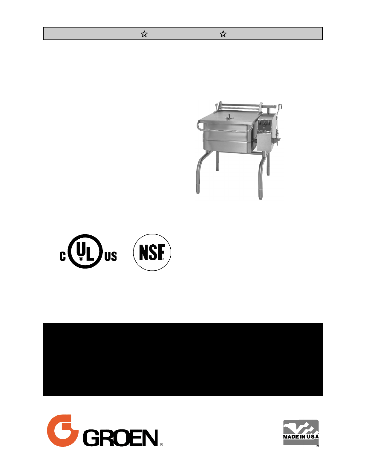
MODELS: BPM-30E, BPM-40E
BPP-30E, BPP-40E
Braising Pans
Eclipse™Ergonomic
Tilting Braising Pans
Stainless Steel
Manual or Power Tilt
Electrically Heated
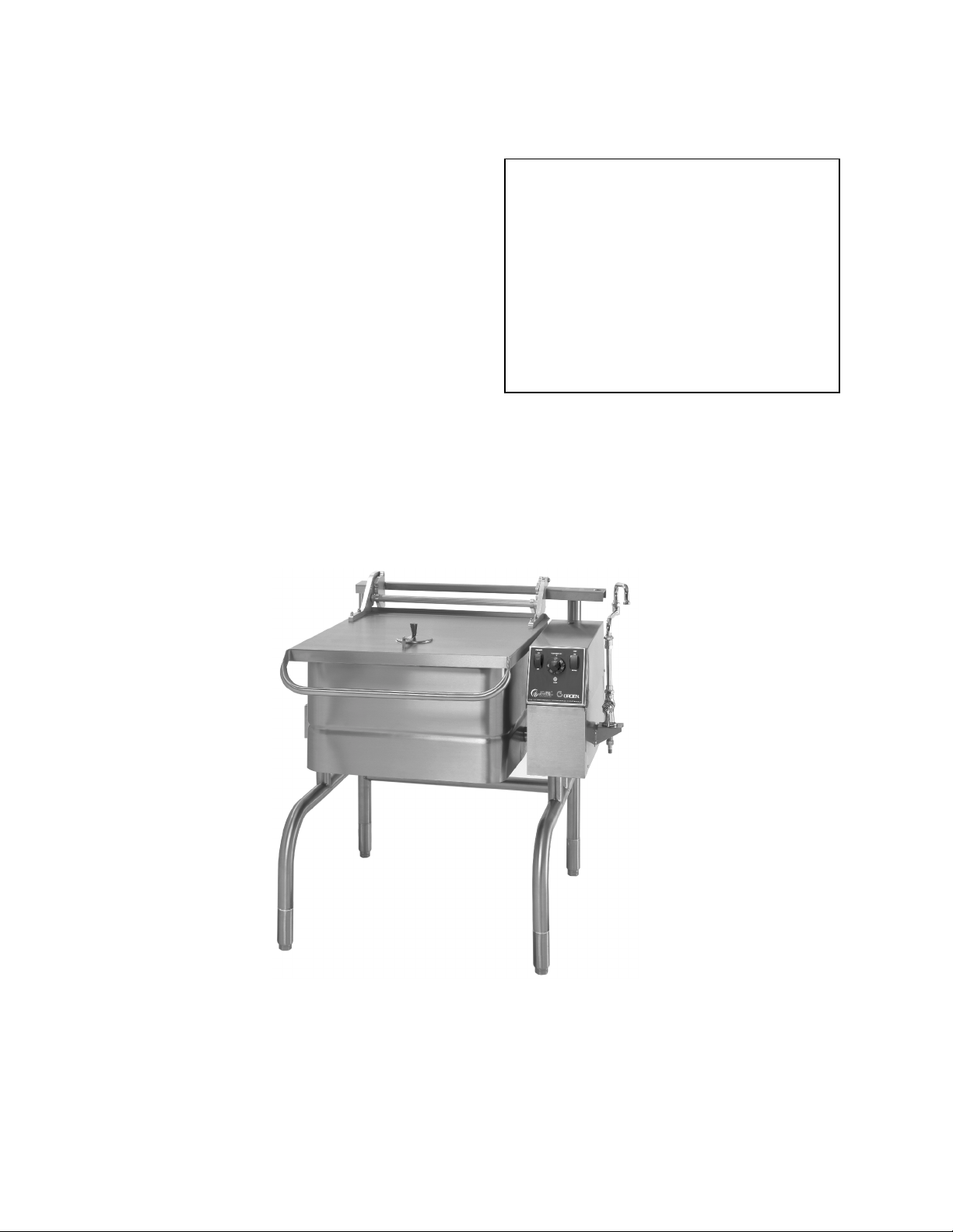
Model BPP-30E Shown
THIS MANUAL MUST BE RETAINED FOR FUTURE REFERENCE. READ,
UNDERSTAND AND FOLLOW THE INSTRUCTIONS AND WARNINGS
CONTAINED IN THIS MANUAL.
WARNING
DO NOT STORE OR USE GASOLINE OR OTHER FLAMMABLE VAPORS AND
LIQUIDS IN THE VICINITY OF THIS OR ANY OTHER APPLIANCE.
WARNING
IMPROPER INSTALLATION, ADJUSTMENT, ALTERATION, SERVICE OR
MAINTENANCE CAN CAUSE PROPERTY DAMAGE, INJURY OR DEATH. READ
THE INSTALLATION, OPERATING AND MAINTENANCE INSTRUCTIONS
THOROUGHLY BEFORE INSTALLING OR SERVICING THIS EQUIPMENT
.
Information contained in this document is
known to be current and accurate at the time
of printing/creation. Unified Brands recommends referencing our product line websites,
unifiedbrands.net, for the most updated
product information and specifications.
Page 2

OM-BPM-E
IMPORTANT — READ FIRST — IMPORTANT
CAUTION: BE SURE OPERATORS READ, UNDERSTAND AND FOLLOW THE OPERATING
INSTRUCTIONS, CAUTIONS, AND SAFETY INSTRUCTIONS IN THIS MANUAL.
WARNING: THIS UNIT IS INTENDED FOR USE IN THE COMMERCIAL HEATING, COOKING AND
HOLDING OF WATER AND FOOD PRODUCTS, PER THE INSTRUCTIONS
CONTAINED IN THIS MANUAL. ANY OTHER USE COULD RESULT IN SERIOUS
PERSONAL INJURY OR DAMAGE TO EQUIPMENT AND WILL VOID WARRANTY.
WARNING: ELECTRICALLY GROUND THE PAN AT THE TERMINAL PROVIDED. FAILURE TO
GROUND UNIT COULD RESULT IN ELECTROCUTION AND DEATH.
WARNING: THE BRAISING PAN MUST BE INSTALLED BY PERSONNEL WHO ARE QUALIFIED
TO WORK WITH ELECTRICITY. IMPROPER INSTALLATION COULD RESULT IN
PERSONAL INJURY OR EQUIPMENT DAMAGE.
CAUTION: STAND AWAY FROM HOT WATER OR FOOD PRODUCTS WHILE TILTING THE PAN
DIRECT CONTACT COULD RESULT IN SEVERE BURNS.
WARNING: WHEN TILTING BRAISING PAN FOR PRODUCT TRANSFER:
1) WEAR PROTECTIVE OVEN MITT AND PROTECTIVE APRON.
2) USE CONTAINER DEEP ENOUGH TO CONTAIN AND MINIMIZE SPLASHING.
3) PLACE CONTAINER ON STABLE, FLAT SURFACE, AS CLOSE TO PAN AS
POSSIBLE.
4) STAND TO SIDE OF PAN WHILE POURING — NOT DIRECTLY IN POUR PATH OF
HOT CONTENTS.
5) RETURN PAN BODY TO LEVEL POSITION AFTER CONTAINER IS FILLED OR
TRANSFER IS COMPLETE.
6) DO NOT OVER FILL CONTAINER. AVOID DIRECT SKIN CONTACT WITH HOT
CONTAINER AND ITS CONTENTS.
WARNING: DO NOT HEAT AN EMPTY PAN FOR MORE THAN FIVE MINUTES AT A SETTING
HIGHER THAN 300
WARNING: AVOID ANY EXPOSURE TO THE STEAM ESCAPING FROM THE COVER VENT.
DIRECT CONTACT COULD RESULT IN SEVERE BURNS
WARNING: AVOID ALL DIRECT CONTACT WITH HOT EQUIPMENT SURFACES. DIRECT SKIN
CONTACT COULD RESULT IN SEVERE BURNS.
WARNING: AVOID ALL DIRECT CONTACT WITH HOT FOOD OR WATER IN THE BRAISING
PAN. DIRECT CONTACT COULD RESULT IN SEVERE BURNS.
WARNING: IF THE PAN CONTAINS ITEMS IN SAUCE OR MELTED FAT, THEY COULD SLIDE
FORWARD SUDDENLY DURING TILTING AND CAUSE HOT LIQUID TO SPLASH
OUT.
WARNING: USE OF ANY REPLACEMENT PARTS OTHER THAN THOSE SUPPLIED BY GROEN
OR ITS AUTHORIZED DISTRIBUTORS VOIDS ALL WARRANTIES AND MAY CAUSE
BODILY INJURY OR EQUIPMENT DAMAGE. SERVICE PERFORMED BY OTHER
THAN FACTORY AUTHORIZED PERSONNEL WILL VOID ALL WARRANTIES.
WARNING: TURN OFF ELECTRIC POWER BEFORE WORKING ON INTERNAL COMPONENTS.
WARNING: BEFORE ANY CLEANING OPERATION, TURN THE THERMOSTAT TO “OFF” TO
CUT OFF POWER TO THE HEATING ELEMENTS. BEFORE CLEANING ANY PART
OTHER THAN THE INSIDE OF THE PAN, DISCONNECT THE ELECTRICAL SUPPLY
AT THE CIRCUIT BREAKER OR FUSE BOX.
WARNING: BE CAREFUL TO AVOID CONTACT WITH CLEANING PRODUCTS IN ACCORDANCE
WITH SUPPLIER AND MANUFACTURER RECOMMENDATIONS. MANY CLEANERS
ARE HARMFUL TO THE SKIN, EYES, MUCOUS MEMBRANES AND CLOTHING.
READ THE WARNINGS AND FOLLOW DIRECTIONS ON THE CLEANER LABEL.
o
F.
2
Page 3

OM-BPM-E
IMPORTANT — READ FIRST — IMPORTANT
CAUTION: NEVER LEAVE A CHLORINE SANITIZER IN CONTACT WITH STAINLESS STEEL
FOR LONGER THAN 30 MINUTES. LONGER CONTACT CAN CAUSE CORROSION.
WARNING: DO NOT USE ANY FUSE WITH A HIGHER AMP RATING THAN THE RATING SPECIFIED FOR
THAT CIRCUIT.
WARNING: KEEP WATER AND SOLUTIONS OUT OF CONTROLS AND ELECTRICAL
EQUIPMENT. NEVER USE A HIGH PRESSURE HOSE TO CLEAN THE BRAISING
PAN.
WARNING: BEFORE REPLACING ANY PARTS, DISCONNECT THE UNIT FROM THE ELECTRIC
POWER SUPPLY.
IMPORTANT: SERVICE PERFORMED BY OTHER THAN FACTORY AUTHORIZED PERSONNEL
WILL VOID WARRANTIES.
3
Page 4

OM-BPM-E
Table of Contents
IMPORTANT OPERATOR WARNINGS .................................................. 2
EQUIPMENT DESCRIPTION .......................................................... 5
INSPECTION & UNPACKING .......................................................... 6
INSTALLATION ..................................................................... 7
INITIAL START-UP .................................................................. 9
OPERATION ....................................................................... 9
SEQUENCE OF OPERATION ......................................................... 11
CLEANING ........................................................................ 12
MAINTENANCE .................................................................... 14
TROUBLESHOOTING ............................................................... 14
PARTS LISTS ..................................................................... 16
ELECTRICAL PARTS CHART......................................................... 26
REFERENCES..................................................................... 26
DIAGRAMS & SCHEMATICS ......................................................... 27
MAINTENANCE LOG................................................................ 33
WARRANTY....................................................................... 34
4
Page 5
OM-BPM-E
Equipment Description
The Groen BPM-E is a stainless steel, electrically
heated Braising Pan which is equipped with
integrated heating elements, a hand operated or
motor powered tilting mechanism, electrical
controls and a hinged cover. The Braising Pan
serves as a braising unit, griddle, fry pan, oven,
kettle, bain-marie, or food warmer and server. It
can also be adapted for use as a non-pressure
steamer.
The pan body is constructed of heavy-duty
stainless steel, welded into a solid piece. It has a
polished interior and exterior finish. A pouring lip
is welded to the top of the front wall. The cooking
surface is a stainless steel clad plate fitted with
clamped-on electrical heating elements. The
elements are positioned to ensure uniform heat
transfer over the entire surface.
Models BPM and BPP are mounted on an openleg frame which is fabricated from tubular stainless
steel. Models MW/BPM and MW/BPP are
designed to be wall-mounted with side support
arms and a back-splash. They do not have legs.
An easily operated worm and gear mechanism tilts
the pan body and provides precise control for
pouring or dumping its contents.
This tilting mechanism is located in a stainless
steel console to right of the pan body. For power
tilt units a three position switch on the front of the
control console gives the operator positive,
smooth-acting control of tilt. To facilitate cleaning,
the pan body can be tilted past the vertical
position.
Heating elements and other electrical components
are enclosed for safety. The thermostat, heating
indicator light and tilting switch are contained in a
compact control console which is mounted to the
right of the pan body.
The thermostat provides automatic control of
cooking temperature. Turning the thermostat dial
starts and stops heating and sets the pan
temperature. Only one electrical connection is
required to install the unit.
A vented, heavy gauge, one-piece, stainless steel
cover with a rear condensate drip shield on the
underside is standard on the Braising Pan. A fully
enclosed torsion bar-type counter-balance
provides easy operation to open the cover to
maintain it open at any position. The cover opens
to the back. It is hinged to the frame, so it moves
independently from the pan body.
MODELS
BPM-30E
BPP-30E
BPM-40E
BPP-40E
The following optional equipment may
be added to any floor model listed above:
1. Fill faucet - swing spout
single or double pantry
2. Fill faucet - 48" or 60" spray
hose assembly - single or
double pantry
3. Caster mounting kit
4. Flanged Feet Kit
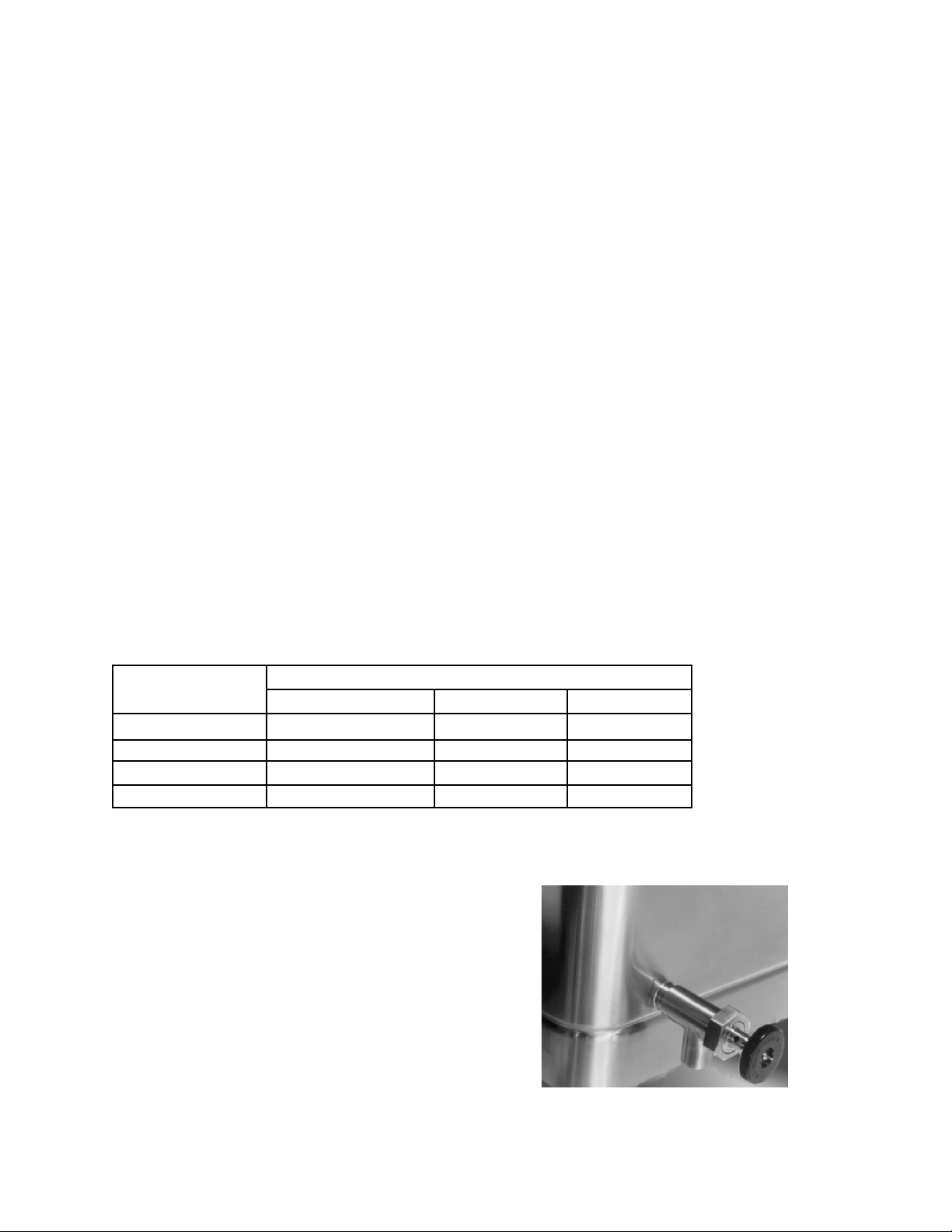
5. Draw-Off Valve (can not be
field installed)
Left to Right Front to Back Depth
26.25 28.25 10"
26.25 28.25 10"
35.75 35.75 10"
35.75 35.75 10"
6. Steamer insert set
7. Steamer pan carrier
8. Pouring Lip Strainer
9. Strainer for 2" TDO
valve
The following sizes and options are available:
Pan Dimensions (Inside)
Optional Tangent Draw-Off
5
Page 6
OM-BPM-E
Inspection and Unpacking
The unit will arrive completely assembled,
wrapped in protective plastic on a heavy skid, in a
heavy cardboard carton. Immediately upon receipt,
inspect the carton for damage. Report any
apparent shipping damage or an incorrect
shipment to the delivery agent.
When installation is to begin, get someone to
assist in removing the carton. Lift it straight up
and away from the unit. Do not simply raise it
and push backwards - it will break the cover
assembly vent handle. Write down the model
number, serial number, and installation date of
your unit, and keep this information for future
reference. Space for these entries is provided at
the top of the Service Log in this manual. Cut the
straps holding the unit on the skid, and lift the unit
straight up off the skid.
CAUTION
SHIPPING STRAPS ARE UNDER TENSION
AND CAN SNAP BACK WHEN CUT.
UNIT WEIGHS 420 TO 560 LB (190 TO 255
KG). FOR SAFE HANDLING, INSTALLER
SHOULD OBTAIN HELP AS NEEDED, OR
EMPLOY APPROPRIATE MATERIALS
HANDLING EQUIPMENT (SUCH AS A
FORKLIFT, DOLLY, OR PALLET JACK) TO
REMOVE THE UNIT FROM THE SKID AND
MOVE IT TO THE PLACE OF INSTALLATION.
The unit is strapped to a skid and shipped in a heavy cardboard carton.
(Shown is model BPP-40E with optional right side mounted double pantry faucet assembly.)
6
Page 7

OM-BPM-E
Installation
WARNING
INSTALLATION OF THE BRAISING PAN
MUST BE DONE BY A CERTIFIED
ELECTRICIAN OR GROEN AUTHORIZED
REPRESENTATIVE QUALIFIED TO WORK
WITH ELECTRICITY. IMPROPER
INSTALLATION CAN RESULT IN INJURY TO
PERSONNEL AN/OR DAMAGE TO
EQUIPMENT.
Internal wiring for the Braising Pan is supplied
complete. When you receive the unit, it is ready for
connection. A wiring diagram is located inside the
control box on the right side of the pan, as well as in
this manual (pp. 28-33).
Your pan was performance-tested at the factory to
confirm that all controls and heating elements were
functioning correctly.
Installation is as follows:
1. Set the unit in place and level it by turning the
adjustable feet. Crank the pan body to a
completely horizontal position. Check levelness
by placing a spirit level on the bottom of the pan.
The unit must be level to avoid uneven cooking
across the pan.
3. Provide the proper electrical supply as specified
on the electrical information plate. Comply with
local codes and the National Electrical Code
ANSI/NFPA 7- latest edition.
4. Use only copper wire, rated at least 75ºC and of
proper gage. See chart on page 8.
5. Standard equipment is shipped ready for 208V,
240V, or 480V, 3-phase operation. Refer to the
wiring diagram located on the inside cover of the
control box and the instructions below for
conversion to single-phase operation.
A jumper wire and “conversion” label are included
with the unit. They can be found in a plastic bag
attached to the trunnion assembly inside the
control box.
CAUTION
BEFORE ANY ELECTRICAL CONVERSION,
VERIFY THAT THE BRANCH CIRCUIT
WIRING IS ADEQUATE TO HANDLE ANY
INCREASE IN AMPERAGE REQUIREMENTS.
REFER TO THE ELECTRICAL
SPECIFICATIONS LISTED BELOW.
6. For conversion from 3-phase to 1-phase
2. Make a waterproof connection with the incoming
power line at the electrical service entrance at the
bottom of the connection box at rear of control
console. A BX connection is NOT recommended.
ELECTRICALLY GROUND THE UNIT at the
proper terminal.
i. Verify that the branch circuit wiring is adequate
for any increased amperage requirements. (See
table on next page)
ii. 1-phase requires two jumper wires. One
jumper wire exists on the terminal block for 3phase input. The second jumper wire is located in
a plastic bag inside the control box.
iii. Attach jumper wires to terminal block as per
wiring diagram for 1 phase supply.
iv. Complete “conversion label” (supplied in bag)
and adhere it to the control box near the UL
dataplate.
7
Page 8
OM-BPM-E
Electrical Requirements
Note: Use only copper wire rated for 75°c or higher
Model Power 208 V, 1 Phase 240 V, 1 Phase 208 V, 3 Phase 240 V, 3 Phase 400 V, 3 Ph, 4 Wire 480 V, 3 Phase
BPM-30E
BPP-30E
BPM-40E
BPP-40E
Amps Supply
Wire
11.5 kw 56 #6 AWG 48 #6 AWG 32 #8 AWG 28 #10 AWG 17 #14 AWG 14 #14 AWG
11.5 kw 56 #6 AWG 48 #6 AWG 32 #8 AWG 28 #10 AWG 17 #14 AWG 14 #14 AWG
15.3 kw 74 #4 AWG 64 #4 AWG 43 #8 AWG 37 #8 AWG 22.5 #12 AWG 19 #14 AWG
15.3 kw 74 #4 AWG 64 #4 AWG 43 #8 AWG 37 #8 AWG 22.5 #12 AWG 19 #14 AWG
Amps Supply
Wire
Amps Supply
Wire
Amps Supply
Wire
Amps Supply
Wire
Amps Supply
Wire
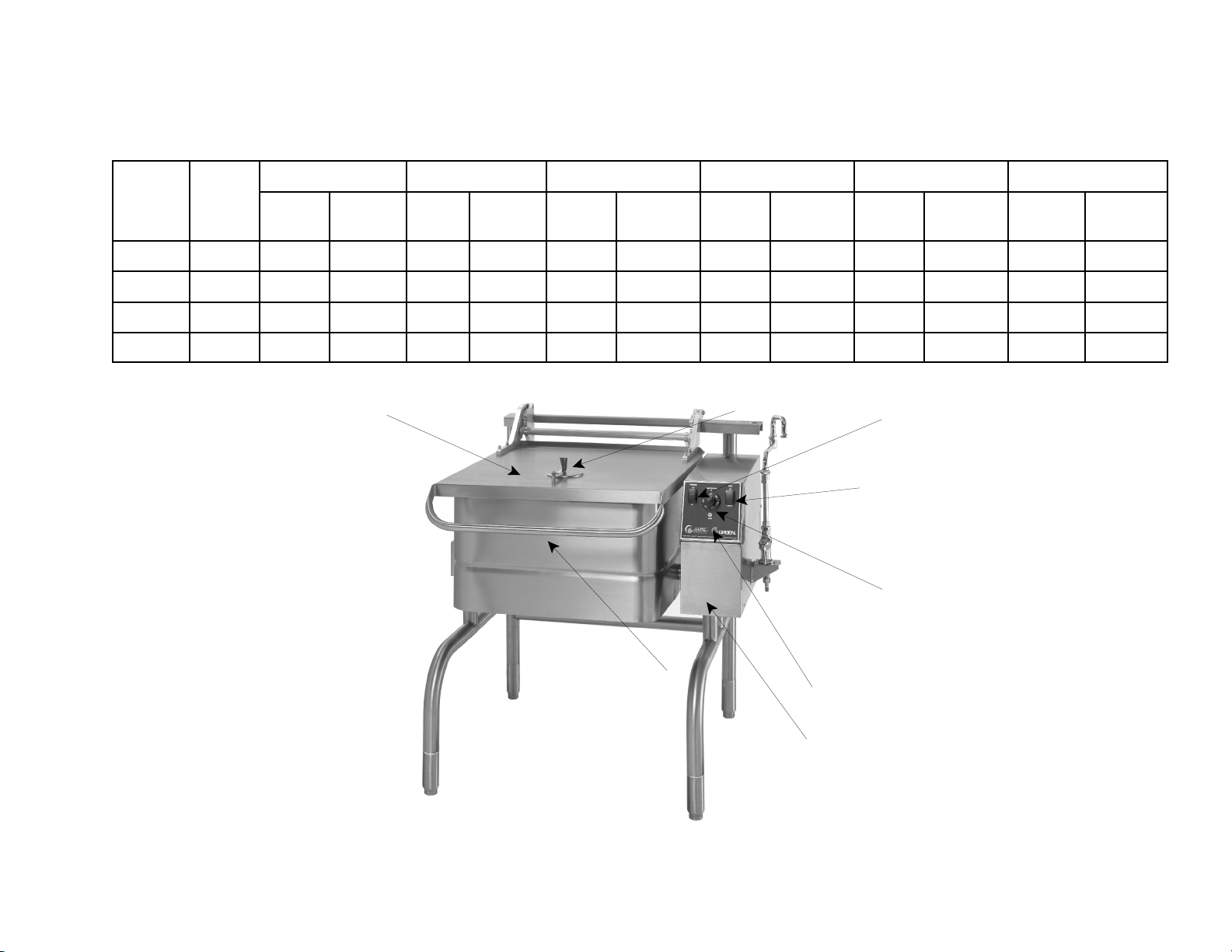
Vent
Cover
Power
Switch
Tilt
Switch
Thermostat
Cover Handle
Model BPP-30E Shown (with optional faucet)
8
Indicator
Light
Stainless Steel
Console
Page 9

OM-BPM-E
Initial Start-Up
5. To shut the unit down, turn the thermostat dial to “OFF.”
Now that the Braising Pan has been installed, you should
test it to ensure that the unit is operating correctly.
1. Remove all literature and packing materials from the
interior and exterior of the unit.
2. Turn on the electrical power to the unit.
3. Put enough water into the pan to cover its bottom to a
depth of ¼” to ½” (6 to 13 mm). With the pan body in
the horizontal position, note how the water covers the
pan bottom. This is a good method to use for
confirming that the unit is properly leveled.
4. Set the thermostat to 235
light should come on to show that the pan is heating.
Heating should continue until the water boils.
o
F. The heating indicator
WATER IS EXTREMELY HOT AND CAN CAUSE
SEVERE BURNS. AVOID CONTACT WITH HOT
WATER WHEN EMPTYING UNIT.
6. Turn the tilting handwheel clockwise to pour out the
water and to confirm that the pan body can be tilted
smoothly from horizontal to vertical. For BPP models,
push the UP/DOWN switch to confirm operation of
tilting system.
If the unit functions as described above, it is ready for use.
If it does not, contact your local Groen Authorized Service
Agency.
WARNING
Operation
IMPORTANT:
BE SURE ALL OPERATORS READ, UNDERSTAND AND FOLLOW THE OPERATING INSTRUCTIONS,
CAUTIONS, AND SAFETY INSTRUCTIONS CONTAINED IN THIS MANUAL.
A. Controls
Operator controls for the Braising Pans are:
1. Power ON Switch and Power ON indicator
located on the control console.
2. The thermostat dial, located on the control
console to the right of the pan body. This dial is
used to turn the thermostat on or off and to set
the thermostat for pan temperatures between
175° and 400°.
3. Heating indicator light located on the control
console, lights when the burners have ignited.
4. A handwheel controls the worm and gear
mechanism that smoothly tilts the pan body and
holds it in the desired position.
5. For BPM-30E and BPM-40E models a power tilt
switch is located on the control panel. It is used
to raise and lower the pan body.
b. Power Tilt Model -
(1) Press the power tilt switch marked “up” to raise
the pan or “down” to lower the pan.
(2) The spring loaded switch will return to the OFF
(middle) position when you release it.
(3) If the power tilt mechanism stops working (see
the Troubleshooting section) and you must raise or
lower the pan body without delay, you can tilt the
body by hand. Remove the small plug on top of
the control box and fit the provided tool into the
hole. Turn the tool clockwise to lower it. It may
take several minutes to move the pan to the
desired position, but the operation can be speeded
up by substituting a reversible drill with a ¼ inch
hexagonal driver bit in place of the tool.
CAUTION
KEEP FLOORS IN BRAISING PAN WORK
AREA CLEAN AND DRY. IF SPILLS OCCUR,
CLEAN IMMEDIATELY TO AVOID THE
DANGER OF SLIPS OR FALLS.
B. Operating Procedure
1. To Tilt Pan Body
a. Manual Tilt Model - Turn the tilting handwheel
clockwise to tilt the pan body, or counterclockwise to
return the pan body to horizontal. 23 complete turns
of the hand-wheel will tilt the body 90 degrees to
vertical.
CAUTION
REPLACE THE HOLE PLUG BEFORE CLEANING
OTHERWISE WATER COULD ENTER THE
ELECTRICAL CONTROL BOX AND DAMAGE
THE PARTS.
9
Page 10
OM-BPM-E
CAUTION
DO NOT OVERFILL THE BRAISING PAN
WHEN COOKING, HOLDING OR
CLEANING. KEEP LIQUIDS AT LEAST 2-3”
(5-8 cm) BELOW THE PAN BODY RIM TO
ALLOW CLEARANCE FOR STIRRING,
BOILING PRODUCT AND SAFE
TRANSFER.
WARNING
WHEN TILTING PAN BODY
FOR PRODUCT
TRANSFER:
1) WEAR PROTECTIVE OVEN MITT AND
PROTECTIVE APRON
.1
2) USE DEEP CONTAINER TO CONTAIN
AND MINIMIZE PRODUCT SPLASHING.
3) PLACE CONTAINER ON STABLE, FLAT
SURFACE, AS CLOSE TO KETTLE AS
POSSIBLE.
4) STAND TO LEFT OR RIGHT OF PAN
BODY WHILE POURING - NOT DIRECTLY
IN
POUR PATH OF HOT CONTENTS.
5) POUR SLOWLY, MAINTAIN CONTROL OF
PAN BODY HANDLE AT ALL TIMES, AND
RETURN PAN BODY TO UPRIGHT POSITION
AFTER CONTAINER IS FILLED OR
TRANSFER IS COMPLETE.
6) DO NOT OVERFILL CONTAINER. AVOID
DIRECT SKIN CONTACT WITH HOT
CONTAINER AND ITS CONTENTS.
2. Set the thermostat dial to the desired temperature
between 100 and 400
o
F. The Heat Indicator Light
shows that the pan is heating. When the light
cycles on and off, it indicates that the pan is
holding at the set temperature. During these
cycles you may hear the contactors in the control
box make a clicking sound. This is normal.
3. For best results when braising or frying, preheat
the pan before putting in any food. For an even
temperature across the pan, preheat at a setting of
o
F or less for 15 minutes, or through several
300
on/off cycles of the thermostat.
WARNING
DO NOT HEAT AN EMPTY PAN FOR MORE
THAN FIVE MINUTES AT SETTINGS ABOVE
o
F. DAMAGE TO THE PAN COULD
300
RESULT.
C. Cooking
1. To simmer or slowly heat an item, set the dial
at about 210
o
F or lower. Put the cover down
to keep moisture loss at a minimum, or leave
it up to help dry or reduce the product. Set the
thermostat higher to cook or drive moisture off
faster. The thermostat may be adjusted to
any setting in its range to cook exactly as you
wish.
2. Leave the cover vent open to allow excess
steam to escape. For longer simmering, you
may wish to close the vent to retain moisture.
CAUTION
KEEP FLOORS IN FRONT OF THE KETTLE
WORK AREA CLEAN AND DRY. IF SPILLS
OCCUR, CLEAN AT ONCE TO AVOID SLIPS
OR FALLS.
WARNING
AVOID ANY EXPOSURE TO THE STEAM
ESCAPING FROM THE COVER VENT.
DIRECT CONTACT COULD RESULT IN
SEVERE BURNS
3. To check cooking progress when the cover
has been closed, grasp the plastic handle of
vent cover and lift it slightly while moving it
quickly to either side. Standing at one side
of the pan to avoid the steam that will be
released, grasp the nearest corner of the
cover handle and raise the cover. The cover
will stay in the open position until you put it
down.
10
Page 11

OM-BPM-E
4. To pour or dump product, remove grease, or
assist cleaning, first raise the cover, then tilt the
pan up and forward by turning the handwheel
clockwise. Whenever you stop turning the wheel,
the pan body will hold its position.
WARNING
IF THE PAN CONTAINS ITEMS IN SAUCE
OR MELTED FAT, THEY COULD SLIDE
FORWARD SUDDENLY DURING TILTING
AND CAUSE THE HOT LIQUID TO SPLASH
OUT.
5. To return the pan to the horizontal position,
turn the wheel counter-clockwise.
6. To turn the pan off, turn the thermostat to the
“OFF” position.
WARNING
AVOID ALL DIRECT CONTACT WITH HOT
EQUIPMENT SURFACES. DIRECT SKIN
CONTACT COULD RESULT IN SEVERE
BURNS.
AVOID ALL DIRECT CONTACT WITH HOT
FOOD OR WATER IN THE BRAISING PAN.
DIRECT CONTACT COULD RESULT IN
SEVERE BURNS.
Sequence of Operation
The following “action-reaction” outline is provided to
help you understand how the braising pan actually
functions.
When you start up the pan by turning the thermostat
from “OFF” to a desired temperature, the thermostat
switch closes. This causes the contactors to close,
and allows power to flow to the heating elements and
the indicator light.
When the pan temperature reaches the value set on
the thermostat dial, the thermostat switch opens and
causes the contactors to open. This stops the flow of
power to the heating elements and the indicator light.
As soon as the thermostat senses that the pan is
cooling below the set temperature, the thermostat
closes, the contactors close, and the heaters and
indicator light come on again.
D. Routine Clean Up
After each use, turn the thermostat to “OFF” and
clean all food contact surfaces to ensure proper
sanitation. At the end of the day, or at least once
every 24 hours, turn off the heat and shut off
electric power to the unit and clean both the
interior and exterior of the pan. See Page 13 for
more detailed cleaning instructions.
Turning the thermostat to “OFF” shuts down all control
and heating circuits.
The thermostat controls heating by alternating
between feeding full power and completely cutting
power off. The pan heats as fast as it can until it
reaches the set temperature, no matter what that
temperature is. Turning the thermostat to a higher
setting will cause heating to continue longer, until the
pan reaches a higher temperature, but it cannot make
the pan heat any faster.
Manual tilt models, turning the hand wheel rotates a
worm, which turns a gear wheel on one of the
trunnions supporting the pan body. Turning the gear
produces the tilting action.
Power tilt models, pushing the up/down switch
operates a gear motor which turns worm and gear
wheel as described above.
This on and off cycle continues, maintaining the pan at
the set temperature. This is why the indicator light on
and off cycling is seen during normal operation.
If the pan temperature exceeds 425° F for any reason,
a high-limit thermostat shuts off the power until the
pan cools. At that point, the thermostat automatically
resets to permit normal operation to
start again.
For all braising pans, the power to the heaters is cut
off when the pan is tilted past a slight inclination of 10°
degrees. It is acceptable to cook with the pan tilted
forward at a small angle (about 5 - 7 degrees) to let
liquids collect to front of pan or allow them to drain out
of the draw off valve.
11
Page 12
OM-BPM-E
1. Suggested Tools
a. A good stainless steel cleaner
b. Brushes in good condition
Cleaning
c. Cloth for cleaning controls
d. Chlorine sanitizer
e. Heavy Duty Cleaner (if required)
2. Procedure
WARNING
BEFORE ANY CLEANING OPERATION,
TURN THERMOSTAT DIAL TO “OFF” TO
CUT ANY POWER TO THE HEATING
ELEMENTS. BEFORE CLEANING ANY PART
OTHER THAN THE INSIDE OF THE PAN,
DISCONNECT ELECTRICAL SUPPLY AT
CIRCUIT BREAKER OR FUSE BOX.
a. Clean all food-contact surfaces soon
after use. It is best to clean the pan
before it has completely cooled. If the
unit is in continuous use, completely
clean and sanitize both the inside and
outside at least once every 12 hours.
CAUTION
MOST CLEANERS ARE HARMFUL TO THE
SKIN, EYES, MUCOUS MEMBRANES, AND
CLOTHING. PRECAUTIONS SHOULD BE
TAKEN. WEAR RUBBER GLOVES,
GOGGLES OR FACE SHIELD AND
PROTECTIVE CLOTHING. READ THE
WARNINGS AND CAREFULLY FOLLOW THE
DIRECTIONS ON THE CLEANER LABEL.
c. Following the supplier’s directions, make
up a warm solution of the cleaner.
Carefully wash the inside and outside of
the pan body with the cleaning solution.
d. Use a cloth moistened with cleaning
solution to clean controls, the control
console, and electric conduit.
CAUTION
KEEP WATER AND CLEANING SOLUTIONS
OUT OF CONTROLS AND ELECTRICAL
EQUIPMENT. DO NOT SPRAY OR HOSE
THE CONTROL BOX OR OTHER
ELECTRICAL CONNECTIONS. THEY ARE
NOT WATER-PROOF.
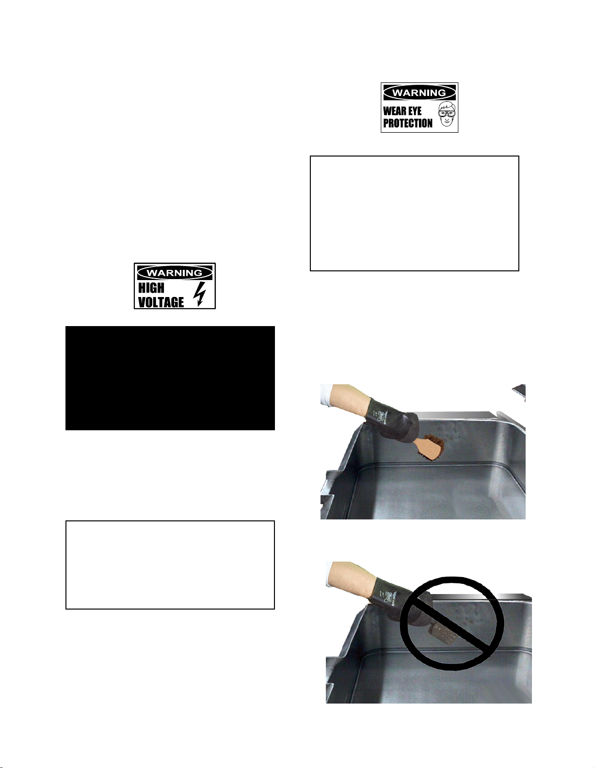
b. To remove any large amount of food left
in the pan, tilt the pan all the way up and
flush it with lukewarm water. Do not
damage the surface of the pan by
scraping it with a metal tool. Scratches
make the surface more difficult to clean,
and provide ideal breeding places for
bacteria.
Use a brush, sponge, cloth, plastic or
rubber scraper, or plastic wool to clean.
Don’t use metal implements or steel wool
when cleaning.
12
Page 13

OM-BPM-E
e. Rinse the pan very well with lukewarm water,
and drain it completely.
f. As part of the daily cleaning program, clean
all inside and outside surfaces that may
have been soiled. Remember to check such
parts as the undersides of the cover, the
electrical console and other more remote
spots. Clean between the pan body and the
consoles using the brush provided (P/N
058705).
g. Controls and the control console may be
cleaned with a damp cloth or sprayed with a
garden hose spray connected to city water
supply. Do not use a pressure sprayer
directly on the unit or electrical parts.
h. To remove materials stuck to the equipment,
use a brush, sponge, cloth, plastic or rubber
scraper, or plastic wool with the cleaning
solution. To make washing easier, let the
cleaning solution sit in the unit and soak into
the residue, or heat the solution briefly. Do
not use any gritty cleaner or metal tool that
might scratch the surface. Scratches make
the surface harder to clean, and also provide
places for bacteria to grow. Do not use steel
wool. Small bit of steel wool left in the
surface of the unit can cause rusting and
pitting.
i. The outside of the unit may be polished with
a recognized stainless steel cleaner such as
Zepper from the Zep Manufacturing
Company.
j. W hen the equipment needs to be sanitized,
use a sanitizing solution equivalent to one
that supplies 100 parts per million available
chlorine. Get advice about the best
sanitizing agent from you supplier of
sanitizing products.
k. Following supplier instructions, apply the
sanitizing agent after the unit has been
cleaned and drained. Thoroughly drain off
the sanitizer.
CAUTION
NEVER LEAVE A CHLORINE SANITIZER IN
CONTACT WITH STAINLESS STEEL
SURFACES FOR LONGER THAN 30
MINUTES. LONGER CONTACT CAN CAUSE
CORROSION.
l. After the unit has been cleaned, sanitized and
drained, let all surfaces air dry unless the unit
must be used again right away.
m. It is recommended that the unit be sanitized
just before use. Follow the directions of the
sanitizer supplier.
n. About once a week (more often if the water is
very hard), use a heavy duty cleaner to
remove any mineral deposits or film left by
hard water or foods. Follow the supplier’s
directions very carefully, and rinse the unit off
thoroughly, as soon as cleaning is finished.
CAUTION
KEEP CAUSTIC COMPOUNDS SUCH AS
FRYER BOILOUT CLEANERS AWAY FROM
ALUMINUM PARTS OF THE LID HINGE
SYSTEM AND THE COUNTERBALANCE
ASSEMBLY. HIGHLY CAUSTIC
COMPOUNDS COULD DAMAGE THIS
MATERIAL.
o. If especially difficult cleaning problems
persist, contact your cleaning product supplier
for help. The supplier has a trained technical
staff with laboratory facilities to serve you.
13
Page 14

OM-BPM-E
Maintenance
Your Braising Pan is designed to require minimum
maintenance, but certain parts may need
replacement after prolonged use. After installation,
no user adjustment should be necessary. If a
service need arises, only authorized personnel
should perform the work.
WARNING
ELECTRIC POWER ALWAYS SHOULD BE
SHUT OFF BEFORE WORK IS DONE ON
INTERNAL COMPONENTS
Service personnel should check the unit at least
once a year. This periodic maintenance should
include inspecting wires and connections and
cleaning inside the control console. At least twice a
year grease the two trunnion bearings and worm
gear.
Groen recommends the use of number two grade
LGI lithium grease. Add grease through the zerk
fittings on the gear hosing until grease flows out of
the bearings around trunion shaft. Also, add grease
in the gear to cover arc that is in contact with the
worm gear. Clean up excess grease.
WARNING
DISCONNECT ELECTRICAL POWER
FROM THE UNIT BEFORE ATTEMPTING
TO GREASE THE TRUNNION SHAFT.
A Service Log is provided with the warranty
information at the back of this manual. Each time
service is performed on your Groen equipment, enter
the date on which the work was done, what was
done, and who did it. Keep the manual with the
equipment for quick and easy reference.
WARNING
ELECTRICAL POWER MUST BE SHUT OFF BEFORE WORK IS DONE ON INTERNAL
COMPONENTS.
WARNING
USE OF ANY REPLACEMENT PARTS OTHER THAN THOSE SUPPLIED BY GROEN OR THEIR
AUTHORIZED DISTRIBUTORS CAN CAUSE INJURY TO THE OPERATOR AND DAMAGE TO THE
EQUIPMENT AND WILL VOID ALL WARRANTIES.
SERVICE PERFORMED BY OTHER THAN FACTORY-AUTHORIZED PERSONNEL WILL VOID ALL
WARRANTIES.
Troubleshooting
Your Groen Braising Pan will operate smoothly and efficiently if properly maintained. However, the following is a
list of checks to make in the event of a problem. If the actions suggested do not solve the problem, call your
authorized Groen Service Representative. For the phone number of the nearest agency, call your area Groen
representative or the Groen Parts and Service Department. If an item on the list is followed by <, the work should
only be performed by a qualified service representative.
SYMPTOM WHO WHAT TO CHECK
<<<< indicates items which must be performed by an authorized technician.
Pan will not heat, but
indicator light comes
on.
Auth Service
Rep Only
a. Heating elements for short circuit.<
<
<<
14
Page 15

OM-BPM-E
SYMPTOM WHO WHAT TO CHECK
<<<< indicates items which must be performed by an authorized technician.
Pan will not heat, and
indicator light will not
light
Pan continues to heat
after it reaches
desired temperature
Pan does not reach
desired temperature.
Rapid clicking noise
(chattering)
Uneven cooking due
to “hot spots.”
Uneven cooking due
to “cold spots.”
Pan is hard to tilt
(Manual Tilt Models)
Pan will not tilt
(Power Tilt Models)
User a. That power supply is on.
Auth Service
Rep Only
Auth Service
Rep Only
User a. Thermostat dial setting. Turn down if too high.
Auth Service
Rep Only
User a. Thermostat dial setting. Turn up if too low.
Auth Service
Rep Only
User a. For low voltage.
Auth Service
Rep Only
User a. That the pan body is level
Auth Service
Rep Only
User b. Gears for foreign materials, lubrication and alignment.
User a. That electrical power supply is on.
Auth Service
Rep Only
b. Fuses, accessible by removing caps on the side of the
control box.
c. For loose or broken wires.<
d. Thermostat functioning, by listening for a click when
the switch opens or closes.<
e. Contactor functioning.<
b. Thermostat functioning.
c. Thermostat calibration.<
d. Contactor, to determine if it is de-energized.<
b. Heating elements for ground short or open (burned
out) element.
c. Thermostat functioning, by listening for a click when
the switch opens or closes.<
d. Thermostat calibration.<
e. Contactor functioning.<
b. Contactor for dirt or corrosion on the contacts.<
a. For open (burned out) heating element.<
b. For overheated actuator motor. Wait 15 minutes for
motor to cool, then operate the power tilt.
c. For blown fuse on motor control circuit - Replace fuse
with Groen approved equal.<
d. For damaged DC rectifier and operating relays.<
e. Correct setting of upper and lower limit switches.<
<<<<
<
<<
<
<<
<
<<
<<<<
<
<<
<
<<
<
<<
<
<<
<
<<
<
<<
<
<<
<
<<
<
<<
<
<<
WARNING
ELECTRICAL POWER MUST BE SHUT OFF BEFORE WORK IS DONE ON INTERNAL
COMPONENTS.
WARNING
USE OF ANY REPLACEMENT PARTS OTHER THAN THOSE SUPPLIED BY GROEN OR THEIR
AUTHORIZED DISTRIBUTORS CAN CAUSE INJURY TO THE OPERATOR AND DAMAGE TO THE
EQUIPMENT AND WILL VOID ALL WARRANTIES.
SERVICE PERFORMED BY OTHER THAN FACTORY-AUTHORIZED PERSONNEL WILL VOID ALL
WARRANTIES.
15
Page 16

OM-BPM-E
Stand and Foot Assembly
Parts List
STAND & FOOT ASSEMBLY
Key Part #
1 CASTER KIT (SET OF 2 WITH BRAKE AND 2 W/O BRAKE) 146354
1 CASTER WITH BRAKE (W/O FOOT ADAPTER) 146513
1 CASTER WITHOUT BRAKE (W /O FOOT ADAPTER)-NOT SHOWN 146515
2 FOOT ADAPTER 146516
3 FLANGED FOOT (W/O FOOT ADAPTER) 146521
4 BULLET FOOT (W/O FOOT ADAPTER) 146628
5 FRICTION RING 146520
16
Page 17

OM-BPM-E
Cover and Counter Balance Assembly
Parts List
Key Qty COVER & COUNTERBALANCE ASSEMBLIES Part #
1 1 COVER ASSEMBLY, 30 GALLON 144812
1 1 COVER ASSEMBLY, 40 GALLON 144453
2 1 COUNTERBALANCE ASSEMBLY, 30 GALLON 145480
2 1 COUNTERBALANCE ASSEMBLY, 40 GALLON 144790
3 4 STUD WELD, 1/4"-20 X 1-1/4" 012589
4 4 WASHER, LOCK 3/8" 005618
5 4 SCREW, HEX HEAD CAP 3/8"-16 X 1" 005612
6 4 NUT, HEX 3/8"-16 005619
7 4 DOME NUTS, 1/4-20 090567
8 2 SCREW, TRUSS HEAD, #10-32 X 3/8" 004173
9 1 VENT COVER ASSY. MS17494
17
Page 18

OM-BPM-E
Pan and Element Cover Assembly
Parts List
KEY QTY DESCRIPTION PART NO.
PAN & HEATING ELEMENTS
1 1 PAN WELDMENT, 30 GALLON 145654
1 1 PAN WELDMENT, 40 GALLON 144789
2 1 ELEMENT COVER WELD ASSY., 30 GALLON 146186
2 1 ELEMENT COVER WELD ASSY., 40 GALLON 144343
3 15 HEATER CLAMPS, 30 GALLON 012844
3 18 HEATER CLAMPS, 40 GALLON 012844
4 1 CLAMP THERMOSTAT BULB 012968
5 2 CONDUIT HANGER, 30 GALLON 012852
6a 4 NUT, HEXAGON KEPS 1/4"-20 012940
6b 19 NUT, HEXAGON KEPS 5/16"-18, 30 GALLON 012941
6b 22 NUT, HEXAGON KEPS 5/16"-18, 40 GALLON 012941
6c 4 WASHER, FLAT
7 15 IN. WOVEN GLASS TAPE 045226
8 9 HEATER ELEMENTS, 30 GALLONS, 208V 145656
8 9 HEATER ELEMENTS, 30 GALLONS, 240V 146185
8 9 HEATER ELEMENTS, 30 GALLONS. 480V 145657
8 12 HEATER ELEMENTS, 40 GALLONS, 208V 145656
8 12 HEATER ELEMENTS, 40 GALLONS, 240V 146185
8 12 HEATER ELEMENTS, 40 GALLONS, 480V 145657
9 1 THERMOSTAT, HI-LIMIT 142755
10 2 NUT, HEXAGON KEPS #4-40 003121
11 1 HEATER ELEMENT HARNESS, 30 GALLON (NOT
SHOWN)
11 1 HEATER ELEMENT HARNESS, 40 GALLON (NOT
SHOWN)
144964
144976
18
Page 19

OM-BPM-E
Electrical Control Components
Parts List
19
Page 20

OM-BPM-E
Electrical Control Components
Parts List
ELECTRICAL CONTROL COMPONENTS
KEY QTY PART NO.
1 1 TERMINAL BLOCK [4-POLE] 088214
2 1 FUSE HOLDER [MAIN CONTROLS] 077854
3 1 FUSE [24VAC CONTROL, 3A, TYPE AG] 077853
4 1 TRANSFORMER, 208 OR 240 V UNITS 137441
4 1 TRANSFORMER,480 V UNITS 137694
5 2 SCREW, ROUND HEAD #8-32 X 1-1/4" 005056
6 1 CONTACTOR [4-POLE, 24VAC COIL VOLTAGE], 208/240/480V, 1/3 PH 119811
7 1 SCREW, ROUND HEAD #6-32 X 3/8" 009697
8 6 SCREW, SLOTTED HEX HEAD #8-32 X 3/8" 069789
9 1 TILT SW ITCH BRACKET WELD ASSY. 145689
10 1 INSULATION BARRIER 003490
11 1 TILT LIMIT SWITCH (HEAT CUT-OFF) 002982
12 1 POWER SWITCH WITH RED INDICATOR 144857
13 1 LIGHT, INDICATOR AMBER 24V 116384
14 1 LAMP GASKET 137434
15 1 THERMOSTAT ADAPTER 107172
16 1 THERMOSTAT GASKET 123585
17 1 CONTROL THERMOSTAT (ELECTRIC) 002180
18 2 SCREW, ROUND HEAD #4-40 X 3/4" 003122
19 2 NUT, HEXAGON KEPS #4-40 003121
20 2 WASHER, #6 INTERNAL TOOTH 013418
21 1 GROUND LUG 119829
22 1 THERMOSTAT KNOB 003908
23 1 TERMINAL BLOCK BOX BOTTOM 146207
24 1 TERMINAL BLOCK BOX 146205
25 1 SCREW HEX SLOTTED 069773
1 WIRING HARNESS CONTROL LOW VOLTAGE BPM-30,40E (NOT
SHOWN)
1 HIGH LIMIT THERMOSTAT (ELECTRIC) (NOT SHOWN) 142755
1 WIRING HARNESS POWER HIGH VOLTAGE BPM-40E (NOT SHOWN) 146193
1 HARNESS, ELEMENTS, 30 GALLON (NOT SHOWN) 144964
1 HARNESS, ELEMENTS, 40 GALLON (NOT SHOWN) 144976
144961
20
Page 21

OM-BPM-E
Trunnion Covers
Parts List
21
Page 22

OM-BPM-E
Trunnion Covers
Parts List
TRUNNION COVERS MANUAL TILT POWER TILT
KEY QTY PART NO. PART NO.
2 6 SCREW TRUSS HEAD 005764 005764
3 1 RIGHT TRUNNION SIDE PANEL 145688 145688
4 2 NUT HEX 005619 005619
5 2 WASHER LOCK 005618 005618
6 2 SCREW HEX HEAD CAP 005615 005615
7 1 RETAINING RING 124764 124764
8 1 FAUCET BRACKET 137738 137738
9 4 SCREW, 1/4-20 x 3/8" TRUSS 125609 125609
10 1 PILLOW BLOCK BOX 144314 144314
11 1 PILLOW BLOCK 002989 002989
13 1 SCREW-HEX SLOTTED 069773 069773
14 1 TERMINAL BLOCK BOTTOM 146207 146207
15 1 TERMINAL BLOCK BOX 146205 146205
16 1 ELECTRICAL PANEL COVER ASSY. 144762 144779
64 IN COVER GASKET (not shown) 145662 145662
22
Page 23

OM-BPM-E
Manual Tilt Assembly
Parts List
MANUAL TILT ASSEMBLY
KEY QTY Part No.
1 1 GEAR CARRIER 002624
2 1 SHAFT, HANDWHEEL 144834
3 1 GEAR, WORM 128001
4 1 GEAR SECTOR 009829
5 1 KEY GIB 012031
6 1 HANDWHEEL 012061
7 2 PIN ROLL 012614
8 1 SCREW SET SOCKET 012060
9 2 BEARING ROLLER 002790
10 1 BEARING SLEEVE 137239
11 1 PLUG PIPE 010286
14 1 FITTING GREASE 90 (NOT SHOWN) 012195
15 1 BUSHING SNAP (NOT SHOWN) 000453
16 2 WASHER LOCK 005618
17 2 SCREW HEX HEAD CAP 005612
23
Page 24

OM-BPM-E
Electric Tilt Assembly
Parts List
24
Page 25

OM-BPM-E
Electric Tilt Assembly
Parts List
KEY QTY POWER TILT COMPONENTS PART NO.
1 1 ELECTRIC TILT SHAFT 144791
2 1 POWER LIFT MOTOR 115V-FOR 480V BRAISING PANS 144792
2 1 POWER LIFT MOTOR 208/240V-FOR 208V OR 240V BRAISING PANS 144794
3 1 SHAFT COUPLING 144615
4 1 GEAR CARRIER ASSEMBLY 137880
4a 1 CARRIER GEAR 002624
4b 2 BEARING ROLLER 002790
4c 2 BEARING SLEEVE 137239
4d 1 PLUG PIPE 010286
4e 1 FITTING GREASE 90 012195
5 1 GEAR, WORM 128001
6 1 GEAR SECTOR 009829
6a 2 SCREW SET SOCKET 012060
7 1 KEY GIB 012031
8 1 PIN ROLL 012614
9 1 MOTOR BRACKET 146114
10 1 REAR MOTOR BRACKET 146117
11a 1 FUSE HOLDER [MOTOR] 077840
11b 1 FUSE [MOTOR, LP-CC-2 1/2] 144856
11c 1 RECTIFIER 145660
11d 2 RELAY [24VAC, DPST, N0]-2 REQ'D 119814
12 5 NUT HEX HEAD 1/4"-20 005601
13 5 WASHER LOCK 1/4" 005655
14 3 SCREW HEX HEAD CAP 1/4"-20 X 2-1/2" LONG 052584
15 2 SCREW HEX HEAD CAP 005609
16 2 WASHER LOCK 3/8" 005618
17 2 SCREW HEX HEAD CAP 3/8"-16 X 1" LONG 005612
18 1 ELECTRIC TILT SHAFT KEY 013386
1 HOLE PLUG-1" (NOT SHOWN) 146369
1 MANUAL OVERRIDE CRANK (NOT SHOWN) 145659
1 POWER SWITCH W/O INDICATOR (NOT SHOWN) 144858
2 TILT LIMIT SWITCH (POWER LIFT UP/DN -2 USED) (NOT SHOWN) 002982
1 TRANSFORMER (460/115, 300VA)-FOR 480V BRAISING PANS ONLY
(NOT SHOWN)
1 WIRE HARNESS,LOW VOLTAGE-FOR 208V OR 240V BRAISING
PANS (NOT SHOWN)
1 WIRE HARNESS-FOR 480V BRAISING PANS (NOT SHOW N) 146531
1 WIRE HARNESS-HIGH VOLTAGE-FOR 208V OR 240V BRAISING
PANS (NOT SHOWN)
1 WIRE HARNESS-HIGH VOLTAGE-FOR 480V BRAISING PANS (NOT
SHOWN)
051469
146194
146192
146532
25
Page 26

OM-BPM-E
Electrical Heater & Transformer Chart
Model Power No. Of
Heaters
BPM-30E
BPP-30E
BPM-40E
BPP-40E
11.5 kw 9 145656 146185 145657 137441 137441 137694
11.5 kw 9 145656 146185 145657 137441 137441 51469 &
15.3 kw 12 145656 146185 145657 137441 137441 137694
15.3 kw 12 145656 146185 145657 137441 137441 51469 &
NATIONAL FIRE PROTECTION ASSOCIATION
60 Battery March Park
Quincy, Massachusetts 02269
NFPA/70 The National Electrical Code
Heater Part Number Transformer Part Number
208 V 240 V 480 V 208 V 240 V 480 V
137694
137694
References
NATIONAL SANITATION FOUNDATION
3475 Plymouth Rd.
Ann Arbor, Michigan 48106
NSF/ANSI - Standard 4
Underwriters Laboratories, Inc.
333 Pfingsten Road
Northbrook, Illinois 60062
UL/ANSI Standard 197
26
Page 27

OM-BPM-E
Diagrams & Schematics
BPM-30E 208, 240 and 480 Volts
27
Page 28

OM-BPM-E
Diagrams & Schematics Continued
BPP-30E 208 and 240 Volt
28
Page 29

OM-BPM-E
Diagrams & Schematics Continued
BPP-30E 480 Volt
29
Page 30

OM-BPM-E
Diagrams & Schematics, Continued
BPM-40E 208, 240 and 480 Volt
30
Page 31

OM-BPM-E
Diagrams & Schematics, Continued
BPP- 40E 208 and 240 Volt
31
Page 32

OM-BPM-E
Diagrams & Schematics, Continued
BPP- 40E 480 Volt
32
Page 33

OM-BPM-E
Service Log
Model No. Purchased From
Serial No. Location
Date Purchased Date Installed
Purchase Order No. For Service Call
Date Maintenance Performed Performed by
33
Page 34

OM-BPM-E
LIMITED WARRANTY TO
COMMERCIAL PURCHASE*
(U.S. & Canadian Sales Only.)
Groen® warrants to original commercial purchaser/users that foodservice equipment manufactured by Groen®
(³Groen® Equipment²) other than CapKold® foodservice equipment, shall be free from defects in material and
workmanship for twelve (12) months from the date of installation or fifteen (15) months from date of shipment from
Groen®, whichever date first occurs (the “Warranty Period”), in accordance with the following terms and
conditions:
I. This warranty is limited to replacement parts and related labor for Groen® Equipment located at its original place
of installation in the United States and Canada.
II. Damage to Groen® Equipment that occurs during shipment must be reported to the carrier and is not covered
under this warranty. The reporting of any damage during shipment is the sole responsibility of the commercial
purchaser/user of such Groen® Equipment.
TM
III. For Groen® Convection Combo
TM
Steamers and HyPlus
Pressureless Steamers, Groen® further warrants to the original commercial purchaser/users
Steamer-Ovens, HyPerSteamTM Convection
of such Groen® Equipment that the atmospheric steam generators or boilers contained in such Groen® Equipment
shall be free from defects in material and workmanship for twenty-four (24) months from the date of installation or
twenty-seven (27) months from date of shipment from Groen®, whichever date first occurs, provided that: (a) the
original purchaser/user shall have also purchased and installed a Groen® PureSteem Water Treatment System
use in connection with such Groen® Convection Combo
HyPlus
TM
Pressureless Steamer on or before the date such Groen® Equipment was installed, (b) the original
TM
Steamer-Oven, HyPerSteamTM Convection Steamer or
TM
for
purchaser/user has continuously used such Water Treatment System in connection with such Groen® Equipm ent from
the date of installation, and ©) the commercial purchaser/user shall have maintained such Water Treatment System
in accordance with the maintenance and filter cartridge replacement recommendations of Groen®, and otherwise
maintained such Oven or Steamer in accordance with all other operational and maintenance recommendations of
Groen®.
TM
IV. For Groen® SmartSteam
to the original commercial purchaser/users of SmartSteam
Boilerless Steamers and Vortex® Connectionless Steamers, Groen® further warrants
TM
Boilerless Steamers and Vortex® Connectionless
Steamers shall be free from defects in material and workmanship for twenty-four (24) months from the date of
installation or twenty-seven (27) months from the date of shipment from Groen, whichever date first occurs. This
warrants Groen® Vortex® Connectionless Steamers that were shipped after March 15, 2003 and SmartSteam
TM
Boilerless Steamers that were shipped after May1, 2003.
V. Groen® further warrants to the original commercial purchaser/users of Groen® Convection Combo
TM
SteamerOvens that the electronic relay and control board contained in such Groen® Convection ComboTM Steamer-Oven shall
be free from defects in material and workmanship for twenty-four (24) months from the date of installation or twentyseven (27) months from date of shipment from Groen®, whichever date first occurs.
VI. During the Warranty Period, Groen®, directly or through its authorized service representative, will either repair
or replace, at Groen¹s sole election, any Groen® Equipment determined by Groen® to have a defect in material or
workmanship. As to any such warranty service during the Warranty Period, Groen® will be responsible for related
reasonable labor and portal to portal transportation expenses (time & mileage) incurred within the United States and
Canada.
34
Page 35

OM-BPM-E
VII. This warranty does not cover boiler maintenance, calibration,
periodic adjustments as specified in operating instructions or manuals, consumable parts (such as scraper blades,
gaskets, packing, etc.), and labor costs incurred for removal of adjacent equipment or objects to gain access to
Groen® Equipment. This warranty does not cover defects caused by improper installation, abuse, careless operation,
or improper maintenance of Groen® Equipment. This warranty does not cover damage to Groen® Equipment caused
by poor water quality or improper boiler maintenance.
VIII. THIS WARRANTY IS EXCLUSIVE AND IS IN LIEU OF ALL OTHER WARRANTIES,
EXPRESSED OR IMPLIED, INCLUDING ANY IMPLIED WARRANTY OF MERCHANTABILITY OR FITNESS FOR
A PARTICULAR PURPOSE, EACH OF W HICH IS HEREBY EXPRESSLY DISCLAIMED. THE REMEDIES
DESCRIBED ABOVE ARE EXCLUSIVE AND IN NO EVENT SHALL GROEN® BE LIABLE FOR SPECIAL,
CONSEQUENTIAL, OR INCIDENTAL DAMAGES FOR THE BREACH OR DELAY IN PERFORMANCE OF THIS
WARRANTY.
IX. Groen® Equipment is for commercial use only. If sold as a component
of another (O.E.M.) manufacturer¹s equipment, or if used as a consumer product, such Equipment is sold AS IS and
without any warranty.
TM
*Covers Groen® Equipment (other than CapKold® foodservice equipment, SmartSteam
Steamers and Vortex® Connectionless Steamers) ordered after September 11, 2001.
Boilerless
35
Page 36

OM-BPM-E
GROEN® LIMITED EXTENDED WARRANTY COVERAGE*
(U.S. & Canadian Sales Only)
Limited Extended Warranty Coverage is available on all standard Groen® Equipment (other than CapKold®
foodservice equipment) covered by the above Groen® Limited Warranty. Commercial purchasers/users of Groen®
Equipment may elect to extend the standard limited warranty to cover parts, labor and portal to portal transportation
costs (time and mileage) for an additional twelve (12) or twenty four (24) month period, in addition to the time period
of the standard limited warranty described above. Limited Extended Warranty Coverage is not available to extend
the supplemental limited warranty for:
TM
(a) atmospheric steam generators or boilers contained in Groen® Convection Combo
HyPerSteam
contained in Groen® Convection Combo
TM
Convection Steamers and HyPlusTM Pressureless Steamers, or (b) electronic relay and control boards
TM
Steamer-Ovens, or ©) Groen® SmartSteamTM Boilerless Steamers, or
(d) Vortex® Connectionless Steamers.
Cost of Extended Coverage
Five percent (5.0%) of the LIST PRICE of the Groen® Equipment to be covered by the Limited Extended Warranty
for each additional twelve (12) months of limited extended warranty coverage. The five percent (5.0%) of the LIST
PRICE charge will be the net invoice amount for each year of Limited Extended Warranty Coverage purchased.
Conditions of Coverage
(1) Limited Extended Warranty Coverage must be purchased at the time the Groen® Equipment to be covered
is purchased.
Steamer-Ovens,
(2) All conditions and limitations on the Standard Limited Warranty Coverage apply to the Limited Extended
Warranty Coverage. See above for details of conditions and limitations on the Standard Warranty Coverage.
TM
*Covers Groen® Equipment (other than CapKold® foodservice equipment, SmartSteam
Boilerless
Steamers and Vortex® Connectionless Steamers) ordered after September 11, 2001.
36
Page 37

1055 Mendell Davis Drive
Jackson, MS 39272
Telephone 601 372-3903
FAX 601 373-9587
OM-BPM-E (Revised 10/03)
Part Number 145340 Rev A
 Loading...