

Groen BPM-30G, BPM-40G Operation Manual
OPERATOR/SERVICE MANUAL
IMPORTANT INFORMATION, KEEP FOR OPERATOR
This manual provides information for:
MODELS
BPM-30/40G(CE) International
ECLIPSE™ ERGONOMIC
TILTING BRAISING PAN
· Stainless Steel
· Manual Tilt
· Gas Heated
READ, UNDERSTAND AND FOLLOW THE INSTRUCTIONS AND
WARNINGS CONTAINED IN THIS MANUAL.
FOR YOUR SAFETY
Do not store or use gasoline or other flammable vapors
and liquids in the vicinity of this or any other appliance.
POST IN A PROMINENT LOCATION
Instructions to be followed in the event user smells gas.
This information shall be obtained by consulting your
local gas supplier. As a minimum, turn off the gas and
call your gas company and your authorized service agent.
Evacuate all personnel from the area.
WARNING
Improper installation, adjustment, alteration, service or
maintenance can cause property damage, injury or death.
Read the installation, operating and main
thoroughly before installing or servicing this equipment.
NOTIFY CARRIER OF DAMAGE AT ONCE
It is the responsibility of the consignee to inspect the container upon receipt of
same and to determine the possibility of any damage, including concealed damage. Unified Brands suggests that if you are suspicious of damage to make a
notation on the delivery receipt. It will be the responsibility of the consignee to file
a claim with the carrier. We recommend that you do so at once.
tenance instructions
.ECNEREFER ERUTUF ROF DENIATER EB TSUM LAUNAM SIHT
Manufacture Service/Questions 888-994-7636.
Information contained in this document is known to be current and accurate at the time
of printing/creation. Unified Brands recommends referencing our product line websites,
unifiedbrands.net, for the most updated product information and specifications.
PART NUMBER 160812, REV. E (11/08)
PART NUMBER 160812, REV. C (06/07)
1055 Mendell Davis Drive
Jackson, MS 39272
888-994-7636, fax 888-864-7636
groen.com

IMPORTANT — READ FIRST — IMPORTANT
THESE APPLIANCES MUST BE INSTALLED BY A COMPETENT PERSON IN CONFORMITY WITH THE
INSTALLATION AND SERVICING INSTRUCTIONS AND NATIONAL REGULATIONS IN FORCE AT THE TIME.
PARTICULAR ATTENTION MUST BE PAID TO THE FOLLOWING:
I. E. E. REGULATIONS FOR ELECTRICAL INSTALLATIONS
ELECTRICITY AT WORK REGULATIONS
GAS SAFETY (INSTALLATION & USE REGULATIONS
HEALTH AND SAFETY AT WORK ACT
FIRE PRECAUTIONS ACT
LOCAL AND NATIONAL BUILDING REGULATIONS
DETAILED RECOMMENDATIONS ARE CONTAINED IN INSTITUTE OF GAS ENGINEERS PUBLISHED
DOCUMENTS: IGE/UP/1, IGE/UP/2, BS6173 AND BS5440.
THESE APPLIANCES HAVE BEEN CE-MARKED ON THE BASIS OF COMPLIANCE WITH THE GAS
APPLIANCE DIRECTIVE, EMC AND LOW VOLTAGE DIRECTIVE FOR THE COUNTRIES, GAS TYPES AND
PRESSURES AS STATED ON THE DATA PLATE.
WARNING: TO PREVENT SHOCKS, ALL APPLIANCES WHETHER GAS OR ELECTRIC, MUST BE
EARTHED.
ON COMPLETION OF THE INSTALLATION, THESE INSTRUCTIONS SHOULD BE LEFT WITH THE
ENGINEER-IN-CHARGE FOR REFERENCE DURING SERVICING. FURTHER TO THIS, THE USERS
INSTRUCTIONS SHOULD BE HANDED TO THE USERS AND THE INSTALLER SHOULD INSTRUCT THE
RESPONSIBLE PERSON(S) IN THE CORRECT OPERATION AND MAINTENANCE OF THE APPLIANCE.
EMPHASIS SHOULD BE MADE WITH REGARD TO SAFE OPERATION OF DRAIN VALVE.
IT IS MOST IMPORTANT THAT THESE INSTRUCTIONS BE CONSULTED BEFORE INSTALLING AND
COMMISSIONING THE APPLIANCE. FAILURE TO COMPLY WITH THE SPECIFIED PROCEDURES MAY
RESULT IN DAMAGE OR THE NEED FOR A SERVICE CALL.
CAUTION: SHIPPING STRAPS ARE UNDER TENSION AND CAN SNAP BACK WHEN CUT.
CAUTION: UNIT WEIGHS 420 TO 560 LB. (165 TO 255 KG). FOR SAFE HANDLING, INSTALLER
SHOULD OBTAIN HELP AS NEEDED, OR EMPLOY APPROPRIATE MATERIALS HANDLING
EQUIPMENT (SUCH AS A FORKLIFT, DOLLY, OR PALLET JACK) TO REMOVE THE UNIT
FROM THE SKID AND MOVE IT TO THE PLACE OF INSTALLATION.
WARNING: INSTALLATION OF THE BRAISING PAN MUST BE DONE BY PERSONNEL QUALIFIED TO
WORK WITH GAS AND ELECTRICITY. IMPROPER INSTALLATION CAN RESULT IN INJURY
TO PERSONNEL AND/OR DAMAGE TO EQUIPMENT.
WARNING: THIS UNIT IS DESIGNED FOR COMMERCIAL USE. NEVER USE HOME OR RESIDENTIAL
GRADE GAS CONNECTIONS. THEY DO NOT MEET GAS CODES AND COULD BE
HAZARDOUS.
DANGER: ELECTRICALLY GROUND THE UNIT AT THE TERMINAL PROVIDED. FAILURE TO GROUND
UNIT COULD RESULT IN ELECTROCUTION AND DEATH.
WARNING: KEEP THE APPLIANCE AREA FREE AND CLEAR OF COMBUSTIBLE MATERIALS.
CAUTION: BE SURE ALL OPERATORS READ, UNDERSTAND AND FOLLOW THE OPERATING
INSTRUCTIONS, CAUTIONS AND SAFETY INSTRUCTIONS CONTAINED IN THIS MANUAL.
CAUTION: KEEP FLOORS IN BRAISING PAN WORK AREA CLEAN AND DRY. IF SPILLS OCCUR,
CLEAN IMMEDIATELY TO AVOID THE DANGER OF SLIPS OR FALLS.
WARNING: WHEN TILTING BRAISING PAN FOR PRODUCT TRANSFER:
1) USE CONTAINER DEEP ENOUGH TO CONTAIN AND MINIMIZE PRODUCT SPLASHING.
2) PLACE CONTAINER ON STABLE, FLAT SURFACE, AS CLOSE TO PAN AS POSSIBLE.
2 OM/SM-BPM-G

3) STAND TO SIDE OF PAN WHILE POURING — NOT DIRECTLY IN POUR PATH OF HOT
CONTENTS.
4) RETURN PAN BODY TO LEVEL POSITION AFTER CONTAINER IS FILLED OR
TRANSFER IS COMPLETE.
5) DO NOT OVER FILL CONTAINER. AVOID DIRECT SKIN CONTACT WITH HOT
CONTAINER AND ITS CONTENTS.
WARNING: DO NOT HEAT AN EMPTY PAN FOR MORE THAN 5 MINUTES AT A SETTING HIGHER
THAN 300ºF (150ºC).
WARNING: IF THE PAN CONTAINS ITEMS IN SAUCE OR MELTED FAT, THEY CAN SLIDE FORWARD
SUDDENLY DURING TILTING AND CAUSE THE HOT LIQUID TO SPLASH OUT.
WARNING: AVOID ALL DIRECT CONTACT WITH HOT FOOD OR WATER IN THE PAN. DIRECT
CONTACT COULD RESULT IN SEVERE BURNS.
WARNING: IT IS RECOMMENDED THAT WATER AND SOLUTIONS BE KEPT OUT OF CONTROLS AND
BURNERS. DO NOT USE HIGH PRESSURE SPRAY DIRECTLY ON THE CONTROL CONSOLE,
ELECTRICAL CONNECTIONS AND BURNERS. USE A GARDEN HOSE SPRAY CONNECTED
TO CITY WATER SUPPLY.
CAUTION: MOST CLEANERS ARE HARMFUL TO THE SKIN, EYES, MUCOUS MEMBRANES AND
CLOTHING. PRECAUTIONS SHOULD BE TAKEN TO WEAR RUBBER GLOVES, GOGGLES
OR FACE SHIELD AND PROTECTIVE CLOTHING. CAREFULLY READ THE WARNINGS AND
FOLLOW THE DIRECTIONS ON THE LABEL OF THE CLEANER TO BE USED.
WARNING: BEFORE REPLACING ANY PARTS, DISCONNECT THE UNIT FROM THE ELECTRIC POWER
SUPPLY AND CLOSE THE MAIN GAS COCK. ALLOW FIVE MINUTES FOR UNBURNED GAS
TO VENT. FAILURE TO DISCONNECT COULD RESULT IN ELECTROCUTION AND DEATH.
CAUTION: USE OF ANY REPLACEMENT PARTS OTHER THAN THOSE SUPPLIED BY GROEN OR
AUTHORIZED DISTRIBUTORS CAN CAUSE INJURY TO THE OPERATOR AND DAMAGE TO
THE EQUIPMENT AND WILL VOID ALL WARRANTIES.
IMPORTANT: Service performed by other than factory authorized personnel will void all warranties.
OM/SM-BPM-G 3

Table of Contents
IMPORTANT OPERATOR WARNINGS (READ FIRST) ............................................. 2
REFERENCES ............................................................................. 4
EQUIPMENT DESCRIPTION ................................................................. 5
1. INSTALLATION ......................................................................... 7
2. ASSEMBLY AND COMMISSIONING ........................................................10
3. SERVICING AND CONVERSION .......................................................... 12
4. USER INSTRUCTIONS .................................................................. 17
5. CLEANING ........................................................................... 19
6. SAFETY PRECAUTIONS ................................................................ 20
7. MAINTENANCE ........................................................................ 20
8. TROUBLESHOOTING ................................................................... 21
9. PARTS LIST .......................................................................... 23
10. SERVICE LOG ........................................................................ 35
References
Canadian Standards Association
8501 East Pleasant Valley Rd.
Cleveland, Ohio 44131
Z83-11 Gas FoodService Equipment
Z223.1 National Fuel Gas Code
American National Standards Institute
1403 Broadway
New York, New York 10018
Canadian Gas Association
55 Scarsdale Road
Don Mills, Ontario M3B 2 R3
National Fire Protection Association
60 Battery March Park
Quincy, Massachusetts 02269
NFPA/54 Installation of Gas Appliances &
Gas Piping
NFPA/70 The National Electrical Code
NFPA/96 Ventilating Hoods
National Sanitation Foundation
3475 Plymouth Road
Ann Arbor, Mic
higan 48106
Underwriters Laboratories, Inc.
333 Pfingsten Road
Northbrook, Illinois 60062
NSF INTERNATIONAL
789 N. Dixboro Rd.
P.O. Box 130140
Ann Arbor, Michigan 48113-0140
4 OM/SM-BPM-G
Equipment Description
The following dimensions apply to CE model BPM braising pans:
Model Width Depth Height Weight (Kg)
BPM-30G 984 mm 1010 mm 1100 mm 190
BPM-40G 1226 mm 1010 mm 1100 mm 255
Groen™ Gas-HeatedEclipse™ Ergonomic Tilting
Braising Pans provide a stainless steel pan
equipped with patented heat transfer fins,
burner/combustion chamber, hand-operated or
electric powered tilting mechanism, thermostatic
controls, and hi nged cover. Eclipse serves as
braising pan, griddle, fry pan, oven, kettle, bainmarie and food warmer/server, can be adapted
for use as a non-pressure steamer and can be
used to stir-fry, reheat and saute foods.
The pan body is made from heavy-duty stainless
steel welded into one solid piece, with a polished
interior and exterior. A pouring lip is welded to the
front wall. The cooking surface is a stainless steel
clad plate fitted
with welded heat transfer fins
which assureuniform heat transfer over the entire
surface. The gas burner/combustion chamber
supplies the heat.
Aneasily operatedworm andgear mechanism tilts
the pan and provides precise control for pouring or
dumping thecontents of the pan. This hand-wheel
controlled mechanism is located in a stainless
steel consoleto the right of thepan body. Toassist
cleaning, the panbody can be tilted past the
vertical position. When the pan is tilted, the
burners shut off automatically.
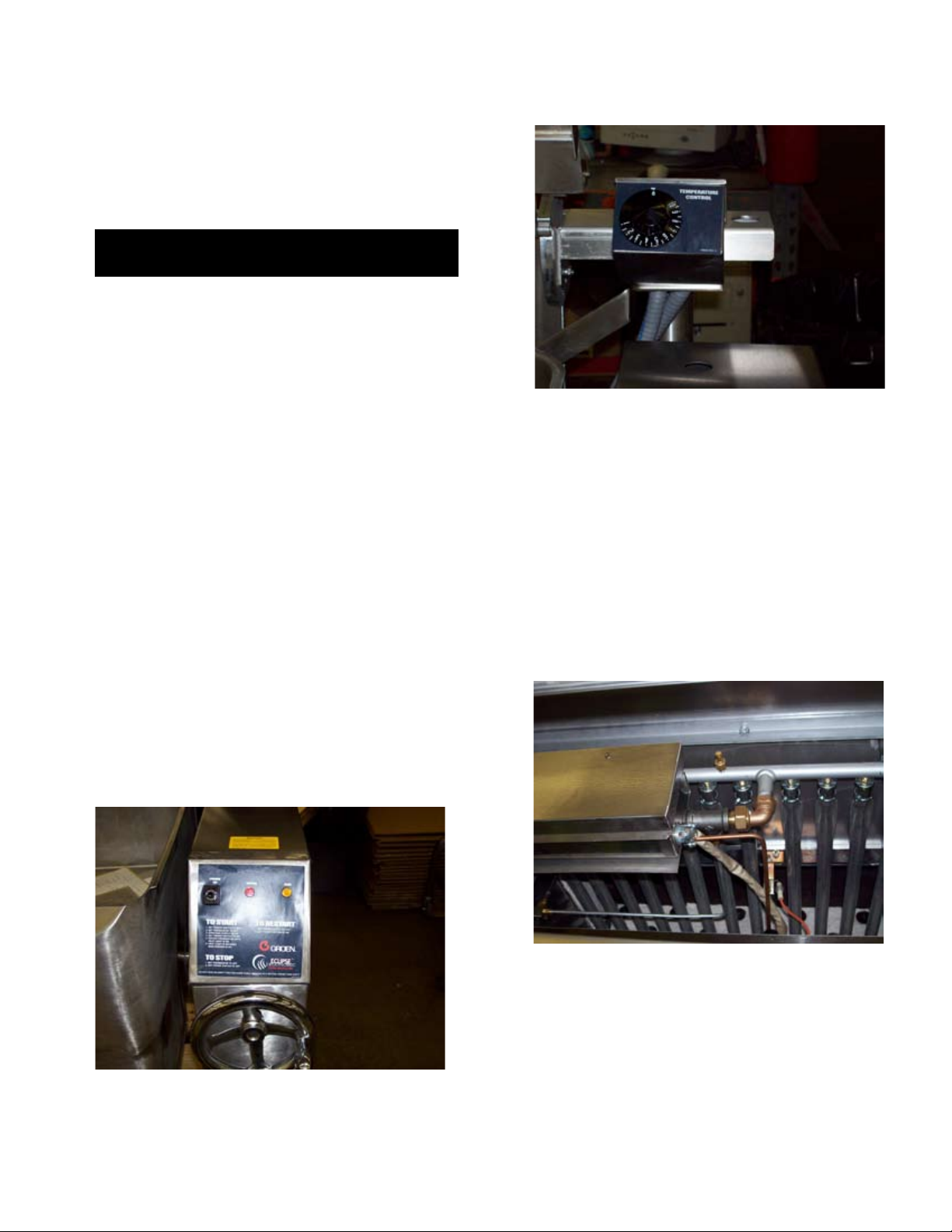
The thermostat provides automatic control of
cooking temperature. Operating the thermostat
dial on the front of the control console turns the
heat on or off and s
ets the pan temperature.
A vented,heavy gauge, one-piece, stainless steel
cover with a condensate drip shield on the rear
edge is standard on the Braising Pan. A fully
enclosed, torsion bar type counterbalance
provides easy operation to open the cover and to
maintain it open at any position. The coveropens
to theback and is hingedto theframe, so itmoves
independently of the pan body.
The braising pan ismounted onan open-leg frame
fabricated from tubular stainless steel. It has an
ignitionsystem that uses electronic spark ignition.
Options available with these models are:
1. Fill faucet with swingspout. (Leftor rightmounted)
- specify single or double pantry
2. Fill faucet with 48" or 60" spray hose assembly
(left or right mounted) - s
pecify single or double
pantry
3. Flanged Feet
4. Fold-down work tray (pan support) mounted on
right side.
5. 2” Tangent draw-off (Factory-installed must be
indicated on initial order)
6. Steamer Insert set.
7. Steamer Pan Carrier.
8. Pouring Lip Strainer.
9. Strainer for 2" TDO valve.
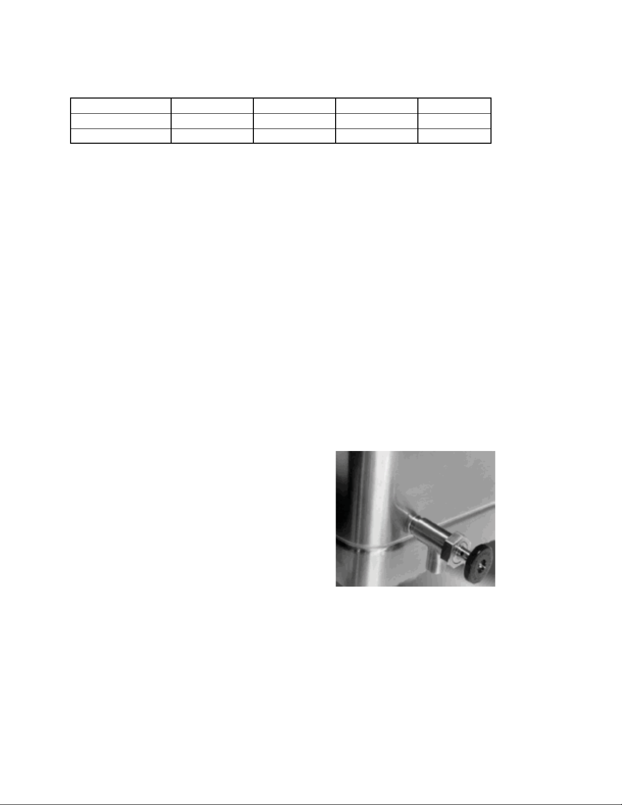
Optional Tangent Draw-Off
OM/SM-BPM-G 5
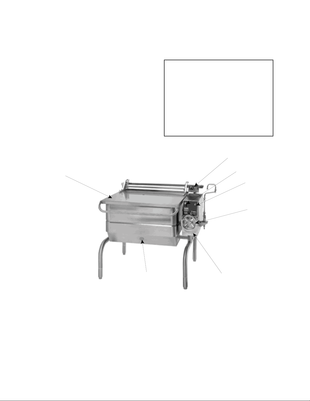
OM-BPM-G
ThermostatThermostat
Power
Switch
Cover
Indicator
Light
Manual Tilt
Handwheel
Stainless Steel
Console
The unit will arrive completely assembled,
on a heavy skid, in a heavy cardboard carton.
Immediately upon receipt, inspect the carton
for damage. Report any apparent shipping
damage or an incorrect shipment to the
delivery agent.
When installation is to begin, get someone to
assist in removing the carton. Lift it straight up
and away from the unit. Do not simply raise it
and push backwards - it could damage the unit.
Write down the model number, serial number,
and installation date of your unit, and keep
this information for future reference. Space for
these entries is provided at the top of the
Service Log in this manual.
Cut the straps holding the unit on the skid, and lift
the unit straight up off the skid.
CAUTION
SHIPPING STRAPS ARE UNDER TENSION
AND CAN SNAP BACK WHEN CUT.
UNIT WEIGHS 420 TO 560 LB (190 TO 255
KG). FOR SAFE HANDLING, INSTALLER
SHOULD OBTAIN HELP AS NEEDED, OR
EMPLOY APPROPRIATE MATERIALS
HANDLING EQUIPMENT (SUCH AS A
FORKLIFT, DOLLY, OR PALLET JACK) TO
REMOVE THE UNIT FROM THE SKID AND
MOVE IT TO THE PLACE OF INSTALLATION.
The unit is strapped to a skid, and shipped in a heavy cardboard carton.
(Shown is model BPM-40G with optional right side mounted, double pantry faucet assembly.)
Flame Observation
Port
Inspection & Unpacking
6 OM/SM-BPM-G

1. Installation
The following information pertains to the CE model BPM-G, and replaces or augments the information provided in
OM-BPM. These appliances must be installed by a competent person in conformity with the installation and
servicing instructions and national regulations in force at the time. Particular attention must be paid to the
following:
I. E. E. Regulations for Electrical Installations
Electricity at Work Regulations
Gas Safety (Installation & Use Regulations
Health and Safety at Work Act
Fire Precautions Act
Local and National Building Regulations
Detailed recommendations are contained in institute of gas engineers published documents: IGE/UP/1, IGE/UP/2,
BS6173 AND BS5440.
OM/SM-BPM-G 7
1.1
1.1.1
1.1.2
1.1.3
1.1.4
1.1.5
Installing Clearances
Vertical clearance of at least 1000 mm should be
allowed between the top edge of the flue outlet and
any overlying surface.
Adequate ventilation, whether natural or
mechanically induced, must be provided to ensure a
supply of fresh air for gas combustion, and to
facilitate effective removal of the products of
combustion.
Ventilation recommendations for catering appliances
are provided in BS 5440 : 2. Furthermore, guidance
on the column of ventilation air required for different
types of catering equipment to ensure sufficient
room ventilation is provided at right.
For multiple installations, the requirements for
individual appliances should be added together.
Installation should be made in accordance with local
and national regulations applying at the time. A
competent installer must be employed.
The appliance flue discharges horizontally from the
1.1.7
The gas connection for a unit on casters must be made
with a quick-disconnect device that complies with
ANSI Z21.41 - CSA 6.9.
1.1.6
For a unit on casters, the installation shall be made with
a connector that complies with the standard for
Connectors for Moveable Gas Appliances, ANSI Z21.69
- CSA 6.16. Restrain movement of the unit by attaching
a cable or chain to the eyelet provided at the back of
the frame and anchor the cable or chain to the wall or
floor. Make the length and location of the cable such
that the unit cannot pull on the gas connection while
the cable is connected or quick-disconnect.
rear of the unit. It must not be directly connected to
any flue, mechanical extraction system, ducting, etc.,
which leads to the outside of the building. The
appliance is best discharged under an open canopy
connected with a ventilating system.
1.2 Gas Supply
Incoming service must be of sufficient size to supply
full rate without excessive pressure drop. A gas
meter is connected to the service pipe by the gas
supplier.
Any existing meter should be checked by the
supplier to ensure that the meter has the capacity for
passing the required rate of gas for the braising pan
in addition to any other gas equipment installed.
EQUIPMENT
Ventilation Rate Required
m³/min ft³/min
Range, Unit Type 17 600
Pastry Oven 17 600
Fryer 26 900
Grill 17 600
Steak Grill 26 900
Boiling Pan 17 600
Steamer 17 600
Sterilizing Sink 14 500
Bain-Marie 11 400
Tea/Coffee Machine 8.5-14 300-500
The appliance governor is incorporated in the gas
control valve which is situated in the left control
cabinet. The control valve governor is suitable for
both natural and propane gases without conversion.
Installation pipework should be fitted in compliance
with IEGE/UP/2. The pipework should not be smaller
than the gas inlet connection (Rp½ [½” B.S.P.]).
An isolating cock must be located close to the
appliance to allow shut-down during emergencies or
service. Installation must be tested for gas
soundness and purged as specified in IGE/UP/1.
1.3 Electrical Supply
This unit is designed for connection to fixed wiring.
A suitably rated isolating switch with contact
separation of at least three millimeters on both poles,
must be fitted to the installation.
The wiring must be executed in accordance with
Power supply to this unit must be 230V, 1 Phase, 50/60hz
with wiring suitable for an electronic load of 50 watts.
the regulations listedinside the cover page of this
manual supplement.
Cable entry is at the control box on the rear right side
of the appliance. Access to the terminals is gained by
removing terminal block cover.
WARNIN
G
THIS APPLIANCE MUST BE EARTHED.
Minimum
Clearances
Recommended
Clearances
Left Side 0mm
0mm
77mm
51mm (2”) for service,
153mm (6”) when faucet is
installed on left side
Right Side
305-405mm (12-16”),
153mm (6”) when faucet is
installed on right side
Rear
305mm (12") for service
Fig. 1 Fig. 2
8 OM/SM-BPM-G
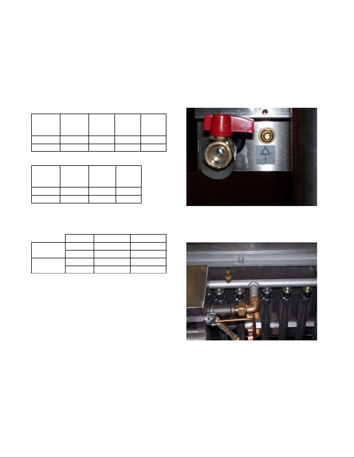
Gas is connected at the rear of the control
console.
1.4 Water Supply
Not applicable to these appliances ezcept for
optional faucets..
1.5 Gas System Performance
The tables below provide the total Gas Rates,
Injector Diameters and Pressure Adjustments for
model BPM-G (CE) using natural (G20) and
propane (G31) gas sources.
Total Gas Rate
Model
Natural
(G20)
KW
Natural
BTU/hr
Propane
(G31)
KW
Propane
BTU/hr
BPM-30G
26.1 89,100 26.1 89,100
BPM-40G
36.1 123,300 36.1 123,300
Injector Diameters-Natural & Propane Gas
Model
Natural
Gas G20
(mm)
Propane
Gas G31
(mm)
No. of
Orifices
(Injectors)
BPM-30G
1.5 0.97 11
BPM-40G
1.5 0.97 15
Gas Pressure Adjustment
A pressure test point is fitted on the burner manifold
and on the gas control valve.
Model BPM-30G BPM-40G
NATURAL
GAS G20
mbar 8.0 8.0
in. WC 3.2 3.2
PROPANE
GAS G31
mbar 19.4 19.4
in. WC 7.8 7.8
NOTE: With reference to the gas rate, pressure
adjustments and conversions, this appliance is
CE-approved for use with the following gases:
a) Gas Category I2H, G20 natural gas may be
supplied to the appliance in Austria, Denmark,
Finland, Greece, Iceland, Italy, Luxembourg,
Norway, Portugal, Spain, Sweden, Switzerland
and the United Kingdom.
b) Gas Category I3P, G31 propane gas may be
supplied to the appliance in Germany, Ireland,
the Netherlands, Portugal, Spain, Switzerland
and the United Kingdom.
Use of the appliance with non-approved gases in a
listed country, or use in other countries will void CE
certification.
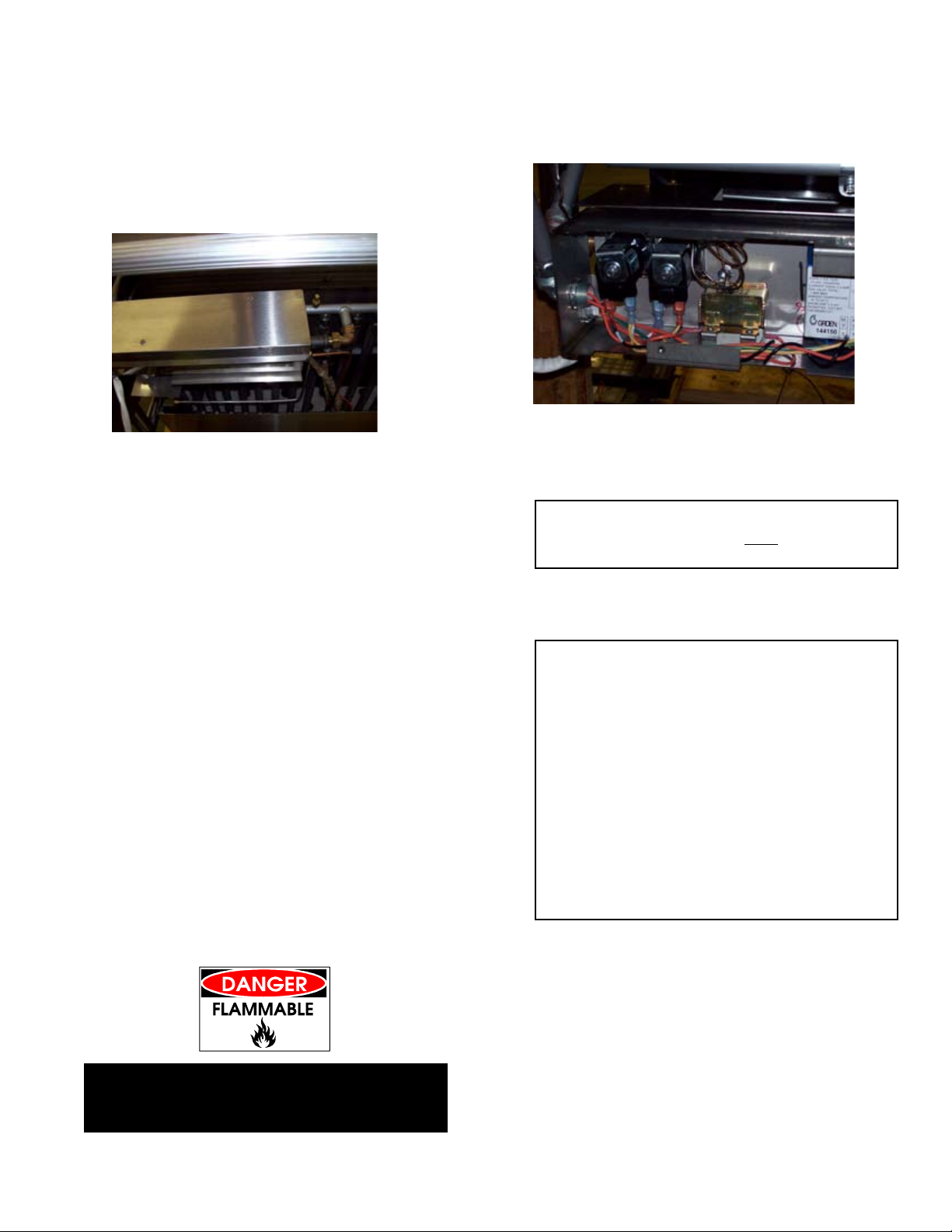
1.6 Burner Adjustment
The burner primary airflow may be adjusted by
loosening the screw and sliding the aerator forward
or backward. (See photograph)
Fig. 3
Fig. 4
OM/SM-BPM-G 9
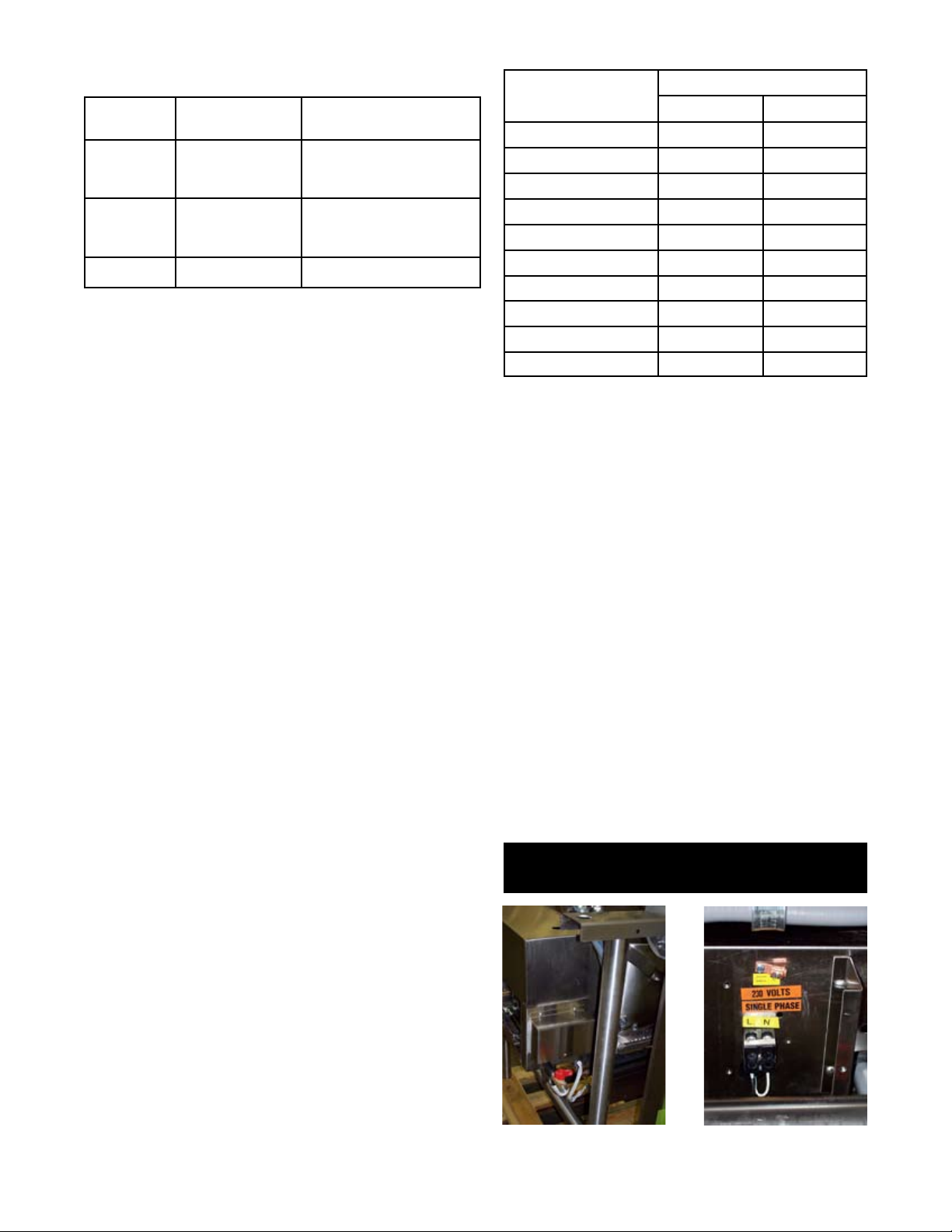
Main (Lower) Control Box
Upper Control Box
Connect a gauge to check pressure at the gas
manifold.
2. Assembly and Commissioning
2.1 Electrical Supply
Before commissioning the appliance, ensure that the
electrical installation has been performed in
compliance with relevant regulations. See
Paragraph 1.3, above.
WARNING
THIS APPLIANCE MUST BE EARTHED.
2.2 Pre-Commissioning Check
a) Remove literature and packing materials from
the interior and exterior of the unit.
b) Put enough water into the pan to cover the
c) Verify that the rear heat shield panel is in place.
bottom to a depth of 6-12mm. With the pan
body in the horizontal position, note how the
water lies in the pan, to confirm that the pan was
leveled properly during installation.
2.3 Operating the Braising Pan
2.3.1 Lighting Sequence
a) Put water in the pan (6 to 12 mm deep)
b) Check that gas and electricity mains are on.
c) Turn the toggle switch (Main Control Box) to the
“ON” position. The power neon (Main Control
Box) will illuminate.
d) Turn the thermostat (Upper Control Box) to the
desired setting.
e) Observe that the burners light by the lighting of
the heat neon (Main Control Box) (approximately
10-15 seconds).
f) Should the unit fail to light, turn the unit off and
wait for one or two minutes before attempting to
switch it on again. NOTE: Burner “ON” verification
can be confirmed by careful observation through
the Flame Observation Port. See Illustration on
page 6 of this manual for location of this port.
g) Repeat steps b through e.
h) To switch off the unit, put the toggle switch in the
Off position.
i) Turn gas and electricity mains off.
2.3.2 Setting the Gas Pressure
a) During commissioning, a gas pressure check is
essential. Connect a suitable pressure gauge to
the gas manifold to perform this test. The
pressure gauge should be connected to the test
nipple (See photograph above).
b) Turn the gas and electricity mains on.
Fig. 5
Fig. 7
Fig. 6
10 OM/SM-BPM-G
Adjust flow by turning the screw on the gas valve
governor.
c) Light the burners as described in Paragraph
2.3.1, above.
d) Manifold gas pressure should be as noted in
Section 1.5 of the manual. If adjustment is
necessary, follow steps e through j, below.
e) Remove the screws which secure the ignition
module cover and remove the ignition module
cover panel. See Fig. 8.
f) Remove the governor cap screw on the gas
control valve to gain access to the screw inside
the turret. (See photograph at right)
g) The governor is suitable for both natural and
propane gas.
h) Turn the screw inside the turret clockwise to
increase the pressure, anti-clockwise to reduce
it. Check the burner pressure again after 15
minutes operation, and adjust if necessary.
i) Disconnect the pressure gauge from the test
point. Reseal the test point and test for gas
soundness.
j) Replace governor cap screw, and replace
control box panel and lid.
2.3.3 Checking Performance of Controls
a) Light the unit as described in Paragraph 2.3.1,
above. Check that the controls produce a healthy
spark from the electrode to the earthing post,
and that ignition is smooth and without delay.
b) Turn the thermostat off and then on. Check that
the burners go out when the thermostat is turned
off, and that they reignite smoothly when it is
switched back on. Repeat several times.
c) Fill the pan with unused oil up to the mark in the pan.
WARNING
DO NOT OVERFILL WITH OIL OR FIRE MAY
RESULT!
d) Set the thermostat knob at “10" and allow the oil
to heat up. Immerse a thermometer or
thermocouple 25 mm below the oil surface at the
center of the pan. Check that the temperature
stabilizes at 190ºC, (± 5ºC).
CAUTION
THE TEMPERATURE MUST NOT
EXCEED 200ºC
OR THE HIGH LIMIT THERMOSTAT WILL TRIP.
e) If the unit fails to operate as described, the unit
should be serviced by an Engineer.
IMPORTANT
These appliances must be installed by a competent
person in conformity with the installation and
servicing instructions and national regulations in
force at the time. Particular attention must be paid
to the following:
I. E. E. Regulations for Electrical Installations
Electricity at Work Regulations
Gas Safety (Installation & Use Regulations
Health and Safety at Work Act
Fire Precautions Act
Local and National Building Regulations
Detailed recommendations are containedin institute
of gas engineers published documents: IGE/UP/1,
IGE/UP/2, BS6173 AND BS5440.
2.4 Instructions to Installer
IMPORTANT: After installing and commissioning
the appliance, the User’s Instructions should be
handed to the user or purchaser. Ensure that the
instructions for lighting, turning off, correct use
and cleaning are properly understood.
Emphasize the location of the main gas isolating
valve and demonstrate the emergency shut
down procedure.
Fig. 8
Fig. 9
OM/SM-BPM-G 11
 Loading...