

Grizzly G1035, G1035P Owner's Manual

MODEL G1035/G1035P
1
1
⁄2 HP SHAPER
OWNER'S MANUAL
(For models manufactured since 04/10)
177335
COPYRIGHT © 1990 BY GRIZZLY INDUSTRIAL, INC. REVISED DECEMBER, 2017 (HE)
WARNING: NO PORTION OF THIS MANUAL MAY BE REPRODUCED IN ANY SHAPE
OR FORM WITHOUT THE WRITTEN APPROVAL OF GRIZZLY INDUSTRIAL, INC.
#BL4708 PRINTED IN TAIWAN

This manual provides critical safety instructions on the proper setup,
operation, maintenance, and service of this machine/tool. Save this
document, refer to it often, and use it to instruct other operators.
Failure to read, understand and follow the instructions in this manual
may result in fire or serious personal injury—including amputation,
electrocution, or death.
The owner of this machine/tool is solely responsible for its safe use.
This responsibility includes but is not limited to proper installation in
a safe environment, personnel training and usage authorization,
proper inspection and maintenance, manual availability and comprehension, application of safety devices, cutting/sanding/grinding tool
integrity, and the usage of personal protective equipment.
The manufacturer will not be held liable for injury or property damage
from negligence, improper training, machine modifications or misuse.
Some dust created by power sanding, sawing, grinding, drilling, and
other construction activities contains chemicals known to the State
of California to cause cancer, birth defects or other reproductive
harm. Some examples of these chemicals are:
• Lead from lead-based paints.
• Crystalline silica from bricks, cement and other masonry products.
• Arsenic and chromium from chemically-treated lumber.
Your risk from these exposures varies, depending on how often you
do this type of work. To reduce your exposure to these chemicals:
Work in a well ventilated area, and work with approved safety equipment, such as those dust masks that are specially designed to filter
out microscopic particles.

Table of Contents
INTRODUCTION ............................................... 2
Manual Accuracy ........................................... 2
Contact Info.................................................... 2
Machine Description ...................................... 2
Components & Terminology .......................... 3
G1035/G1035P Data Sheet ........................... 4
SECTION 1: SAFETY ....................................... 6
Safety Instructions for Machinery .................. 6
Additional Safety for Shapers ........................ 8
SECTION 2: POWER SUPPLY ........................ 9
SECTION 3: SETUP ....................................... 12
Needed for Setup ......................................... 12
Unpacking .................................................... 12
Inventory ...................................................... 13
Cleanup ........................................................ 14
Site Considerations ...................................... 15
Assembly ..................................................... 16
Spindle ......................................................... 18
Table Inserts ................................................ 19
Fence Assembly .......................................... 20
Safety Guard ................................................ 20
Hold-Downs ................................................. 21
Dust Collection ............................................. 22
Power Connection........................................ 22
Test Run ...................................................... 23
SECTION 4: OPERATIONS ........................... 24
Operation Overview ..................................... 24
Basic Controls .............................................. 25
Disabling & Locking Switch.......................... 25
Workpiece Inspection................................... 26
Cutter Rotation Direction ............................. 26
Speed Changes ........................................... 27
Cutter Installation ......................................... 27
Spindle Height.............................................. 28
Fence Adjustment ........................................ 28
Box Guards .................................................. 29
Straight Shaping .......................................... 30
Shaping Small Stock .................................... 32
Rub Collars .................................................. 32
Irregular Shaping ......................................... 33
Pattern Work ................................................ 35
SECTION 5: ACCESSORIES ......................... 36
SECTION 6: MAINTENANCE ......................... 39
Schedule ...................................................... 39
Cleaning ....................................................... 39
Unpainted Cast Iron ..................................... 39
Lubrication ................................................... 40
Spindle Bearings .......................................... 40
V-Belt Tension & Replacement.................... 41
SECTION 7: SERVICE ................................... 42
Troubleshooting ........................................... 42
Table Insert Adjustment ............................... 44
Fence Board Alignment ............................... 45
Pulley Alignment .......................................... 45
Gib Adjustment ............................................ 47
SECTION 8: WIRING ...................................... 48
Wiring Safety Instructions ............................ 48
Wiring Diagram ............................................ 49
SECTION 9: PARTS ....................................... 50
Main ............................................................. 50
Motor ............................................................ 52
Spindle ......................................................... 54
Safety Guard ................................................ 55
Hold-Downs ................................................. 56
Miter Gauge ................................................. 57
Label Placement .......................................... 58
WARRANTY & RETURNS ............................. 61

INTRODUCTION
We are proud to provide a high-quality owner’s
manual with your new machine!
We
instructions, specifications, drawings, and photographs
in this manual. Sometimes we make mistakes, but
our policy of continuous improvement also means
that
you receive is
slightly different than shown in the manual
If you find this to be the case, and the difference
between the manual and machine leaves you
confused or unsure about something
check our
website for an updated version. W
current
manuals and
on our web-
site at
Alternatively, you can call our Technical Support
for help. Before calling, make sure you write down
the
from
the machine ID label (see below). This information
is required for us to provide proper tech support,
and it helps us determine if updated documentation is available for your machine.
We stand behind our machines! If you have questions or need help, contact us with the information
below. Before contacting, make sure you get the
serial number
from the
machine ID label. This will help us help you faster.
We want your feedback on this manual. What did
you like about it? Where could it be improved?
Please take a few minutes to give us feedback.
Email: manuals@grizzly.com
Manual Accuracy
made every effort to be exact with the
sometimes the machine
,
www.grizzly.com.
Manufacture Date and Serial Number
manual updates for free
e post
Contact Info
and manufacture date
Grizzly Technical Support
1815 W. Battlefield
.
Springfield, MO 65807
Phone: (570) 546-9663
Email: techsupport@grizzly.com
Grizzly Documentation Manager
P.O. Box 2069
Bellingham, WA 98227-2069
Manufacture Date
Serial Number
Machine Description
The Model G1035/G1035P is intended for home
and medium-duty professional use. This shaper
incorporates a 1
motor, with full forward/reverse capabilities. It
also operates at either 7,000 or 10,000 RPM for
maximum versatility. Other features include a
precision-ground cast-iron table, hold-downs, and
1
⁄2" and 3⁄4" Interchangeable spindles.
A number of optional accessories for the Model
G1035/G1035P are available through Grizzly.
They include an extended table wing, a dust
collection connector, a router bit spindle, and a
heavy-duty mobile base.
The only difference between the G1035 and
G1035P is the paint color.
1
⁄2 HP, 120V/240V single-phase
-2-
Model G1035/G1035P (Mfg. Since 4/10)
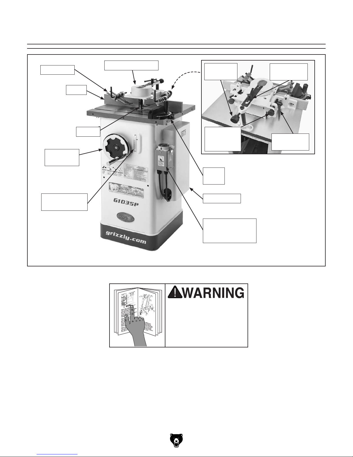
Components & Terminology
Hold Down
Fence
Spindle
Elevation
Handwheel
Spindle Height
Scale
Safety Guard
Guard
Lock Knob
Fence
Adjustment
Knob
Figure 1. Rear view.
Miter
Gauge
Motor Cover
ON/OFF
Reversing Switch
w/Padlock
Guard Lock
Handle
Fence Lock
Handle
Figure 2. Model G1035P shown.
To reduce the risk of
serious injury when using
this machine, read and
understand this entire
manual before beginning
any operations.
Model G1035/G1035P (Mfg. Since 4/10)
-3-

MACHINE DATA
SHEET
Customer Service #: (570) 546-9663 · To Order Call: (800) 523-4777 · Fax #: (800) 438-5901
MODEL G1035/G1035P 1-1/2 HP SHAPER
Product Dimensions:
Weight.............................................................................................................................................................. 195 lbs.
Width (side-to-side) x Depth (front-to-back) x Height..................................................................... 22 x 25 x 40-1/2 in.
Footprint (Length x Width)............................................................................................................... 17-1/2 x 15-1/2 in.
Shipping Dimensions:
Type..................................................................................................................................................... Cardboard Box
Content........................................................................................................................................................... Machine
Weight.............................................................................................................................................................. 221 lbs.
Length x Width x Height....................................................................................................................... 24 x 24 x 42 in.
Must Ship Upright................................................................................................................................................... Yes
Electrical:
Power Requirement............................................................................................. 120V or 240V, Single-Phase, 60 Hz
Prewired Voltage.................................................................................................................................................. 120V
Full-Load Current Rating....................................................................................................... 12A at 120V, 6A at 240V
Minimum Circuit Size.......................................................................................................... 15A at 120V, 15A at 240V
Connection Type....................................................................................................................................... Cord & Plug
Power Cord Included.............................................................................................................................................. Yes
Power Cord Length................................................................................................................................................. 6 ft.
Power Cord Gauge......................................................................................................................................... 14 AWG
Plug Included.......................................................................................................................................................... Yes
Included Plug Type................................................................................................................................. 5-15 for 120V
Recommended Plug Type...................................................................................................................... 6-15 for 240V
Switch Type....................................................................................................................... Lockable Forward/Reverse
MODEL G1035 1‐1/2 HP SHAPER
Motors:
Main
Horsepower............................................................................................................................................. 1.5 HP
Phase............................................................................................................................................ Single-Phase
Amps....................................................................................................................................................... 12A/6A
Speed................................................................................................................................................ 3450 RPM
Type................................................................................................................. TEFC Capacitor-Start Induction
Power Transfer .................................................................................................................................. Belt Drive
Bearings..................................................................................................... Shielded & Permanently Lubricated
Main Specifications:
Operation Info
Max. Cutter Height................................................................................................................................. 2-1/2 in.
Max. Cutter Diameter................................................................................................................................... 5 in.
Spindle Sizes..................................................................................................................................... 1/2, 3/4 in.
Spindle Lengths........................................................................................................................... 2-3/4, 3-1/2 in.
Exposed Spindle Length........................................................................................................................ 3-1/8 in.
Spindle Cap. Under the Nut............................................................................................................... 2, 2-1/2 in.
Spindle Speeds.................................................................................................................... 7000, 10,000 RPM
Spindle Travel.............................................................................................................................................. 3 in.
Spindle Openings.................................................................................................................... 1-1/4, 3-1/2, 5 in.
-4-
Model G1035/G1035P (Mfg. Since 4/10)

Table Info
Number of Table Inserts................................................................................................................................... 2
Table Insert Sizes I.D.................................................................................................................. 1-1/4, 3-1/2 in.
Table Insert Sizes O.D...................................................................................................................... 3-1/2, 5 in.
Table Counterbore Diameter....................................................................................................................... 5 in.
Table Counterbore Depth....................................................................................................................... 7/16 in.
Table Size Length................................................................................................................................ 20-1/4 in.
Table Size Width........................................................................................................................................ 18 in.
Table Size Thickness............................................................................................................................ 1-1/4 in.
Floor to Table Height........................................................................................................................... 33-1/2 in.
Table Fence Length............................................................................................................................. 21-1/2 in.
Table Fence Width.................................................................................................................................... 1/2 in.
Table Fence Height............................................................................................................................... 2-3/4 in.
Miter Gauge Info
Miter Angle................................................................................................................................. 0 – 60 deg. L/R
Miter Gauge Slot Type.................................................................................................................... Straight Slot
Miter Gauge Slot Width............................................................................................................................. 3/4 in.
Miter Gauge Slot Height........................................................................................................................... 3/8 in.
Construction
Table....................................................................................................................... Precision-Ground Cast Iron
Body Assembly.................................................................................................................................... Cast Iron
Cabinet.......................................................................................................................................... Formed Steel
Fence................................................................................................................................. Cast Iron with Wood
Miter Gauge......................................................................................................................................... Cast Iron
Guard................................................................................................................................................... Cast Iron
Spindle Bearings........................................................................................ Shielded & Permanently Lubricated
Paint Type/Finish....................................................................................................................... Powder Coated
Other
Mobile Base........................................................................................................................................... D2260A
Other Specifications:
Country of Origin .............................................................................................................................................. Taiwan
Warranty ........................................................................................................................................................... 1 Year
Approximate Assembly & Setup Time ........................................................................................................ 30 Minutes
Serial Number Location ................................................................................................... ID Label on Center of Stand
ISO 9001 Factory .................................................................................................................................................... No
Certified by a Nationally Recognized Testing Laboratory (NRTL) ......................................................................... Yes
Features:
Cast-Iron Miter Gauge & Starting Pins
Precision-Ground Cast-Iron Table
Green Powder Coated Paint on Cabinet
Independently Adjustable Cast-Iron Fence with Wood Facing
Precision Wheel Adjustment
Two Spindle Speeds
Sealed Ball Bearing Movement
Interchangeable Spindles
Hold Down Springs
Steel Cabinet Type Stand
Vertical Spindle Lock
Model G1035/G1035P (Mfg. Since 4/10)
-5-

SECTION 1: SAFETY
For Your Own Safety, Read Instruction
Manual Before Operating This Machine
The purpose of safety symbols is to attract your attention to possible hazardous conditions.
This manual uses a series of symbols and signal words intended to convey the level of importance of the safety messages. The progression of symbols is described below. Remember that
safety messages by themselves do not eliminate danger and are not a substitute for proper
accident prevention measures. Always use common sense and good judgment.
Indicates an imminently hazardous situation which, if not avoided,
WILL result in death or serious injury.
Indicates a potentially hazardous situation which, if not avoided,
COULD result in death or serious injury.
Indicates a potentially hazardous situation which, if not avoided,
MAY result in minor or moderate injury. It may also be used to alert
against unsafe practices.
This symbol is used to alert the user to useful information about
NOTICE
proper operation of the machine.
Safety Instructions for Machinery
OWNER’S MANUAL. Read and understand this
owner’s manual BEFORE using machine.
TRAINED OPERATORS ONLY. Untrained operators have a higher risk of being hurt or killed.
Only allow trained/supervised people to use this
machine. When machine is not being used, disconnect power, remove switch keys, or lock-out
machine to prevent unauthorized use—especially
around children. Make your workshop kid proof!
DANGEROUS ENVIRONMENTS. Do not use
machinery in areas that are wet, cluttered, or have
poor lighting. Operating machinery in these areas
greatly increases the risk of accidents and injury.
MENTAL ALERTNESS REQUIRED. Full mental
alertness is required for safe operation of machinery. Never operate under the influence of drugs or
alcohol, when tired, or when distracted.
ELECTRICAL EQUIPMENT INJURY RISKS. You
can be shocked, burned, or killed by touching live
electrical components or improperly grounded
machinery. To reduce this risk, only allow qualified
service personnel to do electrical installation or
repair work, and always disconnect power before
accessing or exposing electrical equipment.
DISCONNECT POWER FIRST.
nect machine from power supply BEFORE making
adjustments, changing tooling, or servicing machine.
This prevents an injury risk from unintended startup
or contact with live electrical components.
EYE PROTECTION. Always wear ANSI-approved
safety glasses or a face shield when operating or
observing machinery to reduce the risk of eye
injury or blindness from flying particles. Everyday
eyeglasses are NOT approved safety glasses.
Always discon-
-6-
Model G1035/G1035P (Mfg. Since 4/10)

WEARING PROPER APPAREL. Do not wear
clothing, apparel or jewelry that can become
entangled in moving parts. Always tie back or
cover long hair. Wear non-slip footwear to reduce
risk of slipping and losing control or accidentally
contacting cutting tool or moving parts.
HAZARDOUS DUST. Dust created by machinery
operations may cause cancer, birth defects, or
long-term respiratory damage. Be aware of dust
hazards associated with each workpiece material. Always wear a NIOSH-approved respirator to
reduce your risk.
HEARING PROTECTION. Always wear hearing protection when operating or observing loud
machinery. Extended exposure to this noise
without hearing protection can cause permanent
hearing loss.
REMOVE ADJUSTING TOOLS. Tools left on
machinery can become dangerous projectiles
upon startup. Never leave chuck keys, wrenches,
or any other tools on machine. Always verify
removal before starting!
USE CORRECT TOOL FOR THE JOB. Only use
this tool for its intended purpose—do not force
it or an attachment to do a job for which it was
not designed. Never make unapproved modifications—modifying tool or using it differently than
intended may result in malfunction or mechanical
failure that can lead to personal injury or death!
AWKWARD POSITIONS. Keep proper footing
and balance at all times when operating machine.
Do not overreach! Avoid awkward hand positions
that make workpiece control difficult or increase
the risk of accidental injury.
CHILDREN & BYSTANDERS. Keep children and
bystanders at a safe distance from the work area.
Stop using machine if they become a distraction.
GUARDS & COVERS. Guards and covers reduce
accidental contact with moving parts or flying
debris. Make sure they are properly installed,
undamaged, and working correctly BEFORE
operating machine.
FORCING MACHINERY. Do not force machine.
It will do the job safer and better at the rate for
which it was designed.
NEVER STAND ON MACHINE. Serious injury
may occur if machine is tipped or if the cutting
tool is unintentionally contacted.
STABLE MACHINE. Unexpected movement during operation greatly increases risk of injury or
loss of control. Before starting, verify machine is
stable and mobile base (if used) is locked.
USE RECOMMENDED ACCESSORIES. Consult
this owner’s manual or the manufacturer for recommended accessories. Using improper accessories will increase the risk of serious injury.
UNATTENDED OPERATION. To reduce the
risk of accidental injury, turn machine OFF and
ensure all moving parts completely stop before
walking away. Never leave machine running
while unattended.
MAINTAIN WITH CARE. Follow all maintenance
instructions and lubrication schedules to keep
machine in good working condition. A machine
that is improperly maintained could malfunction,
leading to serious personal injury or death.
DAMAGED PARTS. Regularly inspect machine
for damaged, loose, or mis-adjusted parts—or
any condition that could affect safe operation.
Immediately repair/replace BEFORE operating
machine. For your own safety, DO NOT operate
machine with damaged parts!
MAINTAIN POWER CORDS. When disconnecting cord-connected machines from power, grab
and pull the plug—NOT the cord. Pulling the cord
may damage the wires inside. Do not handle
cord/plug with wet hands. Avoid cord damage by
keeping it away from heated surfaces, high traffic
areas, harsh chemicals, and wet/damp locations.
EXPERIENCING DIFFICULTIES. If at any time
you experience difficulties performing the intended operation, stop using the machine! Contact our
Technical Support at (570) 546-9663.
Model G1035/G1035P (Mfg. Since 4/10)
-7-

Additional Safety for Shapers
GUARDING FROM CUTTER EXPOSURE: When
setting up cuts, take every possible step to reduce
operator exposure to the cutter to prevent laceration or amputation injuries. These steps include
but are not limited to: Keeping the unused portion
of the cutter below the table, using the smallest
table insert allowed by cutter, adjusting fences
as close as practical to the cutter on both sides,
using a properly installed box guard, and securing the guard as close to the workpiece as possible. Keep the provided guard or other protective
devices between your hands and the cutter at all
times!
KEEPING HANDS SAFE: Never pass your hands
near or directly over or in front of the cutter. As
one hand approaches the 6-inch radius point,
move it in an arc motion away from the cutter to
the outfeed side and reposition that hand more
than 6 inches beyond the cutter. Do not use awkward hand positions.
SMALL WORKPIECES: There is a risk when
shaping a small workpiece that it will slip between
the fence boards and draw the operator's hand
into the spinning cutter. Keep fingers away from
revolving cutter—use fixtures when necessary.
Where practical, shape longer stock and cut to
size.
TESTING FOR CLEARANCE: If the spinning
cutter should contact the fence, guard, or insert,
the resulting flying debris presents injury hazards.
Unplug the shaper, and always rotate the spindle
by hand to test any new setup for proper cutter
clearance before starting the shaper.
SAFE CUTTER INSTALLATION: A tight spindle
nut reduces the risk of the cutter or rub collars
flying off during operation. Always make sure that
the quill key and the spindle keyway are aligned.
Always use both spindle nuts and make sure they
are tight.
CUTTER POSITIONING: Keep the cutters on the
underside of the workpiece whenever possible to
reduce operator exposure to the moving cutter.
AVOIDING CUTTER AND WORKPIECE GRAB:
Moving the workpiece into the cutter in the same
direction as it is rotating will aggressively pull
the workpiece from your hands and could draw
them into the cutter. Always make sure the cutter
is rotating in the correct direction before starting
shaper, and always feed the workpiece against
the rotation of the cutter.
PREPARING A WORKPIECE: Always "square
up" a workpiece before you run it through the
shaper. A warped workpiece is difficult to process
and increases the risk of an accident. Always
inspect the workpiece before shaping. The danger of kickback is increased when the stock has
knots, holes, or foreign objects in it.
AVOIDING AN OVERLOAD: Removing too much
material in one pass increases the risk of the
workpiece kicking back toward the operator.
Never attempt to remove too much material in
one pass. Several light passes are safer and give
a cleaner finish.
SAFELY FEEDING A WORKPIECE: We recommend using some type of fixture, jig, or hold-down
device to safely support the workpiece when
feeding. ALWAYS use a push stick when shaping small or narrow workpieces. Use an outfeed
support table if shaping long workpieces to make
sure that they remain supported during the entire
cutting procedure.
SAFETY GUARDS. To reduce the risk of unintentional contact with the rotating cutter, ALWAYS
make sure the cutter safety guard and a properly dimensioned box guard are correctly installed
before beginning operation.
CONTOUR SHAPING: When shaping contoured
work and using a rub collar, NEVER start shaping at a corner. See the rub collar section in the
manual. Use the overhead safety guard when the
adjustable fence is not in place.
-8-
Model G1035/G1035P (Mfg. Since 4/10)

SECTION 2: POWER SUPPLY
Before installing the machine, consider the availability and proximity of the required power supply
circuit. If an existing circuit does not meet the
requirements for this machine, a new circuit must
be installed. To minimize the risk of electrocution,
fire, or equipment damage, installation work and
electrical wiring must be done by an electrician or
qualified service personnel in accordance with all
applicable codes and standards.
or equipment damage
may occur if machine is
not properly grounded
and connected to power
The full-load current rating is the amperage a
machine draws at 100% of the rated output power.
On machines with multiple motors, this is the
amperage drawn by the largest motor or sum of all
motors and electrical devices that might operate
at one time during normal operations.
The full-load current is not the maximum amount
of amps that the machine will draw. If the machine
is overloaded, it will draw additional amps beyond
the full-load rating.
If the machine is overloaded for a sufficient length
of time, damage, overheating, or fire may result—
especially if connected to an undersized circuit.
To reduce the risk of these hazards, avoid overloading the machine during operation and make
sure it is connected to a power supply circuit that
meets the specified circuit requirements.
For your own safety and protection of
Note: Circuit requirements in this manual apply to
a dedicated circuit—where only one machine will
be running on the circuit at a time. If machine will
be connected to a shared circuit where multiple
machines may be running at the same time, consult an electrician or qualified service personnel to
ensure circuit is properly sized for safe operation.
A power supply circuit includes all electrical
equipment between the breaker box or fuse panel
in the building and the machine. The power supply circuit used for this machine must be sized to
safely handle the full-load current drawn from the
machine for an extended period of time. (If this
machine is connected to a circuit protected by
fuses, use a time delay fuse marked D.)
This machine is prewired to operate on a power
supply circuit that has a verified ground and meets
the following requirements:
This machine can be converted to operate on a
power supply circuit that has a verified ground
and meets the requirements listed below. (Refer
to Voltage Conversion instructions for details.)
Availability
Electrocution, fire, shock,
supply.
Full-Load Current Rating
Circuit Information
property, consult an electrician if you are
unsure about wiring practices or electrical
codes in your area.
Full-Load Current Rating at 120V ..... 12 Amps
Full-Load Current Rating at 240V ....... 6 Amps
Model G1035/G1035P (Mfg. Since 4/10)
Circuit Requirements for 120V
Nominal Voltage ........................................120V
Cycle .......................................................... 60 Hz
Phase ........................................... Single-Phase
Circuit Rating ...................................... 15 Amps
Plug/Receptacle ............................. NEMA 5-15
Circuit Requirements for 240V
Nominal Voltage ........................................240V
Cycle .......................................................... 60 Hz
Phase ........................................... Single-Phase
Circuit Rating ...................................... 15 Amps
Plug/Receptacle ............................. NEMA 6 -15
-9-

Improper connection of the equipment-grounding
wire can result in a risk of electric shock. The
wire with green insulation (with or without yellow
stripes) is the equipment-grounding wire. If repair
or replacement of the power cord or plug is necessary, do not connect the equipment-grounding
wire to a live (current carrying) terminal.
Check with a qualified electrician or service personnel if you do not understand these grounding
requirements, or if you are in doubt about whether
the tool is properly grounded. If you ever notice
that a cord or plug is damaged or worn, disconnect it from power, and immediately replace it with
a new one.
We do not recommend using an extension cord
with this machine.
cord, only use it if absolutely necessary and only
on a temporary basis.
Extension cords cause voltage drop, which can
damage electrical components and shorten motor
life. Voltage drop increases as the extension cord
size gets longer and the gauge size gets smaller
(higher gauge numbers indicate smaller sizes).
Any extension cord used with this machine must
be in good condition and contain a ground wire
and matching plug/receptacle. Additionally, it must
meet the following size requirements:
Grounding Requirements
This machine MUST be grounded. In the event
of certain malfunctions or breakdowns, grounding
reduces the risk of electric shock by providing a
path of least resistance for electric current.
process. DO NOT connect to power until
For 120V operation: This machine is equipped
with a power cord that has an equipment-grounding wire and a grounding plug (see following figure). The plug must only be inserted into a matching receptacle (outlet) that is properly installed
and grounded in accordance with all local codes
and ordinances.
For 240V operation: The plug specified under
“
page has a grounding prong that must be attached
to the equipment-grounding wire on the included
power cord. The plug must only be inserted into
a matching receptacle (see following figure) that
is properly installed and grounded in accordance
with all local codes and ordinances.
GROUNDED
5-15 RECEPTACLE
Grounding Prong
5-15 PLUG
Serious injury could occur if you connect
machine to power before completing setup
instructed later in this manual.
Neutral Hot
Figure 3. Typical 5-15 plug and receptacle.
Circuit Requirements for 240V” on the previous
GROUNDED
6-15 RECEPTACLE
Current Carrying Prongs
Figure 4. Typical 6-15 plug and receptacle.
-10 -
Grounding Prong
6-15 PLUG
Extension Cords
If you must use an extension
Minimum Gauge Size ...........................14 AWG
Maximum Length (Shorter is Better).......50 ft.
Model G1035/G1035P (Mfg. Since 4/10)
Voltage Conversion
The voltage conversion MUST be performed by
an electrician or a qualified service personnel.
The voltage conversion procedure consists of
rewiring the motor and installing the correct plug.
A wiring diagram is provided on Page 49 for your
reference.
IMPORTANT: If the diagram included on the
motor conflicts with the one on Page 49, the motor
may have changed since the manual was printed.
Use the diagram included on the motor junction
box cover instead.
Items Needed Qty
• Phillips Head Screwdriver #2 ..................... 1
• Electrical Tap e ............................ As Needed
• Wire Nut (14 AWG x 1) ............................... 1
• Plug 6-15 .................................................... 1
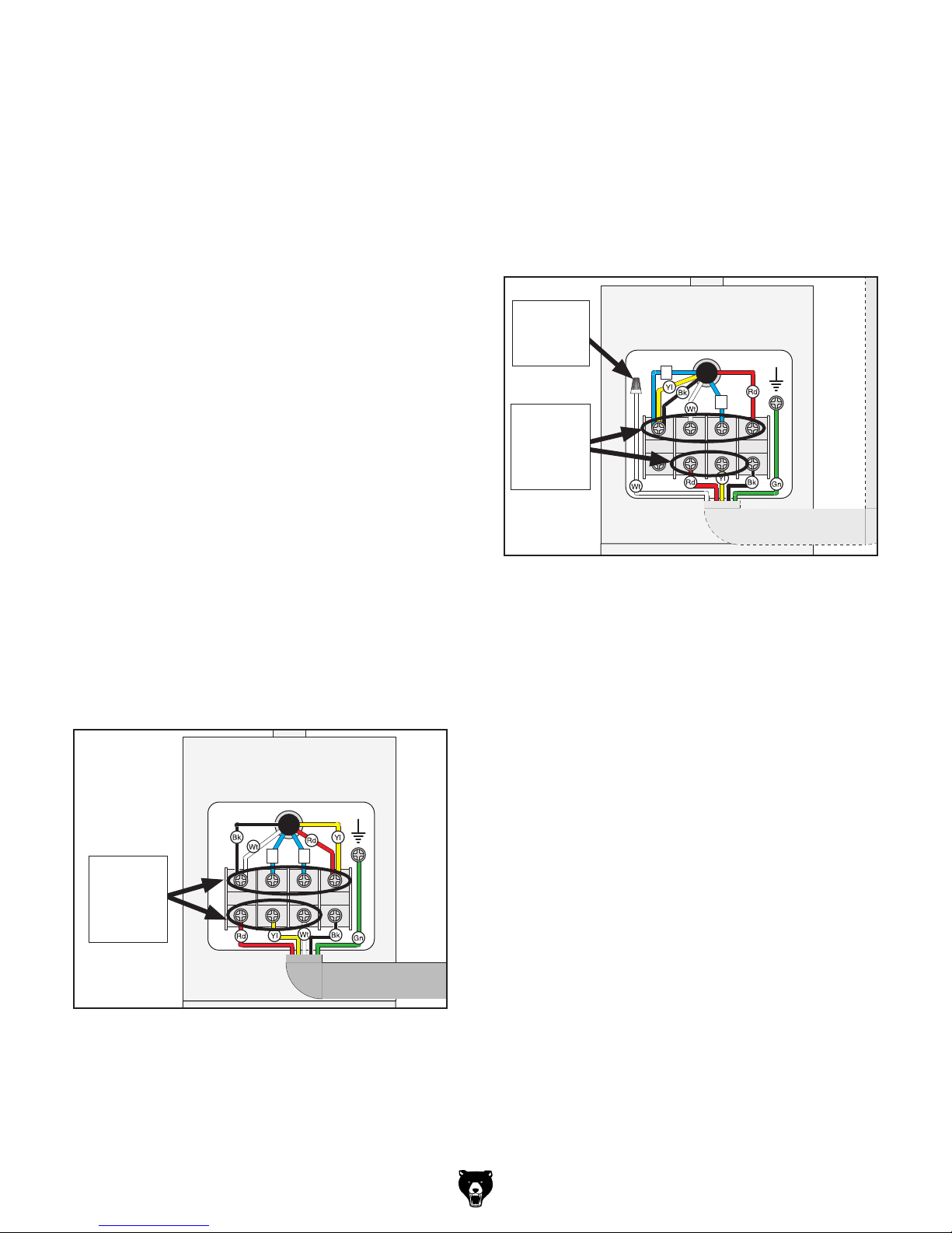
To convert the Model G1035/G1035P to 240V:
4. Connect the motor wires, as shown in Figure
6.
5. Connect the white wire from the #6 terminal
on the switch with a wire nut. Once snug,
wrap electrical tape around the wire nut and
the connected wire, to reduce the likelihood
of the wire nut vibrating loose during motor
operation.
Wire Nut
240V Motor
on White
Wire
5
6
Gnd
Tighten
These
Terminal
Screws
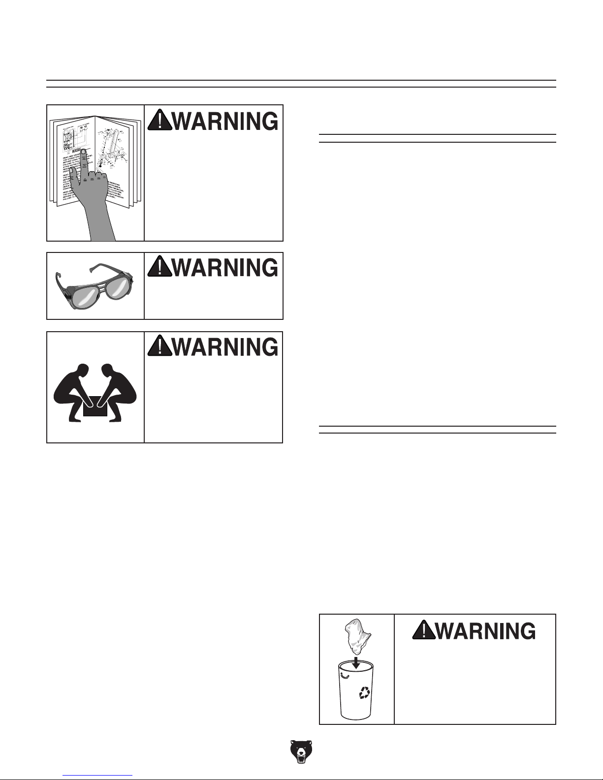
1. DISCONNECT SHAPER FROM POWER!
2. Cut off the included plug.
3. Open the motor junction box, then loosen
the terminal screws indicated in Figure 5.
Remove the wires connected to those terminals.
120V Single-Phase
Motor (Pre-Wired)
Gnd
6
Loosen
These
Terminal
Screws
5
Figure 6. Motor rewired for 240V.
6. Close and secure the motor junction box.
7. Install a 6-15 plug on the end of the cord,
according to the instructions and wiring diagrams provided by the plug manufacturer.
—If the plug manufacturer did not include
instructions, the wiring of a generic NEMA
6-15 plug is illustrated in the Wiring section on Page 49.
Figure 5. Locations to loosen terminal screws.
Model G1035/G1035P (Mfg. Since 4/10)
-11-
SECTION 3: SETUP
This machine was carefully packaged for safe
transport. When unpacking, separate all enclosed
items from packaging materials and inspect them
for shipping damage.
,
please
IMPORTANT:
you are completely satisfied with the machine and
have resolved any issues between Grizzly or the
shipping agent. You MUST have the original pack-
aging to file a freight claim. It is also extremely
helpful if you need to return your machine later.
Needed for Setup
This machine presents
serious injury hazards
to untrained users. Read
through this entire manual to become familiar with
the controls and operations before starting the
machine!
Wear safety glasses during the entire setup process!
This machine and its components are very heavy.
Get lifting help or use
power lifting equipment
such as a forklift to move
heavy items.
The following are needed to complete the setup
process, but are not included with your machine.
Description Qty
• Additional Person ....................................... 1
• Safety Glasses ........................................... 1
• Cleaner/Degreaser (Page 38) .... As Needed
• Disposable Shop Rags ............... As Needed
• Forklift ......................................................... 1
• Straightedge 12" or longer ......................... 1
• Open End Wrench 10mm ........................... 1
• Hex Wrench 3, 4, 8mm .....................1 Each
• Screwdriver Phillips #2 ............................... 1
• Screwdriver Flat Head #2 ........................... 1
• Dust Collection System (Optional) ............. 1
• Dust Hose 3" (Optional) ............................. 1
• Hose Clamps 3" (Optional) ......................... 2
Unpacking
-12-
If items are damaged
call us immediately at (570) 546-9663.
Save all packaging materials until
SUFFOCATION HAZARD!
Immediately discard all plastic bags and packing materials to eliminate choking/suffocation hazards for children
and animals.
Model G1035/G1035P (Mfg. Since 4/10)
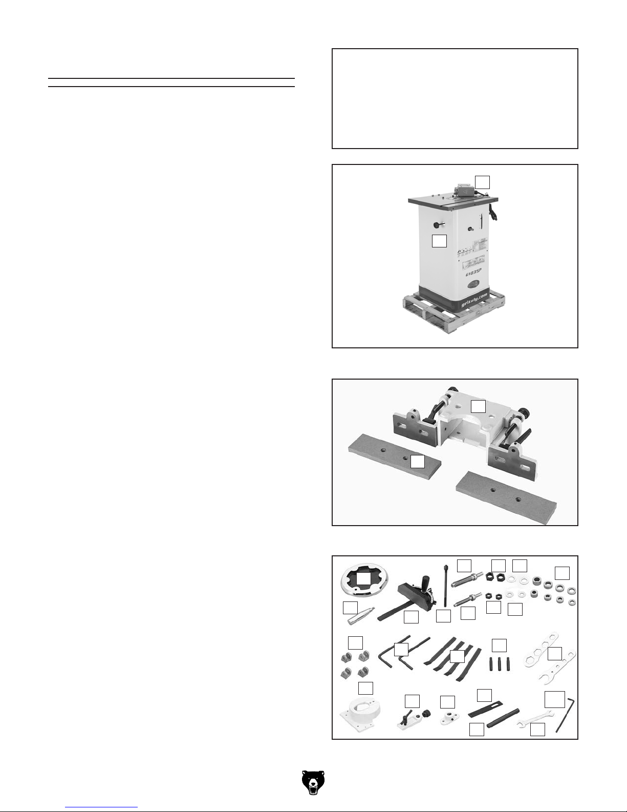
Inventory
The following is a list of items shipped with your
machine. Before beginning setup, lay these items
out and inventory them.
If any non-proprietary parts are missing (e.g. a
nut or a washer), we will gladly replace them; or
for the sake of expediency, replacements can be
obtained at your local hardware store.
Box 1: (Figure 7) Qty
A. Shaper Unit ................................................ 1
B. FWD/REV Switch ....................................... 1
Box 2: (Figure 8) Qty
C. Fence Assembly ......................................... 1
D. Fence Faces ............................................... 2
Box 3 (Figure 9):
E. Handwheel ................................................. 1
F. Handle for Handwheel ............................... 1
G. Miter Gauge ............................................... 1
H. Drawbar & Nut ............................................ 1
I. Spindle
J. Spindle Nuts
K. Spindle Washers
L. Spindle
M. Spindle Nuts
N. Spindle Washers
O. Spacer Set .................................................. 8
P. Spindle Wrench Set.................................... 2
Q. Starting Pins .............................................. 3
R. Hold-Downs ................................................ 4
S. Hold Down Bars ......................................... 2
T. Hold Down Brackets .................................. 4
U. Safety Guard .............................................. 1
V. Extension Bracket ...................................... 1
W. Shaft Mount Bracket ................................... 1
X. Extension Bar ............................................. 1
Y. Safety Guard Shaft .................................... 1
Z. Open-End Wrench 12 x 14 ......................... 1
AA. Hex Wrench 5mm ....................................... 1
AB. Hardware Bag (Not Shown) ........................ 1
—Set Screws
—Hex Nuts
—Flat Head Screws
—Flat Washers
—Flat Head Screws
—Hex Nuts
Model G1035/G1035P (Mfg. Since 4/10)
1
⁄2 " .................................................. 1
1
⁄2 " ......................................... 2
1
3
⁄4" .................................................. 1
⁄2 " ................................... 2
3
⁄4".......................................... 2
3
⁄4" ................................... 2
1
⁄4"-20 x 3⁄8"........................... 4
1
⁄4"-20 ...................................... 2
5
⁄16" .......................................... 4
1
⁄4"-20 x 5⁄8" ................ 2
5
⁄16" .................................... 4
5
⁄16"-18 x 11⁄2 " .............. 4
NOTICE
If you cannot find an item on this list, carefully check around/inside the machine and
packaging materials. Often, these items get
lost in packaging materials while unpacking or they are pre-installed at the factory.
B
A
Figure 7. Box 1 inventory.
C
D
Figure 8. Box 2 inventory.
L M N
E
F
G
T
S
H
R
U
V
W
J
I
K
Q
X
Y Z
Figure 9. Box 3 inventory.
O
P
AA
-13-
The unpainted surfaces of your machine are
coated with a heavy-duty rust preventative that
prevents corrosion during shipment and storage.
This rust preventative works extremely well, but it
will take a little time to clean.
Be patient and do a thorough job cleaning your
machine. The time you spend doing this now will
give you a better appreciation for the proper care
of your machine's unpainted surfaces.
There are many ways to remove this rust preventative, but the following steps work well in a wide
variety of situations. Always follow the manufacturer’s instructions with any cleaning product you
use and make sure you work in a well-ventilated
area to minimize exposure to toxic fumes.
Before cleaning, gather the following:
• Disposable rags
• Cleaner/degreaser (WD•40 works well)
• Safety glasses & disposable gloves
• Plastic paint scraper (optional)
Basic steps for removing rust preventative:
1.
2.
3.
4.
Many cleaning solvents
work in a well-ventilated
Avoid chlorine-based solvents, such as
Cleanup
Gasoline and petroleum
products have low flash
points and can explode
or cause fire if used to
clean machinery. A v oi d
using these products
to clean machinery.
Put on safety glasses.
Coat the rust preventative with a liberal
amount of cleaner/degreaser, then let it soak
for 5–10 minutes.
Wipe off the surfaces. If your cleaner/degreas-
er is effective, the rust preventative will wipe
off easily. If you have a plastic paint scraper,
scrape off as much as you can first, then wipe
off the rest with the rag.
are toxic if inhaled. Only
area.
NOTICE
acetone or brake parts cleaner, that may
damage painted surfaces.
Repeat Steps 2–3 as necessary until clean,
then coat all unpainted surfaces with a quality
metal protectant to prevent rust.
-14-
Model G1035/G1035P (Mfg. Since 4/10)
Site Considerations
Weight Load
Refer to the
of your machine. Make sure that the surface upon
which the machine is placed will bear the weight
of the machine, additional equipment that may be
installed on the machine, and the heaviest workpiece that will be used. Additionally, consider the
weight of the operator and any dynamic loading
that may occur when operating the machine.
Space Allocation
Consider the largest size of workpiece that will
be processed through this machine and provide
enough space around the machine for adequate
operator material handling or the installation of
auxiliary equipment. With permanent installations,
leave enough space around the machine to open
or remove doors/covers as required by the maintenance and service described in this manual.
See below for required space allocation.
Physical Environment
Extreme conditions for this type of machinery are
Place this machine near an existing power source.
other hazards. Make sure to leave enough space
Shadows, glare, or strobe effects that may distract
Machine Data Sheet for the weight
Children or untrained people
may be seriously injured by
this machine. Only install in an
access restricted location.
The physical environment where the machine is
operated is important for safe operation and longevity of machine components. For best results,
operate this machine in a dry environment that is
free from excessive moisture, hazardous chemicals, airborne abrasives, or extreme conditions.
generally those where the ambient temperature
range exceeds 41°–104°F; the relative humidity
range exceeds 20%–95% (non-condensing); or
the environment is subject to vibration, shocks,
or bumps.
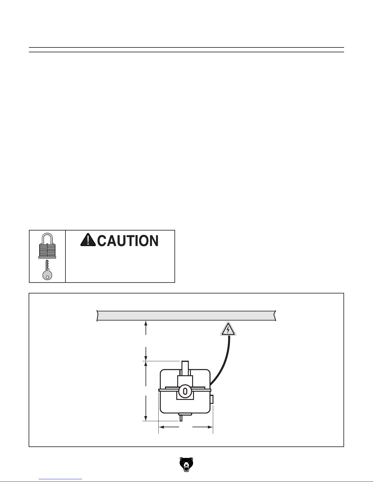
Electrical Installation
Make sure all power cords are protected from
traffic, material handling, moisture, chemicals, or
around machine to disconnect power supply or
apply a lockout/tagout device, if required.
Lighting
Lighting around the machine must be adequate
enough that operations can be performed safely.
or impede the operator must be eliminated.
Wall
Model G1035/G1035P (Mfg. Since 4/10)
Minimum 30"
25"
Figure 10. Minimum working clearances.
22"
-15-
Assembly
Most of your Model G1035/G1035P has been
assembled at the factory, but some parts must be
assembled or installed after delivery.
The Model G1035/G1035P is equipped with
motor braces to prevent damage to the motor
during shipping. These braces are intended to be
removed before operation.
To assemble the shaper:
1. Remove the motor cover and rear cover from
the shaper cabinet by removing screws that
hold them in place.
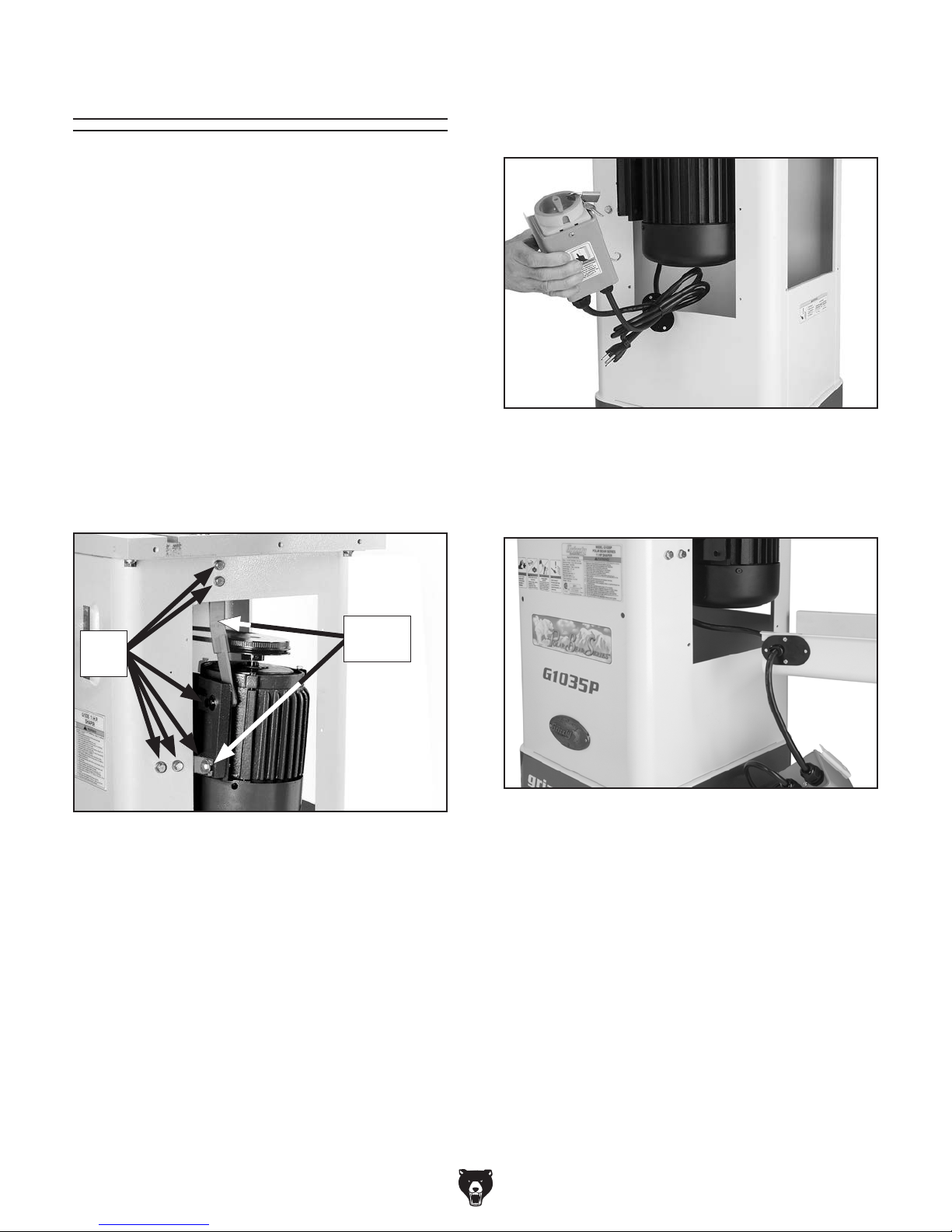
3. Remove the power switch cords, the FWD/
REV switch and grommet through the motor
cover opening, as shown in Figure 12.
Figure 12. Removing switch from cabinet.
2. Using a 12mm wrench, remove the six hex
bolts, hex nuts and flat washers and the two
motor braces shown in Figure 11.
Hex
Bolts
Figure 11. Motor braces and hex bolts.
Motor
Braces
4. Install the grommet plate, as shown in Figure
13, using the screws and nuts already mount-
ed on the motor cover.
Figure 13. Installing grommet.
5. Re-install the two hex bolts and washers
removed in Step 2 onto the motor.
6. Re-install the motor cover.
-16 -
7. Remove the shipping notice tag from the cabinet so you can mount the FWD/REV switch
in the next step.
Model G1035/G1035P (Mfg. Since 4/10)

8. Mount the FWD/REV switch to the cabinet, as
shown in Figure 14, using the screws already
mounted in the cabinet at that location.
Figure 14. Mounting switch to cabinet.
9. Re-install the remaining fasteners removed in
Step 2.
10. Re-install the rear cover.
11. Slide the handwheel onto the handwheel
shaft shown in Figure 15.
Handwheel
Shaft
Figure 15. Location of handwheel shaft.
12. Tighten the handwheel set screw against the
flat part of the handwheel shaft.
13. Thread the handle into the handwheel, and
tighten the nut on the handle against the
handwheel.
Model G1035/G1035P (Mfg. Since 4/10)
-17-
Spindle
The Model G1035/G1035P comes with 1⁄2" & 3⁄4"
spindles. Each spindle is sized to work efficiently
with cutters and spacers that have
bores. The spindles must be inserted correctly
and remain stationary in order to produce quality work. When installing and changing spindles,
make sure the spindle seats snugly and that there
is enough drawbar threaded into the bottom of the
spindle to safely secure it in place.
Incorrect assembly can allow the spindle
and cutter to fly off the machine, which
could cause injury or death. Make certain
the spindle is properly assembled before
operating the shaper. If you are uncertain of
any aspect of this assembly, please review
these instructions again or contact our
Technical Support.
To install a spindle:
1. Remove the hex nuts from the spindle.
1
⁄2" or 3⁄4"
3. Place the spindle/drawbar into the spindle
cartridge at the top of the table. Line up the
keyway on the spindle with the locating pin at
the top of the spindle cartridge (see Figure
17). You will feel the spindle seat itself.
Keyway
Spindle
Cartridge
Pin
Figure 17. Dropping the spindle into place.
Make sure the spindle keyway and pin are
aligned and properly seated before tightening the drawbar nut. Improper assembly can
create an unsafe condition and possible
injury to the operator.
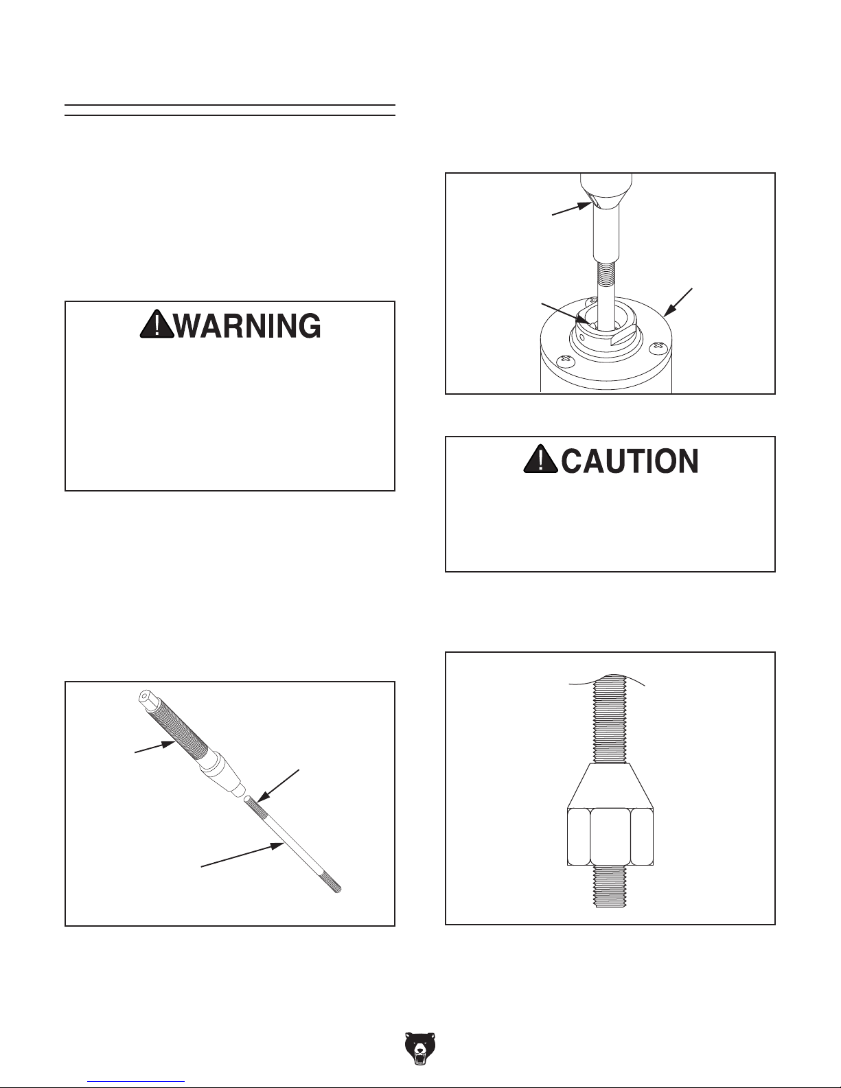
2. Thread the drawbar approximately 10-15
turns into the bottom of the spindle. The
drawbar has two threaded ends. One of them
remains exposed (see Figure 16).
Spindle
Drawbar
Figure 16. Spindle and drawbar.
Short Threaded
End
4. Thread the drawbar nut, tapered side up, onto
the bottom of the drawbar (see Figure 18).
Figure 18. Nut threaded onto drawbar.
-18-
Model G1035/G1035P (Mfg. Since 4/10)
 Loading...