

Page 1

20'' PLANER
MODEL G1033
INSTRUCTION MANUAL
COPYRIGHT © 1990 BY GRIZZLY INDUSTRIAL, INC.
WARNING: NO PORTION OF THIS MANUAL MAY BE REPRODUCED IN ANY SHAPE
OR FORM WITHOUT THE WRITTEN APPROVAL OF GRIZZLY INDUSTRIAL, INC.
REVISED APRIL, 1999. PRINTED IN U.S.A.
Page 2

Page 3

G1033 20" Planer -1-
Table Of Contents
PAGE
1. SAFETY
SAFETY RULES FOR POWER TOOLS ..................................................................................2-3
ADDITIONAL SAFETY INSTRUCTIONS FOR PLANERS ..........................................................4
2. CIRCUIT REQUIREMENTS
220V OPERATION ......................................................................................................................5
FUSING ........................................................................................................................................5
GROUNDING................................................................................................................................5
EXTENSION CORDS ..................................................................................................................5
3. INTRODUCTION
COMMENTARY ............................................................................................................................6
UNPACKING ................................................................................................................................7
PARTS INVENTORY....................................................................................................................7
CLEAN UP....................................................................................................................................8
SITE CONSIDERATIONS ............................................................................................................8
4. ASSEMBLY
OVERVIEW ..................................................................................................................................9
EXTENSION ROLLERS ..............................................................................................................9
HANDWHEEL ..............................................................................................................................9
DUST HOOD ..............................................................................................................................10
SWITCH......................................................................................................................................10
KNIFE SETTING JIG ..................................................................................................................11
5. ADJUSTMENTS
CHAIN ADJUSTMENT................................................................................................................12
TABLE ADJUSTMENT ..............................................................................................................12
CHAIN DRIVE ............................................................................................................................13
BED ROLLERS ..........................................................................................................................14
KNIFE INSPECTION ..................................................................................................................15
KNIFE ADJUSTMENT ................................................................................................................15
FEED ROLLER SPEED..............................................................................................................16
ROLLER ADJUSTMENT ......................................................................................................16-17
SPRING TENSION ....................................................................................................................17
CHIP BREAKER ........................................................................................................................18
PRESSURE BAR........................................................................................................................18
CHIP DEFLECTOR ....................................................................................................................19
STATIC CHAIN ADJUSTER ......................................................................................................19
SCALE ADJUSTMENT ..............................................................................................................20
ANTI-KICKBACK FINGERS ......................................................................................................20
6. OPERATIONS
TEST RUN..................................................................................................................................21
OPERATIONAL TIPS ................................................................................................................21
WOOD CHARACTERISTICS ....................................................................................................22
7. MAINTENANCE
GENERAL ..................................................................................................................................23
KNIVES ......................................................................................................................................23
LUBRICATION............................................................................................................................24
BELT TENSION..........................................................................................................................25
BELT ALIGNMENT ....................................................................................................................25
8. CLOSURE
MACHINE DATA ........................................................................................................................27
TROUBLESHOOTING................................................................................................................28
PARTS BREAKDOWN AND PARTS LISTS ........................................................................29-35
ADJUSTMENT BLOCK PATTERN ............................................................................................36
WIRING DIAGRAM ....................................................................................................................37
WARRANTY AND RETURNS ....................................................................................................38
Page 4
-2- G1033 20" Planer
Safety Instructions For Power Tools
SECTION 1: SAFETY
5. KEEP CHILDREN AND VISITORS
AWAY. All children and visitors should be
kept a safe distance from work area.
6. MAKE WORK SHOP CHILD PROOF with
padlocks, master switches, or by removing
starter keys.
7. DON’T FORCE TOOL. It will do the job
better and safer at the rate for which it was
designed.
8. USE RIGHT TOOL. Don’t force tool or
attachment to do a job for which it was not
designed.
1. KEEP GUARDS IN PLACE and in working
order.
2. REMOVE ADJUSTING KEYS AND
WRENCHES. Form habit of checking to
see that keys and adjusting wrenches are
removed from tool before turning on.
3. KEEP WORK AREA CLEAN. Cluttered
areas and benches invite accidents.
4. DON’T USE IN DANGEROUS ENVIRONMENT. Don’t use power tools in damp or
wet locations, or where any flammable or
noxious fumes may exist. Keep work area
well lighted.
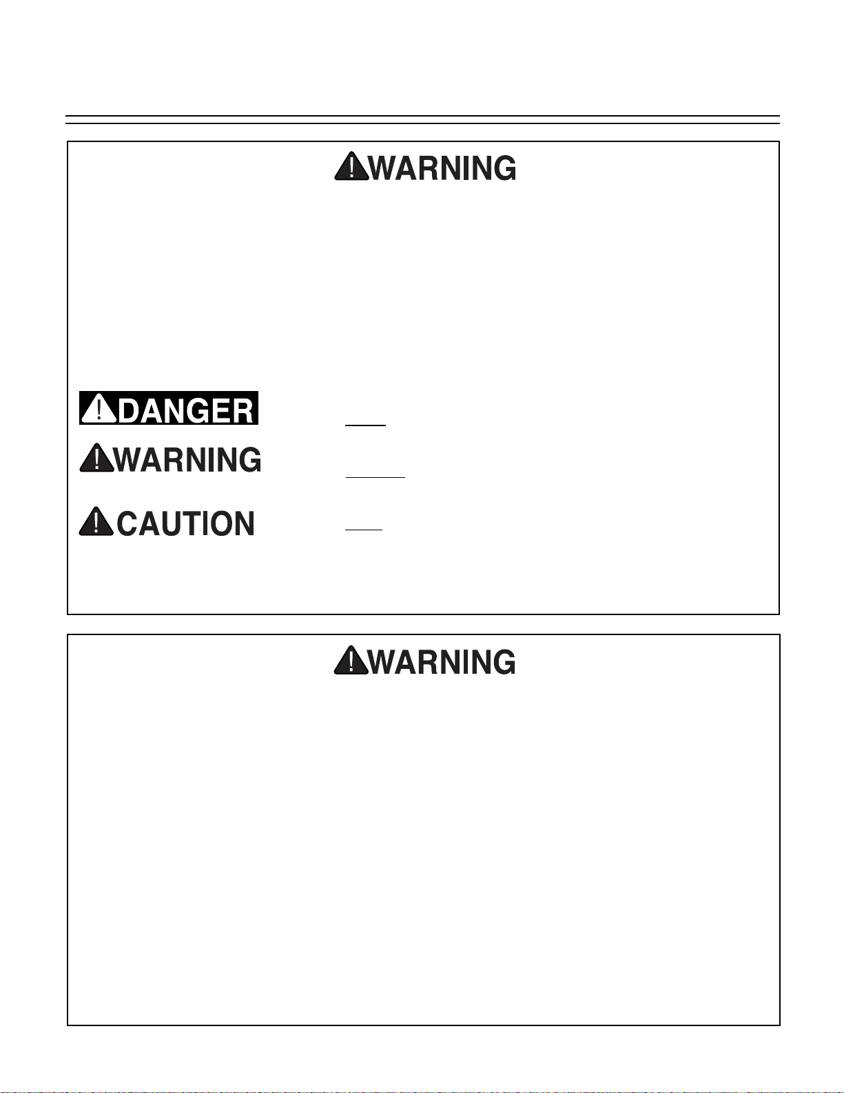
For Your Own Safety Read Instruction
Manual Before Operating This Equipment
Indicates an imminently hazardous situation which, if not
avoided, WILL result in death or serious injury.
Indicates a potentially hazardous situation which, if not
avoided, COULD
result in death or serious injury.
Indicates a potentially hazardous situation which, if not
avoided, MAY
result in minor or moderate injury. It may also
be used to alert against unsafe practices.
This symbol is used to alert the user to useful information
about proper operation of the equipment.
The purpose of safety symbols is to attract your attention to possible hazardous conditions.
This manual uses a series of symbols and signal words which are intended to convey the level
of importance of the safety messages. The progression of symbols is described below.
Remember that safety messages by themselves do not eliminate danger and are not a substitute for proper accident prevention measures.
NOTICE
Page 5
G1033 20" Planer -3-
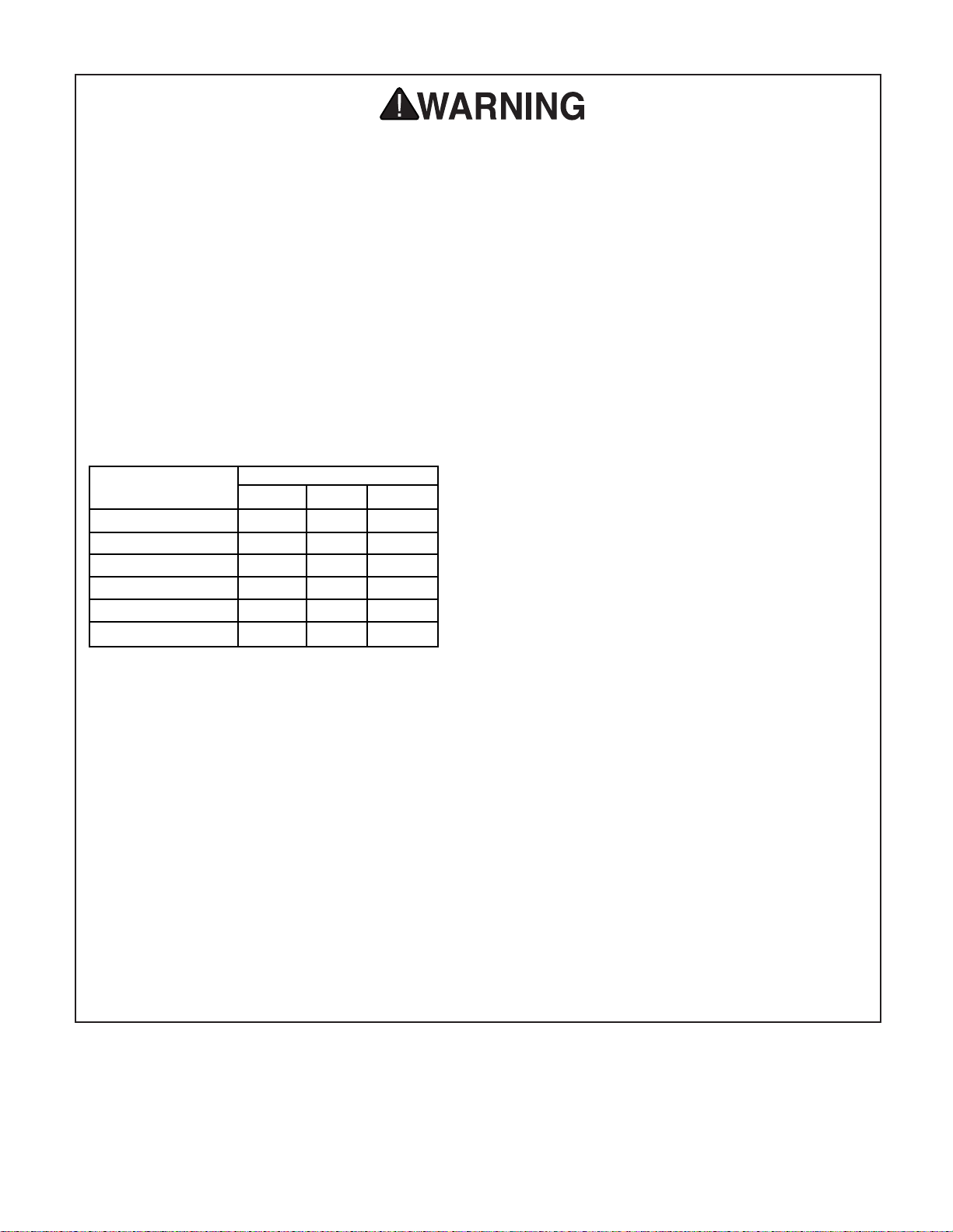
9. USE PROPER EXTENSION CORD. Make
sure your extension cord is in good condition. Conductor size should be in accordance
with the chart below. The amperage rating
should be listed on the motor or tool nameplate. An undersized cord will cause a drop
in line voltage resulting in loss of power and
overheating. Your extension cord must also
contain a ground wire and plug pin. Always
repair or replace extension cords if they
become damaged.
Minimum Gauge for Extension Cords
10. WEAR PROPER APPAREL. Do not wear
loose clothing, gloves, neckties, rings,
bracelets, or other jewelry which may get
caught in moving parts. Non-slip footwear is
recommended. Wear protective hair covering to contain long hair.
11. ALWAYS USE SAFETY GLASSES. Also
use face or dust mask if cutting operation is
dusty. Everyday eyeglasses only have
impact resistant lenses, they are NOT safety
glasses.
12. SECURE WORK. Use clamps or a vise to
hold work when practical. It’s safer than
using your hand and frees both hands to
operate tool.
LENGTH
AMP RATING 25ft 50ft 100ft
0-6 18 16 16
7-10 18 16 14
11-12 16 16 14
13-16 14 12 12
17-20 12 12 10
21-30 10 10 No
Safety Instructions For Power Tools
13. DON’T OVERREACH. Keep proper foot-
ing and balance at all times.
14. MAINTAIN TOOLS WITH CARE. Keep
tools sharp and clean for best and safest
performance. Follow instructions for lubricating and changing accessories.
15. DISCONNECT TOOLS before servicing
and changing accessories, such as blades,
bits, cutters, and the like.
16. REDUCE THE RISK OF UNINTENTIONAL STARTING. Make sure switch is in off
position before plugging in.
17. USE RECOMMENDED ACCESSORIES.
Consult the owner’s manual for recommended accessories. The use of improper
accessories may cause risk of injury.
18. CHECK DAMAGED PARTS. Before fur-
ther use of the tool, a guard or other part
that is damaged should be carefully
checked to determine that it will operate
properly and perform its intended function.
Check for alignment of moving parts, binding of moving parts, breakage of parts,
mounting, and any other conditions that
may affect its operation. A guard or other
part that is damaged should be properly
repaired or replaced.
19. NEVER LEAVE TOOL RUNNING UNATTENDED. TURN POWER OFF. Don’t
leave tool until it comes to a complete stop.
Page 6
-4- G1033 20" Planer
Additional Safety Instructions For Planers
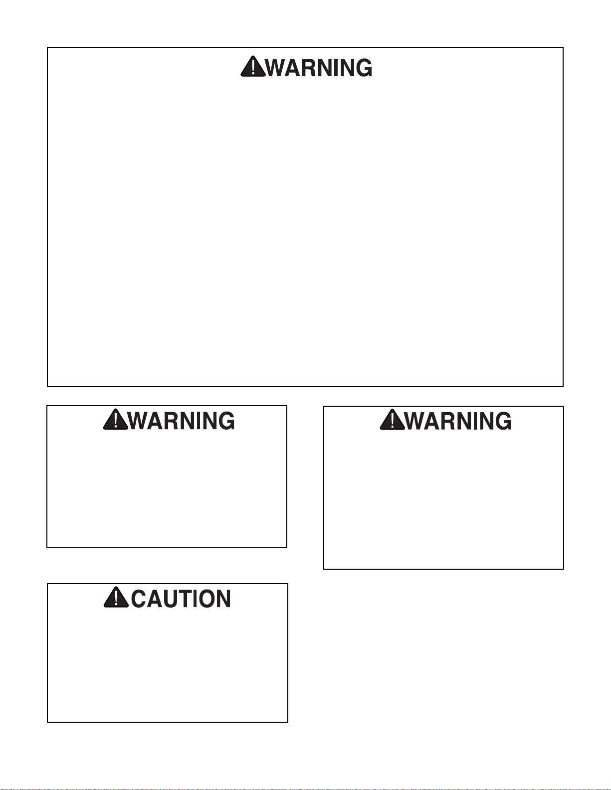
No list of safety guidelines can be complete. Every shop environment is different.
Always consider safety first, as it applies to
your individual working conditions. Use
this and other machinery with caution and
respect. Failure to do so could result in
serious personal injury, damage to equipment or poor work results.
1. Ensure that the machine sits firmly on the
floor before use. Any “wobbles” must be
corrected by shimming or blocking before
operation.
2. This machine is not designed to process
any other material except wood.
3. Never position fingers or thumbs near the
infeed roller.
4. Long stock should always be fully support-
ed by some type of support fixture.
5. Do not operate planer with dull or damaged
knives.
6. Ensure that the planer is properly adjusted
before using.
7. Do not remove excessive amounts of
wood in a single pass.
8. Inspect your stock before planing. Reject
stock with defects and foreign material
9. Do not attempt to remove jams until power
is disconnected and all moving parts have
come to a complete stop.
10. Provide adequate infeed and outfeed
space for operating the planer.
11. Do not plane wood less than 12" long and
1
⁄
4" thick.
12. Do not plane lumber with loose knots or
knots that may become loose during
planing.
Operating this equipment has the potential
to propel debris into the air which can
cause eye injury. Always wear safety glasses or goggles when operating equipment.
Everyday glasses or reading glasses only
have impact resistant lenses, they are not
safety glasses. Be certain the safety glasses you wear meet the appropriate standards of the American National Standards
Institute (ANSI).
Like all power tools, there is danger associated with the Model G1033 20" Planer.
Accidents are frequently caused by lack of
familiarity or failure to pay attention. Use
this tool with respect and caution to lessen
the possibility of operator injury. If normal
safety precautions are overlooked or
ignored serious personal injury may occur.
Page 7

G1033 20" Planer -5-
220V Operation
SECTION 2: CIRCUIT REQUIREMENTS
The Model G1033 should be fused at 30 amps.
Fusing at amperage ratings higher than 30 amps
will not adequately protect the motor. You are
cautioned that equipment that is returned to us
for service that shows evidence of being overfused will be repaired or replaced totally at the
customer’s expense, regardless of the present
warranty status.
Fusing
We do not recommend the use of extension cords
on 220V equipment. It is much better to arrange
the placement of your equipment and the
installed wiring to eliminate the need for extension cords. Should it be necessary to use an
extension make sure the cord is rated Hard
Service (grade S) or better. Refer to the chart in
Section 1: Safety Instructions to determine the
minimum gauge for the extension cord. The
extension cord must also contain a ground wire
and plug pin. Always repair or replace extension
cords when they become worn or damaged.
Extension Cords
Grounding
This equipment must be grounded. Please
ensure that this machine is continuously
grounded from the motor to the machine frame
and then to a known ground. Verify that any
existing electrical outlet and circuit you intend
to plug into is actually grounded. If it is not, it
will be necessary to run a separate 12 A.W.G.
copper grounding wire from the outlet to a
known ground. Under no circumstances should
the grounding pin from any three-pronged plug
be removed. Serious injury may occur.
Figure 1. Twist-lock style 30A connector.
In the event of an electrical short, grounding
reduces the risk of electric shock by providing a
path of least resistance to disperse electric current. This tool is equipped with a power cord having an equipment-grounding conductor. The outlet must be properly installed and grounded in
accordance with all local codes and ordinances.
The 3 HP G1033 Planer motor is wired to operate at 220V only. A 220V plug that matches your
220V receptacle must attach to the end of the
power cord. Plugs and receptacles can be purchased at your local hardware store or home
center. When connecting to 220V, ensure that
the electrical circuit is in fact a 220V circuit.
Contact your local electrical contractor if uncertain about converting to 220V operation. A wiring
diagram for the motor and switch is provided at
the back of this manual should more detail be
needed.
When operating at 220V, we recommend using a
NEMA-style 6-30 plug and outlet. See Figure 1.
You may also “hard-wire” the planer directly to
your panel, provided you place a disconnect
switch near the machine.
Page 8

-6- G1033 20" Planer
SECTION 3: INTRODUCTION
Commentary
We are proud to offer the Grizzly Model G1033
20" Planer. The Model G1033 is part of a growing
Grizzly family of fine woodworking machinery.
When used according to the guidelines set forth
in this manual, you can expect years of troublefree, enjoyable operation and proof of Grizzly’s
commitment to customer satisfaction.
The Model G1033 is designed for heavy-duty professional use. It features a powerful 3HP,
220V/240V single-phase motor, four-knife cutterhead, 2-speed automatic feed, precision-ground
table and a both a chipbreaker and a pressure
bar to support the stock as it moves through the
machine.
A number of optional accessories for the Model
G1033 are available through the Grizzly catalog.
They include a heavy-duty mobile base, roller
stands, replacement knives and Planer Pal
®
planer jigs, which are invaluable when setting up or
adjusting your planer’s cutting knives.
We are also pleased to provide this manual with
the Model G1033. It was written to guide you
through assembly, review safety considerations,
and cover general operating procedures. It represents our effort to produce the best documentation possible. If you have any comments regarding this manual, please write to us at the address
below:
Grizzly Industrial, Inc.
C
/O Technical Documentation
P.O. Box 2069
Bellingham, WA 98227-2069
Most importantly, we stand behind our machines.
If you have any service questions or parts
requests, please call or write us at the location
listed below.
The specifications, drawings, and photographs
illustrated in this manual represent the Model
G1033 as supplied when the manual was prepared. However, owing to Grizzly’s policy of continuous improvement, changes may be made at
any time with no obligation on the part of Grizzly.
Whenever possible, though, we send manual
updates to all owners of a particular tool or
machine. Should you receive one, we urge you to
insert the new information with the old and keep
it for reference.
Grizzly Industrial, Inc.
1203 Lycoming Mall Circle
Muncy, PA 17756
Phone: (570) 546-9663
Fax: (800) 438-5901
E-Mail: techsupport@grizzly.com
Web Site: http://www.grizzly.com
To operate this, or any power tool, safely
and efficiently, it is essential to become as
familiar with its characteristics as possible.
The time you invest before you begin to use
your Model G1033 will be time well spent.
DO NOT operate this machine until you are
completely familiar with the contents of this
manual. Make sure you read and understand all of the safety procedures. If you do
not understand something, DO NOT operate the machine.
Page 9
G1033 20" Planer -7-
Unpacking
This planer is shipped from the factory in a carefully packed carton. If you find the machine to be
damaged after you’ve signed for delivery and the
truck and driver are already gone, you will need
to file a freight claim with the carrier. Save the
containers and all packing materials for inspection by the carrier or their agent. Without the
packing materials, filing a freight claim can be difficult. If you need advice regarding this situation,
please call us immediately.
The Model G1033 is a heavy machine (770
lbs. shipping weight). DO NOT over-exert
yourself while unpacking or moving your
machine – get assistance. In the event that
your planer must be moved up or down a
flight of stairs, be sure that the stairs are
capable of supporting the combined weight
of people and the machine. Failure to use
care while assembling or moving could
result in serious personal injury.
Parts Inventory
Take a quick inventory of the parts and put them
aside for assembly later. After all the parts have
been removed from the container, you should
have:
• Planer Unit
• Dust Hood
• Hand Wheel
• Starter Switch
• Rollers (2)
• Knife Gauge
• Bolt Bag
(2) 12mm Snap Rings
(2) 10mm Flat Washers
(8) M10x1.5 Hex Bolts
(8) 6mm Flat Washers
(4) Snap Rings
(6) M10x1.5 Hex Bolts
(6) Flat Washers
In the event that any non-proprietary parts are
missing (e.g. a nut or a washer), we would be
glad to replace them, or, for the sake of expediency, replacements can be obtained at your local
hardware store.
NOTICE
A full parts list and breakdown can be found
toward the end of this manual. For easier
assembly, or to identify missing parts,
please refer to the detailed illustrations at
the end of the manual.
Page 10
-8-
G1033 20" Planer
Site Considerations
FLOOR LOAD
Your G1033 Planer represents a large weight
load in a small footprint. Most commercial floors
are suitable for the Model G1033. Some residential floors may require additional build up to support both machine and operator.
WORKING CLEARANCES
Working clearances can be thought of as the distances between machines and obstacles that
allow safe operation of every machine without
limitation. Consider existing and anticipated
machine needs, size of material to be processed
through each machine, and space for auxiliary
stands and/or work tables. Also consider the relative position of each machine to one another for
efficient material handling. Be sure to allow yourself sufficient room to safely run your machines in
any foreseeable operation.
LIGHTING AND OUTLETS
Lighting should be bright enough to eliminate
shadow and prevent eye strain. Electrical circuits
should be dedicated or large enough to handle
combined motor amp loads. Outlets should be
located near each machine so power or extension cords are not obstructing high-traffic areas.
Be sure to observe local electrical codes for proper installation of new lighting, outlets, or circuits.
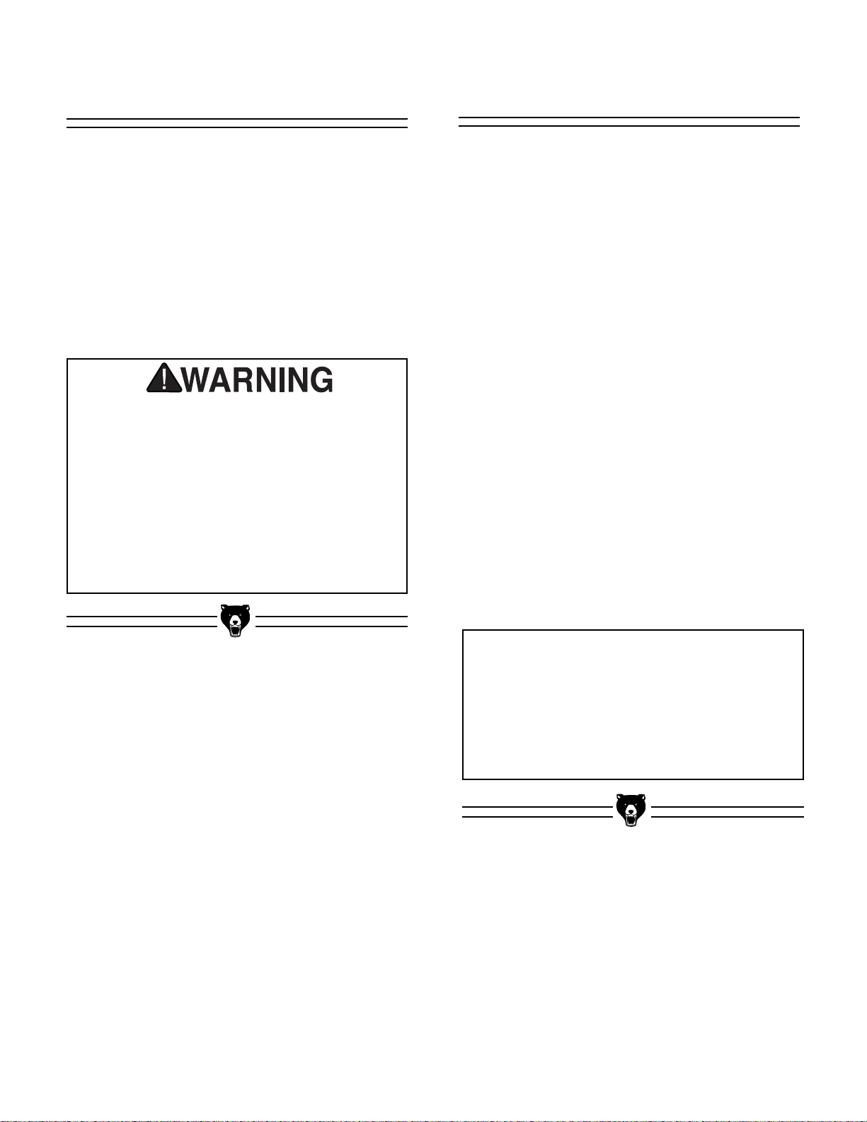
Make your shop “child safe”. Ensure that
your workplace is inaccessible to youngsters by closing and locking all entrances
when you are away. Never allow visitors in
your shop when assembling, adjusting or
operating equipment.
Clean Up
The unpainted surfaces are coated with a waxy
oil to protect it from corrosion during shipment.
Remove this protective coating with with a solvent cleaner or citrus-based degreaser. Avoid
chlorine-based solvents as they may damage
painted surfaces should they come in contact.
Always follow the usage instructions on the product you choose for clean up.
Many of the solvents commonly used to
clean machinery can be highly flammable,
and toxic when inhaled or ingested. Always
work in well-ventilated areas far from potential ignition sources when dealing with solvents. Use care when disposing of waste
rags and towels to be sure they do not create fire or environmental hazards. Keep children and animals safely away when cleaning and assembling this machine.
Do not use gasoline or other petroleumbased solvents to remove this protective
coating. These products generally have
low flash points which makes them
extremely flammable. A risk of explosion
and burning exists if these products are
used. Serious personal injury may occur.
Some die-cut metal parts may have sharp
edges (called “flashing”) on them after they
are formed. Please examine the edges of all
die-cut metal parts before handling them.
Failure to do so could result in injury.
Page 11
G1033 20" Planer -9-
SECTION 4: ASSEMBLY
Overview
Most of your G1033 Planer has been assembled
at the factory, but some parts must be assembled
or installed after delivery. We have organized the
assembly process into steps. Please follow along
in the order presented here.
TOOLS REQUIRED: Most of the tools required
for assembly are included with the planer.
However, you will also need a Phillips
®
and regular screwdriver, metric wrenches, as well as a
feeler gauge for adjustments.
Extension Rollers
The Model G1033 is supplied with extension
rollers on both the infeed and outfeed ends of the
table. The roller assemblies are identical for both
infeed and outfeed. To attach the extension
rollers:
1. Attach an extension bar to the end of each
roller and secure with the 12mm snap rings
provided.
2. The assembled extension rollers attach to
the ends of the planer’s table. Match the
tapped holes on the side of the table to the
extension bars and attach with the M10 x
1.5 Hex Bolts and washers provided. See
Figure 2.
3. Before final tightening, run a straight edge
across the table and past each roller.
Position the rollers flush with the table and
tighten the Hex Bolts securely.
Figure 2. Extension roller attachment.
Extension
Mounting Bolts
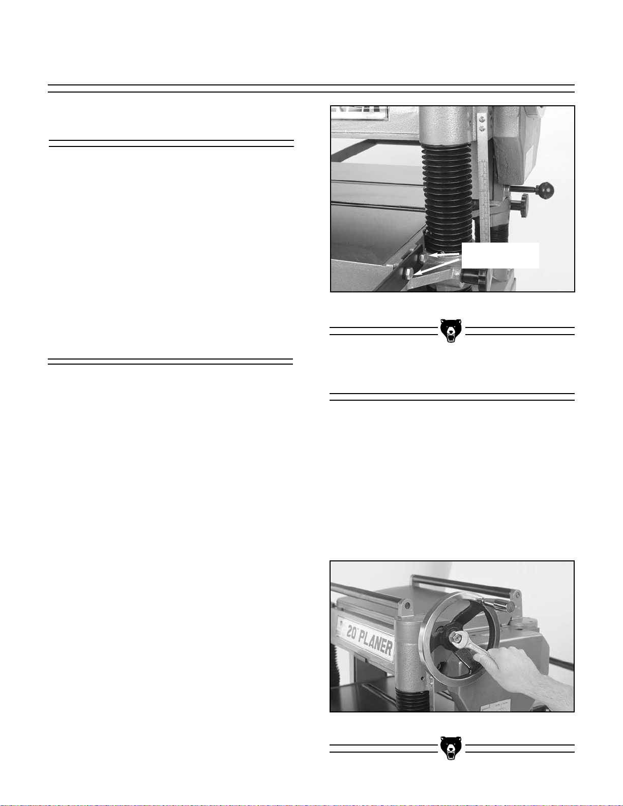
Hand Wheel
The hand wheel operates the chain driven system which raises and lowers the table to control
cutting depth. To attach the hand wheel:
1. Place the handwheel on the worm gear
shaft and secure with hex nut and washer
provided. See Figure 3.
2. Attach the handle to the handwheel and
tighten hex nut.
Figure 3. Attaching handwheel.
Page 12

-10- G1033 20" Planer
Dust Hood
The G1033 features a dust hood with a 5'' dust
port. It is only to be used in conjunction with a
dust collection system. Install the dust hood as
follows:
1. Match the mounting holes on the dust hood
with the tapped holes on the outfeed end of
the cutterhead casting.
2. Using the six M6-1.0 Hex bolts provided,
secure the dust hood to the cutterhead
casting. See Figure 4.
See note regarding the use of a dust collector
and chip deflector adjustment in the adjustment
section of this manual.
Figure 4. Dust hood in place.
Switch
The magnetic ON/OFF switch supplied with the
Planer is pre-wired to the motor. The remaining
step requires connecting the switch to the planer's head casting. To attach the switch:
1. Align the holes on the flanges at the back of
the switch box with the tapped holes on the
front left corner of the head casting.
2. Using the socket head cap screws provid-
ed, attach the switch box assembly to the
head casting. See Figure 5.
The G1033 is shipped without a plug. Now would
be a good time to attach the appropriate plug
specified in Section 2: Circuit Requirements.
Figure 5. Attaching switch.
Do not attempt to make any adjustments to
this machine or perform routine maintenance without unplugging it from its power
source. Serious injury could result.
DO NOT attach the dust hood if you do not
intend to connect the Model G1033 to a dust
collection system. Accumulated wood chips
could cause a malfunction, resulting in personal injury or damage to the planer.
Page 13
G1033 20" Planer -11-
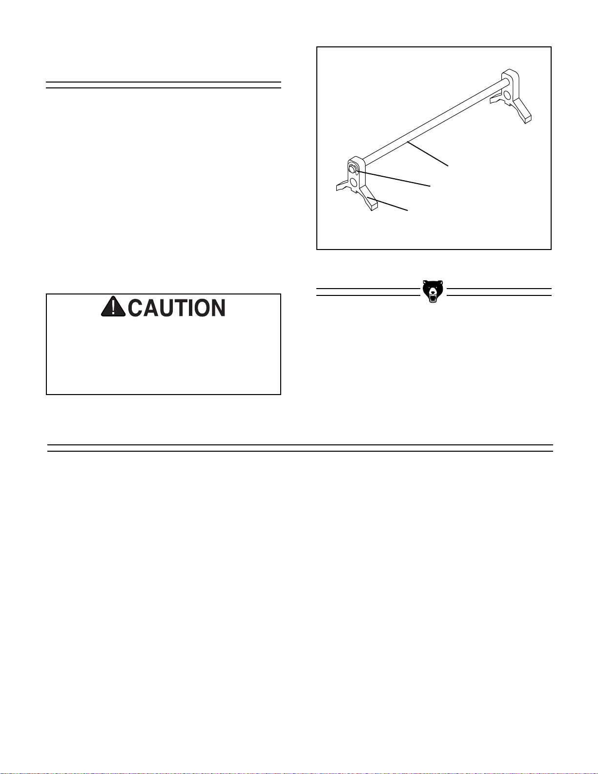
Figure 6. Knife setting jig.
The knife setting jig has been provided to make
knife setting quick and easy. See Figure 6.
To assemble the knife setting jig:
1. Snap one of the E-clips over the notch on
one end of the knife setting rod.
2. Slide the cast aluminum knife setting jig
brackets onto the rod.
3. Snap the other E-clip onto the notch at the
other end of the knife setting jig rod.
E-clip
Jig Rod
Jig Bracket
Knife Setting Jig
Planer knives are dangerously sharp. Use
extreme caution when working near cutting
surfaces. Failure to exercise care while
working near knives could result in severe
injury.
NOTES
Page 14

-12- G1033 20" Planer
Chain Adjustment
SECTION 5: ADJUSTMENTS
The chain drive in the Model G1033 transfers
movement from the hand wheel driven column to
the three other support columns. The chain drive
may require adjustment to remove slack as the
chain stretches over time, or as part of table leveling procedures. To adjust the chain:
1. Remove the two access panels on the
stand.
2. Loosen the two locking bolts and move the
idler sprocket until chain play has been
eliminated. See Figure 7.
3. Re-tighten the two locking bolts.
4. Check chain lubrication. Refer to the
Maintenance Section for further details.
Figure 7. Idler sprocket adjustment.
Table Adjustment
The Model G1033’s table movement is critical to
the operation of the machine. As such, it is
essential that the table is aligned correctly with
the cutterhead and the head casting. For the
power feed to work correctly, it is important that
the table be the same distance from the head
casting in front and back. To make table adjustments, it will be necessary to construct the measurement block ''A''. See page 36 for a full size
print of block ''A''. To adjust the front-to-back distances:
1. Place Block ''A'' on the front right corner of
the table and raise the table until the top of
the block comes in contact with the bottom
of the head casting.
2. Without moving the table position, move
the block to the rear right corner under the
head casting. If the block will not fit under
the head casting, or if the gap between the
head casting and the table exceeds .016''
(use a feeler gauge to determine gap) you
will need to adjust the chain drive. See
Figure 8.
Figure 8. Measurement block in place.
A
Idler Sprocket
Page 15

G1033 20" Planer -13-
Chain Drive
Adjust the chain drive by loosening the chain tensioner and loosen the chain until you can turn
each corner sprocket independently. If the back
of the table is too high, the back two sprockets
will need to be rotated clockwise to lower the
table. Each tooth on the sprocket represents
.016" of vertical movement as the cogs are
turned. Make sure, as you turn the sprocket, to
keep an accurate tooth count to ensure that the
table is lowered equally on both the left and right
sides. Turn the sprockets in small increments
until the front clearance matches the back.
When the front-to-back clearance is within the
.016'' tolerance, tighten the idler sprocket on the
chain drive and tighten the lock bolts.
With the front-to-back adjustments made, we can
concentrate on the alignment between the table
and cutterhead. To check table-to-cutterhead
alignment:
1. Place Block ''A'' on the table under the left
end of the cutterhead. Raise the table until
the block touches the bottom of the cutter-
head. See Figure 9.
2. Slide the block across the table toward the
right side of the cutterhead.
3. If the block becomes too tightly wedged
between the table and the cutterhead, or if
there is a noticeable gap between the block
and the cutterhead, the table will need to be
adjusted.
4. If you find a substantial gap (larger than
.016''), follow the directions above for loosening the chain drive and turn the two right
sprockets (independently of the chain) until
the gap is eliminated. Turn the sprockets
counterclockwise from the bottom to raise
the table.
5. If the table is too high at the right side,
rotate the sprockets in the opposite direction.
Figure 9. Using block to align cutterhead.
Figure 10. Micro-adjustment screws.
When you get the tolerance to within the .016''
range, micro-adjust by loosening the Allen head
cap screws and lifting the table upward or downward until the table and cutterhead are in align-
ment. See Figure 10. This process may require
adjusting the columns on both the left and right
hand sides until you find the correct combination.
REMEMBER: When making adjustments, be
certain to tighten fasteners after each step to
ensure the accuracy of your tests. When adjusting the chain drive, keep in mind that if the chain
becomes too loose, it will fall off of all the sprockets. Returning it to its proper location can be frustrating.
Page 16

-14-
G1033 20" Planer
Bed Rollers
After completing adjustments to the table, align
the bed rollers. The height of the bed rollers will
vary, depending on the type of material you
intend to plane. When planing rough stock, you
will need to set the rollers high to keep the lumber from dragging along the bed. Milled lumber
should be planed with the rollers set lower. To
adjust the rollers correctly:
1. Lay a good quality straightedge across
both bed rollers, using a machinist's square
to keep the straightedge perpendicular to
the table.
2. Using a feeler gauge, measure the dis-
tance between the straightedge and the
table. The tolerance between the table and
the straightedge should be the same
across the table. The ideal tolerance
should be between 0'' and .015'', the larger
measurement for rougher stock. See
Figure 11. Be careful using the larger toler-
ance. Anytime the rollers are higher than
the table the potential exists for snipe, or
gouging near the end of the board
Figure 12. Roller height adjustment.
Figure 11. Bed roller tolerances.
4. Once your roller heights are corrected, re-
tighten the setscrews.
5. Spin the rollers and inspect for free move-
ment.
3. To adjust the rollers, loosen the setscrews
at the left end of the rollers and, using an
Allen
®
wrench, raise or lower the rollers on
their eccentric shafts to reach your desired
height across the table. See Figure 12.
Planer knives are dangerously sharp. Use
extreme caution when working near cutting
surfaces. Failure to exercise care while
working near knives could result in severe
injury.
Page 17

G1033 20" Planer -15-
Knife Inspection
The G1033 20" Planer comes equipped with a 4knife cutterhead. The knives must be periodically
replaced or adjusted. Adjustments should be as
precise as possible with tolerances within ±.001''
to prolong the sharpness of the knife edges.
Improperly adjusted knives can unbalance the
cutterhead and shorten bearing life, as well as
produce substandard planing results. The knives
are set at the factory before shipping, but now is
a good time to double-check. To inspect and
adjust knife set:
1. Remove the upper cover to expose the top
of the cutterhead.
2. Carefully turn the cutterhead (using the pul-
ley) until the first knife is top dead center.
3. Using the knife adjusting jig, check the
knife height. The jig should sit solidly with
both feet on the cutterhead. See Figure 13.
If the knife is adjusted properly, the contact
point at the center of each adjuster should
just touch the tip of the knife. If the knife
does not make contact, or if the knife causes the adjuster’s legs to not seat on the cutterhead, the knives need to be adjusted.
Figure 13. Knife height adjustment.
Knife Adjustment
The knives are locked into the cutterhead with
wedge type gibs and gib bolts. Springs under the
knives give an upward pressure to help in the setting process. To re-align the knives:
1. Loosen the gib bolts until the knife is forced
upward by the springs. The gib bolts turn
clockwise to loosen and counterclockwise
to tighten (when facing the head of the
bolt). See Figure 14.
2. Place the adjusters on the cutterhead as
described above, so the feet are securely
planted on the cutterhead. Make sure the
adjuster extension rod is parallel to the cutterhead, so both ends of the knife receive
equal pressure from the adjuster.
3. The downward pressure provided by the
adjuster will set the knives at a uniform protrusion of approximately .070" above the
cutter. The knife height should vary no
more than .001" across the length of the
cutterhead.
4. Maintain a constant pressure on the
adjuster while re-tightening the gib bolts.
5. Repeat the same procedure on the remain-
ing knives. As mentioned before, the standard adjuster is satisfactory for reasonably
accurate knife setting tasks.
Figure 14. Cutterhead assembly.
Loosen
Tighten
Page 18

-16- G1033 20" Planer
5. Place Block ''A'' under the cutterhead with a
.040'' feeler gauge above it and raise the
table until the block reaches the cutterhead.
Center one of the knives at the bottom of
the cutterhead as you raise the table. Rock
the cutterhead backward and forward as
you raise the table and stop when the knife
just touches the feeler gauge. See Figure
17.
6. The table is now positioned correctly. Lock
the table in place.
7. Remove the feeler gauge and move the
block to the right end of the infeed drive
roller.
Feed Roller Speed
The infeed and outfeed rollers power the stock
through the planer. They keep boards flat and
provide smooth movement. The power feed features two feed rates - 16 FPM and 20 FPM. The
speed can be changed by moving the feed con-
trol knob when the machine is running. See
Figure 15. Moving the knob toward the machine
(Pos B) produces the 20 FPM feed speed, away
from the machine (Pos D) produces 16 FPM and
a center position (Pos C) places the gearbox in
neutral.
Figure 15. Feed speed control.
Roller Adjustment
The infeed and outfeed rollers must be set at
.040" below the level of the cutting edge of the
knives. To set the height of the infeed and outfeed rollers:
1. Disconnect the planer from its power
source.
2. Make sure the knives are set correctly.
3. Remove the chain cover. Refer to the pre-
run check for removal instruction.
4. Loosen the cap screw that holds the static
chain tensioner and swing the tensioner out
of the way. See Figure 16.
Figure 16. Static chain tensioner adjustment.
NOTICE
The feed rate must be set before feeding
lumber into the planer. DO NOT attempt to
change speeds after the planing operation
has begun. Damage to the gearbox will
result.
Page 19

G1033 20" Planer -17-
8. Move the feed speed control knob to the
center neutral position.
9. Rotate the sprocket at the end of the
infeed roller. The teeth at the bottom of the
roller should contact the top of the block if
the roller is properly adjusted. If the roller
teeth will not clear the block, or if there is a
gap between the block and the infeed
roller, you will need to make adjustments.
10. If you need to adjust the roller up or down,
loosen the lock nut and turn the setscrew
to raise or lower the rollers. See Figure 18.
Figure 17. Feeler measures roller adjustment.
11. Follow the same procedure at the other
end of the infeed roller and on both sides
of the outfeed roller. Do not change the
table height yet, the next sections will
require the same settings.
12. Be sure to tighten the lock nut as soon as
you have adjusted each roller to its proper
height.
Figure 18. Adjusting roller height.
A
Spring Tension
Roller spring tension must be adjusted so that
roller pressure is uniform. To adjust roller spring
tension:
1. Locate the four adjustment screws located
on the top of the planer. See Figure 19.
2. Adjust screws #1 - #3 so that they protrude
1
⁄
8" above the head casting.
3. Adjust screw #4 so that it protrudes
5
⁄16"
above the head casting.
Figure 19. Tension screw locations.
Tension screws #1 - #3
Tension screw #4
Page 20

-18- G1033 20" Planer
2. Place your test block under the middle of
the chipbreaker (the table should still be at
the same height as it was when you set the
infeed and outfeed rollers).
3. Loosen the lock nuts at both ends of the
chipbreaker and turn the setscrews to raise
or lower the chipbreaker as necessary. The
chipbreaker will move evenly, so it does not
matter which setscrew you turn. (You will
need to raise the second setscrew if the
chipbreaker needs to be lowered).
4. When the chipbreaker reaches its proper
height .040'' below the cutterhead height,
tighten the lock nut and adjust the other
setscrew and lock nut to match.
Figure 20. Chipbreaker adjustment.
Chipbreaker
The chipbreaker breaks chips/curls as they are
cut by the cutterhead and forces chips to eject
from the cutting area. Due to its functions within
the planer, the chipbreaker should be adjusted
carefully and checked frequently for movement.
To adjust the chipbreaker:
1. Disconnect planer from its power source
and remove the top cover. Note the location
of the setscrews and lock nuts. See Figure
20.
Pressure Bar
Like the chipbreaker, the pressure bar controls
lumber as it passes under the cutterhead. The
pressure bar keeps lumber from lifting after it has
been planed. If the pressure bar is incorrectly
positioned, a number of machining defects
(including snipe and board lines) can result. A
pressure bar set too low can also place excess
load on the planer’s motor. The pressure bar
should be adjusted along with the infeed and outfeed rollers. To adjust the pressure bar:
1. Disconnect the planer from its power sup-
ply.
2. Remove top cover. Note setscrew and lock
nut pictured in Figure 21. Loosen the lock
nuts.
3. Place the gauge block under the center of
the pressure bar and adjust the setscrew
until the pressure bar makes slight contact
with the tip of the block. Like the chipbreaker, the pressure bar can be adjusted
with one setscrew. Make sure to adjust the
second setscrew to match the one you’ve
just adjusted.
4. Tighten the lock nut in place.
Figure 21. Pressure bar adjustment.
Page 21

G1033 20" Planer -19-
Chip Deflector
The chip deflector keeps chips from falling onto
the outfeed roller. To adjust the deflector:
1. Disconnect the planer from its power
source and remove the planer’s dust cover.
2. Loosen the deflector’s mounting bolts. See
the parts diagram for location.
3. Make sure the deflector is beveled toward
the cutterhead. Move the deflector until the
edge is approximately
1
⁄16'' from the tip of
the cutting knives. Rotate the cutterhead to
ensure clearance.
4. Re-tighten the mounting bolts and return
the top cover to the planer.
Static Chain Adjuster
Once the rollers, chip breaker and pressure bar
are properly adjusted, you will need to reset the
static chain tensioner. Proper tensioner adjustment is crucial to your planer’s operation. Not
only will it have a direct effect on the quality of
your work, incorrect tension on the drive chain
may cause the rollers to jam, or cause the chain
to break. To adjust the static chain tensioner:
1. Place the test block under the right side of
the outfeed roller. Make sure that the block
and the roller are in slight contact.
2. Note the height of the table on the metric
portion of the scale below the handwheel.
Crank the handwheel until the table moves
one millimeter towards the head casting.
The outfeed roller will have lifted .040''.
3. Rotate the static chain tensioner up until
the chain is tight. See Figure 22.
4. Once the chain is tight, secure the screw
that holds it in place and lower the table
until you can remove the block.
5. When the tensioner is correctly adjusted,
replace the backing plate and the chain
drive cover.
Figure 22. Chain tensioner adjustment.
NOTICE
When using a dust collector, it may be necessary to increase the distance from the
cutterhead/knives to the deflector to aid in
chip removal.
Page 22

-20- G1033 20" Planer
The scale can be adjusted for accuracy. The
machine will need to be run to make proper
adjustments. Follow the directions on the following page for a test run before attempting to make
adjustments. Once you’ve successfully tested the
planer:
1. Set the table to the approximate thickness
of your test lumber. Measure the lumber
with calipers to determine its exact thickness.
2. Move the table to
1
⁄16'' under the thickness
of your lumber and feed your test board
through the planer.
3. Turn the handwheel one full rotation and
run the board through once more. Turn the
board over and repeat.
4. Re-measure the board and compare your
results with the scale. If there is a discrepancy, loosen the Allen
®
head bolts and
adjust to match your findings. See Figure
23.
Scale Adjustment
The Model G1033 provides an anti-kickback system as a safety feature. The anti-kickback fingers
hang from a rod suspended across the cutterhead casting. The anti-kickback fingers should be
inspected regularly. Check the fingers to ensure
that they swing freely and easily. See Figure 24.
Do not apply oil or other lubricants to the antikickback fingers. Oil or grease will attract dust,
restricting the free movement of the fingers.
Anti-Kickback Fingers
Figure 23. Cutterhead height scale.
Figure 24. Anti-kickback fingers.
Proper operation of the anti-kickback fingers are essential for the safe operation of
this machine. Failure to ensure that they are
working properly could result in serious
operator injury.
Page 23

G1033 20" Planer -21-
1. Inspect lumber for defects, warping, cupping,
twisting, and for foreign objects (nails, staples, imbedded gravel, etc,). If you have any
question about the quality of your lumber, do
not use it. Remember, wood stacked on a
concrete floor can have small pieces of stone
or concrete pressed into the wood.
2. Use the full width of the planer. Alternate
between the left, the right and the middle
when feeding lumber into the planer. Your
knives will remain sharp much longer.
3. Scrape all glue off of joined boards before
planing.
4. Plane ONLY natural wood fiber. No wood
composites.
5. Surface wood with the grain. NEVER feed
end-cut or end-grained lumber into your
planer.
6. Do not use boards with knots, splits, cross-
grain or other obvious blemishes or defects.
They can damage the machine and pose the
possibility of operator injury.
7. Keep your work area clear.
8. When making multiple passes through the
planer on long stock, use the stock return
rollers on the top of the machine to move the
material back to the infeed side of the
machine.
9. Avoid planing wood with a high water con-
tent. Wood with more than 20% moisture
content or wood exposed to rain or snow, will
plane poorly and cause excessive wear to
the knives and motor. Excess moisture can
also hasten rust and corrosion.
Operational Tips
Once the assembly is complete and the adjustments are done to your satisfaction, you are
ready to test the machine.
Turn on the power supply at the main panel.
Press the START button. Make sure that your finger is poised on the STOP button, just in case
there is a problem. The planer should run
smoothly, with little or no vibration or rubbing
noises. Strange or unnatural noises should be
investigated and corrected before operating the
machine further.
Test Run
SECTION 6: Operations
DO NOT attempt to investigate or adjust the
machine while it is running. Wait until the
machine is turned off, unplugged and all
working parts have come to a rest before
you do anything!
If noises occur that cannot be found by visual
inspection, feel free to contact our service department for help.
Operating this equipment has the potential
for flying debris to cause eye injury.
Always wear safety glasses or goggles
when operating equipment. Everyday
glasses or reading glasses only have
impact resistant lenses, they are not safety
glasses. Be certain the safety glasses you
wear meet the appropriate standards of the
American National Standards Institute
(ANSI).
Page 24

-22-
G1033 20" Planer
Wood Characteristics
The species of wood, as well as condition, will
affect planing ability. The harder the wood, the
more difficult it will be to plane. We’ve included
below, a list of wood characteristics you may
encounter when planing. The following descriptions of defects will give you some possible
answers to problems you may encounter while
planing different materials. Possible solutions follow the descriptions.
Chipped Grain - usually a result of cutting
against the grain, or planing wood with knots or
excessive amount of cross grain. Chipped grain
can also be caused by dull knives or misaligned
chipbreaker. Often, chipped grain can be avoided
by slowing down the feed rate and by taking shallow cuts. If those options do not work, inspect
your lumber and determine if its grain pattern is
causing the problem. If the wood does not show
substantial crossgrain, inspect your knives for
sharpness and inspect the chipbreaker for proper alignment. See the Adjustment Section.
Fuzzy Grain - Usually caused by surfacing lum-
ber with too high a moisture content. Sometimes
fuzzy grain is a characteristic of some woods,
such as basswood. Fuzzy grain can also be
caused by dull knives or an incorrect grinding
bevel. Check with a moisture meter. If moisture is
greater than 20%, sticker the wood and allow to
dry. Otherwise, inspect knife condition.
Glossy Surface - Usually caused by dull knives
taking shallow cuts at a slow feed speed. Surface
gloss will usually be accompanied by overheating. Often, lumber will be scorched and eventually, damage to knives will occur. If knives are
sharp on inspection, increase feed speed and/or
cutting depth.
Snipe - Occurs when board ends have more
material removed than the rest of the board.
Usually caused when one or both of the bed
rollers are set too high. Can also be caused by
the chipbreaker or pressure bar being set too
high. However, small amount of snipe is
inevitable.
Snipe can be minimized by proper adjustment of
the planer’s components, but complete removal
of snipe is extremely unlikely. More likely, you will
be able to reduce it to a tolerance of .002". If
snipe under that level is a problem, consider
planing lumber longer than your intended work
length and cut off the excess after planing is completed.
Uneven Knife Marks - Uneven knife marks can
occur when the chipbreaker is set too high.
Inspect cutterhead bearings if re-adjustment of
the chipbreaker fails to remedy the situation.
Chatter Marks - Usually caused by incorrect
chipbreaker and pressure bar setting heights.
Chatter marks can also be caused by running a
narrow wood piece through the planer at either
the right or left end of the cutterhead. Chatter, like
uneven knife marks, will show in the form of a
''washboard'' look. Chatter marks are more likely
to be inconsistent in appearance than uneven
knife marks.
Wavy Surface - Caused by poor knife height
adjustment, wavy surface appears when one
knife is taking deeper cuts than the rest of the
knives. Remedy by re-setting the knives to a tolerance of ± .001".
Pitch & Glue Build-up - Glue and resin build-up
on the rollers and cutterhead will cause overheating by decreasing cutting sharpness while
increasing drag in the feed mechanism. The
result can include scorched lumber as well as
uneven knife marks and chatter.
Chip Marks - Occur when chips aren’t properly
expelled from the cutterhead. The knives catch
the chips and drag them across the lumber being
planed. Chips tend to be random and non-uniform (as compared to chipped grain). Can be
caused by exhaust blockage or too much room
between the cutterhead and chip deflector. Using
a dust collection system in combination with the
planer can help reduce chip marks. Inspect the
chip deflector and readjust (as described earlier
in the text).
Page 25

G1033 20" Planer -23-
SECTION 7: MAINTENANCE
Make a habit of inspecting your planer each time
you use it. Check for the following conditions and
repair or replace when necessary.
1. Loose mounting bolts.
2. Worn switch.
3. Worn or damaged cords and plugs.
4. Damaged V-belts.
5. Any other condition that could hamper the
safe operation of this machine.
General
Knife Sharpening
Knife sharpness is one of the most important factors in getting good results with the planer. Knives
can be made to last a long time if care is taken in
checking the condition of the wood which is put
into the machine. The biggest problem will come
from wood with nails or other metal embedded.
This will nick or chip the knives and can require a
complete regrinding. Another wear factor is sand,
grit, or other dirt on the surface of the wood which
the knives have to cut through. At the speed the
cutterhead is rotating, these types of surface contamination can have a very abrasive effect.
This planer has knives with a grind angle of 45˚
which is a configuration which should suit most
general planing needs. The optimal grind or bevel
angle is a compromise between effective cutting
(the smaller the angle the better the cutting
action) and edge life where the larger the angle
the more the edge is supported, thus the longer it
will last.
For the best results it is best to have planer
knives sharpened by a professional sharpening
service which has the grinding and measurement
equipment to assure that the knife cutting geometry is maintained at optimum levels. It is a procedure which requires some care and precision,
otherwise a set of blades can be easily ruined.
Knives should always be ground as a set so they
can be properly matched. Unequal material
removal can result in an unbalanced cutterhead
which can affect not only planing surface quality
but ultimately the life of the cutterhead bearings.
Please refer to Section 5 Adjustments - Knife
Adjustments for complete detail on the removal
and reinstallation of the planer knives.
DO NOT make adjustments or attempt any
maintenance procedures while this machine
is running. Ensure that the switch is off,
power is disconnected and moving parts
have stopped before making any adjustments. Failure to follow this directive could
result in serious operator injury.
Page 26

-24- G1033 20" Planer
Lubrication
The Model G1033 features factory-sealed bearings. A sealed bearing requires no lubrication
during its lifetime. Should a bearing fail, your
planer will probably develop a noticeable rumble,
which will increase when the machine is put
under load. If allowed to get worse, overheating
of the journal containing the bad bearing could
occur. If the bad bearing is not replaced, it will
eventually seize - possibly doing damage to other
parts of the machine. Bearings are standard
sizes and can be replaced through Grizzly.
Proper lubrication of other components of the
Model G1033 are essential for long life and trouble-free operation. Below is a list of components
that require periodic lubrication. Schedules are
based on daily use. Adjust accordingly for your
level of use.
Columns/Lead Screws - The four columns
should be lubricated weekly with light oil.
Unfasten dust covers to gain access. The four
lead screws should be lubricated with general
purpose grease once a month.
Worm Gear - The worm gear should be inspect-
ed monthly and lubricated when needed.
Remove the worm gear box to inspect. See parts
diagram for location.
Chain - The table height adjustment chain should
be inspected monthly and lubricated when needed. A good quality bicycle chain lubricant works
well for periodic lubrication.
Gear Box - Gear box oil should be drained after
the first 20 hours of operation. See Figure 25.
Replace with 80W-90W gear oil. Inspect levels
periodically and change yearly. Replace gear oil
more frequently under heavy use. Fill until oil
reaches the top of the filler plug port for correct oil
level.
Drive Chain - The drive chain should be inspect-
ed and lubricated monthly. Check sprocket, chain
and cotter pin during inspection. Use a general
purpose grease. Some chains will have master
links instead of cotter pins.
Feed Rollers - Daily lubrication of feed rollers is
crucial to the operation of your planer. Lubricate
before start-up. Each end of each power feed
roller has an oiling port located on the top of the
head casting. See Figure 26. Apply a light oil,
making sure that the lubricant penetrates the
bearing.
Figure 25. Gear Box drain and fill plugs.
Figure 26. Feed roller lubrication points.
Fill
Drain
Page 27

G1033 20" Planer -25-
Belt Tension
Inspect the belts daily for the first couple of
weeks you operate the planer. This is the time
that the majority of stretching will occur. Adjust
belt tension by lowering the motor down slightly.
See Figure 27. Establish a periodic schedule of
inspection. Check for wear, cracking, nicks, or
glazing. Replace belts immediately if you spot
any signs of deterioration. Always use three belts
when operating the Model G1033.
Belt Alignment
Proper belt alignment prevents premature belt
wear. See Figure 28. Use a straightedge on the
edge of the pulleys to judge alignment.
Figure 27. Adjustments for belt tension.
Figure 28. Pulley alignment procedure.
Should you find that the pulleys are out of alignment:
1. Loosen the belt tension to allow motor
movement.
2. Loosen the four (4) bolts that secure the
motor to the mounting plate just enough to
allow the motor to be repositioned.
3. Slide the motor as required to align the pul-
leys..
4. Re-tighten the motor mount bolts carefully
to assure that the tightening process does
not move the motor.
5. Re-tension the belt as shown in the previ-
ous column.
6. Replace the belt cover.
Page 28

-26- G1033 20" Planer
The following pages contain parts diagrams, parts
lists, general machine data and warranty/return
information for your Model G1033 Planer.
If you need parts or help in assembling your
machine, or if you need operational information,
we encourage you to call the Grizzly Industrial
Service Department. Our trained service technicians will be glad to help you.
If you have comments dealing specifically with
this manual, please write to our Bellingham,
Washington location using the address in the
Introduction. The specifications, drawings, and
photographs illustrated in this manual represent
the Model G1033 as supplied when the manual
was prepared. However, due to Grizzly’s policy of
continuous improvement, changes may be made
at any time with no obligation on the part of
Grizzly. Whenever possible, though, we send
manual updates to all owners of a particular tool
or machine. Should you receive one, add the new
information to this manual and keep it for reference.
We have included some important safety measures that are essential to this machine’s operation. While most safety measures are generally
universal, Grizzly reminds you that each workshop is different and safety rules should be con-
sidered as they apply to your specific situation.
We recommend you keep a copy of our current
catalog for complete information regarding
Grizzly's warranty and return policy. If you need
additional technical information relating to this
machine, or if you need general assistance or
replacement parts, please contact the Service
Department listed in Section 3: Introduction.
Additional information sources are necessary to
realize the full potential of this machine. Trade
journals, woodworking magazines, and your local
library are good places to start.
SECTION 8: CLOSURE
The Model G1033 was specifically designed
for wood cutting operations. DO NOT MODIFY AND/OR USE THIS PLANER FOR ANY
OTHER PURPOSE. Modifications or improper use of this tool will void the warranty. If
you are confused about any aspect of this
machine, DO NOT use it until you have
answered all your questions. Serious injury
may occur.
Like all power tools, there is danger associated with the Model G1033 20" Planer.
Accidents are frequently caused by lack
of familiarity or failure to pay attention.
Use this tool with respect and caution to
lessen the possibility of operator injury. If
normal safety precautions are overlooked
or ignored serious personal injury may
occur.
Page 29

G1033 20" Planer -27-
Customer Service #: (570) 326-3806 • To Order Call: (800) 523-4777 • Fax #: (800) 438-5901
GRIZZLY MODEL G1033 20" PLANER
MACHINE DATA
SHEET
Design Type .................................................................................................... Floor Model
Overall Dimensions:
Table Size ....................................................................................................25
3
⁄4" x 20"
Height........................................................................................................................41"
Overall Depth ............................................................................................................39"
Overall Width ............................................................................................................58"
Shipping Weight ................................................................................................770 lbs.
Base Dimensions ..................................................................27
1
⁄
2" L x 23" W x 13
3
⁄
4" H
Crate Size ..................................................................................29" L x 40" W x 44" H
Footprint ........................................................................................................22" x 28"
Capacities:
Maximum Depth of Cut ..............................................................................................
1
⁄8"
Maximum Width of Cut..............................................................................................20"
Maximum Cutting Height..........................................................................................8
5
⁄8"
Minimum Stock Thickness ........................................................................................
1
⁄4"
Minimum Stock Length ..............................................................................................7"
Cutterhead Speed ........................................................................................4833 RPM
Cuts per Minute ..................................................................................................19,332
Feed Rates ......................................................................................16 FPM & 20 FPM
Cuts Per Inch ..................................................................................................104 & 83
Construction:
Table ..................................................................................Precision-Ground Cast Iron
Power Feed Rollers ....................................................................Metal/ Spiral Serrated
Stand ........................................................................................................Formed Steel
Cutterhead ........One Piece Machined Shaft; 4 Knife Slots w/ Shielded Ball Bearings
Motor:
Type ............................................................................TEFC Capacitor-Start Induction
Horsepower ............................................................................................................3HP
Phase ⁄ Voltage ................................................................Single Phase / 220V / 240V
Amps ..........................................................................................................................18
Cycle ⁄ RPM ..................................................................................60 Hertz ⁄ 3450 RPM
Switch ........................................................Magnetic With Thermal Overload Protector
Power Transfer ....................................................................................Triple Belt Drive
Bearings..........................................................Shielded & Permanently Lubricated Ball
Features:
Roller Extension Tables ..................................................................1 Adjustable Roller
Table Movement ............................................................................................
1
⁄4" to 81⁄2"
Table Locks................................................................................................Two Positive
Dust Port ....................................................................................................................5"
Measurement Scale ..................................................................................Inch & Metric
Bed Rollers ................................................................................................2 Adjustable
Specifications, while deemed accurate, are not guaranteed.
REVISED 4/99
Page 30

-28- G1033 20" Planer
This section covers the most common processing problems encountered in planing and what to do about
them. Do not make any adjustments until planer is unplugged and moving parts have come to a complete
stop.
TROUBLESHOOTING
SYMPTOM
Motor will not start.
Motor will not start; fuses or
circuit breakers blow.
Motor overheats.
Motor stalls (resulting in
blown fuses or tripped circuit).
Machine slows when operating.
Loud, repetitious noise coming from machine
Machine is loud when cutting. Overheats or bogs
down in the cut.
Infeed roller marks are left
on the workpiece.
Outfeed roller marks are left
on right side of workpiece.
Cannot control snipe.
Chip buildup on outfeed
roller.
Machine howls on startup.
Table moves down while
cutting.
POSSIBLE CAUSE
1. Low voltage.
2. Open circuit in motor or loose
connections.
1. Short circuit in line cord or plug.
2. Short circuit in motor or loose
connections.
3. Incorrect fuses or circuit breakers in power line.
1. Motor overloaded.
2. Air circulation through the motor
restricted.
1. Short circuit in motor or loose
connections.
2. Low voltage.
3. Incorrect fuses or circuit breakers in power line.
4. Motor overloaded.
1. Feed rate too high.
2. Depth of cut too great.
1. Pulley setscrews or keys are
missing or loose.
2. Motor fan is hitting the cover.
3. V-belt is defective
1. Excessive depth of cut.
2. Knives are dull
Depth of cut too shallow.
Too much spring tension on feed
roller.
Long or heavy board sags as it
enters and exits.
Chips working their way back
under the chip deflector.
Chip deflector too close to the
cutterhead.
Knives dull
CORRECTIVE ACTION
1. Check power line for proper voltage.
2. Inspect all lead connections on motor for loose or open connections.
1. Inspect cord or plug for damaged insulation and shorted wires.
2. Inspect all connections on motor for loose or shorted terminals or
worn insulation.
3. Install correct fuses or circuit breakers.
1. Reduce load on motor.
2. Clean out motor to provide normal air circulation.
1. Inspect connections on motor for loose or shorted terminals or
worn insulation.
2 Correct the low voltage conditions.
3. Install correct fuses or circuit breakers.
4. Reduce load on motor.
1. Feed workpiece slower.
2. Reduce depth of cut.
1. Inspect keys and setscrews. Replace or tighten if necessary.
2. Tighten fan or shim cover.
3. Replace V-belt. See Maintenance.
1. Decrease depth of cut.
2. Sharpen knives.
Increase depth of cut.
Refer to Adjustments, Spring Tension.
Lift up on unsupported end of board as it enters and exits cutterhead.
Lay duct tape over the mounting bolts along the outside edge to
seal any possible gaps.
Move back
1
/8" to 1/4" from the cutterhead.
Replace knives.
Page 31

36
37
38
21
44
25
43
1
96
2
97
38
82
81
14
47
37
38
46
44
76
77
75
73
57
37
29
62
63
64
98
66
68
67
35
61
60
58
58
57
57
38
37
56
107
95
95
107
59
54
55
37
38
15
23
80
80
83
85
84
85
15
23
38
37
24
25
23
22
17
23
42
19
20
19
20
40
34
18
20
19
32
39
19
69
109
87
92
93
86
95
88
94
70
25
16
40
51
48
50
49
3
4
13
12
108
89
52
53
5
6
8
78
7
26
26
30
33
35
41
65
79
90
Page 32

-30- G1033 20" Planer
01 P1033001 HEADCASTING
02 PSS13M SETSCREW M10-1.5 X 12
03 P1033003 CUTTERHEAD
04 P1021103 SPRING
05 P1033005 BLADES FOR PLANER
06 P1033006 GIB
07 PB17M HEX BOLT M8-1.25 X 10
08 P1021166 KNIFE GAUGE W/BAR
12 P6206 BEARING 6206
13 PK09M KEY 8 X 8 X 36
14 P1021007 CUTTERHEAD PULLEY
15 P1033015 WASHER 5/16" X 13/16"
16 PSS12M SETSCREW M6-1.0 X 25
17 P1021008 MOTOR PULLEY
18 P1033018 INFEED ROLLER
19 P1021153 BUSHING BLOCK
20 P1021152 SPRING
21 P1033021 SPECIAL SETSCREW
22 P1021092 PLATE
23 PB09M HEX BOLT M8-1.25 X 20
24 PSS11M SETSCREW M6-1.0 X 16
25 PN01M HEX NUT M6-1.0
26 PK21M KEY 5 X 5 X 23
29 PB18M HEX BOLT M6-1.0 X 15
30 P1033030 OUTFEED ROLLER
31 P1021149 SPROCKET
32 P1033032 LOCKING ROD
33 PR03M SNAP RING 12MM
34 P1033034 CHIP BREAKER
35 PN09M HEX NUT M12-1.75
36 P1021028 CHIP BREAKER SPRING
37 PW03M FLAT WASHER 6MM
38 PB03M HEX BOLT M6-1 X 12
39 P1033039 SHAFT
40 P1033040 BRACKET
41 P1033041 PRESSURE PLATE
42 PLW04M LOCK WASHER 8MM
43 P1033043 SHAFT
44 PSS11M SETSCREW M6-1.0 X 16
45 PSS11M SETSCREW M6-1.0 X 16
46 P1033046 SPRING PLATE
47 P1033047 CHIP DEFLECTOR PLATE
48 P1021161 ANTI-KICKBACK FINGER
49 P1021160 SPACER
50 P1033050 SHAFT
51 PEC06M E-CLIP 20MM
52 P1033052 DEPTH LIMITER
53 PFH02M FLT HD SCR M6-1.0X12
54 P1033054 UPPER COVER
55 P1033055 GASKET
56 P1033056 COLLECTOR
57 P1033057 ROLLER STAND
58 P1033058 ROLLER
59 PSB01M CAP SCREW M6-1.0 X 16
60 P1033060 WORM GEAR BOX
61 PSB37M CAP SCREW M6-1.0 X 50
62 P1033062 WORM
63 P6201 BEARING 6201
64 PR29M SNAP RING 32MM
65 PK05M KEY 4 X 4 X 10
66 P1033066 HANDWHEEL
67 P1033067 WASHER 1/2" X 11/8"
68 P1021032 HANDLE
69 P1033069 SCALE
70 PS08M PHLP HD SCR M5-0.8X12
73 P1033073 COVER
75 P1033075 SAFETY HATCH
76 PB04M HEX BOLT M6-1.0X10
77 P1033077 SAFETY HATCH
78 PSB12M CAP SCREW M8-1.25 X 16
79 P1033079 PULLEY GUARD
80 P1033080 STUD
81 PW07 FLAT WASHER 5/16"
82 PN02 HEX NUT 5/
16" X 18
83 PVM59 V-BELT M59 3L590
84 P1033084 PULLEY COVER
85 P1033085 KNOB
86 P1033086 SWITCH BRACKET
87 G4573 MAGNETIC SWITCH
88 PN06M HEX NUT M5-0.8
89 P1033089 NAME PLATE
90 P1183095 RIVET
91 P1033091 CHAIN 33 LINKS
92 P1071075 STRAIN RELIEF
93 P1033093 POWER CORD
94 P1033094 STAR WASHER #10
95 PSB04M CAP SCREW M6-1.0X10
96 PSS14M SETSCREW M8-1.25X12
97 P1033097 RETAINER
98 P1033098 COLLAR
107 PLW03M LOCK WASHER 6MM
108 PS09M PHLP HD SCR M5-0.8X10
109 PSW01-1 PLASTIC SCREW
REF PART # DESCRIPTION REF PART # DESCRIPTION
Page 33

G1033 20" Planer -31-
01 P1033201 MIDDLE TABLE
02 P1033202 ROLLER
03 P6201 BEARING 6201
04 P1033204 ECCENTRIC SHAFT
05 PSS04M SETSCREW M6-1.0X12
06 P1021143 THREADED GIB
07 P1033207 LOCK ROD
08 P1021146 GIB
09 P1021145 KNOB
REF PART # DESCRIPTION
10 PSB14M CAP SCREW M10-1.25X20
11 P1033211 EXT ROLLER BAR
12 P1033212 EXTENSION ROLLER
13 PB32M HEX BOLT M10-1.5X25
14 PW04M FLAT WASHER 10MM
15 P1033071 POINTER
16 PSB04M CAP SCREW M6-1.0X10
17 PLW03M LOCK WASHER 6MM
REF PART # DESCRIPTION
12
11
6
7
4
3
2
5
11
3
9
8
8
9
4
1
11
16
17
15
10
7
12
13
14
11
6
Page 34

01 P1033301 BASE
02 PSS13M SETSCREW M10-1.5 X 12
03 P1033303 COLUMN
04 P1033304 COLUMN
05 P1033305 LEADSCREW
06 P1033306 LEADSCREW
07 P1033307 LEADSCREW NUT
08 P1033308 BUSHING
09 PR22M INT RETAINING RING 38MM
10 PK10M KEY 5 X5 X 12
11 P1033311 GEAR
12 PR03M SNAP RING 12MM
13 P6202 BALL BEARING 6202
14 PR21M SNAP RING 35MM
15 PK08M KEY 5 X 5 X 16
16 P1033316 SPROCKET
REF PART # DESCRIPTION
17 P1033317 WASHER
18 PN08M HEX NUT M10-1.25
19 PW01M FLAT WASHER 8MM
20 PB07M HEX BOLT M8-1.25 X 25
21 P1033321 BRACKET W/ SHAFT
23 P1033323 SPROCKET
24 PR05M SNAP RING 15MM
25 P1033325 CHAIN
26 P1033326 CRANE POST
27 PR08M EXT RETAINING RING 19MM
28 P1033328 PIPE BAND
29 P1033329 SCREW
30 P1033330 EXPANSION BAND
31 PB33M HEX BOLT M12-1.75 X 50
32 PW06M FLAT WASHER 12MM
33 PLW05M LOCK WASHER 12MM
34 PN09M HEX NUT M12-1.75
REF PART # DESCRIPTION
7
7
12
11
3
4
30
9
7
5
3
5
29
28
8
7
10
5
31
32
13
2
13
14
16
1
17
18
21
19
27
20
26
14
33
34
16
17
18
27
6
15
26
25
23
24
Page 35

01 P1033401 STAND
02 P1033402 COVER
03 PFH06M FLAT HD SCREW M6-1.0 X 20
04 P1033404 BAR
05 P1033405 MOTOR MOUNT
06 PSS20M SETSCREW M8-1.25 X 8
07 P1033407 COLLAR
08 P1033408 ADJUSTABLE BOLT
09 PN09M HEX NUT M12-1.75
10 PW01 FLAT WASHER
1
⁄
2''
11 PB07M HEX BOLT M8-1.25 X 25
12 P1033412 WASHER
5
⁄
16'' X
7
⁄
8''
13 PN03M HEX NUT
14 P1033414 3HP MOTOR
15 PK36M KEY 5 X 5 X 50
17 P1033417 POWER CORD
18 P1071075 STRAIN RELIEF
19 PW01M FLAT WASHER 8MM
REF PART # DESCRIPTION
14
15
13
19
6
6
7
5
4
12
11
9
9
10
10
9
9
8
3
4
8
1
2
17
3
6
18
2
Page 36

-34-
G1033 20" Planer
C
C
D
D
B
B
A
A
32
31
29
30
33
8
17
23
20
21
22
3
24
8
12
8
14
13
11
8
10
9
8
3
4
5
36
7
6
1
39
37
34
39
2
38
40
35
01 P1021109 GEAR BOX
02 P1021108 OIL SEAL 28-40-8
03 P6204 BALL BEARING 6204
04 P1021112 GEAR
05 PSB02M CAP SCREW M6-1.0 X 20
06 P1033028 FLAT WASHER
1
/4" X 7/8"
07 PSB28M CAP SCREW M6-1.0 X 15
08 P6201 BALL BEARING 6201
09 P1021115 GEAR
10 P1021117 GEAR AND SHAFT
11 PK10M KEY 5 X 5 X 12
12 P1021120 GEAR
13 PK06M KEY 5 X 5 X 10
14 P1021119 GEAR, 2-SPEED
17 P1021121 DOUBLE GEAR
20 PK11M KEY 6 X 6 X 40
21 P1021128 BALL 6MM
REF PART # DESCRIPTION
22 P1021127 SPRING
23 P1021122 SHAFT
24 P1021125 OIL SEAL 25 X 47 X 7
25 P1021137 SPROCKET
26 PK21M KEY 5 X 5 X 23
27 P1033527 CHAIN, 25 LINKS
28 PB18M HEX BOLT M6-1.0 X 15
29 P1021129 SHIFTER
30 P1021131 SHIFTING SHAFT HANDLE
31 PW03M FLAT WASHER 6MM
32 PB02M HEX BOLT M6-1.0X12
33 P1021132 O-RING 12MM
34 P1021134 KNOB
35 P1021135 PIN
36 P1021110 GASKET
37 P1021133 GEAR CASE
38 PSB06M CAP SCREW M6-1.0X25
39 P1021107 OIL PLUG
40 PSB05M CAP SCREW M8-1.25X50
REF PART # DESCRIPTION
Page 37

G1033 20" Planer -35-
REF PART # DESCRIPTION REF PART # DESCRIPTION
10 P1033103 HANGER
11 P1033104 SPRING
12 P1033105 SPACER
13 P1033106 OUTER CHAIN TENSIONER
14 P1021137 SPROCKET
15 P1033527 CHAIN 25 LINKS
16 PSB48M CAP SCREW M6-1.0 X 35
17 PW03M FLAT WASHER 6MM
18 PK21M KEY 5 X 5 X 23
01 P1021164 SPROCKET
02 P1033028 WASHER
1
/4" X 7/8"
03 PSB18M CAP SCREW M4-0.7 X 8
04 P1021149 SPROCKET
05 PRP07M ROLL PIN 6X20
06 P1033091 CHAIN 33 LINKS
07 PSB04M CAP SCREW M6-1.0 X 10
08 P1033099 CHAIN TENSIONER
09 P1033102 SHAFT
5
18
1
8
10
12
5
2
3
9
11
7
14
2
3
3
4
13
2
17
16
6
15
Page 38

-36- G1033 20" Planer
Page 39

G1033 20" Planer -37-
G1033 Wiring Diagram -Taian Type
SINGLE PHASE
220 VOLT POWER SOURCE
SWITCH
BOX
1L1
2T1
TRIP IND.
TEST
97
3L2 5L3
4T2
20
18
17
NO
98
6T3
22
24
95
13NO
14NO
O
OFF
NC
MAMANUAL RESET
R
RESET
AUTO RESET
96
ON
NO
53
54
NO
GROUND
2T1
4T2
6T3
MOTOR TERMINAL BOX
Red Gray Black
Page 40

-38- G1033 20" Planer
Grizzly Industrial, Inc. warrants every product it sells for a period of 1 year to the original purchaser from
the date of purchase. This warranty does not apply to defects due directly or indirectly to misuse, abuse,
negligence, accidents, repairs or alterations or lack of maintenance. This is Grizzly’s sole written warranty
and any and all warranties that may be implied by law, including any merchantability or fitness, for any particular purpose, are hereby limited to the duration of this written warranty. We do not warrant or represent
that the merchandise complies with the provisions of any law or acts unless the manufacturer so warrants.
In no event shall Grizzly’s liability under this warranty exceed the purchase price paid for the product and
any legal actions brought against Grizzly shall be tried in the State of Washington, County of Whatcom.
We shall in no event be liable for death, injuries to persons or property or for incidental, contingent, special, or consequential damages arising from the use of our products.
To take advantage of this warranty, contact us by mail or phone and give us all the details. We will then
issue you a “Return Number’’, which must be clearly posted on the outside as well as the inside of the carton. We will not accept any item back without this number. Proof of purchase must accompany the merchandise.
The manufacturers reserve the right to change specifications at any time because they constantly strive to
achieve better quality equipment. We make every effort to ensure that our products meet high quality and
durability standards and we hope you never need to use this warranty.
Please feel free to write or call us if you have any questions about the machine or the manual.
Thank you again for your business and continued support. We hope to serve you again soon.
WARRANTY AND RETURNS
Page 41

G1033 20" Planer -39-
CUT ALONG DOTTED LINE
10. Which benchtop tools do you own? Check all that apply.
___1" x 42" Belt Sander ___6" - 8" Grinder
___5" - 8" Drill Press ___Mini Lathe
___8" Table Saw ___10" - 12" Thickness Planer
___8" - 10" Bandsaw ___Scroll Saw
___Disc/Belt Sander ___Spindle/Belt Sander
___Mini Jointer
___Other__________________________________________________
11. How many of the machines checked above are Grizzly? ____________
12. Which portable/hand held power tools do you own? Check all that apply.
___Belt Sander ___Orbital Sander
___Biscuit Joiner ___Palm Sander
___Circular Saw ___Portable Planer
___Detail Sander ___Saber Saw
___Drill/Driver ___Reciprocating Saw
___Miter Saw ___Router
___Other__________________________________________________
13. What machines/supplies would you like Grizzly Industrial to carry?
___12" Table Saw ___Radial Arm Saw
___12" Jointer ___Panel Saw
___Combination Planer/Jointer ___Brass Hardware
___Paint & Finishing Supplies ___Lumber
___Contractor’s Supplies
___Other__________________________________________________
14. What new accessories would you like Grizzly Industrial to carry?
___Builders Hardware ___Hand Tools
___Fasteners ___Wood Components
___Other__________________________________________________
15. What other companies do you purchase your tools and supplies from?
__________________________________________________________
__________________________________________________________
16. Do you think your purchase represents good value?
___Yes ___No
17. Would you recommend Grizzly Imports to a friend?
___Yes ___No
18. Would you allow us to use your name as a reference for Grizzly customers
in your area? Note: We never use names more than three times.
___Yes ___No
19. Comments:_________________________________________________
__________________________________________________________
__________________________________________________________
__________________________________________________________
__________________________________________________________
1. How did you learn about us?
___Advertisement ___Friend
___Catalog ___Card Deck
___World Wide Web
___Other__________________________________________________
2. Which of the following magazines do you subscribe to.
___American Woodworker ___Practical Homeowner
___Cabinetmaker ___Shop Notes
___Family Handyman ___Today’s Homeowner
___Fine Homebuilding ___WOOD
___Fine Woodworking ___Wooden Boat
___Home Handyman ___Woodshop News
___Journal of Light Construction ___Woodsmith
___Old House Journal ___Woodwork
___Popular Mechanics ___Woodworker
___Popular Science ___Woodworker’s Journal
___Popular Woodworking ___Workbench
___Other__________________________________________________
3. Which of the following woodworking/remodeling shows do you watch?
___Backyard America ___The New Yankee Workshop
___Home Time ___This Old House
___The American Woodworker ___Woodwright’s Shop
___Other__________________________________________________
4. What is your annual household income?
___$20,000-$29,999 ___$60,000-$69,999
___$30,000-$39,999 ___$70,000-$79,999
___$40,000-$49,999 ___$80,000-$89,999
___$50,000-$59,999 ___$90,000 +
5. What is your age group?
___20-29 ___50-59
___30-39 ___60-69
___40-49 ___70 +
6. How long have you been a woodworker?
___0 - 2 Years ___8 - 20 Years
___2 - 8 Years ___20+ Years
7. How would you rank your woodworking skills?
___Simple ___Advanced
___Intermediate ___Master Craftsman
8. What stationary woodworking tools do you own? Check all that apply.
___Air Compressor ___Panel Saw
___Band Saw ___Planer
___Drill Press ___Power Feeder
___Drum Sander ___Radial Arm Saw
___Dust Collector ___Shaper
___Horizontal Boring Machine ___Spindle Sander
___Jointer ___Table Saw
___Lathe ___Vacuum Veneer Press
___Mortiser ___Wide Belt Sander
___Other__________________________________________________
9. How many of your woodworking machines are Grizzly? _____________
Name ____________________________________________________________________________________
Street ____________________________________________________________________________________
City ______________________________________________________________State________Zip_________
Phone Number_______________________E-Mail_______________________FAX________________________
MODEL # ______________________________Order #______________________________________________
The following information is given on a voluntary basis. It will be used for marketing purposes to help us develop better products and services. Of
course, all information is strictly confidential.
WARRANTY CARD
Page 42

FOLD ALONG DOTTED LINE
FOLD ALONG DOTTED LINE
GRIZZLY INDUSTRIAL, INC.
P.O. BOX 2069
BELLINGHAM, WA 98227-2069
Place
Stamp
Here
TAPE ALONG EDGES--PLEASE DO NOT STAPLE
Name_______________________________
Street_______________________________
City______________State______Zip______
Send a Grizzly Catalog to a friend:
 Loading...