

Page 1

14" Z-SERIES BANDSAW
MODEL G1019Z
INSTRUCTION MANUAL
COPYRIGHT © 1992 BY GRIZZLY INDUSTRIAL, INC.
WARNING: NO PORTION OF THIS MANUAL MAY BE REPRODUCED IN ANY SHAPE
OR FORM WITHOUT THE WRITTEN APPROVAL OF GRIZZLY INDUSTRIAL, INC.
REVISED JULY, 2001 PRINTED IN TAIWAN
Page 2

WARNING
Some dust created by power sanding, sawing, grinding, drilling, and other construction activities contains
chemicals known to the State of California to cause
cancer, birth defects or other reproductive harm.
Some examples of these chemicals are:
• Lead from lead-based paints.
• Crystalline silica from bricks, cement, and
other masonry products.
• Arsenic and chromium from chemically treated
lumber.
Your risk from these exposures varies, depending on
how often you do this type of work. To reduce your
exposure to these chemicals: work in a well ventilated
area, and work with approved safety equipment, such
as those dust masks that are specially designed to filter out microscopic particles.
Page 3

Model G1019Z 14" Bandsaw -1-
Table Of Contents
PAGE
1. SAFETY
SAFETY INSTRUCTIONS FOR ALL POWER TOOLS ........................................2-3
ADDITIONAL SAFETY INSTRUCTIONS FOR BANDSAWS ..................................4
2. CIRCUIT REQUIREMENTS
110V OPERATION ..................................................................................................5
220V OPERATION ..................................................................................................5
EXTENSION CORDS ..............................................................................................6
GROUNDING ..........................................................................................................6
3. INTRODUCTION
COMMENTARY........................................................................................................7
UNPACKING ............................................................................................................8
PIECE INVENTORY ................................................................................................8
CLEAN UP................................................................................................................9
SITE CONSIDERATIONS ........................................................................................9
4. ASSEMBLY
BEGINNING ASSEMBLY ......................................................................................10
STAND....................................................................................................................11
BANDSAW UNIT ....................................................................................................12
MOTOR ............................................................................................................12-13
SWITCH..................................................................................................................13
TABLE AND TABLE SUPPORT BRACKET ..........................................................14
FENCE....................................................................................................................15
BLADES..................................................................................................................15
5. ADJUSTMENTS
GENERAL ........................................................................................................16-17
BLADE TENSION ..................................................................................................17
BLADE TRACKING ................................................................................................18
BLADE GUIDES ................................................................................................18-19
TABLE ADJUSTMENTS....................................................................................20-21
BLADE LEAD..........................................................................................................21
FENCE ADJUSTMENT ..........................................................................................22
SPEED CHANGES ................................................................................................22
TEST RUN ............................................................................................................ 22
6. OPERATIONS
GENERAL ..............................................................................................................23
BLADE INFORMATION..........................................................................................24
CHANGING BLADES ........................................................................................24-25
RIPPING ................................................................................................................25
STACKED CUTS ....................................................................................................26
CUTTING CURVES................................................................................................26
RESAWING ............................................................................................................27
7. MAINTENANCE
GENERAL ..............................................................................................................28
TABLE ....................................................................................................................28
BEARINGS ............................................................................................................28
V-BELT ..................................................................................................................28
WIRING DIAGRAM ................................................................................................29
8. CLOSURE ..................................................................................................................30
MACHINE DATA................................................................................................................31
TROUBLESHOOTING ......................................................................................................32
PARTS BREAKDOWN AND PARTS LISTS....................................................................33-37
WARRANTY AND RETURNS............................................................................................38
Page 4

-2- Model G1019Z 14" Bandsaw
SECTION 1: SAFETY
Safety Instructions For Power Tools
5. KEEP CHILDREN AND VISITORS
AWAY. All children and visitors should be
kept a safe distance from work area.
6. MAKE WORKSHOP CHILD PROOF with
padlocks, master switches, or by removing starter keys.
7. DON’T FORCE TOOL. It will do the job
better and safer at the rate for which it was
designed.
8. USE RIGHT TOOL. Don’t force tool or
attachment to do a job for which it was not
designed.
1. KEEP GUARDS IN PLACE and in working
order.
2. REMOVE ADJUSTING KEYS AND
WRENCHES. Form habit of checking to
see that keys and adjusting wrenches are
removed from tool before turning on.
3. KEEP WORK AREA CLEAN. Cluttered
areas and benches invite accidents.
4. DON’T USE IN DANGEROUS ENVIRONMENT. Don’t use power tools in damp or
wet locations, or where any flammable or
noxious fumes may exist. Keep work area
well lighted.
For Your Own Safety Read Instruction
Manual Before Operating This Equipment
Indicates an imminently hazardous situation which, if not
avoided, WILL result in death or serious injury.
Indicates a potentially hazardous situation which, if not
avoided, COULD result in death or serious injury.
Indicates a potentially hazardous situation which, if not
avoided, MAY result in minor or moderate injury. It may also
be used to alert against unsafe practices.
This symbol is used to alert the user to useful information
about proper operation of the equipment.
The purpose of safety symbols is to attract your attention to possible hazardous conditions. This
manual uses a series of symbols and signal words which are intended to convey the level of
importance of the safety messages. The progression of symbols is described below. Remember
that safety messages by themselves do not eliminate danger and are not a substitute for proper
accident prevention measures.
NOTICE
Page 5

Model G1019Z 14" Bandsaw -3-
9. USE PROPER EXTENSION CORD. Make
sure your extension cord is in good condition. Conductor size should be in accordance with the chart below. The amperage
rating should be listed on the motor or tool
nameplate. An undersized cord will cause
a drop in line voltage resulting in loss of
power and overheating. Your extension
cord must also contain a ground wire and
plug pin. Always repair or replace extension cords if they become damaged.
Minimum Gauge for Extension Cords
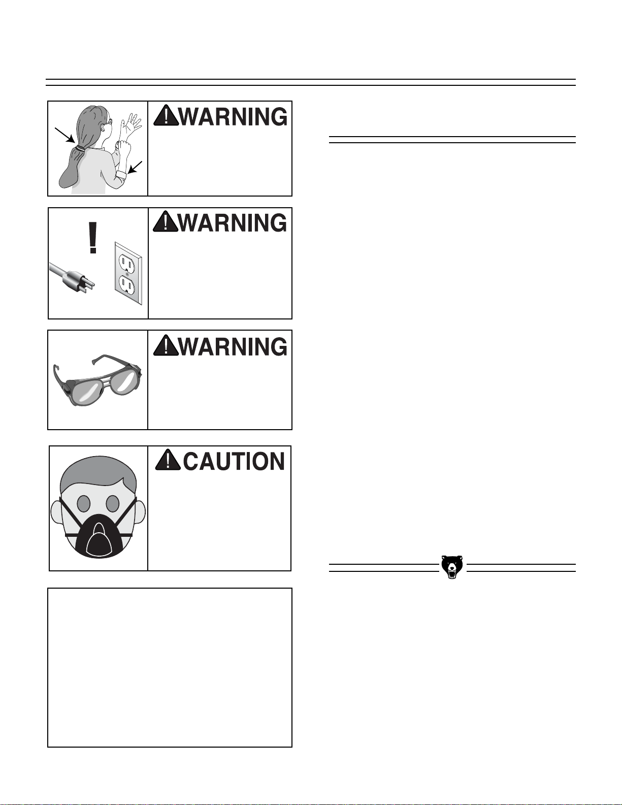
10. WEAR PROPER APPAREL. Do not wear
loose clothing, gloves, neckties, rings,
bracelets, or other jewelry which may get
caught in moving parts. Non-slip footwear
is recommended. Wear protective hair
covering to contain long hair.
11. ALWAYS USE SAFETY GLASSES. Also
use face or dust mask if cutting operation
is dusty. Everyday eyeglasses only have
impact resistant lenses, they are NOT
safety glasses.
12. SECURE WORK. Use clamps or a vise to
hold work when practical. It’s safer than
using your hand and frees both hands to
operate tool.
LENGTH
AMP RATING 25ft 50ft 100ft
0-6 18 16 16
7-10 18 16 14
11-12 16 16 14
13-16 14 12 12
17-20 12 12 10
21-30 10 10 No
Safety Instructions For Power Tools
13. DON’T OVERREACH. Keep proper foot-
ing and balance at all times.
14. MAINTAIN TOOLS WITH CARE. Keep
tools sharp and clean for best and safest
performance. Follow instructions for lubricating and changing accessories.
15. DISCONNECT TOOLS before servicing
and changing accessories, such as blades,
bits, cutters, and the like.
16. REDUCE THE RISK OF UNINTENTIONAL STARTING. Make sure switch is in off
position before plugging in.
17. USE RECOMMENDED ACCESSORIES.
Consult the owner’s manual for recommended accessories. The use of improper
accessories may cause risk of injury.
18. CHECK DAMAGED PARTS. Before fur-
ther use of the tool, a guard or other part
that is damaged should be carefully
checked to determine that it will operate
properly and perform its intended function.
Check for alignment of moving parts, binding of moving parts, breakage of parts,
mounting, and any other conditions that
may affect its operation. A guard or other
part that is damaged should be properly
repaired or replaced.
19. NEVER LEAVE TOOL RUNNING UNATTENDED. TURN POWER OFF. Don’t
leave tool until it comes to a complete stop.
Page 6
-4- Model G1019Z 14" Bandsaw
Additional Safety Instructions For Bandsaws
No list of safety guidelines can be complete. Every shop environment is different.
Always consider safety first, as it applies to
your individual working conditions. Use
this and other machinery with caution and
respect. Failure to do so could result in
serious personal injury, damage to equipment or poor work results.
7. ALWAYS FEED STOCK EVENLY AND
SMOOTHLY. Do not force or twist blade
while cutting, especially when sawing
small radii.
8. THIS MACHINE IS NOT DESIGNED TO
CUT METAL or other material except
wood.
9. BLADE SHOULD BE RUNNING AT FULL
SPEED before beginning a cut.
10. DO NOT MANUALLY STOP OR SLOW
BLADE after turning the saw off. Allow it to
come to a complete stop before you leave
it unattended.
11. ALL INSPECTIONS, ADJUSTMENTS,
AND MAINTENANCE ARE TO BE DONE
WITH THE POWER OFF and the plug
pulled from the outlet. Wait for all moving
parts to come to a complete stop.
12. HABITS – GOOD AND BAD – ARE HARD
TO BREAK. Develop good habits in your
shop and safety will become second
nature to you.
1. DO NOT OPERATE WITH DULL OR
BADLY WORN BLADES. Dull blades
require more effort to use and are difficult
to control. Inspect blades before each use.
2. NEVER POSITION FINGERS OR
THUMBS IN LINE WITH THE CUT.
Serious personal injury could occur.
3. DO NOT OPERATE THIS BANDSAW
WITHOUT WHEEL, PULLEY, AND
BLADE GUARDS IN PLACE.
4. WHEN REPLACING BLADES, make sure
teeth face down toward the table. The
force of the cut is always down. Make sure
the blade is properly tensioned.
5. CUTS SHOULD ALWAYS BE FULLY
SUPPORTED by the table or some type of
support fixture. Always support round stock
in a V-block.
6. DO NOT BACK WORKPIECE AWAY from
the blade while the saw is running. Plan
your cuts so you always cut out of the
wood. If you need to back the work out,
turn the bandsaw off and wait for the blade
to come to a complete stop. Do not twist or
put excessive stress on the blade while
backing work away.
Like all power tools, there is danger associated with bandsaws. Accidents are frequently caused by lack of familiarity or failure to pay attention. Use this tool with
respect and caution to lessen the possibility of operator injury. If normal safety precautions are overlooked or ignored, serious
personal injury may occur.
Page 7
Model G1019Z 14" Bandsaw -5-
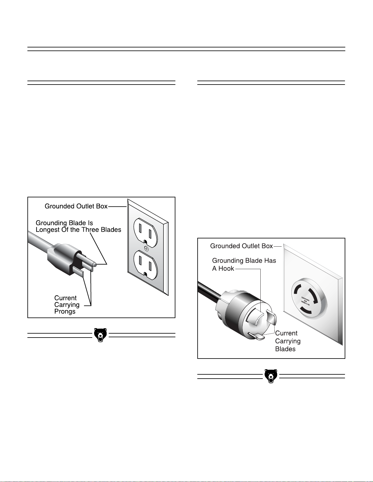
220V Operation
The motor supplied with the G1019Z can be operated at either 110V or 220V. The motor comes
prewired for 110V.
If converting to operate at 220V, a suitable 220V
plug must be wired in. Refer to the wiring diagram
insert supplied with this manual. When operating
at 220V, we recommend using a NEMA-style 6L-
15 plug and outlet. See Figure 2. Check the elec-
trical codes in your area for specifics on wiring
requirements.
Under normal use, the motor draws approximately 6 amps @ 220V. We recommend a 10 amp circuit breaker. This should be satisfactory for normal use while providing enough protection
against damage caused by power surges.
SECTION 2: CIRCUIT REQUIREMENTS
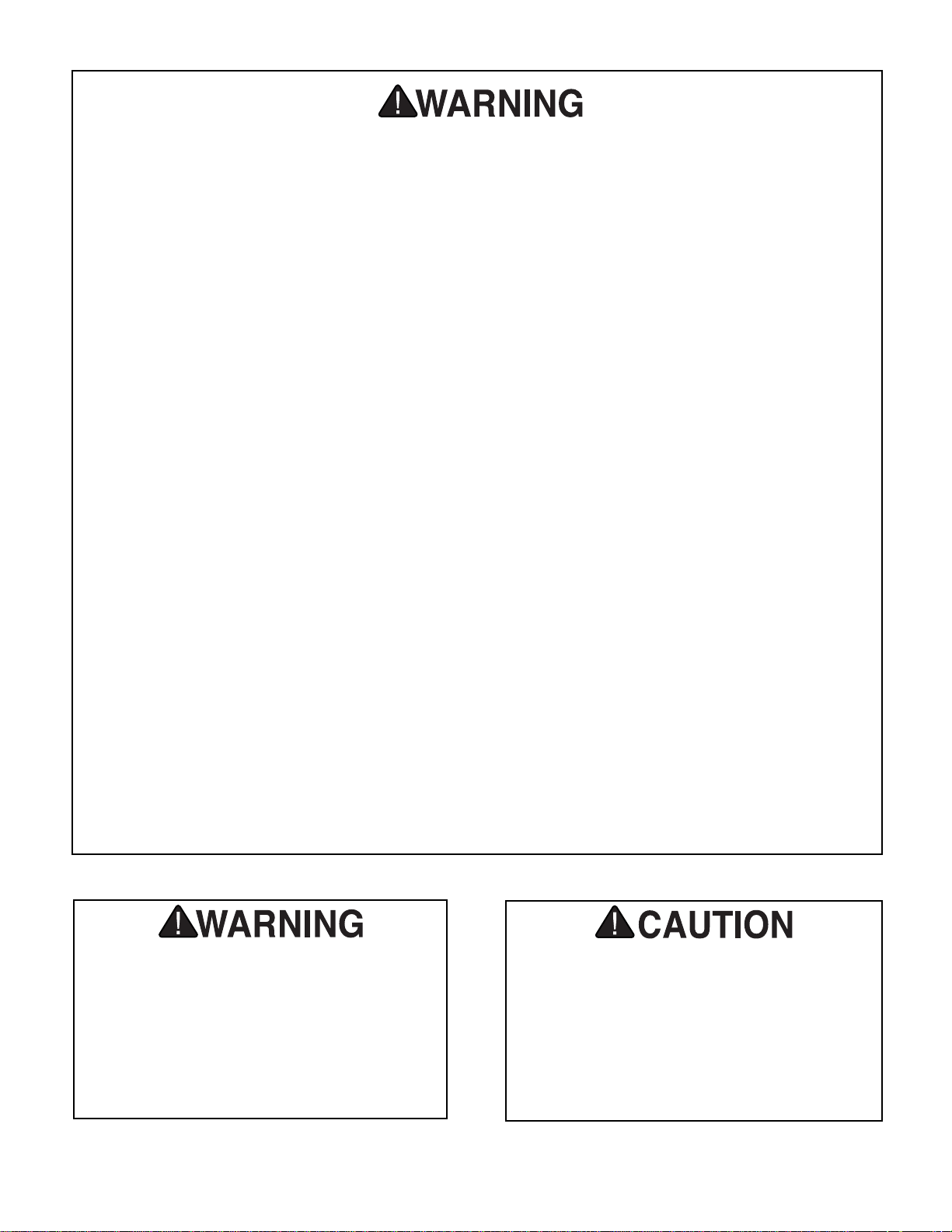
110V Operation
The G1019Z Bandsaw motor is prewired to oper-
ate at 110V. See Figure 1. Under normal 110V
use, the motor draws approximately 12 amps. We
recommend a 15 amp circuit breaker or a 15 amp
slow-blow fuse.
We also recommend that the circuit you use
should be dedicated, (i.e., the G1019Z should
provide the only draw from that circuit). If frequent
circuit failures occur when using the bandsaw,
contact our Service Department or your local
electrical contractor.
Figure 1. Typical 110V 3-prong plug and outlet.
Figure 2. Typical 220V 3-prong plug and outlet.
Page 8
Grounding
In the event of an electrical short, grounding provides a path of least resistance for electric current
to reduce the risk of electric shock. This tool is
equipped with an electric cord having an equipment-grounding conductor. The plug must be
plugged into a matching outlet that is properly
installed and grounded in accordance with all
local codes and ordinances.
Improper connections of the electrical-grounding
conductor can result in risk of electric shock. The
conductor with green or green and yellow striped
insulation is the electrical grounding conductor. If
repair or replacement of the electric cord or plug
is necessary, do not connect the equipment
grounding conductor to a live terminal.
-6- Model G1019Z 14" Bandsaw
Should it be necessary to use an extension cord,
make sure the cord is rated Hard Service (grade
S) or better. Refer to chart in the Safety
Instructions section to determine the minimum
gauge for the extension cord. The extension cord
must also contain a ground wire and plug pin.
Always repair or replace extension cords when
they become worn or damaged.
We do not recommend the use of extension cords
on 220V equipment. It is much better to arrange
the placement of your equipment and the installed
wiring to eliminate the need for extension cords.
Extension Cords
We have covered some basic electrical
requirements for the safe operation of your
Bandsaw. These requirements are not necessarily comprehensive. You must be sure
that your particular electrical configuration
complies with local and state codes. Ensure
compliance by checking with your local
municipality or a licensed electrician.
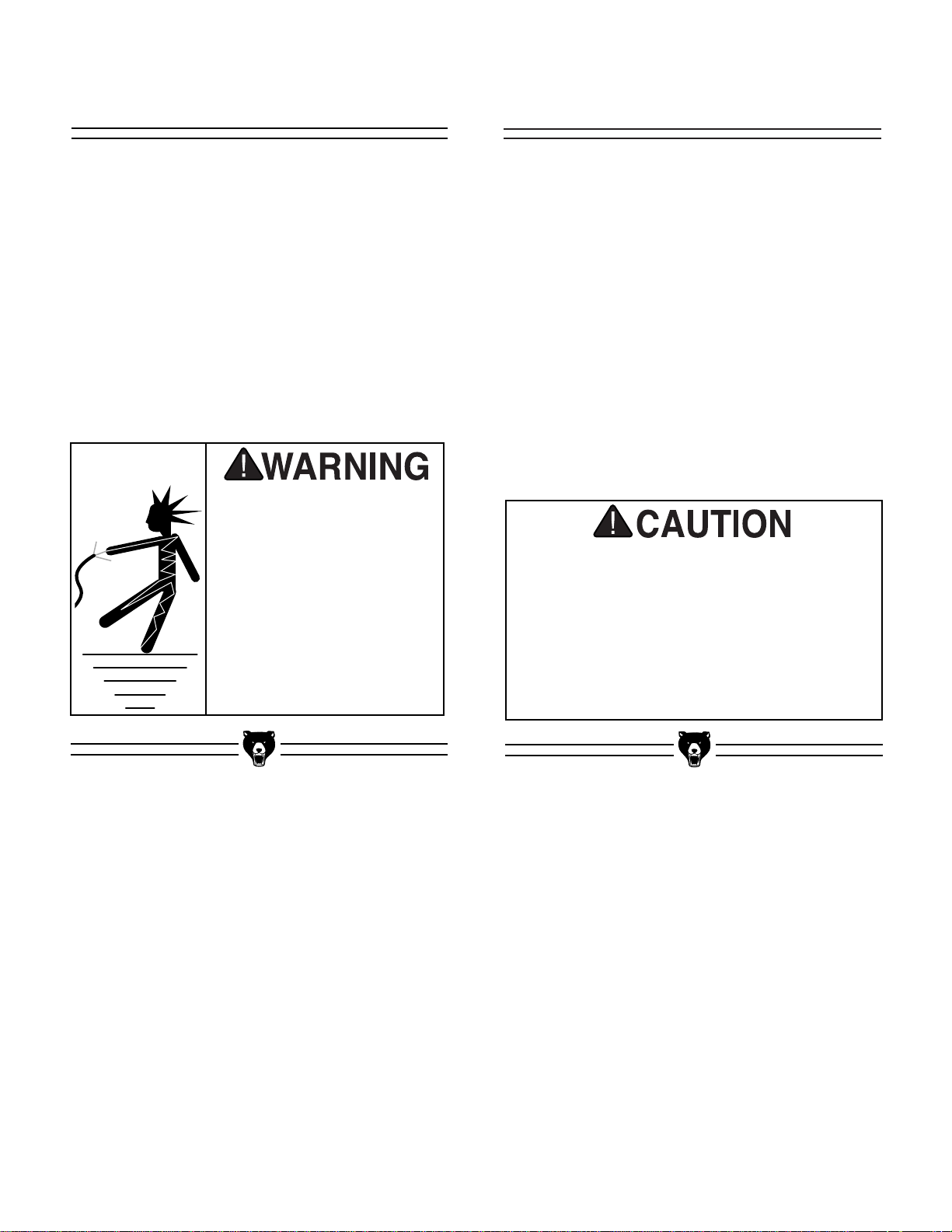
This equipment must be
grounded. Verify that any
existing electrical outlet
and circuit you intend to
plug into is actually
grounded. Under no circumstances should the
grounding pin from any
three-pronged plug be
removed. Serious injury
may occur.
Page 9

Model G1019Z 14" Bandsaw -7-
Grizzly Industrial, Inc. is proud to offer the Model
G1019Z 14" Bandsaw. The G1019Z is part of
Grizzly’s growing family of fine woodworking and
metalworking machinery. When used according
to the guidelines stated in this manual, you can
expect years of trouble-free, enjoyable operation,
and proof of Grizzly’s commitment to customer
satisfaction.
The Model G1019Z is intended for home and
medium-duty professional use. The G1019Z features cast iron construction for rigidity and
strength, a solid cast iron table, an open steel
stand, fence and miter gauge. A 2" dust port and
1
⁄2" blade are also included. The electrical package consists of a 3450 R.P.M., 1 H.P. capacitor
start motor, locking toggle switch and cord set. All
running parts utilize shielded ball bearings, which
require no lubrication for the life of the bearings.
We are also pleased to provide this manual with
the Model G1019Z. It was written to guide you
through assembly, review safety considerations,
and cover general operating procedures. It represents our effort to produce the best documentation possible. If you have any comments regarding this manual, please write to us at the address
below.
Grizzly Industrial, Inc.
C
/O Technical Documentation
P.O. Box 2069
Bellingham, WA 98227-2069
SECTION 3: INFORMATION
Above all else, we stand behind our machines.
We have an excellent service department at your
disposal should the need arise. If you have any
service questions or parts requests, please call or
write to us at the location listed below.
Grizzly Industrial, Inc.
2406 Reach Road
Williamsport, PA 17701
Phone:(570) 546-9663
Fax:(800) 438-5901
E-Mail: techsupport@grizzly.com
Web Site: www.grizzly.com
Address after fall 2001:
Grizzly Industrial, Inc.
1203 Lycoming Circle
Pennsdale, PA 17756
Commentary
The specifications, drawings, and photographs
illustrated in this manual represent the Model
G1019Z as supplied when the manual was prepared. However, owing to Grizzly’s policy of continuous improvement, changes may be made at
any time with no obligation on the part of Grizzly.
Whenever possible, though, we send manual
updates to all owners of a particular tool or
machine. Should you receive one, we urge you to
insert the new information with the old and keep it
for reference.
Read the manual before
assembly and operation.
Become familiar with
the machine and its
operation before beginning any work. Serious
personal injury may
result if safety or operational information is not
understood or followed.
Page 10
-8- Model G1019Z 14" Bandsaw
Unpacking
The Model G1019Z Bandsaw is shipped from the
manufacturer in a carefully packed carton. If you
discover the machine is damaged after you’ve
signed for delivery, please call Customer Service
immediately for advice.
Save the containers and all packing materials for
possible inspection by the carrier or their agent.
Otherwise filing a freight claim can be difficult.
Piece Inventory
Hardware Bag #1 Qty
Rubber Feet 4
Table Insert 1
Table Trunnion Knobs 2
Fender Washers
1
⁄4"3
Lock Washers
5
⁄16"3
Cap Screws
1
⁄4" - 20 x 1" 3
Key 5 x 5 x 25mm 1
Nut
3
⁄8" - 16 1
Bolt
3
⁄8" - 16 x 21⁄2"1
Setscrew
1
⁄4" - 20 x 1⁄4"1
Roll Pin 3 x 10mm 1
Allen
®
Wrench 3mm 1
Allen
®
Wrench 5mm 1
Hardware Bag #2 Qty
Cap Screws
1
⁄4" - 28 x 11⁄8"2
Fence Spacers 2
Carriage Bolts
5
⁄16" - 18 x 3⁄4"32
Nuts
5
⁄16" - 18 32
Nuts
3
⁄8" - 16 4
Flat Washers
3
⁄8"8
Flat Washers
5
⁄16"32
Bolts
3
⁄8" - 16 x 1" 4
In the event that any parts are missing, we will be
happy to replace them. Contact our Customer
Service number for assistance. If any non-proprietary parts such as nuts, bolts or washers are
missing, we will be happy to replace these too, but
for the sake of expediency, these items can be
obtained at your local hardware store.
After all the parts have been removed from the
carton, you should have:
• Stand Assembly
4 Stand Legs
1 Stand Top
2 Upper Stand Braces
2 Lower Stand Braces (Short)
2 Lower Stand Braces (Long)
• Motor
• Motor Pulley
• Bandsaw Unit
• Table
• Table Bracket
• Fence
• Fence Rail
• Fence Lock Knob
• Miter Gauge
When you are completely satisfied with the condition of your shipment, you should inventory its
parts.
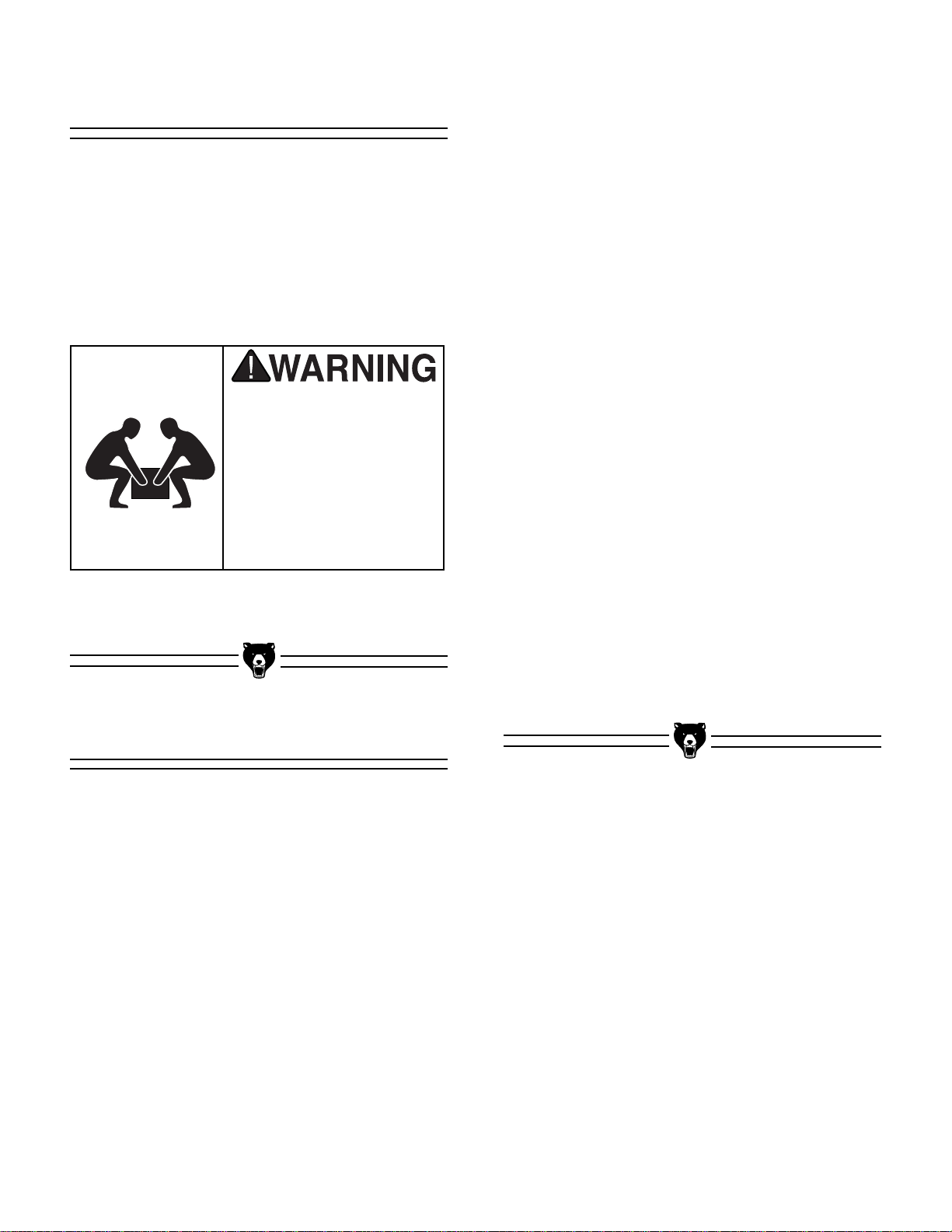
The Model G1019Z is a
heavy machine (165
lbs. shipping weight).
DO NOT over-exert
yourself while unpacking or moving your
machine—get assistance.
Page 11
Model G1019Z 14" Bandsaw -9-
Clean up Site Considerations
The unpainted surfaces are coated with a waxy oil
to protect them from corrosion during shipment.
Remove this protective coating with a solvent
cleaner or citrus-based degreaser such as
Grizzly’s G7895 Degreaser. Avoid chlorine-based
solvents as they may damage painted surfaces
should they come in contact. Always follow the
usage instructions on the product you choose for
clean up.
FLOOR LOAD
Your G1019Z Bandsaw represents a moderately
large weight load in a small footprint. Most commercial or home shop floors should be sufficient
to carry the weight of the G1019Z. If you question
the strength of your floor, you can opt to reinforce
it.
WORKING CLEARANCES
Working clearances can be thought of as the distances between machines and obstacles that
allow safe operation of every machine without limitation. Consider existing and anticipated machine
needs, size of material to be processed through
each machine, and space for auxiliary stands
and/or work tables. Also consider the relative
position of each machine to one another for efficient material handling. Be sure to allow yourself
sufficient room to safely run your machines in any
foreseeable operation.
LIGHTING AND OUTLETS
Lighting should be bright enough to eliminate
shadow and prevent eye strain. Electrical circuits
should be dedicated or large enough to handle
combined motor amp loads. Outlets should be
located near each machine so power or extension
cords are not obstructing high-traffic areas. Be
sure to observe local electrical codes for proper
installation of new lighting, outlets, or circuits.
Do not use gasoline or
other petroleum-based
solvents to clean with.
They have low flash
points which makes
them extremely flammable. A risk of explosion
and burning exists if
these products are
used. Serious personal
injury may occur.
Do not smoke while using
solvents. A risk of explosion or fire exists and may
result in serious personal
injury.
Many of the solvents
commonly used to clean
machinery can be toxic
when inhaled or ingested. Always work in wellventilated areas far from
potential ignition sources
when dealing with solvents. Use care when disposing of waste rags and
towels to be sure they do
not create fire or environmental hazards.
Make your shop “child safe.”
Ensure that your workplace
is inaccessible to children by
closing and locking all
entrances when you are
away. Never allow visitors in
your shop when assembling,
adjusting or operating equipment.
Page 12
-10- Model G1019Z 14" Bandsaw
SECTION 4: ASSEMBLY
Beginning Assembly
Most of your G1019Z Bandsaw has been assembled at the factory, but some parts must be
assembled or installed after delivery. We have
organized the assembly process into steps.
Please follow along in the order presented here.
TOOLS REQUIRED: You will need an adjustable
square, 10mm, 12mm and 14mm open end
wrenches and a Phillips
®
and regular screwdriver.
Keep clothing rolled up
and out of the way of
machinery and keep
hair pulled back.
Wear safety glasses during the entire assembly
process. Failure to comply may result in serious
personal injury.
Some metal parts may
have sharp edges on
them after they are
formed. Please examine
the edges of all metal
parts before handling
them. Failure to do so
could result in injury.
Disconnect power to the
machine when performing any maintenance or
assembly. Failure to do
this may result in serious
personal injury.
Page 13
Model G1019Z 14" Bandsaw -11-
Stand
To begin stand assembly, keep all the stand parts
within easy reach. To ease assembly, build the
stand upside down on a bench and then place it
upright on the floor.
1. Place the stand top upside down on your
bench.
2. Attach each of the four legs to the stand top
with carriage bolts, washers and nuts provided. Do not over tighten. The legs attach
to the outside of the stand top. See Figure
3.
3. Position the two upper stand braces and fin-
ish installing the carriage bolts. Do not over
tighten.
4. Attach each of the four braces to the stand
legs with carriage bolts, washers and nuts
provided. Do not over tighten. The braces
attach to the inside of the legs. See Figure 3.
Figure 3. Completed stand assembly.
5. Press one
5
⁄16"-18 x 1⁄2" hex bolt into each
rubber foot. Use the washers and nuts supplied to attach a rubber foot onto each of the
stand legs.
6. Flip the stand right side up and place on the
floor. Check to see if the stand is symmetrical from two adjacent sides. Adjust if necessary and tighten all nuts.
Page 14
-12- Model G1019Z 14" Bandsaw
Motor
The motor attaches to the back of the lower bandsaw unit. To install the motor:
1. Slide the motor pulley onto the motor shaft
so the larger diameter pulley is closest to
the motor. Line up the keyways and slide
the key into the keyway. Insert the setscrew
and tighten. Pulley alignment will be done in
Step 5.
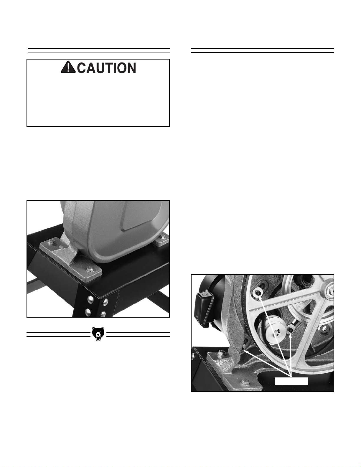
2. Support the motor and insert the motor pul-
ley through the hole in the back of the bandsaw unit.
3. Align the mounting holes and attach each of
three cap screws, lock washers and fender
washers through the bandsaw unit and into
the motor. Leave the cap screws loose for
motor adjustment. See Figure 5.
4. Slip the V-belt onto the grooves of the wheel
and motor pulleys. Remember, this is a two
speed bandsaw. Be sure that the pulleys
you choose are aligned. Do not try to force
the V-belt onto non-aligned grooves. See
“Changing Speeds” in the Operations section to select the proper speed.
Figure 5. Cap screws securing motor.
Cap Screws
1. Place the bandsaw on the stand and align
the four holes in the base over the four
mounting holes in the stand.
2. Secure the bandsaw base to the stand with
the four hex bolts, nuts and washers provid-
ed. See Figure 4.
Figure 4. Bandsaw mounted to stand.
Bandsaw Unit
This bandsaw is relatively heavy and awkward to handle. We strongly recommend
that you get assistance. The bandsaw unit
is also very unstable until it is permanently
mounted to the stand. Use care so the
bandsaw unit does not tip.
Page 15
Model G1019Z 14" Bandsaw -13-
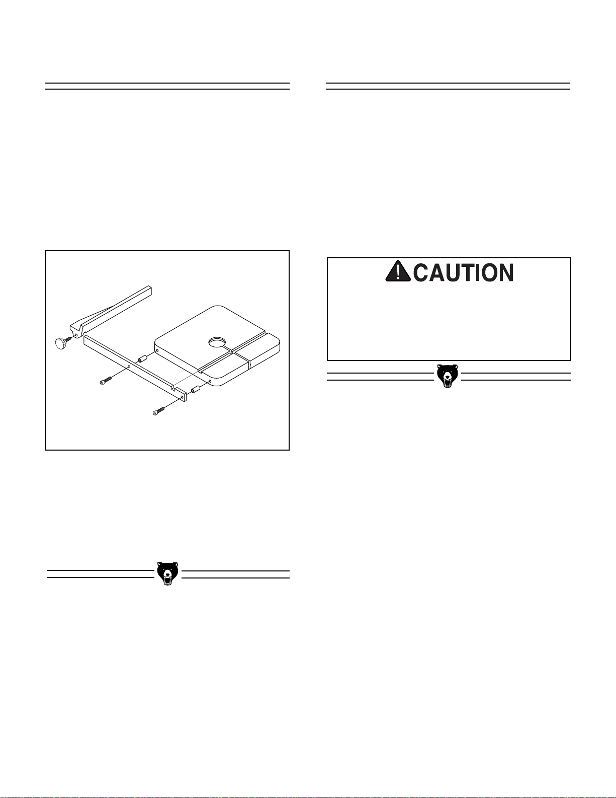
Figure 7b. Connecting switch to motor.
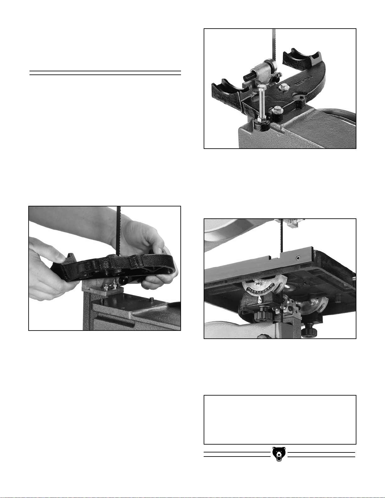
The switch is premounted on the bandsaw unit
and features a lock-out key. To lock-out the
switch, move the switch to the off position and
then pull out the key. See Figure 7a. The band-
saw cannot be turned on without first inserting the
key back into the switch.
Switch
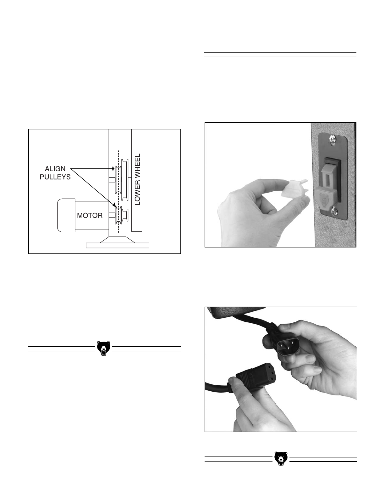
5. Check for proper pulley alignment by plac-
ing a straightedge on the outside edge of
the upper pulley so that it overlaps the
motor pulley. If the straightedge touches
both pulleys evenly, the pulleys are aligned.
If the straightedge does not touch both pulleys evenly, the pulleys are not aligned.
Loosen one or both of the pulley setscrews
on their shafts and slide the pulleys toward
alignment. Remember to retighten the
setscrews when finished. See Figure 6.
Figure 6. Schematic of proper pulley alignment.
Figure 7a. Switch lock-out key.
6. Adjust V-Belt tension by sliding the motor
along the mounting slots. Proper tension is
achieved when the belt can be deflected
roughly
1
/2" with moderate finger pressure.
7. Tighten the socket head cap screws
securely. Recheck belt tension and pulley
alignment.
To connect the switch to the motor:
1. Plug the male end into the female end as
shown in Figure 7b.
Page 16
-14- Model G1019Z 14" Bandsaw
6. Secure the table to the support bracket by
securing the two trunnion knobs onto the
trunnion bolts. Remember to position the
table so that the miter slot is to the right of
the blade as you face the front of the band-
saw. See Figure 10.
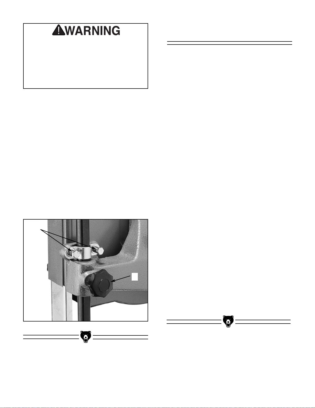
Figure 9. Stop bolt assembled on bracket.
Figure 10. Positioning table on support bracket.
7. Place the table insert in the table top and
place the tapered pin so it fits snugly in the
hole on the side of the table. Do not use
excessive force.
NOTICE
The tapered table pin must be in position in
the table when operating the bandsaw. This
maintains the table surface flush with no edge
for the workpiece to catch on.
Table and Table
Support Bracket
The bandsaw table secures to the table trunnions.
The trunnions mount to the table support bracket
and the table support bracket mounts to the bandsaw unit. The trunnions are premounted to the
table. To mount the bandsaw table:
1. Remove the two table support bracket
mounting bolts from the bandsaw body.
2. Insert the alignment pin that positions the
table support bracket to the bandsaw body.
Place the table bracket on the body over the
alignment pin and secure it to the bandsaw
with the two bolts. See Figure 8.
Figure 8. Aligning bracket on the pins.
3. Thread the locknut onto the table stop bolt
and thread the bolt into the table support
bracket. See Figure 9. Bolt adjustments are
covered in the “Table Adjustments” section
beginning on page 18.
4. Remove tapered pin from the table.
5. Slip the table past the blade through the
table slot, rotate the table 90°, and set the
table trunnions onto the bracket. Make sure
the trunnion bolts drop through the support
bracket.
Page 17
Model G1019Z 14" Bandsaw -15-
Fence
When installing the fence, notice that the front
edge of the table has two threaded holes. These
holes accept the round spacers and socket head
cap screws that attach the fence rail to the table.
1. Secure the fence rail to the table with the
two socket head cap screws and spacers
provided. Ensure that the slot in the rail
lines up with the miter gauge slot in the
table. See Figure 11.
Figure 11. Fence assembly schematic.
2. Mount the fence on the left side of the blade
by setting the fence onto the table and rail.
3. Insert and tighten the fence locking knob to
secure the fence at the desired distance
from the blade.
A
1
⁄2" blade is included with the bandsaw and is
already installed on the machine. Refer to “Blade
Tensioning” and “Blade Tracking” on pages 16
and 17 before starting the machine. Also, the
Operations section contains instructions on
selecting and changing blades.
This concludes the assembly process. Please DO
NOT operate this saw until you have read this
entire manual.
Blades
Do not operate this Bandsaw until you have
completed the adjustments noted in the
next section and have reviewed all safety
information. Serious personal injury may
result.
Page 18

-16- Model G1019Z 14" Bandsaw
Figure 13. Blade tension and tracking controls.
F
G
General
SECTION 5: ADJUSTMENTS
General control and adjustment locations are
shown in Figures 12, 13 & 14 and are described
below.
A. These two knobs secure the upper and
lower wheel covers. The covers should only
be opened to change a blade or make an
adjustment to blade tracking. Always dis-
connect power before opening.
B. This is the paddle switch that controls the
motor. To turn the motor on, flip the paddle
to the up position. To turn the motor off,
push the paddle to the down position.
C. This knob locks the rip fence in position.
D. These trunnion knobs are used to lock the
table in position.
E. The miter gauge slides in the milled groove
in the table and can be set at 45° left and
right. Use the miter gauge for crosscutting
and miter-cutting.
Now, direct your attention to the controls located
around the backside of the upper cover of the
saw. See Figure 13.
F. This knob is used to control blade tension.
Turning clockwise increases tension;
counter-clockwise decreases tension.
G. This knob controls blade tracking. Note that
the knob has a locknut to lock tracking in
place.
Figure 12. Location of controls.
A
B
C
D
E
Keep clothing rolled up
and out of the way of
machinery and keep
hair pulled back.
Wear safety glasses during the entire adjustment
process. Failure to comply may result in serious
personal injury.
Disconnect power to the
machine when performing any maintenance or
assembly. Failure to do
this may result in serious
personal injury.
Page 19
Model G1019Z 14" Bandsaw -17-
Blade Tension
Figure 14. Location of blade guide controls.
H
I
The controls for the blade guide are shown in
Figure 14. The blade guide should always be
positioned so there is minimal space between the
guide and the top of the workpiece.
H. This knob locks the upper blade guide
assembly in position. The upper guide
should be adjusted to within
1
⁄4" of the workpiece for optimum blade support. Do not
operate bandsaw without locking the guide
post knob.
I. These spring-loaded bolts apply pressure
against the U-clamp to prevent the guide
post from dropping when the upper blade
guide knob is loosened.
Proper blade tension is important for optimum
bandsaw performance. See Figure 13 for band-
saw tension controls. To increase blade tension,
turn the blade tension knob clockwise. To reduce
blade tension, turn the blade tension knob
counter-clockwise.
Since a variety of blades will work well with this
saw, final blade tension ultimately depends on the
type and size of blade you use. Thin blades
require less tension than wide blades. Too much
tension will result in blade breakage.
Do not make adjustments while the bandsaw is running. Ensure that the switch is off,
power is disconnected, and moving parts
have stopped before making adjustments.
Check adjustments while power is still disconnected by manually turning the bandsaw
wheel by hand.
A properly tensioned blade will track the cutting
line accurately and the cut will be smoother.
Proper blade tension can best be achieved by
determining the amount of blade deflection:
1. Ensure that the power is off and the saw is
unplugged. Raise the upper guide assembly all the way and lock in place.
2. Press, with moderate pressure, on the face
of the blade with your thumb.
3. Turn the tensioning knob to adjust the
amount of tension. The blade should deflect
about
1
/4".
If the tension seems correct, make all of the other
adjustments to the saw and test run it. If the blade
is not cutting properly, the tension may be incorrect and readjustment may be needed.
Remember to reduce the blade tension when the
bandsaw is not in use, this will help prevent premature breakage of the blade and deformation of
the rubber tires.
Page 20

-18- Model G1019Z 14" Bandsaw
Figure 15. Upper blade guide assembly.
Blade Tracking
The bandsaw blade is dangerously sharp.
Use extreme caution when working near the
saw blade. Failure to exercise care could
result in severe injury.
Whenever changing a blade or adjusting tension
and tracking, the upper and lower blade support
bearings and guide blocks must be re-adjusted.
Always adjust the assemblies away from the
blade before installing a new blade or making
blade tracking adjustments. After blade tension
and tracking are set correctly, re-adjust the upper
and lower support bearings and guide block
assemblies into position. See Figure 15 for upper
blade guide and Figure 16 for lower blade guide.
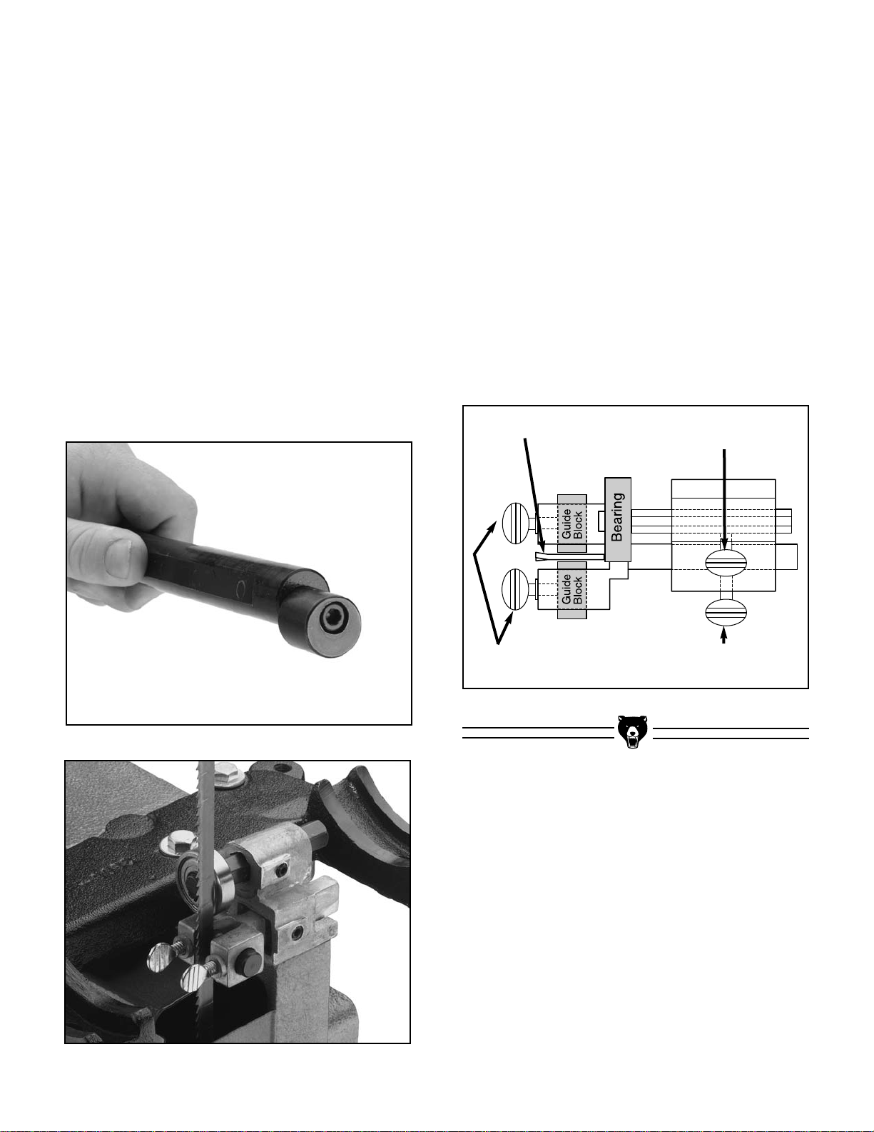
Support Bearings
The support bearings back-up the blade during
the sawing operation. To adjust the support bearings, loosen the thumbscrews securing the sup-
port bearing shafts. See Figure 17. Adjust the
shafts in or out so that the upper and lower support bearings are within
1
/64" of the back edge of
the blade. Retighten the thumbscrews.
Blade Guides
The blade should track so the body of the blade is
centered on the upper wheel and tire. The rubber
tire is slightly crowned in the middle which helps
keep the blade centered and avoids having the
teeth of the blade come in contact with the tire
material. See Figure 13 for bandsaw tracking
controls.
To adjust blade tracking:
1. Disconnect the bandsaw from the power
source.
2. Adjust the upper and lower guide blocks
and support bearings away from the blade.
3. Loosen the locknut on the tracking control
knob and turn the knob clockwise or
counter-clockwise while turning the upper
wheel by hand. When turning the wheel by
hand, ensure that there are no sharp
edges to cut your hand.
4. Turn the upper wheel and tracking knob
until the blade is centered on the upper
wheel and tire. Turn the wheel at least three
more full turns to ensure that the blade is
tracking in its final position.
5. Retighten the locknut and double check
blade tracking.
6. Install the upper wheel cover.
Page 21
Model G1019Z 14" Bandsaw -19-
Guide Blocks
For optimum support, the guide block assemblies
should be adjusted so they are just behind the
gullet line (the hollow points) of the blade. To
adjust the guide block assemblies, loosen the
thumbscrews securing the guide block yoke
assemblies. Move in or out in relation to the blade
gullets. Once adjusted, retighten the thumbscrew.
Now adjust the guide blocks. Loosen the guide
block thumbscrews and adjust each block so it is
about 0.004" from the blade. This is about the
same thickness as a piece of typing paper.
Retighten the thumbscrews and turn the upper
wheel by hand through a complete revolution of
the blade length to ensure that the blade weld
passes through the guide blocks unhindered.
Figure 17. Blade guide adjustments.
Support Bearing
Adjustment
Blade
Guide Block Lateral
Adjustment
Guide Block Extension
Adjustment
Figure 16. Lower blade guide assembly.
Figure 15A. Eccentric guide post.
Eccentric Guide Post
There is an eccentric on the lower end of the
guide post where the the guide assembly attaches. This is held to the post by a setscrew and can
be loosened and tightened with an Allen
®
wrench.
Figure 15A.
The eccentric allows the upper blade guide
assembly to be moved to accommodate various
blade sizes and wheel configurations.
Loosen the knob on the guide post. Rotate the
guide block assembly on the guide post so the
blade is directly in the center of the guide block
legs. Retighten the knob and make sure the
assembly didn’t move. If needed, adjust the
eccentric on the post to make the assembly
accommodate the blade.
Page 22
-20- Model G1019Z 14" Bandsaw
Table Adjustments
The bandsaw table will tilt left 10° and right 45°
from horizontal. When tilting the table to the right,
the positive stop adjusting bolt automatically
indexes the table perpendicular to the blade.
To tilt the table to the right:
1. Loosen the two trunnion knobs below the
table trunnions. See Figure 18 for location.
2. Position the table to the desired angle.
Refer to the angle gauge on the front table
support trunnion.
3. Tighten the trunnion knobs.
Figure 18. Table tilt trunnion knobs.
Figure 19. Table tilted left.
To tilt the table to the left:
1. Loosen the two trunnion knobs below the
table trunnions.
2. Tilt the table to the right enough to gain
clearance to the positive stop bolt. Loosen
the lock nut, then remove the positive stop
bolt.
3. The table will now tilt left to approximately
10°. See Figure 19.
4. When the left tilt operation is complete, rein-
stall the positive stop bolt.
Trunnion Knobs
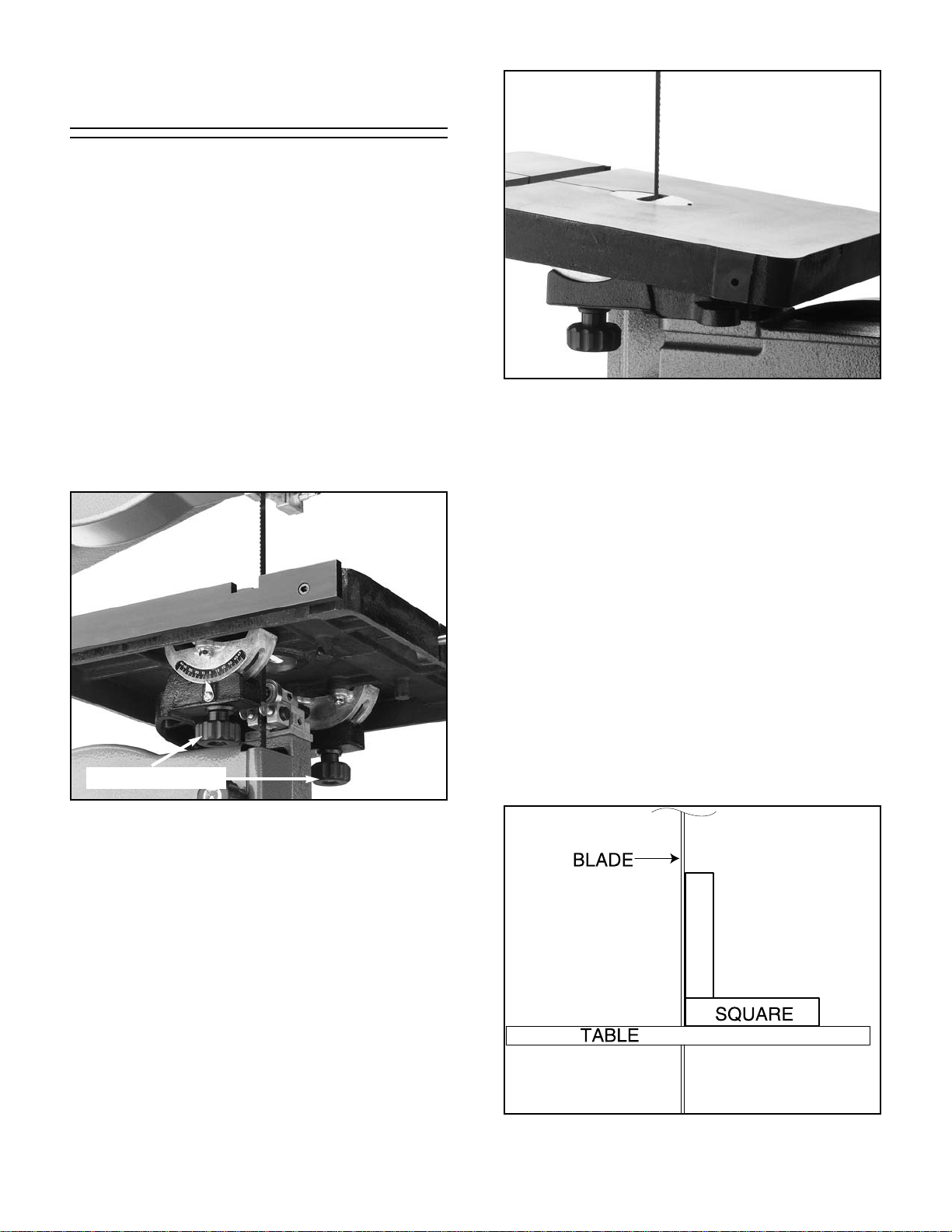
To adjust the positive stop so the table will be perpendicular (90°) to the blade:
1. Loosen two trunnion knobs and the locknut
securing the positive stop adjusting bolt.
2. Raise the upper blade guide assembly and
place a 6" adjustable square or try-square
on the table against the blade. See Figure
20. Adjust the positive stop adjusting bolt so
that the table is positioned at a 90° angle to
the blade.
3. Secure the trunnion knobs and lock the pos-
itive adjusting bolt by tightening the locknut.
Ensure that the bolt does not turn while
tightening the locknut. Set the angle pointer
to zero for future reference.
Figure 20. Squaring table to blade.
Page 23

Model G1019Z 14" Bandsaw -21-
Blade Lead
Blade lead occurs when you are attempting a
straight cut and the blade wanders to one side or
the other. This usually happens (1) if the blade
tension isn’t correct, (2) if the teeth are dull on one
side, or (3) if the teeth are heavier on one side of
the blade than the other.
If you don’t have time to switch blades or readjust
your bandsaw, you can temporarily compensate
for blade lead by slightly rotating your table. To do
this, rotate the table to match the angle that your
blade is leading. Your purpose in doing this is to
“trick” your bandsaw into cutting straight.
If you are having blade lead problems with your
miter gauge, do the same thing by slightly rotating
your table so the miter slot matches the angle that
the blade is leading.
Figure 21. Squaring table to blade.
Table
Miter Slot
Table Insert
The table should also be 90° to the back of the
blade. If the table is not perpendicular to the back
of the blade, shim the table in the desired direction with washers. Remove the trunnion bolts and
add washers between the table and trunnion so
the table tilts in the desired direction. Electrical
washers are very thin and will allow fine adjustment.
The table can be shifted side to side to properly
align the miter slot and the blade:
1. Loosen the 6 trunnion bolts underneath the
table.
2. Use the largest width blade available
installed in the machine. Lay a straightedge
along side the blade and inspect it closely to
make sure it is parallel to the blade. Make
sure there is no deflection of the blade from
the straightedge. Measure the distance
between the edge of the miter gauge slot
and the straightedge at points A and B. See
Figure 21. Distance A should be approximately equal to distance B. Adjust the table
slightly until these distances are equal.
3. Secure the table and ensure that unwanted
shifting did not occur during retightening.
After all adjustments are made, cut a test
piece of wood using the miter gauge and
measure to see if the cut was square. If it
wasn’t, adjust the table accordingly until you
can cut a test piece of wood square.
Page 24
-22- Model G1019Z 14" Bandsaw
Fence operation is controlled by the threaded
knob located on the front of the fence. The knob,
when screwed tight, locks the fence to the front
rail. To change the fence position, loosen the
knob and slide the fence along the rail. Use a tape
measure or ruler to position the fence from the
blade.
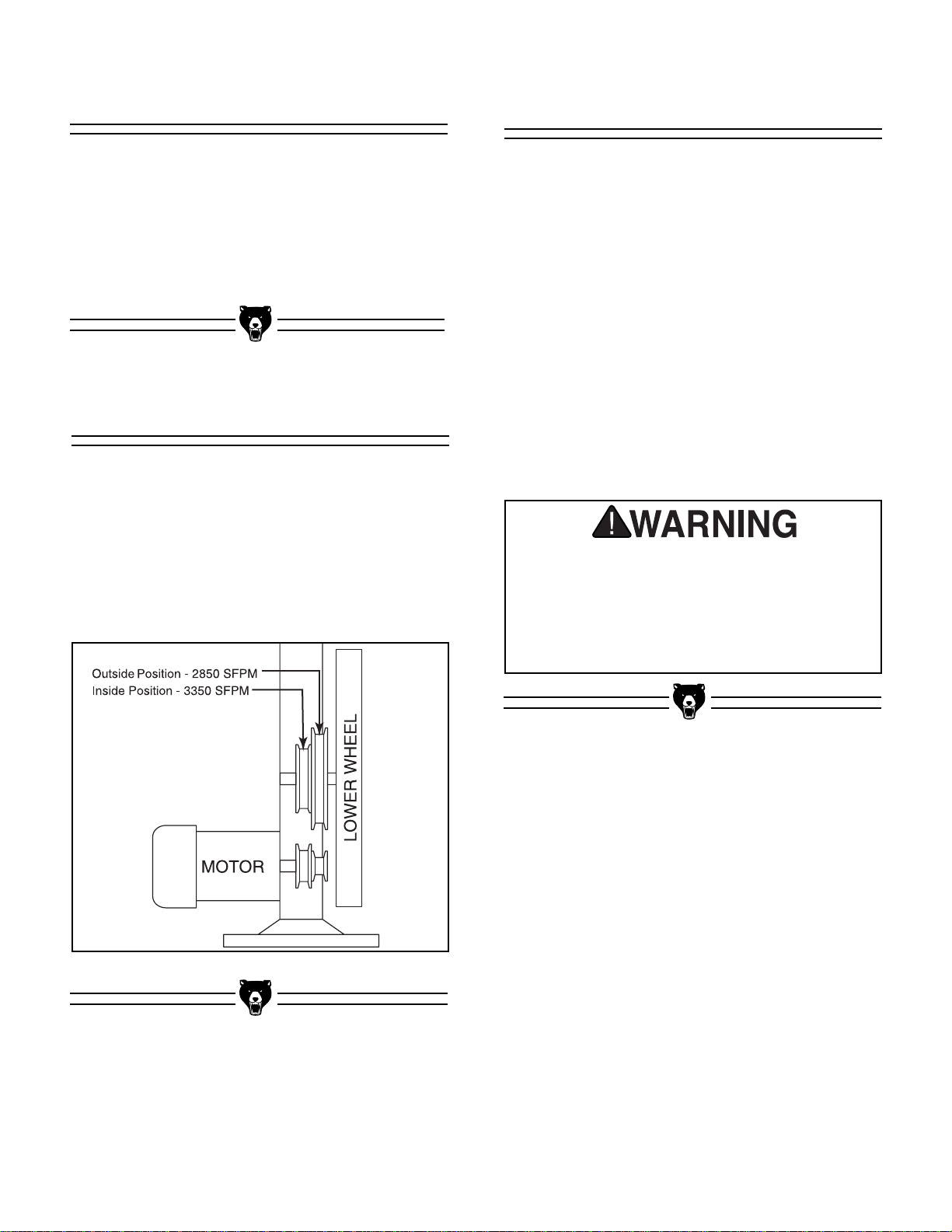
Loosen the motor mounting bolts and move the
motor accordingly to slacken the V-Belt. It should
now be easy to move the belt onto the pulleys of
choice. Adjust belt tension and check the alignment according to the instructions in the
Adjustments Section. Refer to Figure 22 to deter-
mine which pulley pair is required for the desired
blade speed.
Speed Changes
Fence Adjustment
Figure 22. Selecting pulleys for desired blade speed.
Once assembly is complete, adjustments are
done to your satisfaction and tools are safely put
away, you are ready to test run the machine.
Turn on the power supply at the main panel.
Press the switch in the START position. Make
sure that your finger is poised on the switch to
press in the STOP position, just in case there’s a
problem. The bandsaw should run smoothly, with
little or no vibration or rubbing noises. Strange or
unnatural noises should be investigated and corrected before operating the machine further.
If you cannot easily locate the source of an
unusual noise or vibration, contact our Service
Department for help.
Test Run
DO NOT attempt to investigate or adjust the
machine while it is running. Wait until the
machine is turned off, unplugged and all
working parts have come to a stop before
you do anything! Serious personal injury
will result.
Page 25
Model G1019Z 14" Bandsaw -23-
SECTION 6: OPERATIONS
There are many interrelated adjustment points to
consider when operating this type of saw.
Therefore, cutting results can be somewhat
unpredictable if some or all of the crucial adjustments are neglected. Here are a few simple
things you can do to increase the predictability of
your bandsaw’s performance:
1. Always use a sharp, high-quality blade.
Although you might save a few dollars initially, buying a cheap blade will give you
cheap results. As a rule, spending more
now will save you money later.
2. Use the right blade for the job. Resawing
with a
1
/8" blade or doing scrollwork with a
3
/4" blade are extreme examples of using
the wrong blade for the job.
3. Allow the saw to cut. Don’t force the work-
piece into the blade. When cutting curves or
irregular shapes, remember that while
negotiating a curve, the blade should still be
cutting the wood. Simply turning the workpiece will only bind the blade and could
cause it to break.
4. Maintain your bandsaw in top condition.
See Section 7 of this manual for maintenance procedures.
General
Keep clothing rolled up
and out of the way of
machinery and keep
hair pulled back.
Wear safety glasses during all operations on the
shaper. Failure to comply may result in serious
personal injury.
Always wear a dust
mask when operating
the bandsaw. Using this
machine produces sawdust which may cause
allergic reactions or respiratory problems.
NOTICE
The following section was designed to give
instructions on the basic operations of this
bandsaw. However, it is in no way comprehensive of every bandsaw application. WE
STRONGLY RECOMMEND that you read
books, trade magazines, or get formal training to maximize the potential of your
shaper. There are many different jigs that
can be built to increase safety, accuracy,
and types of cuts.
Disconnect power to the
machine when performing any maintenance or
assembly. Failure to do
this may result in serious
personal injury.
Page 26

-24- Model G1019Z 14" Bandsaw
When removing or installing blades, make sure
the power is disconnected and moving parts have
come to a complete stop.
To remove the blade:
1. Back guide block assemblies and support
bearings away from the blade and raise the
guide post up and away from the table.
2. Release blade tension by turning the blade
tension knob counter-clockwise.
3. Remove table insert and tapered table pin.
4. Remove top and bottom wheel covers.
5. Loosen the two blade guard mounting bolts
and slide the guard off of the mounting
studs.
6. Pull blade straight off the wheels, rotate 90°
and feed along the table through the table
slot.
To install the blade:
1. Hold blade in both hands so the teeth of the
blade in your right hand are pointing down.
2. Feed blade into the slot in the table. Turn
the blade 90° and position over the top and
bottom wheels. The teeth of the blade must
be pointing down toward the table.
3. Apply tension to the blade by turning the
tension control knob. Rotate the upper
wheel slowly by hand as tension is applied
to allow the blade to center itself on the
wheel. Adjust tracking if needed. See
“Blade Tension” and “Blade Tracking” in
Section 5 for details.
4. Re-adjust upper and lower blade guides
and support bearings as stated in the
Adjustment section.
Changing Blades
A bandsaw blade is a delicate piece of steel that
is subjected to tremendous strain. Be sure you
use quality blades of the proper width for the various types of cutting operations.
Always use the widest blade possible for the
workpiece you are cutting. Use narrow blades
only for sawing small, abrupt curves and for fine,
delicate work. Bandsaw blades can be purchased
welded, set and sharpened ready-for-use from
most saw shops. We also supply bandsaw blades
in widths of
1
/8", 3⁄16", 1/4", 3/8", 1/2", and 3/4", for this
saw. Please refer to our current catalog for prices
and ordering information.
Always use good quality saw blades that are
sharp and choose the right blade for the job.
Using a dull or poor quality blade, or the wrong
size or type, often produces unsatisfactory results
Many conditions may cause blade breakage.
Breakage is, in some cases, unavoidable, since it
is the natural result of the peculiar stresses to
which bandsaw blades are subjected. Blade
breakage is also due to avoidable causes.
Avoidable breakage is most often the result of
poor care or judgement on the part of the operator. The most common causes of blade breakage
are: (1) faulty alignment and adjustment of the
guides; (2) forcing or twisting a wide blade around
a tight curve or short radius; (3) feeding too fast;
(4) tooth dullness or absence of sufficient set; (5)
excessive blade tension; (6) upper blade guide
assembly set too high above the workpiece; (7)
using a blade with a lumpy or improperly finished
weld; and (8), continuously running the bandsaw
when not in use.
The Grizzly G1019Z 14" Bandsaw uses 98"
blades.
Blade Information
Page 27

Model G1019Z 14" Bandsaw -25-
Ripping is the process of cutting a board into two
or more thinner boards, generally in a direction
along its length. The maximum board width that
can be ripped is limited by the distance between
the blade and the support column. Maximum cutting width for this bandsaw is 14
1
⁄4".
The important consideration when ripping is blade
selection. Generally, the wider the blade, the better. In most applications, a hook or skip tooth style
will be sufficient. Also, since most ripped lumber
will be planed or sanded smooth, you can choose
blades with fewer teeth-per-inch. While blades
with fewer teeth-per-inch produce rougher cuts,
these types of blades offer larger gullet capacities
for clearing sawdust, produce less heat, and yield
more horsepower per tooth.
To perform ripping operations:
1. The bandsaw must be adjusted correctly.
See “Blade Tension” and “Blade Tracking”
in Section 5.
2. The table must be square to the blade. See
“Table Adjustment” in Section 5.
3. Use the widest blade available. The blade
must also be in good condition.
4. Use a fence to guide work.
5. Draw a reference line on the edge of the
board.
6. Support ends of the board if necessary.
7. Feed work slowly and evenly.
Ripping
Figure 23. Side and front views of a standard
bandsaw blade.
Gullet Line
Gullet
Tooth
Tooth
Gullet
Blade Set
The bandsaw blade is dangerously sharp.
Use extreme caution when working near the
saw blade. Failure to exercise care could
result in severe injury.
5. Install the table taper pin and table insert.
6. Install the blade guard.
7. Close the top and bottom covers.
Page 28

-26- Model G1019Z 14" Bandsaw
When cutting curves, simultaneously feed and
turn the stock carefully so that the blade follows
the layout line without being twisted. If a curve is
so abrupt that it is necessary to repeatedly back
up and cut a new kerf, use either a narrower blade
or a blade with more set.
Always make short cuts first, then proceed to the
longer cuts. Relief cuts will also reduce the
chance that the blade will be pinched or twisted.
Relief cuts are cuts made through the waste portion of the workpiece and are stopped at the layout line. As you cut along the layout line, waste
wood is released from the workpiece, alleviating
any pressure on the back of the blade. Relief cuts
also make backing the workpiece out easier, if
needed. Figure 24 lists blade widths and corre-
sponding minimum radii each blade will cut.
BLADE WIDTH
1
/8"
3
/16"
1
/4"
3
/8"
1
/2"
5
/8"
3
/4"
MINIMUM RADII
3
/16"
5
/16"
5
/8"
1
1
/2"
2
1
/2"
4"
5
1
/2"
Figure 24. Minimum circle radius vs. blade size.
Cutting CurvesStacked Cuts
One of the benefits of a bandsaw is its ability to
cut multiple copies of a particular shape by stacking a number of workpieces together.
Before making stacked cuts, it is essential to
ensure that both the table and the blade are properly adjusted to 90°. Otherwise, any error will be
compounded with each piece cut from the top to
the bottom of the stack.
To complete a stacked cut:
1. Align your pieces from top to bottom to
ensure that each piece has adequate scrap
to provide a clean, unhampered cut.
2. Using brads in the waste portion of each
piece, secure all the pieces together.
3. Lay out the shape you intend to cut on the
face of the top piece.
4. Make relief cuts perpendicular to the outline
of your intended shape in areas where
changes in blade direction could pinch the
blade against the wood.
5. Cut the stack as though you were cutting a
single piece. Follow your layout line with the
blade kerf on the waste side of your line.
Page 29

Model G1019Z 14" Bandsaw -27-
To resaw lumber, follow the procedure below:
1. The blade must be adjusted correctly and
the table must be square to the blade. See
Section 5.
2. Use the widest blade that will fit this saw
(
3
/4"). The blade must also be in good con-
dition.
3. Use the fence or a pivot block to guide the
work. If using a pivot block, clamp the block
to the table next to the fence at the desired
distance from the blade and mark the line of
cut on the workpiece. Follow the mark during cutting while using the pivot block as a
guide.
4. Feed work slowly and evenly.
When using a fence to guide the board, the actual line of cut may not always be parallel to the
fence. In fact, most bandsaw blades will not cut
exactly parallel to the fence. There are usually a
number of reasons for this: teeth are set heavier
on one side than the other, teeth are dull on one
side, or blade tension is too tight or too loose.
If the blade wanders off the line of cut when using
the fence, consider using a pivot block.
IMPORTANT: Do not force the wood into the
blade during cutting. This will distort the blade,
cause excessive heat and often results in blade
breakage as well as miscut lumber.
Resawing
Resawing is the process of cutting a board along
its thickness into two or more thinner boards.
Each new board is the same width and length as
the original board, but the thickness is less. The
maximum board width that can be resawn on this
bandsaw is 6
1
/8".
Although the G1019Z Bandsaw was not specifically designed for resawing, it is capable of
resawing, provided the saw is set up properly.
Use common sense when resawing; attempting to
resaw a board that is too wide or too dense may
put excessive strain on the blade and be unsafe.
Again, the important consideration when resawing
is blade selection. When selecting a blade, keep
in mind that a wider blade is generally easier to
control. The blade should be of high quality in
order to handle the increased stress. In most
applications, a hook or skip tooth style will work
fine. Also, since most resawn lumber will be
planed smooth, you can choose blades with fewer
teeth per inch (3 to 6). These types of blades offer
larger gullet capacities for clearing sawdust. They
also produce less heat build up and yield more
horsepower per tooth.
NOTE: When operating with wide blades, run the
bandsaw at the slowest speed.
Page 30

-28- Model G1019Z 14" Bandsaw
SECTION 7: MAINTENANCE
Bearings
V-Belt
Since all bearings are shielded and permanently
lubricated, no maintenance is required on them.
If, after a period of time you notice a distinct noise
or rumble coming from a shielded bearing, or the
bearing journal is hot to the touch after use, it will
be time to replace the shielded bearing assembly(s). Please contact our Customer Service number to order replacement bearings or to make
arrangements to send your bandsaw back for service.
Inspect V-belt regularly for tension and wear.
Replace when necessary. Check pulleys to
ensure that they are properly aligned and securely tightened. See “Motor Assembly” in Section 4
for proper tension and pulley alignment procedures.
Regular periodic maintenance on your Model
G1019Z Bandsaw will ensure its optimum performance. Make a habit of inspecting your bandsaw
each time you use it. Check for the following conditions and repair or replace when necessary.
1. Loose mounting bolts
2. Worn switch
3. Worn or damaged cords and plugs
4. Damaged V-belt
5. Any other condition that could hamper the
safe operation of this machine.
Always perform any maintenance with the power
off and the machine unplugged.
General
Table
The table can be kept slippery and rust-free with
regular applications of talcum powder. Rub the
powder into the table top with either a felt brick
(i.e.-common chalk board eraser) or a chamois
cloth. There are many after-market spray applications available to protect the table surface and
ease material handling. See a current Grizzly
Industrial catalog for these types of after-market
products.
Disconnect power to the
machine when performing any maintenance or
assembly. Failure to do
this may result in serious
personal injury.
Page 31

Model G1019Z 14" Bandsaw -29-
Wiring Diagram
Page 32
-30- Model G1019Z 14" Bandsaw
We recommend you keep a copy of our current
catalog for complete information regarding
Grizzly's warranty and return policy. If you need
additional technical information relating to this
machine, or if you need general assistance or
replacement parts, please contact our Service
Department.
We recommend reviewing additional information
sources to realize the full potential of this
machine. Trade journals, woodworking magazines, and your local library are good places to
start.
The following pages contain general machine
data, parts diagrams/lists, a troubleshooting guide
and Warranty/Return information for your Model
G1019Z Bandsaw.
If you need parts or help while assembling your
machine, or if you need operational information,
we encourage you to call our Service Department.
Our trained service technicians will be glad to help
you.
If you have comments dealing specifically with
this manual, please write to our Bellingham,
Washington location using the address in the
General Information Section. The specifications,
drawings, and photographs illustrated in this manual represent Model G1019Z as supplied when
the manual was prepared. However, due to
Grizzy’s policy of continuous improvement,
changes may be made at any time with no obligation on the part of Grizzly.
We have included some important safety measures that are essential to this machine’s operation. While most safety measures are generally
universal, Grizzly reminds you that each workshop is different and safety rules should be con-
sidered as they apply to your specific situation.
SECTION 8: CLOSURE
As with all power tools, there is danger
associated with the Model G1019Z
Bandsaw. Use the tool with respect and
caution to lessen the possibility of mechanical damage or operator injury. If normal
safety precautions are overlooked or
ignored, injury to the operator or others in
the area is likely.
The Model G1019Z was specifically
designed for wood cutting operations. DO
NOT MODIFY AND/OR USE THIS BANDSAW
FOR ANY OTHER PURPOSE. Modifications
or improper use of this tool will void the warranty. If you are confused about any aspect
of this machine, DO NOT use it until you
have answered all your questions. Serious
personal injury may occur.
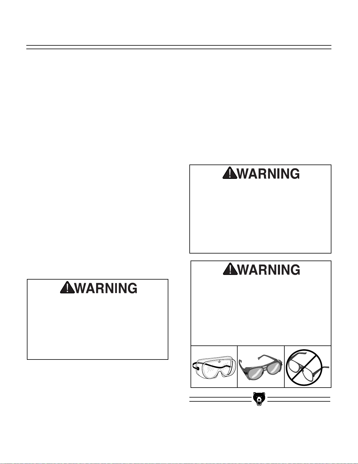
Operating this equipment has the potential
for flying debris to cause eye injury. Always
wear safety glasses or goggles when operating equipment. Everyday glasses or reading glasses only have impact resistant lenses, they are not safety glasses. Be certain
the safety glasses you wear meet the appropriate standards of the American National
Standards Institute (ANSI).
Page 33

Model G1019Z 14" Bandsaw -31-
Design Type ......................................................................................................Floor Model
Overall Dimensions:
Table......................................................................................13
7
⁄8" x 137⁄8" x 11⁄8" Thick
Overall Height ..........................................................................................................65"
Height From Floor to Table ..................................................................................42
1
⁄2"
Width of Unit ............................................................................................................26"
Depth of Unit ............................................................................................................22"
Shipping Weight ................................................................................................165 lbs.
Weight in Place ................................................................................................155 lbs
Box Size......................................................................................45" L x 22" W x 11" H
Foot Print......................................................................................................25
1
⁄2" x 19"
Cutting Capacity:
Left of Blade ..........................................................................................................14
1
⁄4"
Height ......................................................................................................................6
3
⁄8"
Table Tilt ..........................................................................................10° Left; 45° Right
Construction:
Table ..................................................................................Precision Ground Cast Iron
Wheels ............................................Fully Balanced Cast Aluminum with Rubber Tires
Rip Fence..........................................................Cast Iron Fence ⁄ Steel and Bar Stock
Wheel Covers....................................................................................Pre-Formed Steel
Guides ....................................................Steel Blocks with Rear Ball Bearing Support
Stand ................................................................................................Pre-Formed Steel
Motor:
Type ............................................................................TEFC Capacitor Start Induction
Horsepower ..........................................................................................................1 H.P.
Phase ⁄ Cycle ..............................................................................Single Phase ⁄ 60 Hz
Voltage ..............................................................................110V ⁄ 220V Prewired 110V
Amps ....................................................................................................................12 ⁄ 6
Power Transfer ..............................................................................................Belt Drive
R.P.M. ....................................................................................................................1720
Bearings ........................................................Shielded & Permanently Lubricated Ball
Switch......................................................................Toggle On/Off w/ Safety Lock Tab
Blades:
Sizes Available ......................................................................................From
1
⁄8" to 3⁄4"
Standard Blade Length ............................................................................................98"
Blade Speeds ................................................................................2500 & 3350 F.P.M.
Features:
................................................................Includes: Fence, Miter Gauge and
1
/2" Blade
....................................................................................................................2" Dust Port
Specifications, while deemed accurate, are not guaranteed.
Customer Service #: (570) 546-9663 • To Order Call: (800) 523-4777 • Fax #: (800) 438-5901
GRIZZLY MODEL G1019Z 14" BANDSAW
MACHINE DATA
SHEET
Page 34

-32- Model G1019Z 14" Bandsaw
SYMPTOM
Motor will not start.
Motor will not start; fuses
or circuit breakers blow.
Motor overheats.
Motor stalls (resulting in
blown fuses or tripped
circuit).
Machine slows when
operating.
Blade does not run evenly on wheels or runs off.
Blade does not cut evenly.
Ticking sound when the
saw is running.
Blade contacting table
insert.
Excessive vibration.
Burn marks on the edge
of the cut.
POSSIBLE CAUSE
1. Low voltage.
2. Open circuit in motor or loose
connections.
1. Short circuit in line cord or
plug.
2. Short circuit in motor or loose
connections.
3. Incorrect fuses or circuit
breakers in power line.
1. Motor overloaded.
2. Air circulation through the
motor restricted.
1. Short circuit in motor or loose
connections.
2. Low voltage.
3. Incorrect fuses or circuit
breakers in power line.
4. Motor overloaded.
1. Applying too much pressure
to workpiece.
2. Blade is dull.
1. Tracking is not adjusted
properly.
2. Rubber tire on wheel is damaged or worn.
3. Wheels are not coplanar.
1. Blade tension is incorrect.
2. Tooth set is uneven.
3. Teeth are sharper on one
side than the other.
1. Blade weld contacting support bearing.
2. Blade weld may be failing.
1. Excessive side pressure
when cutting.
2. Table improperly adjusted.
1. Wheels not coplanar.
2. Tires incorrectly installed.
3. Bent or worn out blade.
4. Wheels out of balance.
1. Too much side pressure
when feeding workpiece.
2. Blade too wide for size of
radius being cut.
CORRECTIVE ACTION
1. Check power line for proper voltage.
2. Inspect all lead connections on motor for loose or
open connections.
1. Inspect cord or plug for damaged insulation and
shorted wires.
2. Inspect all connections on motor for loose or shorted terminals or worn insulation.
3. Install correct fuses or circuit breakers.
1. Reduce load on motor.
2. Clean out motor to provide normal air circulation.
1. Inspect connections on motor for loose or shorted
terminals or worn insulation.
2 Correct the low voltage conditions.
3. Install correct fuses or circuit breakers.
4. Reduce load on motor.
1. Feed workpiece slower.
2. Replace blade.
1. Adjust tracking.
2. Replace rubber tires.
3. Adjust wheel coplanarity.
1. Adjust tension.
2. Replace blade, or have it professionally sharpened.
3. Replace blade, or have it professionally sharpened.
1. Use file or stone to smooth and round the back of
the blade.
2. Inspect and replace blade if necessary.
1. Reduce side pressure.
2. Adjust table.
1. Adjust wheels coplanar.
2. Re-install tires.
3. Replace blade.
4. Replace wheels.
1. Feed workpiece straight into the blade.
2. Install a smaller width blade, and/or increase blade
tension.
TROUBLESHOOTING
Page 35

Model G1019Z 14" Bandsaw -33-
Page 36

-34- Model G1019Z 14" Bandsaw
Page 37

Model G1019Z 14" Bandsaw -35-
Page 38

-36- Model G1019Z 14" Bandsaw
Page 39

Model G1019Z 14" Bandsaw -37-
60A PVM25 V-BELT M-25 3L250
61 P1019Z061 MOTOR PULLEY
62 P1019Z062 ECCENTRIC GUIDE POST
63 P1019Z063 UPPER SUPPORT BRACKET
64 PN05 NUT 1⁄4"-20
65 PB05 HEX BOLT
1
⁄4"-20 x 3⁄4"
66 P1019Z066 THUMB SCREW
1
⁄4"-20 x 3⁄4"
67 P1019Z067 UPPER SPACING SLEEVE
68 P6200 BALL BEARING 6200
69 P1019Z069 C-RING S10
70 P1019Z070 THUMB SCREW 1⁄4"-20 x 1⁄2"
71 P1019Z071 SUPPORT BRACKET
72 P1019Z072 GUIDE BLOCK
73 P1019Z073 UPPER BLADE GUIDE
74 PW06 FLAT WASHER 1⁄4"
75 PLW02 LOCK WASHER 1⁄4"
76 PB51 HEX BOLT 1⁄4"-20 x 3⁄8"
77 P1019Z077 TABLE INSERT
78 PRP15M ROLL PIN 3 x 8
79A P1019Z079A TABLE
80 P1019Z080 TABLE PIN
81 PB35 HEX BOLT 3⁄8"-16 x 21⁄2"
82 P1019Z082 TRUNNION CLAMP SHOE
83 P1019Z083 TRUNNION
84 PLW02 LOCK WASHER 1⁄4"
85 P1019Z085 HEX BOLT 1⁄4
"-20 x
5
⁄8
"
86 P1019Z086 SCALE
87 PB12 HEX BOLT
5
⁄16"-18 x 11⁄4"
88 PW07 FLAT WASHER 5⁄16"
89 P1019Z089 TABLE BRACKET
90 P1019Z090 POINTER
91 PS01 PHLP HD SCREW 10-24 x 1⁄2"
92 P1019Z092 LOCKING KNOB
93 PB60 HEX BOLT 3⁄8"-16 x 3"
94 P1019Z094 LWR SUPPORT BRKT POST
95 P1019Z095 SPACER
96 P1019Z096 FENCE RAIL
97 PSB07M CAP SCREW M6-1 x 30
98 P1019Z098 RAIL CAP
99 P1019Z099 FENCE ASSEMBLY
100 P1019Z100 LOCKING KNOB BOLT
101A P1019Z101A GAUGE BAR
102 P1019Z102 POINTER
103 P1019Z103 PANHEAD SCREW
105 P1019Z105 GAUGE
106 P1019Z106 LOCKING BOLT
107 P1019Z107 STAND TOP PLATE
108 P1019Z108 UPPER SIDE BRACE
109A P1019Z109A LOWER SIDE BRACE
110A P1019Z110A LOWER BRACE
111A P1019Z111A STAND LEG
112 PCB02 CARRIAGE BOLT 5⁄16"-18 x1⁄2"
113 PW07 FLAT WASHER 5⁄16"
114 PLW01 LOCK WASHER 5⁄16"
115 PN02 HEX NUT 5⁄16"-18
116 P1019Z116 HEX BOLT 3⁄8"-16 x 3"
118 PB03 HEX BOLT 5⁄16"-18 x 1"
130 P1019Z130 RUBBER FOOT
REF PART # DESCRIPTION
1 P1019Z001 BODY
2A P1019Z002A ARM
3 PB64 HEX BOLT
5
⁄8
"-11 x 2
1
⁄2
"
4 PW14 WASHER
5
⁄8"
5 PN06 HEX NUT 5⁄8"-11
6 P1019Z006 PIN 6 x 16
7 P1019Z007 CORD HOLDER 1⁄2"
8A
PWRCRDPLUG
POWER CORD W/PLUG
8B
PWRCRDRECP
POWER CORD W/RECP
9 PWRCRD110L POWER CORD 110V, LONG
10 P1019Z010 BEARING BASE
11 P6203 BALL BEARING 6203ZZ
12 P1019Z012 SHAFT
13 P1019Z013 KEY 5 x 5 x 30
14 PLW01 LOCK WASHER 5⁄16"
15 PSB03 CAP SCREW 5⁄16"-18 x 1
16 P1019Z016 KNOB BOLT 5⁄16" x 1"
17 PLW06 LOCK WASHER 5⁄8"
18 P1019Z018 PIN 5 x 25
19 P1019Z019 JAM NUT 3⁄4"-16 RH
20 P1019Z020 BEARING COVER
21 P1019Z021 MOTOR
22 PK34M KEY 5 x 5 x 20
23 PW02 WASHER 3⁄8"
24 PSB06 CAP SCREW 1⁄4"-20 x 7⁄8"
25 P1019Z025 BAR SETTING PLATE
26 P1019Z026 SPRING
27 P1019Z027 GUARD SLEEVE (L)
28 PB12 HEX BOLT 5⁄16
"-18 x 1
1
⁄4
"
29 PN08 HEX NUT
3
⁄8"-16
30 P1019Z030 GUARD SLEEVE (S)
31 PB16 HEX BOLT 3⁄8
"-16 x 1
1
⁄2
"
32 P1019Z032 SLIDING BRACKET
33 P1019Z033 BLADE ADJUSTING SCREW
34 P1019Z034 KNOB SCREW
35A P1019Z035A SWITCH PLATE (N/S)
36 P1019Z036 SPRING
37 P1019Z037 SQUARE NUT
3
⁄8"-16
38 P1019Z038 SHAFT HINGE W/ SHAFT
39 P1019Z039 PHLP HD SCREW 3⁄16"x 1⁄2"
40 P1019Z040 STEEL PIN
42 P1019Z042 INNER WHEEL COVER
43 PW06 WASHER 1⁄4"
44 PS01 PHLP HD SCREW 10-24 x 1⁄2"
45 P6202 BALL BEARING 6202
46 P1019Z046 RETAINING RING R35
47 P1019Z047 UPPER WHEEL
48 P1019Z048 WHEEL PROTECTOR
49 P1019Z049 HEX NUT 1⁄2" RH
50 P1019Z050 BLADE
51 P1019Z051 BLADE GUARD
52 PSW06 SWITCH 110/220V
53 P1019Z053 UPPER WHEEL COVER
54 P1019Z054 CATCH KNOB
55 P1019Z055 LOWER WHEEL COVER
56 PSS11 SETSCREW 1⁄4"-20 x 1⁄4"
57 P107383A JAM NUT 3⁄
4"-16 LH
58 P1019Z058 LOWER WHEEL
59A P1019Z059A BELT PULLEY (N/S)
REF PART # DESCRIPTION
PARTS LIST
Page 40

-38- Model G1019Z 14" Bandsaw
Grizzly Industrial, Inc. warrants every product it sells for a period of 1 year to the original purchaser from
the date of purchase. This warranty does not apply to defects due directly or indirectly to misuse, abuse,
negligence, accidents, repairs or alterations or lack of maintenance. This is Grizzly’s sole written warranty
and any and all warranties that may be implied by law, including any merchantability or fitness, for any particular purpose, are hereby limited to the duration of this written warranty. We do not warrant or represent
that the merchandise complies with the provisions of any law or acts unless the manufacturer so warrants.
In no event shall Grizzly’s liability under this warranty exceed the purchase price paid for the product and
any legal actions brought against Grizzly shall be tried in the State of Washington, County of Whatcom.
We shall in no event be liable for death, injuries to persons or property or for incidental, contingent, special, or consequential damages arising from the use of our products.
To take advantage of this warranty, contact us by mail or phone and give us all the details. We will then
issue you a “Return Number,’’ which must be clearly posted on the outside as well as the inside of the carton. We will not accept any item back without this number. Proof of purchase must accompany the merchandise.
The manufacturers reserve the right to change specifications at any time because they constantly strive to
achieve better quality equipment. We make every effort to ensure that our products meet high quality and
durability standards and we hope you never need to use this warranty.
Please feel free to write or call us if you have any questions about the machine or the manual.
Thank you again for your business and continued support. We hope to serve you again soon.
WARRANTY AND RETURNS
Page 41

CUT ALONG DOTTED LINE
10. Which benchtop tools do you own? Check all that apply.
___1" x 42" Belt Sander ___6" - 8" Grinder
___5" - 8" Drill Press ___Mini Lathe
___8" Table Saw ___10" - 12" Thickness Planer
___8" - 10" Bandsaw ___Scroll Saw
___Disc/Belt Sander ___Spindle/Belt Sander
___Mini Jointer
___Other__________________________________________________
11. How many of the machines checked above are Grizzly? ____________
12. Which portable/hand held power tools do you own? Check all that apply.
___Belt Sander ___Orbital Sander
___Biscuit Joiner ___Palm Sander
___Circular Saw ___Portable Planer
___Detail Sander ___Saber Saw
___Drill/Driver ___Reciprocating Saw
___Miter Saw ___Router
___Other__________________________________________________
13. What machines/supplies would you like Grizzly Industrial to carry?
___12" Table Saw ___Radial Arm Saw
___12" Jointer ___Panel Saw
___Combination Planer/Jointer ___Brass Hardware
___Paint & Finishing Supplies ___Lumber
___Contractor’s Supplies
___Other__________________________________________________
14. What new accessories would you like Grizzly Industrial to carry?
___Builders Hardware ___Hand Tools
___Fasteners ___Wood Components
___Other__________________________________________________
15. What other companies do you purchase your tools and supplies from?
__________________________________________________________
__________________________________________________________
16. Do you think your purchase represents good value?
___Yes ___No
17. Would you recommend Grizzly Industrial to a friend?
___Yes ___No
18. Would you allow us to use your name as a reference for Grizzly customers
in your area? Note: We never use names more than three times.
___Yes ___No
19. Comments:_________________________________________________
__________________________________________________________
__________________________________________________________
__________________________________________________________
__________________________________________________________
1. How did you learn about us?
___Advertisement ___Friend
___Catalog ___Card Deck
___World Wide Web
___Other__________________________________________________
2. Which of the following magazines do you subscribe to.
___American Woodworker ___Practical Homeowner
___Cabinetmaker ___Shop Notes
___Family Handyman ___Today’s Homeowner
___Fine Homebuilding ___WOOD
___Fine Woodworking ___Wooden Boat
___Home Handyman ___Woodshop News
___Journal of Light Construction ___Woodsmith
___Old House Journal ___Woodwork
___Popular Mechanics ___Woodworker
___Popular Science ___Woodworker’s Journal
___Popular Woodworking ___Workbench
___Other__________________________________________________
3. Which of the following woodworking/remodeling shows do you watch?
___Backyard America ___The New Yankee Workshop
___Home Time ___This Old House
___The American Woodworker ___Woodwright’s Shop
___Other__________________________________________________
4. What is your annual household income?
___$20,000-$29,999 ___$60,000-$69,999
___$30,000-$39,999 ___$70,000-$79,999
___$40,000-$49,999 ___$80,000-$89,999
___$50,000-$59,999 ___$90,000 +
5. What is your age group?
___20-29 ___50-59
___30-39 ___60-69
___40-49 ___70 +
6. How long have you been a woodworker?
___0 - 2 Years ___8 - 20 Years
___2 - 8 Years ___20+ Years
7. How would you rank your woodworking skills?
___Simple ___Advanced
___Intermediate ___Master Craftsman
8. What stationary woodworking tools do you own? Check all that apply.
___Air Compressor ___Panel Saw
___Band Saw ___Planer
___Drill Press ___Power Feeder
___Drum Sander ___Radial Arm Saw
___Dust Collector ___Shaper
___Horizontal Boring Machine ___Spindle Sander
___Jointer ___Table Saw
___Lathe ___Vacuum Veneer Press
___Mortiser ___Wide Belt Sander
___Other__________________________________________________
9. How many of your woodworking machines are Grizzly? _____________
Name ____________________________________________________________________________________
Street ____________________________________________________________________________________
City ______________________________________________________________State________Zip_________
Phone Number_______________________E-Mail_______________________FAX________________________
MODEL #___G1019Z 14" Bandsaw________Order #______________________________________________
The following information is given on a voluntary basis. It will be used for marketing purposes to help us develop better products and services. Of course, all information is strictly confidential.
WARRANTY CARD
Page 42

TAPE ALONG EDGES--PLEASE DO NOT STAPLE
FOLD ALONG DOTTED LINE
FOLD ALONG DOTTED LINE
GRIZZLY INDUSTRIAL, INC.
P.O. BOX 2069
BELLINGHAM, WA 98227-2069
Place
Stamp
Here
Name_______________________________
Street_______________________________
City______________State______Zip______
Send a Grizzly Catalog to a friend:
Page 43

Page 44

 Loading...