


COPYRIGHT © JANUARY, 2003 BY GRIZZLY INDUSTRIAL, INC.
WARNING: NO PORTION OF THIS MANUAL MAY BE REPRODUCED IN ANY SHAPE
OR FORM WITHOUT THE WRITTEN APPROVAL OF GRIZZLY INDUSTRIAL, INC.
PRINTED IN TAIWAN
ONLINE MANUAL DISCLAIMER
THE INFORMATION IN THIS MANUAL REPRESENTS THE CONFIGURATION OF THE MACHINE AS IT IS CURRENTLY BEING SHIPPED. THE MACHINE
CONFIGURATION CAN CHANGE AS PRODUCT IMPROVEMENTS ARE INCORPORATED. IF YOU OWN AN EARLIER VERSION OF THE MACHINE, THIS
MANUAL MAY NOT EXACTLY DEPICT YOUR MACHINE . CONTACT CUSTOMER SERVICE IF YOU HAVE ANY QUESTIONS ABOUT DIFFERENCES. PRE-
VIOUS VERSIONS ARE NOT AVAILABLE ONLINE.
8" JOINTERS
MODEL G0500/G1018/G1018HW
INSTRUCTION MANUAL
Model G0500 Shown

WARNING
Some dust created by power sanding, sawing, grinding, drilling, and other construction activities contains
chemicals known to the State of California to cause
cancer, birth defects or other reproductive harm.
Some examples of these chemicals are:
• Lead from lead-based paints.
• Crystalline silica from bricks, cement, and
other masonry products.
• Arsenic and chromium from chemically treated
lumber.
Your risk from these exposures varies, depending on
how often you do this type of work. To reduce your
exposure to these chemicals: work in a well ventilated
area, and work with approved safety equipment, such
as those dust masks that are specially designed to filter out microscopic particles.

TABLE OF CONTENTS
PAGE
1. SAFETY........................................................................................................................................3
Safety Instructions For Power Tools ..................................................................................3-4
Additional Safety Instructions For Jointers ............................................................................5
2. INTRODUCTION ..........................................................................................................................6
3. CIRCUIT REQUIREMENTS ........................................................................................................7
220V Operation ......................................................................................................................7
110V Operation ......................................................................................................................8
Grounding ..............................................................................................................................9
Extension Cords ....................................................................................................................9
4. IDENTIFICATION..................................................................................................................10-11
Common Terms and Definitions ..........................................................................................11
5. SETUP........................................................................................................................................12
Unpacking ............................................................................................................................12
G0500 Inventory ..................................................................................................................12
G1018 Inventory ..................................................................................................................13
G1018HW Inventory ............................................................................................................13
Hardware Recognition Chart ................................................................................................14
Clean Up ..............................................................................................................................15
Site Considerations ..............................................................................................................15
Beginning Assembly ............................................................................................................16
Switch Installation ..........................................................................................................16-17
Wiring Connection ................................................................................................................17
Jointer Stand ........................................................................................................................18
V-Belt ..............................................................................................................................18-19
Stand Cover ........................................................................................................................19
Fence to Jointer....................................................................................................................20
G0500/G1018HW Handwheel Installation............................................................................20
G1018 Table Lever Installation ............................................................................................21
Knife Setting Gauge ............................................................................................................21
Knife Inspection....................................................................................................................22
Table Alignment ..............................................................................................................22-23
G1018 Table Stops ..............................................................................................................24
Cutterhead Guard ................................................................................................................25
Fence Stops ....................................................................................................................26-27
Plug Installation ....................................................................................................................27
Test Run ..............................................................................................................................27
6. OPERATIONS ............................................................................................................................28
Stock Inspection & Requirements ..................................................................................28-29
Squaring Stock ....................................................................................................................29
Surface Planing ....................................................................................................................30
Edge Jointing........................................................................................................................31
Bevel Cutting ........................................................................................................................32
Rabbet Cutting ....................................................................................................................33

7. MAINTENANCE..........................................................................................................................34
General ................................................................................................................................34
Table ....................................................................................................................................34
Lubrication ............................................................................................................................34
V-Belt....................................................................................................................................34
Knife Condition ....................................................................................................................34
Maintenance Log..................................................................................................................35
8. SERVICE ADJUSTMENTS ........................................................................................................36
About Service ......................................................................................................................36
Setting Knives ................................................................................................................36-37
Adjusting Gibs ................................................................................................................37-38
Adjusting V-Belt ..............................................................................................................38-39
Replacing V-Belt ..................................................................................................................39
Service Log ..........................................................................................................................40
9. REFERENCE INFO ....................................................................................................................41
Troubleshooting Guide....................................................................................................42-43
G0500/G1018/G1018HW Wiring Diagram ..........................................................................44
G0500 Machine Data ..........................................................................................................45
G0500 Parts Breakdown and Parts List..........................................................................46-51
G1018 Machine Data ..........................................................................................................52
G1018 Parts Breakdown and Parts List..........................................................................53-58
G1018HW Machine Data ....................................................................................................59
G1018HW Parts Breakdown and Parts List....................................................................60-65
Warranty Information ......................................................................................................66-67

G0500/G1018/G1018HW 8" Jointers
-3-
Safety Instructions For Power Tools
SECTION 1: SAFETY
5. KEEP CHILDREN AND VISITORS
AWAY. All children and visitors should be
kept at a safe distance from work area.
6. MAKE WORKSHOP CHILD PROOF with
padlocks, master switches, or by removing
starter keys.
7. NEVER FORCE TOOL. It will do the job
better and safer at the rate for which it was
designed.
8. USE RIGHT TOOL. Do not force tool or
attachment to do a job for which it was not
designed.
1. KEEP GUARDS IN PLACE and in working
order.
2. REMOVE ADJUSTING KEYS AND
WRENCHES. Form habit of checking to
see that keys and adjusting wrenches are
removed from tool before turning on.
3. KEEP WORK AREA CLEAN. Cluttered
areas and benches invite accidents.
4. NEVER USE IN DANGEROUS ENVIRONMENT. Do not use power tools in
damp or wet locations, or where any flammable or noxious fumes may exist. Keep
work area well lighted.
For Your Own Safety Read Instruction
Manual Before Operating This Equipment
Indicates an imminently hazardous situation which, if not avoided,
WILL result in death or serious injury.
Indicates a potentially hazardous situation which, if not avoided,
COULD
result in death or serious injury.
Indicates a potentially hazardous situation which, if not avoided,
MAY
result in minor or moderate injury. It may also be used to alert
against unsafe practices.
This symbol is used to alert the user to useful information about
proper operation of the equipment.
The purpose of safety symbols is to attract your attention to possible hazardous conditions.
This manual uses a series of symbols and signal words which are intended to convey the level
of importance of the safety messages. The progression of symbols is described below.
Remember that safety messages by themselves do not eliminate danger and are not a substitute for proper accident prevention measures.
NOTICE

-4-
G0500/G1018/G1018HW 8" Jointers
9. USE PROPER EXTENSION CORD. Make
sure your extension cord is in good condition. Conductor size should be in accordance with the chart below. The amperage
rating should be listed on the motor or tool
nameplate. An undersized cord will cause
a drop in line voltage resulting in loss of
power and overheating. Your extension
cord must also contain a ground wire and
plug pin. Always repair or replace extension cords if they become damaged.
Minimum Gauge for Extension Cords
10. WEAR PROPER APPAREL. Do not wear
loose clothing, gloves, neckties, rings,
bracelets, or other jewelry which may get
caught in moving parts. Non-slip footwear
is recommended. Wear protective hair covering to contain long hair.
11. ALWAYS USE SAFETY GLASSES. Also
use face or dust mask if cutting operation is
dusty. Everyday eyeglasses only have impact
resistant lenses, they are NOT safety glasses.
12. SECURE WORK. Use clamps or a vise to hold
work when practical. It’s safer than using your
hand and frees both hands to operate tool.
13. DO NOT OVER-REACH. Keep proper
footing and balance at all times.
14. MAINTAIN TOOLS WITH CARE. Keep
tools sharp and clean for best and safest
performance. Follow instructions for lubricating and changing accessories.
LENGTH
AMP RATING 25ft 50ft 100ft
0-6 16 16 16
7-10 16 16 14
11-12 16 16 14
13-16 14 12 12
17-20 12 12 10
21-30 10 10 No
Safety Instructions For Power Tools
15. USE RECOMMENDED ACCESSORIES.
Consult the owner’s manual for recommended accessories. The use of improper
accessories may cause risk of injury.
16. REDUCE THE RISK OF UNINTENTIONAL STARTING. On machines with magnet-
ic contact starting switches there is a risk of
starting if the machine is bumped or jarred.
Always disconnect from power source
before adjusting or servicing. Make sure
switch is in OFF position before reconnecting.
17. CHECK DAMAGED PARTS. Before fur-
ther use of the tool, a guard or other part
that is damaged should be carefully
checked to determine that it will operate
properly and perform its intended function.
Check for alignment of moving parts, binding of moving parts, breakage of parts,
mounting, and any other conditions that
may affect its operation. A guard or other
part that is damaged should be properly
repaired or replaced.
18. NEVER LEAVE TOOL RUNNING UNATTENDED. TURN POWER OFF. Do not
leave tool until it comes to a complete stop.
19. NEVER OPERATE A MACHINE WHEN
TIRED, OR UNDER THE INFLUENCE OF
DRUGS OR ALCOHOL. Full mental alert-
ness is required at all times when running a
machine.
20. NEVER ALLOW UNSUPERVISED OR
UNTRAINED PERSONNEL TO OPERATE THE MACHINE. Make sure any
instructions you give in regards to machine
operation are approved, correct, safe, and
clearly understood.
21. IF AT ANY TIME YOU ARE EXPERIENCING DIFFICULTIES performing the intend-
ed operation, stop using the machine! Then
contact our service department or ask a
qualified expert how the operation should
be performed.
G0500/G1018/G1018HW 8" Jointers -5-
Like all power tools, there is danger associated with the Grizzly 8" Jointers.
Accidents are frequently caused by lack of
familiarity or failure to pay attention. Use
this tool with respect and caution to lessen
the possibility of operator injury. If normal
safety precautions are overlooked or
ignored, serious personal injury may
occur.
No list of safety guidelines can be complete.
Every shop environment is different. Always
consider safety first, as it applies to your
individual working conditions. Use this and
other machinery with caution and respect.
Failure to do so could result in serious personal injury, damage to equipment or poor
work results.
Additional Safety Instructions For Jointers
1. JOINTING SAFETY BEGINS with your
lumber. Inspect your stock carefully before
you feed it over the cutterhead. If you have
any doubts about the stability or structural
integrity of your stock, DO NOT JOINT IT!
2. MAINTAIN PROPER RELATIONSHIP of
the outfeed table and the cutterhead knife
path.
3. ALWAYS USE PUSH BLOCKS whenever
surface planing. Never place your hands
directly over the cutterhead.
4. SUPPORT THE WORKPIECE adequately
at all times during operation, maintain control over the work at all times.
5. WHEN JOINTING, do not stand directly at
the end of either table. Position yourself
just to the side of the infeed table to avoid
injury from possible kickbacks.
6. NEVER MAKE ANY SINGLE CUT DEEPER THAN
1
⁄8".
7. NEVER JOINT A BOARD that has loose
knots. All defects should be cut out of the
board before it is planed or jointed.
8. NEVER JOINT end grain.
9. JOINT WITH THE GRAIN. Jointing against
the grain is dangerous and could produce
chatter or excessive chip out.
10. WITH THE EXCEPTION OF RABBETING,
all operations must be performed with the
guard in place. After rabbeting, be sure to
replace the guard.
11. NEVER BACK THE WORK toward the
infeed table.
12. HABITS – GOOD AND BAD – are hard to
break. Develop good habits in your shop
and safety will become second-nature to
you.
13. “KICKBACK” is when the workpiece is
thrown off the jointer table by the force of
the cutterhead. Always use pushblocks and
safety glasses to reduce the likelihood of
injury from “kickback.” If you do not understand what kickback is, or how it occurs,
DO NOT operate this machine.
14. BE AWARE THAT CERTAIN WOODS
MAY CAUSE AN ALLERGIC REACTION
in people and animals, especially when
exposed to fine dust. Make sure you know
what type of wood dust you will be exposed
to and always wear an approved respirator.
-6-
G0500/G1018/G1018HW 8" Jointers
We are proud to offer the Model
G0500/G1018/G1018HW. These 8" jointers are
part of a growing Grizzly family of fine woodworking machinery. When used according to the
guidelines set forth in this manual, you can
expect years of trouble-free, enjoyable operation
and proof of Grizzly’s commitment to customer
satisfaction.
The main differences in the three models are
shown in the chart below. All three machines are
built with rugged steel cabinets and precision
ground cast-iron tables and fence assemblies.
For more complete information about each
machine, see Section 9: Reference Info.
We are pleased to provide this manual with the
Model G0500/G1018/G1018HW. It was written to
guide you through assembly, review safety considerations, and cover general operating procedures. It represents our effort to produce the best
documentation possible.
If you have any comments regarding this manu-
al, please write to us at the address below:
Grizzly Industrial, Inc.
C
/O Technical Documentation
P.O. Box 2069
Bellingham, WA 98227-2069
Most importantly, we stand behind our machines.
If you have any service questions or parts
requests, please call or write us at the location
listed below.
Grizzly Industrial, Inc.
1203 Lycoming Mall Circle
Muncy, PA 17756
Phone: (570) 546-9663
Fax: (800) 438-5901
E-Mail: techsupport@grizzly.com
Web Site: http://www.grizzly.com
The specifications, drawings, and photographs
illustrated in this manual represent the Model
G0500/G1018/G1018HW as supplied when the
manual was prepared. However, owing to
Grizzly’s policy of continuous improvement,
changes may be made at any time with no obligation on the part of Grizzly. For your convenience, we always keep current Grizzly manuals
available on our website at www.grizzly.com
. Any
updates to your machine will be reflected in these
manuals as soon as they are complete. Visit our
site often to check for the latest updates to this
manual!
SECTION 2: INTRODUCTION
Read the manual before
assembly and operation.
Serious personal injury
may result if safety or
operational information
is not understood or followed.
Description
Motor
Cutterhead
Table Size
Table
Adjustment
G0500
2 HP
4 Knife
75"
Handwheels
G1018
1
1
⁄2 HP
3 Knife
65"
Table Levers
G1018HW
1
1
⁄2 HP
3 Knife
65"
Handwheels

G0500/G1018/G1018HW 8" Jointers -7-
220V Operation
SECTION 3: CIRCUIT REQUIREMENTS
Amperage Draw
The Model G0500/G1018/G1018HW motors are
prewired at 220V and will draw the following load:
G0500....................................................12 amps
G1018......................................................9 amps
G1018HW................................................9 amps
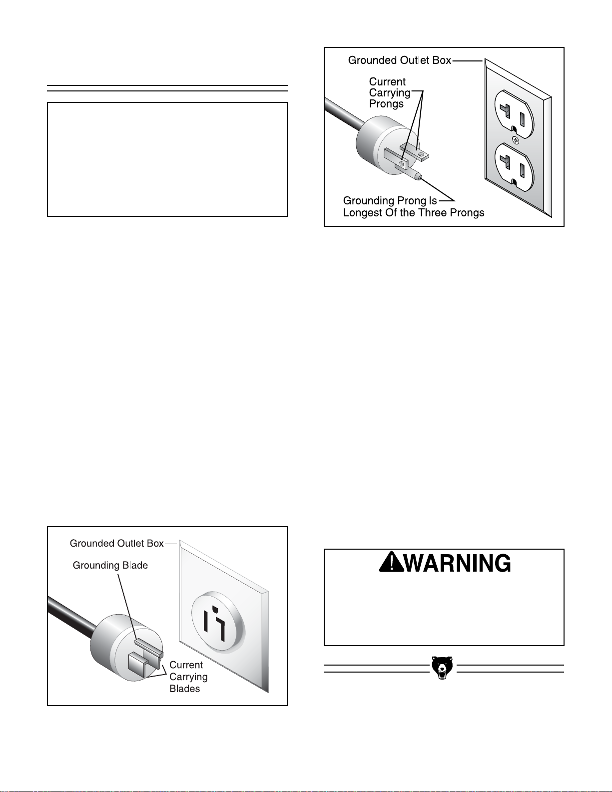
Plug Type
The cord set enclosed does not have a plug as
the style of plug you require will depend upon the
type of service you currently have or plan to
install. We recommend using the following plugs
for your machine on a dedicated circuit only (see
Figure 1 for an example):
G0500............................................6-15 or L6-15
G1018............................................6-15 or L6-15
G1018HW......................................6-15 or L6-15
Circuit Breaker Requirements
We recommend that the circuit you use your
machine on should be dedicated. Because the
machine motors are different sizes, please use
the following guidelines when choosing a circuit
breaker for your machine (circuit breakers rated
any higher are not adequate to protect the circuit):
G0500 ....................................................15 amp
G1018 ....................................................10 amp
G1018HW ..............................................10 amp
Your Circuit Capacity
Always check to see if the wires in your circuit are
capable of handling the amperage load from your
machine. If you are unsure, consult a qualified
electrician.
If you operate your jointer on any circuit that is
already close to its capacity, it might blow a fuse
or trip a circuit breaker. However, if an unusual
load does not exist and a power failure still
occurs, contact a qualified electrician or our
Service Department.
Figure 1. 6-15 plug and outlet.
DO NOT connect your machine to the power
source until you have completed the assembly process and have been instructed to do
so in this manual. Otherwise, serious personal injury could occur.
-8-
G0500/G1018/G1018HW 8" Jointers
110V Operation
110V Amperage Draw
The Model G0500/G1018/G1018HW motors can
be rewired for 110V if you use a different switch.
If you rewire your machine for 110V, the motors
will draw the following load:
G0500......................................................24 amp
G1018......................................................18 amp
G1018HW................................................18 amp
Plug Type
The cord set enclosed does not have a plug as
the style of plug you require will depend upon the
type of service you currently have or plan to
install. We recommend using the following plugs
for your machine on a dedicated circuit only (see
Figures 2 & 3 for examples):
G0500............................................5-30 or L5-30
G1018............................................5-20 or L5-20
G1018HW......................................5-20 or L5-20
NOTICE
The Model G0500/G1018/G1018HW is
prewired for 220V operation. If you plan to
rewire your machine for 110V, you must
use a different switch. Consult a licensed
electrician before attempting to rewire your
machine!
Figure 3. 5-20 plug and outlet.
Figure 2. 5-30 plug and outlet.
DO NOT connect your machine to the power
source until you have completed the assembly process and have been instructed to do
so in this manual. Otherwise, serious personal injury could occur.
110V Circuit Breaker Requirements
Use the following guidelines when choosing a circuit breaker (circuit breakers rated any higher are
not adequate to protect the circuit):
G0500......................................................25 amp
G1018......................................................20 amp
G1018HW................................................20 amp
Your Circuit Capacity
Always check to see if the wires in your circuit are
capable of handling the amperage load from your
machine. If you are unsure, consult a qualified
electrician.
If you operate your jointer on any circuit that is
already close to its capacity, it might blow a fuse
or trip a circuit breaker. However, if an unusual
load does not exist and a power failure still
occurs, contact a qualified electrician or our
Service Department.

G0500/G1018/G1018HW 8" Jointers -9-
Grounding
In the event of an electrical short, grounding
reduces the risk of electric shock by providing a
path of least resistance to disperse electric current. This tool is equipped with a power cord that
has an equipment-grounding prong. The outlet
must be properly installed and grounded in accordance with all local codes and ordinances.
This machine must have a ground prong in
the plug to help ensure that it is grounded.
DO NOT remove ground prong from plug to
fit into a two-pronged outlet! If the plug will
not fit the outlet, have the proper outlet
installed by a qualified electrician.
Verify that any existing
electrical outlet and circuit you use is actually
grounded. If not, it will be
necessary to run a separate 12 A.W.G. copper
grounding wire from the
outlet to a known ground.
If not grounded properly,
serious personal injury
could occur.
220V Operation
We do not recommend the use of extension cords
on 220V equipment. Instead, arrange the placement of your equipment and the installed wiring to
eliminate the need for extension cords.
If you find it absolutely necessary to use an
extension cord at 220V with your Grizzly 8"
Jointer:
•Make sure the cord is rated for Standard
Service (grade S) or better.
• The extension cord must also contain a
ground wire and plug pin.
• Use at least a 16 gauge cord if the cord is 50
feet long or less.
• Use at least a 14 gauge cord if the cord is
between 51-100 feet.
110V Operation
If you find it necessary to use an extension cord
at 110V with your Grizzly 8" jointer:
• Make sure the cord is rated Standard Service
(grade S) or better.
• The extension cord must also contain a
ground wire and plug pin.
• Use at least a 10 gauge cord if the cord is 50
feet long or less.
•DONOT use a cord longer that 50 feet!
Extension Cords
-10-
G0500/G1018/G1018HW 8" Jointers
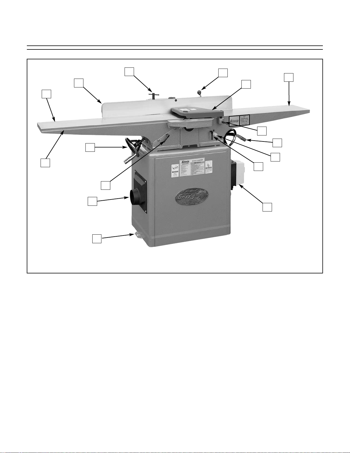
Figure 4. The following is a list of controls and components on the Model G0500/G1018/G1018HW. Please
take time to become familiar with each item and its location. These items will be used throughout the manual and knowing them is essential to understanding the instructions and terminology used in this manual.
1. Fence Lock
2. Fence
3. Outfeed Table
4. Rabbeting Edge
5. Outfeed Handwheel
6. Outfeed Table Lock
7. Dust Port (optional for G1018/G1018HW)
8. Stand Mounting Hole
9. ON/OFF Switch
10. Infeed Table Lock
11. Depth Scale
12. Infeed Table Handwheel
13. Cutterhead Guard Shaft Lock
14. Infeed Table
15. Cutterhead Guard
16. Fence Tilt Handle
SECTION 4: IDENTIFICATION
2
1
3
5
4
7
6
9
12
11
13
15
14
16
10
8
G0500/G1018/G1018HW 8" Jointers -11-
Common Terms and Definitions
Infeed Table: The infeed table is the table where
the cutting operation begins. When facing the
front of the jointer, it is on the right-hand side.
The wood travels right to left; from the infeed
table, across the cutterhead, and onto the outfeed table.
Outfeed Table: The outfeed table is the table
where the cutting operation ends. When facing
the front of the jointer, it is on the left-hand
side.
Cutterhead: The cutterhead is the cylindrical
assembly that holds each of the jointer knives.
It spins on a horizontal axis between the infeed
and outfeed table, and is covered by the cutterhead guard.
Fence: The jointer fence is the adjustable cast
iron surface that the wood stock runs along
when jointing and surface planing. The fence is
adjustable from 45°-90° to the infeed and outfeed tables.
Adjustment Levers and Handwheels: Controls
the height of the infeed and outfeed tables.
Table Lock Handles: The threaded handles that
must be loosened before the height of the
tables can be adjusted. They are then tightened after the height is properly set.
Rabbet Cut: A rabbet cut is a groove cut along
the long edge of the wood stock, usually used
for making simple joints. The cutterhead guard
must be removed for this operation, so great
care is needed for safe operation.
Surface Planing: Surface planing is running the
face of the wood stock over the jointer. This
provides one flat side that is ready to be run
through a dedicated planing machine.
Edge Jointing: Edge jointing is running the long
edge of the wood stock over the jointer. This
provides one flat edge that is ready to be run
against the table saw rip fence or edge glued.
Cutterhead Guard: The metal guard that covers
the cutterhead and automatically moves out of
the way during operation, then automatically
moves back into place after the operation.
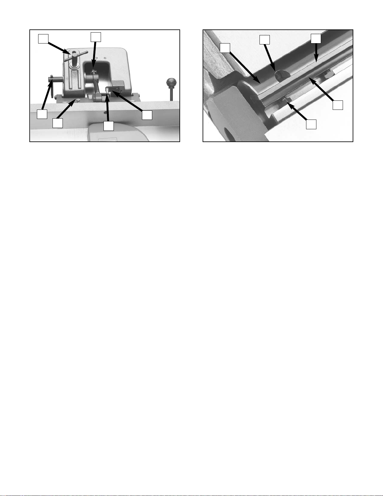
17. 45˚L Stop Nut
18. Fence Lock
19. Fence Tilt Lock
20. 45˚R Stop Bolt
21. 90˚ Stop Bolt
22. 90˚ Stop Tab
23. Cutterhead
24. Cutterhead Knife
25. Gib Bolt
26. Gib
27. Jack Screw Access Hole
17
18
21
19
22
26
25
27
24
23
20
Figure 5. Fence controls. Figure 6. Cutterhead details.
-12-
G0500/G1018/G1018HW 8" Jointers
Unpacking
The Grizzly 8" Jointers are shipped from the manufacturer in a carefully packed crate and a cardboard box. If you discover the machine is damaged after you’ve signed for delivery, and the
truck and driver are gone, you will need to file a
freight claim with the carrier. Save the containers
and all packing materials for possible inspection
by the carrier or its agent. Without the packing
materials, filing a freight claim can be difficult. If
you need assistance determining whether you
need to file a freight claim, or with the procedure
to file one, please contact our Customer Service.
When you are completely satisfied with the condition of your shipment, you should inventory its
parts.
G0500 Inventory
Some metal parts may
have sharp edges on
them after they are
formed. Please examine
the edges of all metal
parts before handling
them. Failure to do so
could result in injury.
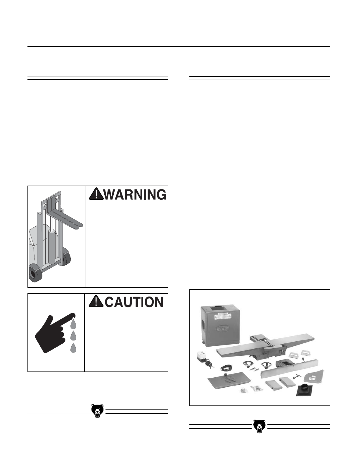
• Jointer Assembly w/Fence ........................1
• Infeed Extension ........................................1
• Outfeed Extension......................................1
• V-Belt M52..................................................2
• Handwheel..................................................2
• Handle ........................................................2
• Dust Port 4" ................................................1
• Hardware Bag #1
—Combo Wrench 8/10MM ........................1
—Combo Wrench 12/14MM ......................1
—Allen Wrench 3MM ................................1
—Allen Wrench 4MM ................................1
—Allen Wrench 5MM ................................1
—Phillips Head Screw 1⁄4"-20 X 1⁄2" ............4
—Flat Washer 1⁄4" ......................................4
—E-Clip ......................................................4
—Jig Feet ..................................................2
—Jig Rod....................................................1
• Hardware Bag #2
—Lock Washers 3⁄8"....................................3
—Hex Bolt 5⁄16"-18 x 1" ..............................4
—Flat Washer 5⁄16" ......................................4
—Special Mounting Bolts ..........................3
• Cutterhead Guard ......................................1
• Push Block..................................................2
• Stand Assembly w/Motor............................1
• Stand Door Assembly w/Knob....................1
• Strain Relief................................................1
• Phillips Head Screw #10-24 x 11⁄4" ............2
• Flat Washers #10 ......................................2
• Hex Nuts #10-24 ........................................2
The 8" Jointer is a heavy
machine at approximately 460 lbs. shipping
weight. DO NOT move
the machine by yourself
– you will need assistance and power equipment. Serious personal
injury may occur if safe
moving methods are not
followed.
SECTION 5: SET UP
Figure 7. G0500 Inventory.
G0500/G1018/G1018HW 8" Jointers -13-
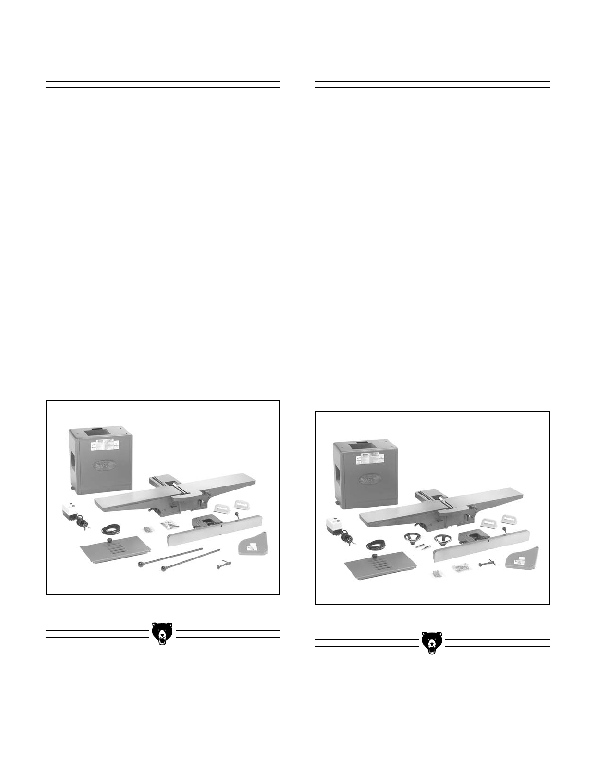
G1018 Inventory
• Jointer Assembly w/Fence ........................1
• V-Belt M52..................................................2
• Table Lever ................................................2
• Hardware Bag #1
—Combo Wrench 8/10MM ........................1
—Combo Wrench 12/14MM ......................1
—Allen Wrench 3MM ................................1
—Allen Wrench 4MM ................................1
—Allen Wrench 5MM ................................1
—E-Clip ......................................................4
—Jig Feet ..................................................2
—Jig Rod....................................................1
• Hardware Bag #2
—Lock Washers
3
⁄8"....................................3
—Special Mounting Bolts ..........................3
•Cutterhead Guard ......................................1
• Push Block..................................................2
• Stand Assembly w/Motor............................1
• Stand Door Assembly w/Knob....................1
• Strain Relief................................................2
• Phillips Head Screw #10-24 x 1
1
⁄4" ............2
• Flat Washers #10 ......................................2
• Hex Nuts #10-24 ........................................2
G1018HW Inventory
• Jointer Assembly w/Fence ........................1
• V-Belt M52..................................................2
• Handwheel..................................................2
• Handle ........................................................2
• Hardware Bag #1
—Combo Wrench 8/10MM ........................1
—Combo Wrench 12/14MM ......................1
—Allen Wrench 3MM ................................1
—Allen Wrench 4MM ................................1
—Allen Wrench 5MM ................................1
—E-Clip ......................................................4
—Jig Feet ..................................................2
—Jig Rod....................................................1
• Hardware Bag #2
—Lock Washers
3
⁄8"....................................3
—Special Mounting Bolts ..........................3
• Cutterhead Guard ......................................1
• Push Block..................................................2
• Stand Assembly w/Motor............................1
• Stand Door Assembly w/Knob....................1
• Strain Relief................................................2
• Phillips Head Screw #10-24 x 1
1
⁄4" ............2
• Flat Washers #10 ......................................2
• Hex Nuts #10-24 ........................................2
Figure 9. G1018HW Inventory.
Figure 8. G1018 Inventory.
-14- G0500/G1018/G1018HW 8" Jointers
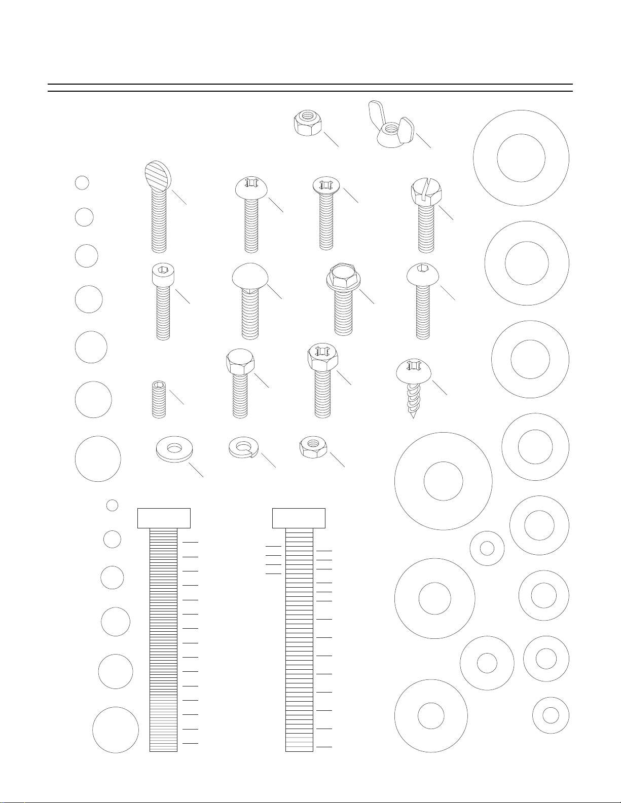
Hardware Recognition Chart
Use this chart to match up hardware
pieces during the assembly process!
Lock
Nut
#
10
1
⁄4''
Thumb
Screw
Phillips
Head
5
⁄16''
3
⁄8''
7
Cap
Screw
⁄16''
Screw
Carriage
Bolt
Hex
1
⁄2''
Setscrew
5
⁄8''
Head
Bolt
Lock
Washer
MEASURE BOLT DIAMETER BY PLACING INSIDE CIRCLE
4mm
6mm
5mm
10mm
8mm
15mm
20mm
Washer
1
⁄4''
3
⁄8''
1
⁄2''
5
⁄8''
25mm
10mm
30mm
35mm
40mm
45mm
12mm
LINES ARE 1MM APART
50mm
55mm
60mm
⁄16'' INCH APART
1
65mm
16mm
70mm
75mm
LINES ARE
Countersunk
Phillips
Head
Screw
Flange
Bolt
Phillips
Head
Hex
Bolt
Hex
Nut
5
⁄16''
7
⁄16''
9
⁄16''
3
⁄4''
7
⁄8''
1''
11⁄4''
1
⁄2''
1
3
⁄4''
1
2
1
⁄4''
2
1
⁄2''
2
3
⁄4''
2
3
Wing
Nut
Slotted
Screw
Button
Head
Screw
Phillips
Head
Sheet
Metal
Screw
D
I
A
R
12mm
D
I
A
D
I
A
M
M
E
T
E
R
D
R
E
H
S
A
W
M
4mm
E
T
E
R
D
R
E
H
S
A
W
6mm
E
T
E
R
A
S
S
H
A
H
W
E
W
S
A
E
E
H
W
R
10mm
R
8mm
WASHERS ARE MEASURED BY THE INSIDE DIAMETER
D
I
A
R
H
W
M
E
T
9
R
E
W
⁄8''
H
S
D
⁄16''
1
⁄2''
R
7
E
A
W
D
R
E
H
S
I
A
I
D
⁄16''
3
⁄8''
R
5
A
R
E
H
S
A
M
A
I
A
D
D
⁄16''
W
1
⁄4''
W
E
H
S
A
#
E
R
E
M
M
I
A
I
D
R
W
10
T
E
R
E
T
E
R
E
T
E
R
M
E
T
E
R
A
M
E
T
E
R
I
A
M
E
T
E
R
D
I
A
M
E
T
E
R
5
R
E
E
H
S
A
E
H
S
A
W
H
S
A
W
S
A
I
A
M
E
T
E
R
I
A
M
E
T
E
R
G0500/G1018/G1018HW 8" Jointers -15-
Site Considerations
Make your shop “child
safe.” Ensure that your
workplace is inaccessible
to youngsters by closing
and locking all entrances
when you are away. Never
allow visitors in your shop
when assembling, adjusting or operating equipment.
FLOOR AND WORKBENCH LOAD
Your Model G0500/G1018/G1018HW represents
a medium weight load. Most commercial or
garage shop floors should be sufficient to carry
the weight. Before moving the jointer onto a res-
idential floor, inspect it carefully to determine that
it will be sufficient to carry the load of the
machine, the device for moving it and its operators. If you question the strength of your floor, you
should consider having it inspected for possible
reinforcement.
WORKING CLEARANCES
Working clearances can be thought of as the distances between machines and obstacles that
allow safe operation of every machine without
limitation. Consider existing and anticipated
machine needs, size of material to be processed
through each machine, and space for auxiliary
stands and/or work tables. Also consider the relative position of each machine to one another for
efficient material handling.
LIGHTING AND OUTLETS
Lighting should be bright enough to eliminate
shadow and prevent eye strain. Electrical circuits
should be dedicated or large enough to handle
amperage requirements. Outlets should be located near each machine so power or extension
cords are clear of high-traffic areas. Observe
local electrical codes for proper installation of
new lighting, outlets, or circuits.
Clean Up
The unpainted surfaces are coated with a waxy
oil to protect them from corrosion during shipment. Remove this protective coating with a solvent cleaner or citrus-based degreaser such as
Grizzly’s G7895 Degreaser. To clean thoroughly,
some parts may need to be removed. For opti-
mum performance from your machine, make
sure you clean all moving parts or sliding
contact surfaces that are coated. Avoid chlo-
rine-based solvents as they may damage painted
surfaces should they come in contact.
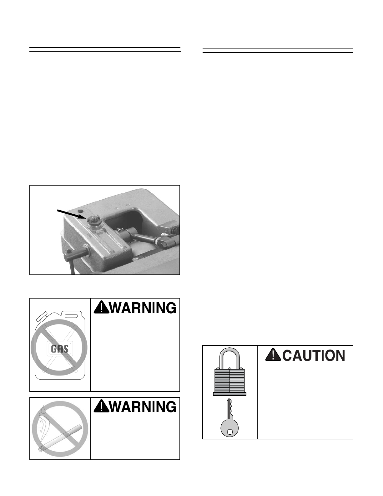
To access all surfaces, remove the fence lock nut
and handle (see Figure 10), and remove the
fence from the jointer unit.
Do not use gasoline or
other petroleum-based
solvents to clean with.
They have low flash
points which make them
extremely flammable. A
risk of explosion and
burning exists if these
products are used.
Do not smoke while using
solvents. A risk of explosion or fire exists and may
result in serious personal
injury.
Figure 10. Jointer fence lock nut (the handle is
attached directly underneath nut).
-16-
G0500/G1018/G1018HW 8" Jointers
4. Place the cover back on the switch and
secure it to the switch body with the two plastic screws.
5. Locate the shortest length cord (motor cord)
and close a grommet around the wire, so the
larger end of the grommet is toward the
switch.
6. Thread the motor cord through the access
hole in the stand, which is located just below
the switch.
This section will cover the minimum assembly
and adjustment instructions needed to begin
operation. For best results, complete the assembly in the order provided in this manual and then
read the remaining portion of the manual before
attempting any type of operations.
Safety must come first! Read and follow these
instructions before beginning assembly:
Switch Installation
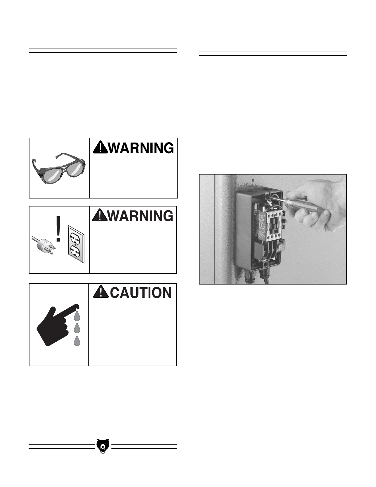
To install the switch:
1. Locate the #10-24 x 1
1
⁄2" Phillips head
screws that are included in the hardware bag
with the switch.
2. Remove the switch cover by unthreading the
two plastic screws from the front of the
switch.
3. Position the switch over the holes and secure
it to the stand with the #10-24 x 1
1
⁄2" Phillips
head screws, as shown Figure 11.
Figure 11. Fastening switch to stand.
Beginning Assembly
Most of your 8'' Jointer has been assembled at
the factory, but some parts must be assembled or
installed after delivery.
TOOLS REQUIRED: You will need a high quality
square, a Phillips screwdriver, a long straightedge, 10mm, 12mm and 14mm open-end
wrenches, and a 3mm Allen wrench.
Some metal parts may
have sharp edges on
them after they are
formed. Please examine
the edges of all metal
parts before handling
them. Failure to do so
could result in injury.
Disconnect power to the
machine when performing all assembly steps.
Failure to do this may
result in serious personal injury.
Wear safety glasses during the entire assembly
process. Failure to comply may result in serious
personal injury.
G0500/G1018/G1018HW 8" Jointers -17-
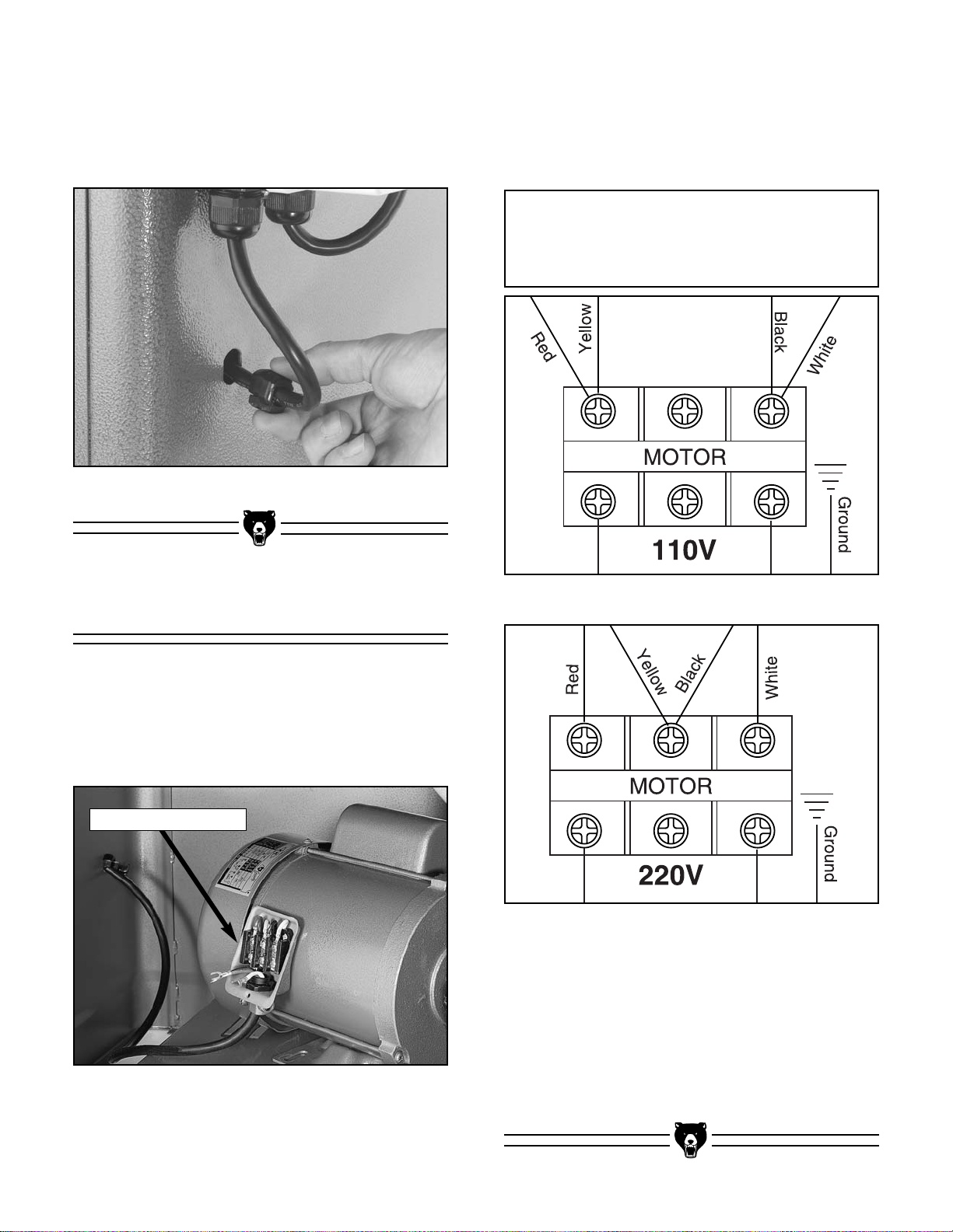
Wiring Connection
To connect the motor cord to the motor:
1. Remove three of the four motor mounting
bolts and swing the motor toward the rear
stand opening, as shown in Figure 13.
Figure 13. Motor positioned for easy access.
3. Make the motor connections in accordance
with the wiring schematics that are located
on the motor label or those shown below in
Figure 14 or Figure 15, depending on which
voltage you decide to use.
Figure 12. Installing grommet.
7. Snap fit the grommet into the opening as
shown in Figure 12. Make sure there is
enough slack in the wire between the switch
and the grommet before snapping the grommet into position.
Wiring Junction Box
Figure 14. 110V motor wiring schematic.
Figure 15. 220V motor wiring schematic.
2. Remove the cover from the wiring junction
box.
4. Make sure the wiring connections are
secure, then replace the wiring junction box
cover.
5. Swing the motor back into position and
replace the motor mounting bolts, but leave
them finger tight for now.
NOTICE
If you plan to rewire your machine for 110V,
you must use a different switch!
-18-
G0500/G1018/G1018HW 8" Jointers
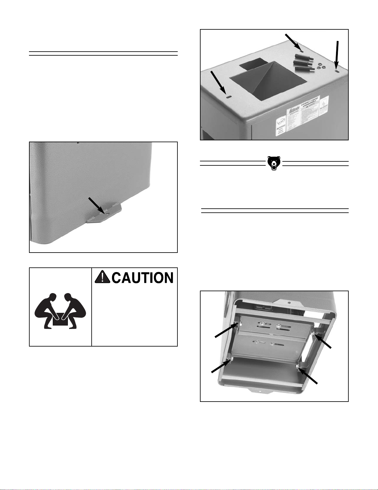
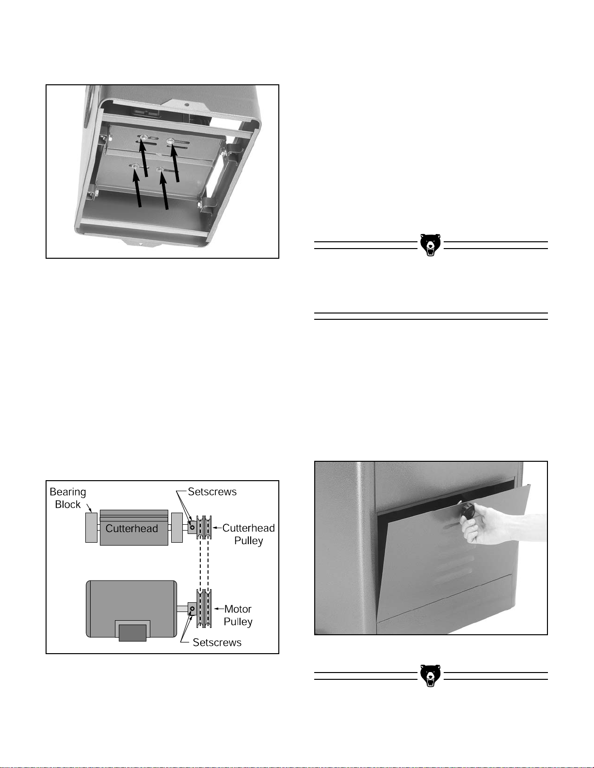
To mount the jointer to the stand:
1. Lift the main unit onto the stand and position
the cutterhead pulley over the pulley slot in
the top of the stand.
2. Carefully align the mounting holes in the
stand (shown in Figure 17) with the threaded
holes in the base of the jointer.
3. Secure the jointer to the stand using the (3)
3
⁄8"-16 x 3⁄4" hex bolts and 3⁄8" flat washers pro-
vided. Be sure not to over-tighten!
Jointer to Stand
The jointer unit is very
heavy—get assistance
when lifting it onto the
stand. Serious personal
injury may occur if safe
moving methods are not
followed.
Figure 18. Motor adjustment bolts (shown
underneath stand for clarity).
To install the V-belt:
1. Open the stand cover to access the motor
adjustment bolts.
2. Loosen the motor adjustment bolts shown in
Figure 18, and slide the motor up until you
can attach the V-belts to the pulleys.
V-Belt
Figure 16.
Jointer stand floor mounting flanges.
If you will be placing the jointer on a mobile base,
set the stand on the mobile base before installing
the jointer unit onto the stand.
If you will be bolting the stand to the floor, position the stand in its proper location and secure it
to the floor, using fasteners through the mounting
flanges shown in Figure 16, before installing the
jointer unit on the stand.
Figure 17.
Jointer unit mounting holes.
3. Allow the weight of the motor to rest against
the V-belts.
G0500/G1018/G1018HW 8" Jointers -19-
5. Move the motor on the mounting plate to
align the motor and cutterhead pulleys with
each other (See Figure 20). Visually confirm
the pulley alignment from above (for the best
accuracy use a straightedge for alignment
confirmation).
6. Tighten the motor mount bolts.
7. If necessary, the pulley alignment can be
fine tuned by loosening the motor pulley
setscrews and moving the pulley in or out as
necessary.
To install the stand cover:
1. Place the inset edge of the stand cover
against the bottom edge of the stand opening.
2. Close the stand cover against the stand as
shown in Figure 21, and turn the knob to
secure the stand cover to the stand.
Stand Cover
Figure 21. Closing stand cover.
Figure 20. Pulley and V-belt alignment.
8. Place firm tension on the motor and tighten
the motor adjustment bolts. Note—Only use
your hands to place tension on the motor.
DO NOT use a pry bar or any other device to
place added leverage on the motor.
9. Check the V-belts for proper tension by light-
ly squeezing both sides together. If the belts
can be easily squeezed together more than
1
⁄2" on each side, increase the tension. If the
pulley seems tight enough, continue with the
assembly process. (You can always go back
and make adjustments after the initial operation of the jointer.
Figure 19. Motor mount bolts (shown under-
neath stand for clarity).
4. Loosen the motor mount bolts shown in
Figure 19.
-20- G0500/G1018/G1018HW 8" Jointers
To install the fence on the jointer unit:
1. Place the fence on the jointer unit as it was
before you removed it for clean up. Make
sure the key on the fence support lines up
with the keyway on the fence.
2. Install the fence lock the opposite way that
you removed it before clean up, with the handle on top and the tabs of the nut facing up
as shown in Figure 22.
Fence to Jointer
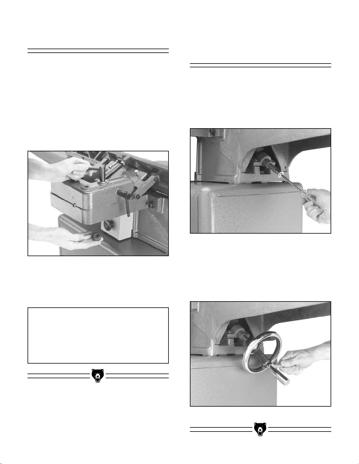
To install the handwheels on the Model
G0500/G1018HW:
1. Remove the screw and washer from the end
of the leadscrew under each table, as shown
in Figure 23.
G0500/G1018HW
Handwheel Installation
Figure 22. Installing fence lock with the tabs on
the nut facing up.
Figure 23. Removing screw from leadscrew.
Figure 24. Installing handle into handwheel.
3. Lock the fence in place by tightening the
fence lock.
NOTICE
The fence can easily scratch the table while
you are adjusting the fence position. To
avoid scratches, loosen the fence lock
enough to permit an easy adjustment and
always use care when moving the fence.
2. On each leadscrew, install a handwheel, and
secure it with the phillips head screw and
washer that you removed in step 1.
3. Install a handle into each handwheel, as
shown in Figure 24.

G0500/G1018/G1018HW 8" Jointers -21-
To assemble the knife setting gauge:
1. Insert the steel rod through the hole in each
adjuster arm until the notches for the E-clips
extend past the adjustment arms on both
sides.
2. Attach the E-clips to the notches to lock
adjustment arms onto the steel rod. The
adjustment arms are symmetrical, so the
placement is not a concern. See Figure 26.
Figure 26. Assembled knife setting gauge.
Knife Setting Gauge
To install the table levers on the Model
G1018HW:
1. Thread a table lever into the adjustment
block below each table, as shown in Figure
25.
G1018 Table
Lever Installation
Figure 25. Installing table lever into adjustment
block.
E-Clip

-22-
G0500/G1018/G1018HW 8" Jointers
Figure 29. Jointer.
Both tables can be adjusted by unlocking the
table locks (see Figure 29) and rotating the hand-
wheels. To accurately joint or plane a piece of
stock, both tables must be aligned correctly,
beginning with the outfeed table.
Table Alignment
The knives were set to their proper height at the
factory, but we recommend that you inspect them
to ensure proper operation and table setup.
To inspect the knife height:
1. Make sure that the power has not been con-
nected to the machine at this point in the
setup process!
2. Remove the belt guard shown in Figure 27.
Knife Inspection
Figure 27. Removing belt guard.
Figure 28. Jig placement on cutterhead.
3. Using the cutterhead pulley, rotate the cut-
terhead to make one of the knives accessible
to the knife jig. Lower the tables if it is necessary to make more room.
4. Place the jig over the knife as illustrated in
Figure 28.
5. Make sure that the middle pad of the jig is
barely touching the knife and that the pads
on the ends of the jig are resting firmly on the
cutterhead.
6. Repeat step 5 on all knives. If you find that
any knives are out of adjustment, correct
them as discussed in Section 7: Service
Adjustments.
To align the outfeed table:
1. Remove the belt guard so you can rotate the
cutterhead safely.
2. Rotate the cutterhead so that one of the
knives is at top dead center. Note—A knife is
at top dead center when it is at its highest
point during the rotation. See Figure 30 for
an illustration of a knife at top dead center.

G0500/G1018/G1018HW 8" Jointers -23-
Figure 30. Cutterhead knife at top-dead-center.
Figure 31. Outfeed table check.
Figure 32. Infeed table even with outfeed table.
Figure 33. Pointer set to 0.
3. Place a straightedge across the outfeed
table, so the end of the straightedge is directly over the knife.
4. If the outfeed table is set correctly, the
straightedge will lay across the table and
barely touch the knife when it is at top dead
center (see illustration in Figure 31). Verify
that the outfeed table height reflects this condition.
5. If the outfeed table needs to be adjusted,
release the outfeed table lock and adjust the
height by rotating the handwheel that is
located below the table.
6. When you have the outfeed table properly
adjusted, lock the table height in place.
To adjust the infeed table:
1. Make sure the outfeed table is adjusted as
previously described.
2. Place a straightedge half way on the outfeed
table and halfway over the infeed table.
3. Release the infeed table lock and adjust the
infeed table flush with the outfeed table as
illustrated in Figure 32. The infeed table
should be exactly the same height as the
outfeed table.
4. Lock the infeed table in place.
5. Set the pointer shown in Figure 33 to 0 on
the depth indicator scale.

-24-
G0500/G1018/G1018HW 8" Jointers
The Model G1018 has table stop bolts (see
Figure 34) that can be set to repeatedly bring the
table back to 0 on the depth indicator scale.
These table stop bolts are located directly under
both table adjustment levers. If you do not have
the Model G1018, skip these instructions.
G1018 Table Stops
Figure 34. Model G1018 table stop bolt (only
one side shown).
To set the Model G1018 outfeed table stop
bolt:
1. Make sure the outfeed table has been adjust-
ed as previously described.
2. Loosen the jam nut on the stop bolt, shown
in Figure 34.
3. Turn the stop bolt clockwise until it makes
contact with the table base behind the adjustment block.
4. Loosen the table lock and move the table
down, then move it up until it stops. Make
certain the table returns to its correct height
by verifying that the outfeed table is even
with one of the knife blades at top dead center.
5. Adjust and check as necessary, then tighten
the jam nut on the stop bolt when the table
will return to its correct position.
6. Lock the table in place.
To set the Model G1018 infeed table stop bolt:
1. Make sure that the infeed table has been
adjusted and that the pointer on the depth
indicator scale has been calibrated as previously described.
2. Loosen the jam nut on the stop bolt.
3. Turn the stop bolt clockwise until it makes
contact with the table base behind the adjustment block.
4. Loosen the table lock and move the table
down, then return it to the 0 setting. Make
certain the table returns to the 0 point while
using the stop bolt.
5. Adjust and check as necessary, then tighten
the jam nut on the stop bolt when the table
will return to its correct position.
6. Lock the table in place.
Stop Bolt
Jam Nut

G0500/G1018/G1018HW 8" Jointers -25-
5. Tighten the lock at the front of the housing.
6. Test the cutterhead guard by moving it
toward the front of the jointer and then letting
it go. The guard should return back to its
original position against the fence and over
the cutterhead, or as shown in Figure 38.
This operation is extremely important for
operator safety!
7. If the guard drags across either table,
release the lock at the shaft housing and
move the guard up a little.
Figure 38. Cutterhead guard properly posi-
tioned over cutterhead and against fence.
To install the cutterhead guard:
1. Locate the spring tang on the cutterhead
guard that is shown in Figure 35.
Cutterhead Guard
Figure 35. Spring tang on cutterhead guard.
Figure 37. Spring tang against infeed table.
Figure 36. Installing cutterhead guard while
holding spring tang.
2. Rotate the spring tang approximately half of
a turn.
3. Keep tension on the spring tang and install
the shaft into the shaft housing on the front of
the infeed table as shown in Figure 36.
4. Lower the shaft into the shaft housing far
enough that the spring tang will rest against
the edge of the infeed table when released,
as shown in Figure 37.

-26-
G0500/G1018/G1018HW 8" Jointers
The Grizzly 8" Jointers have three fence stops at
45˚ R, 90˚, and 45˚L (see Figure 39). It is impor-
tant to check and adjust these stops to ensure
proper operation and quality results.
Fence Stops
Figure 39. Fence stops, controls & components.
Figure 40. Checking the fence at 45˚R with a
bevel gauge.
Figure 41. Checking the fence with a 90˚
square.
To check and adjust the 45˚ R fence stop:
1. Loosen the fence tilt lock handle.
2. Rotate the 90˚ stop tab out of the way and
ease the fence back with the tilt handle, until
it comes to rest on the 45˚ R stop bolt.
3. Use a bevel gauge that is set to 135˚, and
place it on the table so the angled portion is
against the fence as shown in Figure 40.
4. Check the current position of the fence. If it
fits the angle of the bevel gauge, the fence is
already set correctly. If it does not, then the
fence needs to be adjusted.
5. Loosen the jam nut on the 45˚R fence stop
bolt.
6. Adjust the 45˚R fence stop bolt until the
fence angle matches the bevel gauge.
7. Tighten the jam nut on the 45˚R stop bolt to
secure it in place. The 45˚R fence stop
should now be correctly adjusted.
To check and adjust the 90˚ fence stop:
1. Loosen the fence tilt lock handle.
2. Place a 90˚ square on the table and against
the fence as shown in Figure 41.
3. Check the current position of the fence. If it
fits the 90˚ square, the fence is already set
correctly. If it does not, then the fence needs
to be adjusted.
4. Loosen the jam nut on the 90˚ stop bolt.
5. Adjust the 90˚ stop bolt until the fence angle
matches the 90˚ square.
6. Tighten the jam nut on the 90˚ stop bolt to
secure it in place. The 90˚ stop bolt should
now be correctly adjusted.
45˚L Stop Nut
Fence Tilt Lock
Tilt Handle
45˚R Stop Nut
90˚ Stop Tab
90˚ Stop Bolt

G0500/G1018/G1018HW 8" Jointers -27-
Figure 42. Checking the fence at 45˚ L with a
45˚ square.
To check and adjust the 45˚L fence stop:
1. Loosen the fence tilt lock handle.
2. Using the tilt handle, slowly tilt the fence
toward the front of the jointer until it stops.
3. Set your bevel gauge to 45˚, and place it on
the table so the angled portion is against the
fence as shown in Figure 42.
4. Check the current position of the fence. If it
fits the angle of the bevel gauge, the fence is
already set correctly. If it does not, then the
fence needs to be adjusted.
5. Loosen the jam nut on the 45˚L fence stop
nut.
6. Adjust the 45˚L stop nut until the fence angle
matches the bevel gauge.
7. Tighten the jam nut against the 45˚ L stop nut
to secure it in place. The 45˚L fence stop
should now be correctly adjusted.
Once assembly is complete, you are ready to test
run the machine.
Test Run
To install a plug on your power cord:
1. Refer to Section 3: Circuit Requirements to
determine the correct plug and receptacle for
your particular setup.
2. Have the plug and receptacle installed by a
licensed electrician.
Plug Installation
DO NOT attempt to investigate or adjust the
machine while it is running. Wait until the
machine is turned off, unplugged and all
working parts have come to a complete stop
before you do anything! Otherwise serious
personal injury may occur.
Connect the power to the power supply. Press
the START button. Make sure that your finger is
poised on the STOP button, just in case there is
a problem. The jointer should run smoothly, with
little or no vibration or rubbing noises. Strange or
unnatural noises should be investigated and corrected before operating the machine further.
If the jointer seems to be running correctly, let it
run for a short time to ensure that the moving
parts are working properly with no excessive
vibration. If any problem develops, correct it
before attempting to use the machine.
If you cannot locate the source of unusual noises,
feel free to contact our service department for
help.

-28-
G0500/G1018/G1018HW 8" Jointers
SECTION 6: OPERATIONS
Keep loose clothing out
of the way of machinery
and keep hair pulled
back during operations.
Your safety is important! Please follow the
warnings below during this entire section:
Operating this equipment creates the
potential for flying debris to cause eye
injury. Always wear safety glasses when
operating equipment. Everyday glasses or
reading glasses only have impact resistant
lenses, they are not safety glasses. Be certain the safety glasses you wear meet the
appropriate standards of the American
National Standards Institute (ANSI).
Using this machine produces sawdust that may
cause short and longterm respiratory illness.
Always wear a dust mask
when operating this
machine.
Stock Inspection
& Requirements
Here are some rules to follow when choosing
and cutting stock:
• If the stock has large or loose knots, find
another workpiece. Knots in a workpiece can
be dangerous to the operator, as well as
destructive to equipment.
• When jointing, always cut WITH the grain
rather than AGAINST it. Cutting against the
grain (going against the pattern of the wood’s
growth rings) chips the wood instead of cutting it, making the workpiece rough and irregular and increasing the chances that a kickback will occur.
To check the grain direction, look at the side
of your board. If the direction of the grain
structure facing the cutterhead runs toward
the cutterhead as it sits on the infeed table,
your cut will be WITH the grain. See Figure
43.
Figure 43. Correct and incorrect grain align-
ment to cutterhead.

G0500/G1018/G1018HW 8" Jointers -29-
Squaring Stock
The jointer performs two of the four required
operations for squaring up stock—surface planing and edge jointing. To help you understand
these two operations better, we quickly describe
the squaring process below:
Step 1. Surface plane the concave face with a
JOINTER to make it flat.
Step 3. Plane the second face with a THICK-
NESS PLANER to make it parallel to the first face.
Step 4. Rip the second edge with a TABLE SAW
to make it parallel to the first edge.
Step 2. Edge joint the best edge with a JOINTER
to make it flat.
• Make sure that any stock you process with
the jointer is clean and free of any dirt, nails,
staples, tiny rocks or any other foreign
objects that may damage the jointer blades.
• Only process natural wood fiber through your
jointer. Never joint MDF, particle board, plywood, laminates or other synthetically made
materials.
• Make sure any stock you joint is properly
dried. Wood with a moisture content over
20% will cause unnecessary wear on the
knives and will produce undesirable results.
NOTICE
Occasionally, you will find woods that defy
all rules. In those rare cases, it is best to
feed the workpiece slowly and take several
shallow cuts. A few extra passes will hurt
much less than a ruined workpiece.
5
4
0
3
1
5

-30-
G0500/G1018/G1018HW 8" Jointers
Surface Planing
The purpose of surface planing is to make a flat
face on a piece of stock to prepare it for planing
on a thickness planer. See Figure 44.
4. Make sure your fence is set to 90˚
5. If your workpiece is cupped (warped), place
it so the concave side is face down on the
surface of the infeed table.
6. Start the jointer.
7. With a push block in each hand, press the
workpiece against the table and fence with
firm pressure.
8. Feed the workpiece over the cutterhead as
shown in Figure 45. Note—When your lead-
ing hand (with push block) gets within 4" of
the cutterhead, lift it up and over the cutterhead, and place the push block on the portion of the workpiece that is over the outfeed
table. At this point, focus your pressure on
the outfeed end of the workpiece while feeding, and repeat the same action with your
trailing hand when it gets within 4" of the cutterhead. To keep your hands safe, DO NOT
let them get closer than 4" from the cutterhead when it is moving!
9. Repeat steps 7-8 until the entire surface is
flat.
To surface plane on the jointer:
1. Make sure that you have read and under-
stand all safety instructions in Section 1:
Safety and that your stock has been inspect-
ed for safe operation as described in the
“Stock Inspection” instructions earlier in this
section.
2. Make sure your workpiece is within the mini-
mum and maximum stock dimensions that
your Grizzly 8" Jointer can safely process.
(Check the data sheet in the back of this
manual for your particular model.)
3. Set the cutting depth for your operation. (We
suggest
1
⁄32" for surface planing, using a
more shallow depth for harder wood species
or for wider stock.)
NOTICE
If you are not experienced with a jointer, set
the depth of cut to 0", and practice feeding
the workpiece across the tables as
described below. This procedure will better
prepare you for the actual operation.
Figure 44. Illustration of surface planing effects.
Figure 45. Surface planing the face of a
workpiece.

G0500/G1018/G1018HW 8" Jointers -31-
Edge Jointing
The purpose of edge jointing is to produce a finished, flat-edged surface that is suitable for joinery or finishing. It is also a necessary step in the
squaring process of rough or warped stock. See
Figure 46.
Figure 46. Illustration of edge jointing effects.
To edge joint on the jointer:
1. Make sure that you have read and under-
stand all safety instructions in Section 1:
Safety and that your stock has been inspect-
ed for safe operation as described in the
“Stock Inspection” instructions earlier in this
section.
2. Make sure your workpiece is within the mini-
mum and maximum stock dimensions that
your Grizzly 8" Jointer can safely process.
(Check the data sheet in the back of this
manual for your particular model.)
3. Set the cutting depth for your operation. (We
suggest between
1
⁄16" and 1⁄8" for edge jointing, using a more shallow depth for harder
wood species or for wider stock.)
4. Make sure the fence is set to 90˚.
5. If your workpiece is cupped (warped), place
it so the concave side is face down on the
surface of the infeed table.
6. Start the jointer.
7. Press the workpiece against the table and
fence with firm pressure. Use your trailing
hand to guide the workpiece through the cut.
8. Feed the workpiece over the cutterhead as
shown in Figure 47. Note—If your leading
hand gets within 4" of the cutterhead, lift it up
and over the cutterhead, and place it on the
portion of the workpiece that is over the outfeed table. At this point, focus your pressure
on the outfeed end of the workpiece while
feeding, and repeat the same action with
your trailing hand when it gets within 4" of
the cutterhead. To keep your hands safe,
DO NOT let them get closer than 4" from the
cutterhead when it is moving!
9. Repeat steps 7-8 until the entire edge is flat.
Figure 47. Edge jointing a
workpiece.
NOTICE
If you are not experienced with a jointer, set
the depth of cut to 0", and practice feeding
the workpiece across the tables as
described below. This procedure will better
prepare you for the actual operation.

-32-
G0500/G1018/G1018HW 8" Jointers
Bevel Cutting
The purpose of bevel cutting is to cut a specific
angle into the edge of a workpiece. See Figure
48.
The Grizzly 8" Jointers have preset fence stops at
45˚ to the left and 45˚ to the right. If your situation
requires a different angle, the preset fence stops
can be easily adjusted for your needs.
3. Set the cutting depth for your operation. (We
suggest between
1
⁄16" and 1⁄8" for bevel cutting, using a more shallow depth for harder
wood species or for wider stock.)
4. Make sure your fence is set to the angle of
your desired cut.
5. If your workpiece is cupped (warped), place
it so the concave side is face down on the
surface of the infeed table.
6. Start the jointer.
7. With a push block in your leading hand,
press the workpiece against the table and
fence with firm pressure.
8. Feed the workpiece over the cutterhead as
shown in Figure 49. Note—If your leading
hand gets within 4" of the cutterhead, lift it up
and over the cutterhead, and place the push
block on the portion of the workpiece that is
over the outfeed table. At this point, focus
your pressure on the outfeed end of the
workpiece while feeding, and repeat the
same action with your trailing hand when it
gets within 4" of the cutterhead. To keep
your hands safe, DO NOT let them get closer than 4" from the cutterhead when it is
moving!
9. Repeat steps 7-8 until the angled cut is sat-
isfactory to your needs.
To bevel cut on the jointer:
1. Make sure that you have read and under-
stand all safety instructions in Section 1:
Safety and that your stock has been inspect-
ed for safe operation as described in the
“Stock Inspection” instructions earlier in this
section.
2. Make sure your workpiece is within the mini-
mum and maximum stock dimensions that
your Grizzly 8" Jointer can safely process.
(Check the data sheet in the back of this
manual for your particular model.)
Figure 48. Illustration of bevel cutting effects.
Figure 49. Bevel cutting with the fence at 45˚.
NOTICE
If you are not experienced with a jointer, set
the depth of cut to 0", and practice feeding
the workpiece across the tables as
described below. This procedure will better
prepare you for the actual operation.

G0500/G1018/G1018HW 8" Jointers -33-
Rabbet Cutting
The purpose of rabbet cutting is to remove a section of the workpiece edge. When combined with
another rabbet cut edge, the rabbet joints create
a simple, yet strong method of joining stock. See
Figure 50.
4. Set the cutting depth for your operation. (We
suggest between
1
⁄16" and 1⁄8" for rabbet cutting, using a more shallow depth for harder
wood species or for wider stock.)
5. Make sure your fence is moved forward, so
the amount of infeed/outfeed table exposed
is the same as the size of your rabbet. Also,
make sure your fence is set to 90˚
6. Start the jointer.
7. With a push block in each hand, press the
workpiece against the table and fence with
firm pressure.
8. Feed the workpiece over the cutterhead as
shown in Figure 51. Note—When your lead-
ing hand gets within 4" of the cutterhead, lift
it up and over the cutterhead, and place the
push block on the portion of the workpiece
that is over the outfeed table. At this point,
focus your pressure on the outfeed end of
the workpiece while feeding, and repeat the
same action with your trailing hand when it
gets within 4" of the cutterhead. To keep
your hands safe, DO NOT let them get closer than 4" from the cutterhead when it is
moving!
9. Repeat steps 7-8 until the your rabbet is cut
to depth.
To rabbet cut on the jointer:
1. Make sure you have read and understand all
safety instructions in Section 1: Safety and
that your stock has been inspected for safe
operation as described in the “Stock
Inspection” instructions earlier in this section.
2. Make sure your workpiece is within the mini-
mum and maximum stock dimensions that
your Grizzly 8" Jointer can safely process.
(Check the data sheet in the back of this
manual for your particular model.)
3. If your workpiece is cupped (warped), it
should be straightened out before you
attempt to make a rabbet cut.
Figure 50. Illustration of rabbet cutting effects
and a few sample joints.
Figure 51. Rabbet cutting a workpiece.
NOTICE
If you are not experienced with a jointer, set
the depth of cut to 0", and practice feeding
the workpiece across the tables as
described below. This procedure will better
prepare you for the actual operation.

-34-
G0500/G1018/G1018HW 8" Jointers
SECTION 7: MAINTENANCE
Disconnect power to the
machine when performing any adjustments or
maintenance. Failure to
do this may result in serious personal injury.
Regular periodic maintenance on your Grizzly 8"
jointer will ensure its optimum performance.
Make a habit of inspecting your jointer each time
you use it. Check for the following conditions and
repair or replace when necessary.
1. Loose mounting bolts.
2. Worn switch.
3. Worn or damaged cords and plugs.
4. Damaged V-belt.
5. Any other condition that could hamper the
safe operation of this machine.
General
Lubrication
Since all bearings are shielded and permanently
lubricated, simply leave them alone until they
need to be replaced. DO NOT lubricate them.
Table ways and the fence assembly should not
be lubricated. If the tables appear to be stuck, disassemble and clean any foreign materials from
the ways. Re-assemble and reset the gibs.
V-Belt
Inspect regularly for tension and wear. Check the
V-belt tension by squeezing them in the center. If
you can squeeze them more than
1
⁄2" on both
sides, using moderate pressure, then they need
to be tightened. Check pulleys to ensure that they
are properly aligned. To replace or adjust the V-
belts, see Section 8: Service Adjustments.
Knife Condition
Using sharp knives is one of the most important
factors involved with the operation of the jointer.
A good maintenance procedure is to hone the
knives to keep them in top shape. A knife hone
will polish and finely sharpen jointer knives quickly and easily without removing them.
For damaged or extra dull knives, have them
resharpened by a professional grinder. To avoid
downtime from resharpening, we recommend
having an extra set of knives on hand.
Table
The table and other non-painted surfaces on your
Grizzly 8" Jointer should be protected against rust
and pitting. Wiping the table clean after every use
ensures that moisture from wood dust does not
remain on bare metal surfaces.
Tables can be kept rust-free with regular applications of products like SLIPIT
®
or Boeshield® T-9.
For long term storage you may want to consider
products like Kleen Bore's Rust Guardit™.

G0500/G1018/G1018HW 8" Jointers -35-
Maintenance Performed
Approximate Hours Of Use
Maintenance Log
Date

-36-
G0500/G1018/G1018HW 8" Jointers
SECTION 8: SERVICE ADJUSTMENTS
Disconnect power to the
machine when performing any adjustments or
maintenance. Failure to
do this may result in serious personal injury.
This section is designed to help the operator with
adjustments that were made at the factory and
might also need to be made during the life of the
machine.
This section is provided for your convenience—it
is not a substitute for the Grizzly Service
Department. If any adjustments arise that are not
described in this manual, then feel free to call the
Grizzly Service Department.
Similarly, if you are unsure of how to perform any
procedure in this section, the Grizzly Service
Department will be happy to guide you through
the procedures or help in any other way.
About Service
Setting Knives
The Grizzly 8" Jointers come with both jack
screws and springs to provide you with two
options for cutterhead adjustments (see Figure
52). Note—Only one of these options is needed
to set the knives—see step 5* for clarification.
Figure 52. Cutterhead profile.
To set the knives:
1. Disconnect the jointer from the power
source!
2. Remove the cutterhead guard from the table
and lower the infeed and outfeed tables as
far as they go. This will give you unrestricted
access to the cutterhead.
3. Remove the belt guard to expose the cutter-
head pulley.
4. Rotate the cutterhead pulley to give you
good access to one of the cutterhead knives.
5. Loosen the cutterhead gib bolts, starting in
the middle, and alternating back and forth
until all of the gib bolts are loose, but not
falling out.
*Note—If this is the first time you are setting
the knives, remove the gib and knife from the
cutterhead. Decide which adjustment option
you are going to use between the jack
screws and the springs. If you decide to use
Setting the knives correctly is crucial to the proper operation of the jointer and is very important in
keeping the knives sharp. If one knife is higher
than the others, it will do the majority of the work,
and thus, dull much faster than the others.
The knives on your Grizzly 8" Jointer should be
set .051" (1.3MM)-.060" (1.5MM) higher than the
cutterhead. The knife jig included with the jointer
is designed to set the knives within this height.

G0500/G1018/G1018HW 8" Jointers -37-
Adjusting Gibs
the jack screws, remove the springs from the
cutterhead. If you decide to use the springs,
you can just thread the jack screws completely into the cutterhead so they will not get
lost. Replace the gib and knife.
6. Position the knife gauge over the knife as
shown in Figure 53 and loosen the gib bolts
until the knife is completely loose.
Figure 53. Jig placement on cutterhead.
Figure 54. Jack screw access hole.
Figure 55. Table gibs.
Springs—Push the knife down with the jig so
that the knife edge is touching the middle
pad of the jig. Hold the jig down and tighten
the gib bolts just tight enough to hold the
knife in place. Repeat steps 5-7 with the rest
of the knives.
8. Rotate the cutterhead to the first knife you
started with. Slightly tighten all the gib bolts,
starting at the ends and working your way to
the middle by alternating left and right.
Repeat this step on the rest of the knives.
9. Repeat step 8.
10. Repeat step 8, but final tighten each gib bolt.
7. Jack Screws—Using a 3MM allen wrench,
find the jack screws through the access
holes in the cutterhead (Figure 54) and
rotate the jack screws to raise or lower the
knife. When the knife is set correctly, it will
barely touch the middle pad of the knife setting jig. Snug the gib bolts tight enough to
just hold the knife in place. Repeat steps 5-
7 with the rest of the knives.
The function of the table gibs (shown in Figure
55) is to eliminate excessive play in the table
movement. The gibs also control how easy it will
be to move the tables up and down.
To adjust the table gibs:
1. Loosen the table lock.
2. Loosen the lock nuts and setscrews shown in
Figure 56 on the next page. Make sure you
support the table as you loosen it to prevent
it from dropping to the end of its travel.

-38-
G0500/G1018/G1018HW 8" Jointers
Adjusting V-Belts
Figure 57. Motor adjustment bolts (shown
underneath stand for clarity).
In order for your jointer to perform at its best, you
should check (and adjust if necessary) the V-belt
tension and alignment.
To adjust the V-belt tension:
1. Disconnect the jointer from the power
source!
2. Remove the stand door to gain access to the
V-belts.
3. Loosen the motor adjustment bolts shown in
Figure 57.
4. Push down on the motor with one hand and
tighten the motor adjustment bolts with the
other hand.
5. Check the V-belt tension by squeezing them
in the center, as shown in Figure 58. If you
can squeeze the V-belts more than
1
⁄2" on
both sides, using moderate pressure, then
they need to be tighter—repeat steps 3-5.
6. When the V-belt tension is correct, replace
the stand door.
Figure 56. Table gib lock nuts and setscrews.
5. Evenly tighten both gib setscrews a small
amount, then check the table by moving it up
and down. Adjust the setscrews as needed
until the friction of the table movement is balanced between minimal play and ease of
movement. Note—Tighter gibs reduce play
but make it harder to adjust the tables.
6. Repeat steps 1-5 with the other table.
7. Adjust the table height of both tables before
resuming with any operations.

G0500/G1018/G1018HW 8" Jointers -39-
Figure 58. Checking V-belt tension.
Figure 59. Motor mount bolts(shown underneath
stand for clarity).
To adjust the V-belt alignment:
1. Disconnect the jointer from the power
source!
2. Remove the stand door to gain access to the
V-belts.
3. Loosen the motor mount bolts shown in
Figure 59.
4. Use a straightedge to align the motor and
cutterhead pulleys.
5. Tighten the motor mount bolts. Note—Minor
alignment changes can be made by loosening the setscrew on the pulleys and adjusting
them on their shaft. Replace the stand door.
Replacing V-Belt
During the life of your jointer, you will need to
replace the V-belts when they become cracked or
damaged.
To replace the V-belts:
1. Disconnect the jointer from the power
source!
2. Remove the stand door to gain access to the
V-belts.
3. Loosen the motor adjustment bolts shown in
Figure 60.
4. Move the motor up to loosen and remove the
V-belts from the motor and cutterhead pulleys.
5. Install the new V-belts on the motor and cut-
terhead pulleys.
6. Adjust the V-belts to their proper tension.
7. Replace the stand door.
Figure 60. Motor adjustment bolts (shown
underneath stand for clarity).

-40-
G0500/G1018/G1018HW 8" Jointers
Service Performed
Approximate Hours Of Use
Service Log
Date

G0500/G1018/G1018HW 8" Jointers -41-
SECTION 9: REFERENCE INFO
The following pages contain troubleshooting, the
wiring diagram, general machine data, parts diagrams, parts lists and Warranty/Return information
for your Model G0500/G1018/G1018HW.
If you need parts or help in assembling your
machine, or if you need operational information,
call the Grizzly Service Department. Trained service technicians will be glad to help you.
If you have any comments regarding this manual,
please write to Grizzly at the address below:
Grizzly Industrial, Inc.
C
/O
Technical Documentation
P.O. Box 2069
Bellingham, WA 98227-2069
We recommend you keep a copy of our current
catalog for complete information regarding
Grizzly's warranty and return policy. If you need
additional technical information relating to this
machine, or if you need general assistance or
replacement parts, please contact the Service
Department at the location listed below.
Grizzly Industrial, Inc.
1203 Lycoming Circle
Muncy, PA 17756
Phone: (570) 546-9663
Fax: (800) 438-5901
E-Mail: techsupport@grizzly.com
Web Site: http://www.grizzly.com.

-42-
G0500/G1018/G1018HW 8" Jointers
SYMPTOM
Motor will not start.
Motor will not start; fuses or
circuit breakers blow.
Motor overheats.
Motor stalls (resulting in
blown fuses or tripped circuit).
Machine slows when operating.
Loud, repetitious noise coming from machine.
Snipe (gouge in the end of
the board that is uneven
with the rest of the cut)
Workpiece stops in the middle of the cut
Chipping
Fuzzy grain
POSSIBLE CAUSE
1. Low voltage.
2. Open circuit in motor or loose connections.
1. Short circuit in line cord or plug.
2. Short circuit in motor or loose connections.
3. Incorrect fuses or circuit breakers in
power line.
1. Motor overloaded.
2. Air circulation through the motor
restricted.
1. Short circuit in motor or loose connections.
2. Low voltage.
3. Incorrect fuses or circuit breakers in
power line.
4. Motor overloaded.
1. Applying too much pressure to workpiece.
2. V-belts loose.
1. Pulley setscrews or keys are missing or
loose.
2. Motor fan is hitting the cover.
3. V-belts are defective.
1. Outfeed table is set too low
1. Outfeed table is set too high.
1. Knots or conflicting grain direction in
wood.
2. Dull knives.
3. Feeding too fast.
4. Taking too deep of a cut.
1. Wood may have high moisture content
or surface wetness.
2. Dull knives.
CORRECTIVE ACTION
1. Check power line for proper voltage.
2. Inspect all lead connections on motor for loose or open connections.
1. Inspect cord or plug for damaged insulation and shorted wires.
2. Inspect all connections on motor for loose or shorted terminals
or worn insulation.
3. Install correct fuses or circuit breakers.
1. Reduce load on motor.
2. Clean out motor to provide normal air circulation.
1. Inspect connections on motor for loose or shorted terminals or
worn insulation.
2 Correct the low voltage conditions.
3. Install correct fuses or circuit breakers.
4. Reduce load on motor.
1. Feed workpiece slower.
2. Adjust V-belts. See page 38-39.
1. Inspect keys and setscrews. Replace or tighten if necessary.
2. Tighten fan or shim cover.
3. Replace V-belts. See page 39.
1. Align outfeed table with cutterhead knife at top dead center. See
page 22-23.
1. Align outfeed table with cutterhead knife at top dead center. See
page 22-23.
1. Inspect stock for knots and grain.
2. Inspect and sharpen cutterhead knives.
3. Slow down the rate that you feed the wood into the cutterhead.
4. Raise the infeed table to take a smaller depth of cut. Never
exceed 1⁄8" per pass when edge jointing or 1⁄32" when surface
planing. Reduce cutting depth for harder woods.
1. Check moisture content and allow to dry if moisture is too high.
2. Inspect and sharpen cutterhead knives.
TROUBLESHOOTING GUIDE
Disconnect power to the
machine when performing any maintenance or
repairs. Failure to do this
may result in serious
personal injury.

G0500/G1018/G1018HW 8" Jointers -43-
SYMPTOM
Lines or ridges in on board
Uneven knife marks on
board
Wavy surface or chatter
marks on board
Board edge is concave or cr
convex after jointing
Uneven cut or breakout
when rabbeting
Tables are hard to adjust.
Excessive play in table
movement.
POSSIBLE CAUSE
1. Nicked or chipped knives.
1. One or more knives out of alignment.
1. Board being fed too fast.
2. Knives set incorrectly.
1. Board not held with even pressure on
infeed and outfeed table.
2. Board was too uneven start.
3. Board has excessive bow or twist along
its length.
4. Insufficient number of passes.
1. Uneven feed rate.
2. Depth of cut too deep.
3. Dull knives.
4. Improper end grind.
1. Table lock is partially engaged.
2. Table gibs are too tight.
1. Table gibs are too loose.
CORRECTIVE ACTION
1. Inspect and sharpen the cutterhead knives.
1. Reset the knives in the cutterhead, using the knife setting jig.
See page 36-37.
1. Slow down the feed rate and feed consistently. DO NOT stop or
hesitate during feeding.
2. Inspect and sharpen the cutterhead knives. Reset knives in cutterhead, using the knife setting jig. See page 36-37.
1. Hold board with even pressure as it moves through the cutterhead. See page 31 for more details about the proper method for
edge jointing.
2. Take partial cuts to remove the extreme high spots before doing
a full pass.
3. Surface plane one face so there is a good surface to position
against the fence.
4. It may take 3 to 5 passes to achieve a perfect edge, depending
on the starting condition of the board and the depth of cut.
1. Feed the board evenly and smoothly during the cut.
2. Raise the infeed table to take a smaller depth of cut. Never
exceed 1⁄16" per pass when rabbeting.
3. Inspect and sharpen the cutterhead knives.
4. Grind a bevel on the end face of the knife to allow a relief, or take
your knives to a professional and have this service performed.
1. Completely loosen the table lock.
2. Re-adjust the table gibs. See page 37-38.
1. Re-adjust the table gibs. See page 37-38.
TROUBLESHOOTING GUIDE
Disconnect power to the
machine when performing any maintenance or
repairs. Failure to do this
may result in serious
personal injury.

-44- G0500/G1018/G1018HW 8" Jointers
G0500/G1018/G1018HW Wiring Diagram

G0500/G1018/G1018HW 8" Jointers -45-
Customer Service #: (570) 546-9663 • To Order Call: (800) 523-4777 • Fax #: (800) 438-5901
MODEL G0500 8" X 75" JOINTER
W/4-BLADE CUTTERHEAD
MACHINE DATA
SHEET
Design Type: ............................................................................................................Cabinet
Overall Dimensions:
Table Size..................................................................................................9" W x 75" L
Height (from floor to table) ....................................................................................31
1
⁄4
"
Overall Length ..........................................................................................................75"
Overall Width ............................................................................................................24"
Shipping Weight ................................................................................................461 lbs.
Net Weight ........................................................................................................310 lbs.
1
st
Box Size ................................................................................67" L x 25" W x 25" H
2
nd
Box Size ..........................................................................261⁄4" L x 181⁄2" W x 25" H
Foot Print ..................................................................................................23
1
⁄2" x 161⁄2"
Cutterhead Diameter ..................................................................................................3"
Capacities:
Maximum Depth of Cut..............................................................................................
1
⁄2"
Maximum Width of Cut ..............................................................................................8"
Cutterhead Speed ........................................................................................5500 RPM
Cuts Per Minute ..................................................................................................22,000
Construction:
Tables ......................................Independently Adjustable, Precision Ground Cast Iron
Stand....................................................................................................Preformed Steel
Ways ..........................................................................................Dovetailed, Adjustable
Fence Assembly..............................................................................................Cast Iron
Body Assembly................................................................................................Cast Iron
Base ......................................................................................One Piece Steel Cabinet
Cutterhead ..................................................4 Knife Slots w/ Jack Screws and Springs
Guard ....................................................................................................Die Cast Metal
Bearings ..................................................................................Shielded and Lubricated
Motor:
Type ............................................................................TEFC Capacitor Start Induction
Horsepower............................................................................................................2 HP
Phase ⁄ Voltage ....................................................................Single-Phase 110V/220V
Amps..............................................................................................................24A / 12A
Cycle ⁄ RPM ................................................................................60 Hertz / 3450 RPM
Switch ............................................................Magnetic w/Thermal Overload Protector
Power Transfer ..............................................................................Double V-Belt Drive
Bearings ..............................................................Shielded & Lubricated Ball Bearings
Features:
Fence ................................................Center Mounted, Positive Stops at 45° and 90°
Table Movement........................................................................................Handwheels
Infeed & Outfeed Tables ..................................................Rabbeting Capacity Built-In
Dust Chute ........................................................................................................Built-In
Knives ..................................................................................................(4) 8" x
1
⁄8" x 3⁄4"
Specifications, while deemed accurate, are not guaranteed.

-46-
G0500/G1018/G1018HW 8" Jointers
3
2
6
7
54
28
27
50
31
32
41
37
39
42
40
38
34
35
7
6
9
8
5
26
25
4
27
24
1
4
27
29
30Ł
26
25
33
16
15
10
12
11
16
23
13
18
17
19
20
22
21
55
44
51
57
56
58
58
59
59
G0500

G0500/G1018/G1018HW 8" Jointers -47-
103
108
129
103
122
125
127
101
123
117
116
126
121
121
120
122
114
102
104
107
106
105
112
111
109
110
115
126
125
113
118
119
128
G0500

-48-
G0500/G1018/G1018HW 8" Jointers
219
217
218
216
215
202
209
210
211
201
206
208
207
210
213
209
212
204
205
203
220
214
G0500

G0500/G1018/G1018HW 8" Jointers -49-
334
333
309
304
301
305
303
306
331
330
329
302
312
315
314
310
328
319
318
313
324
327
316
316A
317
307
308
322
332
326
325
G0500

-50-
G0500/G1018/G1018HW 8" Jointers
1 PG1018HW001 BASE
2 P0500002 INFEED TABLE
3 P0500003 OUTFEED TABLE
4 PG1018004 LOCK HANDLE
5 PG1018033 FENCE SUPPORT
6 PSB26 CAP SCREW
3
⁄8"-16 X 11⁄2"
7 PW02 FLAT WASHER
3
⁄8"
8 PG1018034 KEY
9 PRP19M ROLL PIN 4 X 14
10 PG1018HW010 FEED SCREW BRACKET
11 PSB19 CAP SCREW
3
⁄8"-16 x 11⁄4"
12 PLW04 LOCK WASHER
3
⁄8"
13 PG1018HW013 BRACKET
15 PLW07 LOCK WASHER
1
⁄2"
16 PG1018HW016 HANDWHEEL SHAFT
17 PG1018HW017 RING
18 PSS03 SET SCREW
1
⁄4"-20 X 3⁄8"
19 PG1018HW019 HANDWHEEL
20 PG1018HW020 HANDLE
21 PS38 PHLP HD SCR
5
⁄16"-18 X 1⁄2"
22 PW07 FLAT WASHER
5
⁄16"
23 PK21M KEY 5 X 5 X 23MM
24 PG1018005 GIB
25 PSS01 SET SCREW
5
⁄16"-18 X 1
26 PN02 HEX NUT
5
⁄16"-18
27 PG1018HW027 BALL 6MM
28 PG1018037 GUARD LOCK HANDLE
29 PG1182028 RIVET 2 X 5
30 PG1018027 SCALE
31 PS41 PHLP HD SCR #6-32 X
1
⁄4"
32 PG1182027 DEPTH POINTER
33 PG1018039 SPEC DBL END STUD
34 PG1018014 BELT GUARD
35 PG1018016 KNOB
37 PG1018022 GUARD PIVOT SHAFT
38 PG10180018 CUTTERHEAD GUARD
39 PG1018025 SPRING
40 PR48M EXT RETAINING RING 11MM
41 PRP27M ROLL PIN 5 X 28
42 PRP31M ROLL PIN 6 X 36
44 PLABEL-29 CUTTERHEAD WARNING
50 P0500050 METAL NAME PLATE
51 PG1018017A USE PUSH BLOCKS LABEL
54 PG1018HW054 RABBET ARM
55 PG1018HW055 HANDWHEEL ASSEMBLY
56 P0500056 OUTFEED EXTENSION
57 P0500057 INFEED EXTENSION
58 PB03 HEX BOLT
5
⁄16"-18 X 1"
59 PW07 FLAT WASHER
5
⁄16"
101 PG1018101 FENCE
102 PG1018102 FENCE HINGE
103 PG1182102 PIVOT STUD
104 PG1182104 SPECIAL SCREW
105 PN08 HEX NUT
3
⁄8"-16
106 PG1182106 TILT LEVER
107 PG1182107 TILT LEVER KNOB
108 PG1182108 SPECIAL SCRW
5
⁄16"-18 X 15⁄8"
109 PG1182109 FENCE BRACKET
110 PG1018110 FENCE STOP BRACKET
111 PG1182111 SPECIAL CAP SCREW
112 PN10 HEX NUT
7
⁄16"-20
113 PG1018113 FENCE ADJUSTMENT ROD
114 PG1182114 FENCE TILT CLAMP
115 PG1182115 90° STOP TAB
116 PRP18M ROLL PIN 4 x 12MM
117 PG1182118 STOP TAB
118 PN09 HEX NUT
5
⁄8"-18
119 PG1182120 FENCE TILT SLEEVE
120 PG1018120 FENCE BASE
121 PW01 FLAT WASHER
1
⁄2"
122 PG1182123 LOCKING SCREW
123 PG1182124 SPECIAL NUT
125 PN02 HEX NUT
5
⁄16"-18
126 PB22 HEX BOLT
5
⁄16"-18 x 13⁄4"
127 PG1182117 SPECIAL BOLT
128 PG1018128 SPECIAL SETSCREW
129 PN01 HEX NUT
1
⁄2"-20 X 1⁄4"
REF PART # DESCRIPTION REF PART # DESCRIPTION

G0500/G1018/G1018HW 8" Jointers -51-
201 P0500201 CUTTERHEAD
202 H4982 KNIVES, SET OF FOUR
203 P1021103 SPRING
204 PG1018204 KNIFE GIB
205 P1017117 HEX HD GIB BOLT
206 PN11 HEX NUT
3
⁄8"-24
207 PLW04 LOCK WASHER
3
⁄8"
208 PG1018208 STUD
209 PG1018209 BEARING BLOCK
210 P6204 BALL BEARING 6204
211 PK01M KEY 5 x 5 x 22MM
212 PG1018212 PULLEY
213 PSS17 SETSCREW
5
⁄16" - 18 x 5⁄16"
214 PG1018214A KNIFE SETTING GAUGE
215 PAW03M HEX WRENCH 3MM
216 PAW04M HEX WRENCH 4MM
217 PAW05M HEX WRENCH 5MM
218 PWR810 OPEN WRENCH 8 X 10
219 PWR1214 OPEN WRENCH 12 X 14
220 P0500220 JACK SCREW
301 PG1018301 STAND
302 PG1018302 MOTOR MOUNT
303 PG1018303 DOOR
304 PG1018304 KNOB
305 PN1018305 LATCH
306 PN08 HEX NUT
3
⁄8"-16
307 PG1018307 MOTOR PULLEY
308 PSS15 SETSCREW
3
⁄8"-16 x 3⁄8"
309 PVM52 V-BELT M52 3L520
310 PB07 HEX BOLT
5
⁄16"-18 x 3⁄4"
312 PW02 FLAT WASHER
3
⁄8"
313 PN02 HEX NUT
5
⁄16"-18
314 PB53 HEX BOLT
1
⁄2"-12 x 1"
315 PW01 FLAT WASHER
1
⁄2"
316 P0500316 MOTOR 2HP, 110/220
316A P0500316A FAN COVER FOR MOTOR
317 PK12M KEY 5 X 5 X 30MM
318
PWRCRD220S
POWER CORD
319 G4572 SWITCH
320 PS18 PHLP HD SCR 10-24 x
1
⁄2"
322 P1071075 STRAIN RELIEF
324
PWRCRD220L
POWER CORD
325 PSW01-1 SWITCH COVER SCREW
326 G8588 GRIZZLY LOGO PLATE
327 PLW06 LOCK WASHER
5
⁄8"
328 P0500328 STRAIN RELIEF 2-PC
329 PLABEL-11 SAFETY GLASSES LABEL
330 P0500330 ID/WARNING LABEL
331 PLABEL-12 READ MANUAL LABEL
332 PLABEL-14 ELECTRICITY LABEL
333 PG1018031 MOUNTING BOLT
334 PLW04 LOCK WASHER
3
⁄8"
REF PART # DESCRIPTION REF PART # DESCRIPTION

-52-
G0500/G1018/G1018HW 8" Jointers
Customer Service #: (570) 546-9663 • To Order Call: (800) 523-4777 • Fax #: (800) 438-5901
MODEL G1018 8" JOINTER
MACHINE DATA
SHEET
Design Type: ............................................................................................................Cabinet
Overall Dimensions:
Table Size..................................................................................................9" W x 65" L
Height (from floor to table) ....................................................................................31
1
⁄4"
Overall Length ..........................................................................................................65"
Overall Width ............................................................................................................24"
Shipping Weight ................................................................................................439 lbs.
Net Weight ........................................................................................................385 lbs.
1
st
Box Size ................................................................................67" L x 25" W x 12" H
2
nd
Box Size ..........................................................................261⁄4" L x 181⁄2" W x 24" H
Foot Print ..................................................................................................23
1
⁄2" x 161⁄2"
Cutterhead Diameter ..................................................................................................3"
Capacities:
Maximum Depth of Cut..............................................................................................
1
⁄2"
Maximum Width of Cut ..............................................................................................8"
Cutterhead Speed ........................................................................................5500 RPM
Cuts Per Minute ..................................................................................................16,500
Construction:
Tables ......................................Independently Adjustable, Precision Ground Cast Iron
Ways ..........................................................................................Dovetailed, Adjustable
Fence Assembly..............................................................................................Cast Iron
Body Assembly................................................................................................Cast Iron
Base ............................................................................................Welded Steel Cabinet
Cutterhead ..................................................3 Knife Slots w/ Jack Screws and Springs
Guard ............................................................................................................Aluminum
Bearings ............................................................Shielded and Permanently Lubricated
Motor:
Type ............................................................................TEFC Capacitor Start Induction
Horsepower ........................................................................................................1
1
⁄2 HP
Phase ⁄ Voltage ..................................................................Single-Phase / 110V/220V
Amps ..................................................................................................................18A/9A
Cycle ⁄ RPM..................................................................................60 Hertz ⁄ 3450 RPM
Switch ..........................................................Magnetic w/ Thermal Overload Protector
Power Transfer ..............................................................................Double V-Belt Drive
Bearings..............................................................Shielded & Lubricated Ball Bearings
Features:
Fence ................................................Center Mounted, Positive Stops at 45° and 90°
Table Movement........................................................................................Lever Action
Infeed & Outfeed Tables ..................................................Rabbeting Capacity Built-In
Dust Chute ........................................................................................................Built-In
Knives ..................................................................................................(3) 8" x
1
⁄8" x 1"
Specifications, while deemed accurate, are not guaranteed.

G0500/G1018/G1018HW 8" Jointers -53-
35
34
33
41
17A
21
20
11
16
12
10
6
6
9
11
36
13
4
29
27
32
3
9
16
14
8
1
10
9
8
9
42
12
7
7
7
6
4
32
13
18
26
25
23
22
24
20
21
30
31
5
2
37
38
28
19
39
G1018

-54-
G0500/G1018/G1018HW 8" Jointers
126
120
104
105
118
114
113
125
112
115
111
107
110
106
122
121
117
116
123
126
119
102
125
121
122
127
109
101
108
103
128
G1018

G0500/G1018/G1018HW 8" Jointers -55-
1 PG1018001 BASE
2 PG1018002 INFEED TABLE
3 PG1018003 OUTFEED TABLE
4 PG1018004 LOCK HANDLE
5 PG1018005 GIB
6 PSS01 SETSCREW
5
⁄16"-18 x 1"
7 PN02 HEX NUT
5
⁄16" - 18
8 PG1018008 TABLE ADJ ROD
9 PEC08M E-CLIP 16MM
10 PG1018008 TABLE ADJ ROD
11 PG1018011 TABLE ADJ BLOCK
12 PG1018012 TABLE ADJ LEVER
13 PG1018013 KNOB
14 PG1018014 BELT GUARD
17A PG1018017A
USE PUSH BLOCKS LABEL
18 PG1018018 CUTTERHEAD GUARD
19 PG1018019 RABBET LEDGE
20 PW02 FLAT WASHER
3
⁄8"
21 PSB19 CAP SCREW
3
⁄8" - 16 x 11⁄4"
22 PG1018022 GUARD PIVOT SHAFT
23 PRP27M ROLL PIN 5 X 28
24 PRP32M ROLL PIN 6 X 40
25 PG1018025 SPRING
26 PR04 EXT RETAINING RING
7
⁄16"
27 PG1018027 SCALE
28 PG1182027 POINTER
29 PG1182028 RIVET
30 PLW04 LOCK WASHER
3
⁄8"
31 PG1018031 SPECIAL MOUNTING BOLT
32 PN02 HEX NUT
5
⁄16"-18
33 PG1018033 FENCE SUPPORT
34 PG1018034 KEY
35 PRP19M ROLL PIN 4 X 14
36 PB04 HEX BOLT
5
⁄16" - 18 x 3"
37 PG1018037 GUARD LOCK HANDLE
38 PS41 PHLP HD SCR #6 - 32 X
1
⁄4"
39 PG1018039 SPEC DBL END STUD
41 PLABEL-29 CUTTERHEAD WARNING
42 PG1018042 METAL NAME PLATE
101 PG1018101 FENCE
102 PG1018102 FENCE HINGE
103 PG1182102 PIVOT STUD
104 PG1182104 SPECIAL SCREW
105 PN08 HEX NUT
3
⁄8"-16
106 PG1182106 TILT LEVER
107 PG1182107 TILT LEVER KNOB
108 PG1182108 SPECIAL SCREW
109 PG1182109 FENCE BRACKET
110 PG1018110 FENCE STOP BRACKET
111 PG1182111 SPECIAL CAP SCREW
112 PN10 HEX NUT
7
⁄16"-20
113 PG1018113 FENCE ADJUSTMENT ROD
114 PG1182114 FENCE TILT CLAMP
115 PG1182115 90° STOP TAB
116 PRP18M ROLL PIN 4 x 12MM
117 PG1182118 STOP TAB
118 PN09 HEX NUT
5
⁄8"-18
119 PG1182120 FENCE TILT SLEEVE
120 PG1018120 FENCE BASE
121 PW01 FLAT WASHER
1
⁄2"
122 PG1182123 LOCKING SCREW
123 PG1182124 SPECIAL NUT
125 PN02 HEX NUT
5
⁄16"-18
126 PB22 HEX BOLT
5
⁄16"-18 x 13⁄4"
127 PG1182117 SPECIAL BOLT
128 PG1018128 SPECIAL SETSCREW
REF PART # DESCRIPTION REF PART # DESCRIPTION

-56-
G0500/G1018/G1018HW 8" Jointers
202
203
208
207
206
209
210
211
201
205
204
210
209
213
212
214
219
217
218
216
215
G1018

G0500/G1018/G1018HW 8" Jointers -57-
304
303
305
306
309
308
307
317
316
316A
313
312
319
314
315
312
310
301
324
328
302
322
318
320
325
327
329
330
331
332
326A
G1018

-58-
G0500/G1018/G1018HW 8" Jointers
201 PG1018201 CUTTERHEAD
202 G1176 KNIVES, SET OF THREE
203 P1021103 SPRING
204 PG1018204 KNIFE GIB
205 P1017117 HEX HD GIB BOLT
206 PN11 HEX NUT
3
⁄8"-24
207 PLW04 LOCK WASHER
3
⁄8"
208 PG1018208 STUD
209 PG1018209 BEARING BLOCK
210 P6204 BALL BEARING 6204
211 PK23M KEY 5 x 5 x 25MM
212 PG1018212 PULLEY
213 PSS17 SETSCREW
5
⁄16"-18 x 5⁄16"
214A PG1018214A KNIFE SETTING GAUGE
215 PAW03M HEX WRENCH 3MM
216 PAW04M HEX WRENCH 4MM
217 PAW05M HEX WRENCH 5MM
218 PWR810 OPEN WRENCH 8 X 10
219 PWR1214 OPEN WRENCH 12 X 14
301 PG1018301 STAND
302 PG1018302 MOTOR MOUNT
303 PG1018303 DOOR
304 PG1018304 KNOB
305 PN1018305 LATCH
306 PN08 HEX NUT
3
⁄8"-16
307 PG1018307 MOTOR PULLEY
308 PSS15 SETSCREW
3
⁄8"-16 x 3⁄8"
309A PVM51 V-BELT M51 3L510
309B PVM52 V-BELT M52 3L520
310 PB07 HEX BOLT
5
⁄16"-18 x 3⁄4"
312 PW02 FLAT WASHER
3
⁄8"
313 PN02 HEX NUT
5
⁄16"-18
314 PB53 HEX BOLT
1
⁄2"-12 x 1"
315 PW01 FLAT WASHER
1
⁄2"
316 PG1018316 1
1
⁄2 HP MOTOR
316A PG1018316A FAN COVER FOR MOTOR
317 PK12M KEY 5 X 5 X 30MM
318
PWRCRD220S
POWER CORD
319 G4572 SWITCH
320 PS01 PHLP HD SCR 10-24 x
1
⁄2"
321 P1071075 STRAIN RELIEF
322 P1071075 STRAIN RELIEF
324
PWRCRD220L
POWER CORD
325 PSW01-1 SWITCH COVER SCREW
326A G8588 GRIZZLY LOGO PLATE
327 PLW06 LOCK WASHER
5
⁄8"
328 PG1018328 CLAMP-ON GROMMET
329 PLABEL-11 SAFETY GLASSES LABEL
330 PG1018330 ID/WARNING LABEL
331 PLABEL-12 READ MANUAL LABEL
332 PLABEL-14 ELECTRICITY LABEL
REF PART # DESCRIPTION REF PART # DESCRIPTION

G0500/G1018/G1018HW 8" Jointers -59-
Customer Service #: (570) 546-9663 • To Order Call: (800) 523-4777 • Fax #: (800) 438-5901
MODEL G1018HW
8" JOINTER W/ HANDWHEELS
MACHINE DATA
SHEET
Design Type: ............................................................................................................Cabinet
Overall Dimensions:
Table Size..................................................................................................9" W x 65" L
Height (from floor to table) ....................................................................................31
1
⁄4
"
Overall Length ..........................................................................................................65"
Overall Width ............................................................................................................24"
Shipping Weight ................................................................................................450 lbs.
Net Weight ........................................................................................................400 lbs.
1
st
Box Size ................................................................................67" L x 25" W x 12" H
2
nd
Box Size ................................................................................26" L x 18" W x 24" H
Foot Print ..................................................................................................23
1
⁄2" x 161⁄2"
Cutterhead Diameter ..................................................................................................3"
Capacities:
Maximum Depth of Cut..............................................................................................
1
⁄2"
Maximum Width of Cut ..............................................................................................8"
Cutterhead Speed ........................................................................................5500 RPM
Cuts Per Minute ..................................................................................................16,500
Construction:
Tables ......................................Independently Adjustable, Precision Ground Cast Iron
Ways ..........................................................................................Dovetailed, Adjustable
Fence Assembly..............................................................................................Cast Iron
Body Assembly................................................................................................Cast Iron
Base ............................................................................................Welded Steel Cabinet
Cutterhead ..................................................3 Knife Slots w/ Jack Screws and Springs
Guard ............................................................................................................Aluminum
Bearings ............................................................Shielded and Permanently Lubricated
Motor:
Type ............................................................................TEFC Capacitor Start Induction
Horsepower ........................................................................................................1
1
⁄2 HP
Phase ⁄ Voltage ......................................................................Single-Phase110V/220V
Amps ..................................................................................................................18A/9A
Cycle ⁄ RPM..................................................................................60 Hertz ⁄ 3450 RPM
Switch ..........................................................Magnetic w/ Thermal Overload Protector
Power Transfer ..............................................................................Double V-Belt Drive
Bearings..............................................................Shielded & Lubricated Ball Bearings
Features:
Fence ................................................Center Mounted, Positive Stops at 45° and 90°
Table Movement........................................................................................Handwheels
Infeed & Outfeed Tables ..................................................Rabbeting Capacity Built-In
Dust Chute ........................................................................................................Built-In
Knives....................................................................................................3 - 8" x
1
⁄8" x 1"
Specifications, while deemed accurate, are not guaranteed.

-60-
G0500/G1018/G1018HW 8" Jointers
20
22
21
19
17
18
13
23
16
11
12
10
54
28
27
32
31
6
7
25
26
3
5
8
9
6
7
35
34
51
44
33
15
16
15
16
2
41
37
42
39
40
38
25
26
1
24
29
30
4
4
27
27
55
50
G1018HW

G0500/G1018/G1018HW 8" Jointers -61-
126
120
104
105
118
114
113
125
112
115
111
107
110
106
122
121
117
116
123
126
119
102
125
121
122
127
109
101
108
103
128
G1018HW

-62-
G0500/G1018/G1018HW 8" Jointers
1 PG1018HW001 BASE
2 PG1018HW002 INFEED TABLE
3 PG1018HW003 OUTFEED TABLE
4 PG1018004 LOCK HANDLE
5 PG1018033 FENCE SUPPORT
6 PSB26 CAP SCREW
3
⁄8"-16 x 11⁄2"
7 PW02 FLAT WASHER
3
⁄8"
8 PG1018034 KEY
9 PRP19M ROLL PIN 4 X 14
10 PG1018HW010 FEED SCREW BRACKET
11 PSB19 CAP SCREW
3
⁄8"-16 x 11⁄4"
12 PLW04 LOCK WASHER
3
⁄8"
13 PG1018HW013 BRACKET
14 PSB26 CAP SCREW
3
⁄8"-16 x 11⁄4"
15 PLW07 LOCK WASHER
1
⁄2"
16 PG1018HW016 HANDWHEEL SHAFT
17 PG1018HW017 RING
18 PSS03 SET SCREW
1
⁄4"-20 X 3⁄8"
19 PG1018HW019 HANDWHEEL
20 PG1018HW020 HANDLE
21 PS38 PHLP HD SCR
5
⁄16"-18 X 1⁄2"
22 PW07 FLAT WASHER
5
⁄16"
23 PK21M KEY 5 X 5 X 23MM
24 PG1018005 GIB
25 PSS01 SETSCREW
5
⁄16"-18 x 1"
26 PN02 HEX NUT
5
⁄16"-18
27 PG1018HW027 BALL 6MM
28 PG1018037 GUARD LOCK HANDLE
29 PG1182028 RIVET 2 X 5MM
30 PG1018027 SCALE
31 PS41 PHLP HD SCR #6-32 X
1
⁄4"
32 PG1182027 DEPTH POINTER
33 PG1018039 SPEC DBL END STUD
34 PG1018014 BELT GUARD
35 PG1018HW016 KNOB
37 PG1018022 GUARD PIVOT SHAFT
38 PG10180018 CUTTERHEAD GUARD
39 PG1018025 SPRING
40 PR48M EXT RETAINING RING 11MM
41 PRP27M ROLL PIN 5 X 28MM
42 PRP32M ROLL PIN 6 X 40MM
44 PLABEL-29 CUTTERHEAD WARNING
50 PG1018HW050 METAL NAME PLATE
51 PG1018017A USE PUSH BLOCKS LABEL
53 PRP06M ROLL PIN 5 X 24MM
54 PG1018HW054 RABBET ARM
55 PG1018HW055 HANDWHEEL ASSEMBLY
101 PG1018101 FENCE
102 PG1018102 FENCE HINGE
103 PG1182102 PIVOT STUD
104 PG1182104 SPECIAL SCREW
105 PN08 HEX NUT
3
⁄8"-16
106 PG1182106 TILT LEVER
107 PG1182107 TILT LEVER KNOB
108 PG1182108 SPECIAL SCRW
5
⁄16"-18 X 15⁄8"
109 PG1182109 FENCE BRACKET
110 PG1018110 FENCE STOP BRACKET
111 PG1182111 SPECIAL CAP SCREW
112 PN10 HEX NUT
7
⁄16"-20
113 PG1018113 FENCE ADJUSTMENT ROD
114 PG1182114 FENCE TILT CLAMP
115 PG1182115 90° STOP TAB
116 PRP18M ROLL PIN 4 x 12MM
117 PG1182118 STOP TAB
118 PN09 HEX NUT
5
⁄8"-18
119 PG1182120 FENCE TILT SLEEVE
120 PG1018120 FENCE BASE
121 PW01 FLAT WASHER
1
⁄2"
122 PG1182123 LOCKING SCREW
123 PG1182124 SPECIAL NUT
125 PN02 HEX NUT
5
⁄16"-18
126 PB22 HEX BOLT
5
⁄16"-18 x 13⁄4"
127 PG1182117 SPECIAL BOLT
128 PG1018128 SPECIAL SETSCREW
REF PART # DESCRIPTION REF PART # DESCRIPTION

G0500/G1018/G1018HW 8" Jointers -63-
202
203
208
207
206
209
210
211
201
205
204
210
209
213
212
214
219
217
218
216
215
G1018HW

-64-
G0500/G1018/G1018HW 8" Jointers
304
303
305
306
309
308
307
317
316
316A
313
312
319
314
315
312
310
301
324
328
302
322
318
320
325
327
329
330
331
334
333
326
336
G1018HW

G0500/G1018/G1018HW 8" Jointers -65-
201 PG1018201 CUTTERHEAD
202 G1176 KNIVES, SET OF THREE
203 P1021103 SPRING
204 PG1018204 KNIFE GIB
205 P1017117 HEX HD GIB BOLT
206 PN11 HEX NUT
3
⁄8"-24
207 PLW04 LOCK WASHER
3
⁄8"
208 PG1018208 STUD
209 PG1018209 BEARING BLOCK
210 P6204 BALL BEARING 6204
211 PK23M KEY 5 x 5 x 25MM
212 PG1018212 PULLEY
213 PSS17 SETSCREW
5
⁄16"-18 x 5⁄16"
214 PG1018214A KNIFE SETTING GAUGE
215 PAW03M HEX WRENCH 3MM
216 PAW04M HEX WRENCH 4MM
217 PAW05M HEX WRENCH 5MM
218 PWR810 OPEN WRENCH 8 X 10
219 PWR1214 OPEN WRENCH 12 X 14
301 PG1018301 STAND
302 PG1018302 MOTOR MOUNT
303 PG1018303 DOOR
304 PG1018304 KNOB
305 PN1018305 LATCH
306 PN08 HEX NUT
3
⁄8"-16
307 PG1018307 MOTOR PULLEY
308 PSS15 SETSCREW
3
⁄8"-16 x 3⁄8"
309 PVM52 V-BELT M52 3L520
310 PB07 HEX BOLT
5
⁄16"-18 x 3⁄4"
312 PW02 FLAT WASHER
3
⁄8"
313 PN02 HEX NUT
5
⁄16"-18
314 PB53 HEX BOLT
1
⁄2"-12 x 1"
315 PW01 FLAT WASHER
1
⁄2"
316 PG1018316 1
1
⁄2 HP MOTOR
316A PG1018316A FAN COVER FOR MOTOR
317 PK12M KEY 5 X 5 X 30MM
318
PWRCRD220S
POWER CORD
319 G4572 SWITCH
320 PS01 PHLP HD SCR 10-24 x
1
⁄2"
321 P1071075 STRAIN RELIEF
322 P1071075 STRAIN RELIEF
324
PWRCRD220L
POWER CORD
325 PSW01-1 SWITCH COVER SCREW
326 G8588 GRIZZLY LOGO PLATE
327 PLW06 LOCK WASHER
5
⁄8"
328 PG1018323 CLAMP-ON GROMMET
329 PLABEL-11 SAFETY GLASSES LABEL
330
PG1018HW330
ID/WARNING LABEL
331 PLABEL-12 READ MANUAL LABEL
332 PLABEL-14 ELECTRICITY LABEL
333 PG1018031 MOUNTING BOLT
334 PLW04 LOCK WASHER
3
⁄8"
REF PART # DESCRIPTION REF PART # DESCRIPTION

-66-
G0500/G1018/G1018HW 8" Jointers
Grizzly Industrial, Inc. warrants every product it sells for a period of 1 year to the original purchaser from
the date of purchase. This warranty does not apply to defects due directly or indirectly to misuse, abuse,
negligence, accidents, repairs or alterations or lack of maintenance. This is Grizzly’s sole written warranty
and any and all warranties that may be implied by law, including any merchantability or fitness, for any particular purpose, are hereby limited to the duration of this written warranty. We do not warrant or represent
that the merchandise complies with the provisions of any law or acts unless the manufacturer so warrants.
In no event shall Grizzly’s liability under this warranty exceed the purchase price paid for the product and
any legal actions brought against Grizzly shall be tried in the State of Washington, County of Whatcom.
We shall in no event be liable for death, injuries to persons or property or for incidental, contingent, special, or consequential damages arising from the use of our products.
To take advantage of this warranty, contact us by mail or phone and give us all the details. We will then
issue you a “Return Number,’’ which must be clearly posted on the outside as well as the inside of the carton. We will not accept any item back without this number. Proof of purchase must accompany the merchandise.
The manufacturers reserve the right to change specifications at any time because they constantly strive to
achieve better quality equipment. We make every effort to ensure that our products meet high quality and
durability standards and we hope you never need to use this warranty.
Please feel free to write or call us if you have any questions about the machine or the manual.
Thank you again for your business and continued support. We hope to serve you again soon.
Warranty and Returns

CUT ALONG DOTTED LINE
9. How many of your woodworking machines are Grizzly? _____________
10. Which benchtop tools do you own? Check all that apply.
___1" x 42" Belt Sander ___6" - 8" Grinder
___5" - 8" Drill Press ___Mini Lathe
___8" Table Saw ___10" - 12" Thickness Planer
___8" - 10" Bandsaw ___Scroll Saw
___Disc/Belt Sander ___Spindle/Belt Sander
___Mini Jointer
___Other__________________________________________________
11. How many of the machines checked above are Grizzly? ____________
12. Which portable/hand held power tools do you own? Check all that apply.
___Belt Sander ___Orbital Sander
___Biscuit Joiner ___Palm Sander
___Circular Saw ___Portable Planer
___Detail Sander ___Saber Saw
___Drill/Driver ___Reciprocating Saw
___Miter Saw ___Router
___Other__________________________________________________
13. What machines/supplies would you like Grizzly Industrial to carry?
__________________________________________________________
__________________________________________________________
14. What new accessories would you like Grizzly Industrial to carry?
__________________________________________________________
__________________________________________________________
15. What other companies do you purchase your tools and supplies from?
__________________________________________________________
__________________________________________________________
16. Do you think your purchase represents good value?
___Yes ___No
17. Would you recommend Grizzly Industrial to a friend?
___Yes ___No
18. Would you allow us to use your name as a reference for Grizzly customers
in your area? Note: We never use names more than three times.
___Yes ___No
19. Comments:_________________________________________________
__________________________________________________________
__________________________________________________________
__________________________________________________________
__________________________________________________________
1. How did you learn about us?
___Advertisement ___Friend
___Catalog ___Card Deck
___World Wide Web
___Other__________________________________________________
2. Which of the following magazines do you subscribe to.
___American Woodworker ___Practical Homeowner
___Cabinetmaker ___Shop Notes
___Family Handyman ___Today’s Homeowner
___Fine Homebuilding ___WOOD
___Fine Woodworking ___Wooden Boat
___Home Handyman ___Woodshop News
___Journal of Light Construction ___Woodsmith
___Old House Journal ___Woodwork
___Popular Mechanics ___Woodworker
___Popular Science ___Woodworker’s Journal
___Popular Woodworking ___Workbench
___Other__________________________________________________
3. Which of the following woodworking/remodeling shows do you watch?
___Backyard America ___The New Yankee Workshop
___Home Time ___This Old House
___The American Woodworker ___Woodwright’s Shop
___Other__________________________________________________
4. What is your annual household income?
___$20,000-$29,999 ___$60,000-$69,999
___$30,000-$39,999 ___$70,000-$79,999
___$40,000-$49,999 ___$80,000-$89,999
___$50,000-$59,999 ___$90,000 +
5. What is your age group?
___20-29 ___50-59
___30-39 ___60-69
___40-49 ___70 +
6. How long have you been a woodworker?
___0 - 2 Years ___8 - 20 Years
___2 - 8 Years ___20+ Years
7. How would you rank your woodworking skills?
___Simple ___Advanced
___Intermediate ___Master Craftsman
8. What stationary woodworking tools do you own? Check all that apply.
___Air Compressor ___Panel Saw
___Band Saw ___Planer
___Drill Press ___Power Feeder
___Drum Sander ___Radial Arm Saw
___Dust Collector ___Shaper
___Horizontal Boring Machine ___Spindle Sander
___Jointer ___Table Saw
___Lathe ___Vacuum Veneer Press
___Mortiser ___Wide Belt Sander
___Other__________________________________________________
Name ____________________________________________________________________________________
Street ____________________________________________________________________________________
City ______________________________________________________________State________Zip_________
Phone Number_______________________E-Mail_______________________FAX________________________
MODEL #_____________________Serial # __________________________ Order #______________________
The following information is given on a voluntary basis. It will be used for marketing purposes to help us develop better products and services. Of
course, all information is strictly confidential.
WARRANTY CARD

FOLD ALONG DOTTED LINE
FOLD ALONG DOTTED LINE
GRIZZLY INDUSTRIAL, INC.
P.O. BOX 2069
BELLINGHAM, WA 98227-2069
Place
Stamp
Here
TAPE ALONG EDGES--PLEASE DO NOT STAPLE
Name_______________________________
Street_______________________________
City______________State______Zip______
Send a Grizzly Catalog to a friend:

Buy Direct and Save with Grizzly® – Trusted, Proven and a Great Value!
Visit Our Website Today And Discover Why
Grizzly® Is The Industry Leader!
• SECURE ORDERING
• ORDERS SHIPPED WITHIN 24 HOURS
• E-MAIL RESPONSE WITHIN ONE HOUR
-OR-
Call Today For A
Full Color Catalog
FREE
 Loading...