

Grizzly G0864 Owner's Manual

MODEL G0864
VARIABLE-SPEED 1" X 30" BELT/
6" DISC SANDER
OWNER'S MANUAL
(For models manufactured since 05/19)
COPYRIGHT © MAY, 2019 BY GRIZZLY INDUSTRIAL, INC.
WARNING : NO PORTION OF THIS MANUAL MAY BE REPRODUCED IN ANY SHAPE
OR FORM WITHOUT THE WRITTEN APPROVAL OF GRIZZLY INDUSTRIAL, INC.
#AL20098 PRINTED IN CHINA
V1. 0 5.19

This manual provides critical safety instructions on the proper setup,
operation, maintenance, and service of this machine/tool. Save this
document, refer to it often, and use it to instruct other operators.
Failure to read, understand and follow the instructions in this manual
may result in fire or serious personal injury—including amputation,
electrocution, or death.
The owner of this machine/tool is solely responsible for its safe use.
This responsibility includes but is not limited to proper installation in
a safe environment, personnel training and usage authorization,
proper inspection and maintenance, manual availability and comprehension, application of safety devices, cutting/sanding/grinding tool
integrity, and the usage of personal protective equipment.
The manufacturer will not be held liable for injury or property damage
from negligence, improper training, machine modifications or misuse.
Some dust created by power sanding, sawing, grinding, drilling, and
other construction activities contains chemicals known to the State
of California to cause cancer, birth defects or other reproductive
harm. Some examples of these chemicals are:
• Lead from lead-based paints.
• Crystalline silica from bricks, cement and other masonry products.
• Arsenic and chromium from chemically-treated lumber.
Your risk from these exposures varies, depending on how often you
do this type of work. To reduce your exposure to these chemicals:
Work in a well ventilated area, and work with approved safety equipment, such as those dust masks that are specially designed to filter
out microscopic particles.

Table of Contents
INTRODUCTION ............................................... 2
Contact Info.................................................... 2
Manual Accuracy ........................................... 2
Identification ................................................... 3
Machine Data Sheet ...................................... 4
SECTION 1: SAFETY ....................................... 6
Safety Instructions for Machinery .................. 6
Additional Safety for Disc & Belt Sanders ..... 8
SECTION 2: POWER SUPPLY ........................ 9
SECTION 3: SETUP ....................................... 11
Unpacking .................................................... 11
Needed for Setup ......................................... 11
Inventory ...................................................... 11
Site Considerations ...................................... 12
Bench Mounting ........................................... 12
Assembly ..................................................... 13
Dust Collection ............................................. 14
Test Run ...................................................... 15
SECTION 4: OPERATIONS ........................... 16
Operation Overview ..................................... 16
Belt & Disc Sanding ..................................... 16
Adjusting Belt Tracking ................................ 17
Replacing Sanding Disc ............................... 17
Using Disc Sander ....................................... 18
Replacing Sanding Belt ............................... 19
Using Belt Sander ........................................ 20
Adjusting Disc Sander Table ....................... 21
Adjusting Platen & Belt Sander Table ......... 21
Setting Disc Sander Table Angle ................. 22
Calibrating Miter Gauge ............................... 22
SECTION 5: ACCESSORIES ......................... 23
SECTION 6: MAINTENANCE ......................... 24
Schedule ...................................................... 24
Lubrication ................................................... 24
Cleaning ....................................................... 24
SECTION 7: SERVICE ................................... 25
Troubleshooting ........................................... 25
SECTION 8: WIRING ...................................... 27
Wiring Safety Instructions ............................ 27
Electrical Components ................................. 28
Wiring Diagram ............................................ 29
SECTION 9: PARTS ....................................... 30
Main ............................................................. 30
Labels & Cosmetics ..................................... 32
WARRANTY & RETURNS ............................. 33
We stand behind our machines! If you have questions or need help, contact us with the information
below. Before contacting, make sure you get the
serial number
machine ID label. This will help us help you faster.
We want your feedback on this manual. What did
you like about it? Where could it be improved?
Please take a few minutes to give us feedback.
Email: manuals@grizzly.com
We are proud to provide a high-quality owner’s
manual with your new machine!
We
instructions, specifications, drawings, and photographs
in this manual. Sometimes we make mistakes, but
our policy of continuous improvement also means
that
you receive is
slightly different than shown in the manual
If you find this to be the case, and the difference
between the manual and machine leaves you
confused or unsure about something
check our
website for an updated version. W
current
manuals and
on our web-
site at
Alternatively, you can call our Technical Support
for help. Before calling, make sure you write down
the
from
the machine ID label (see below). This information
is required for us to provide proper tech support,
and it helps us determine if updated documentation is available for your machine.
INTRODUCTION
Contact Info
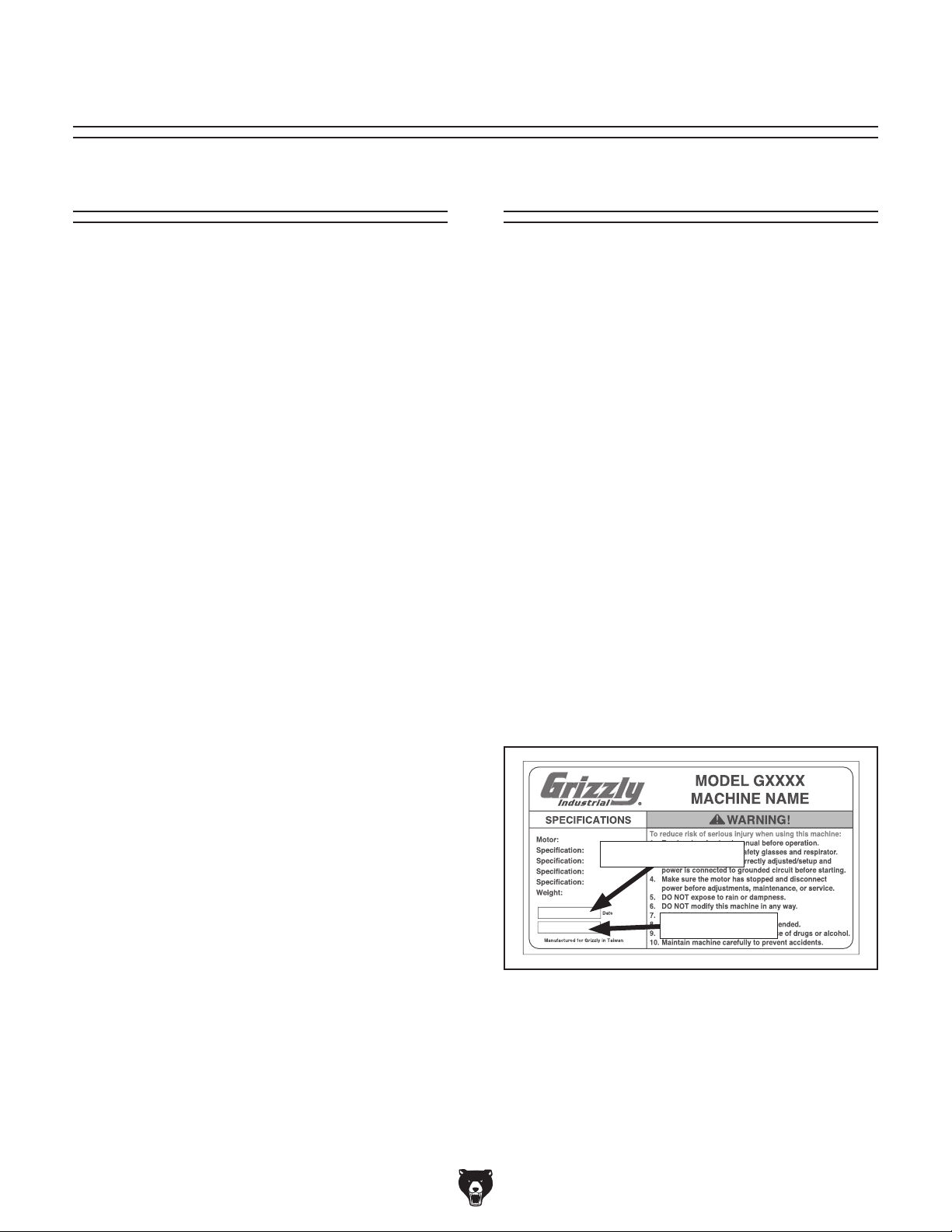
and manufacture date from the
Grizzly Technical Support
1815 W. Battlefield
Springfield, MO 65807
Phone: (570) 546-9663
Email: techsupport@grizzly.com
Grizzly Documentation Manager
P.O. Box 2069
Bellingham, WA 98227-2069
Manual Accuracy
made every effort to be exact with the
sometimes the machine
.
,
e post
manual updates for free
www.grizzly.com.
Manufacture Date and Serial Number
Manufacture Date
Serial Number
-2-
Model G0864 (Mfd. Since 05/19)
Identification
To reduce your risk of
serious injury, read this
entire manual BEFORE
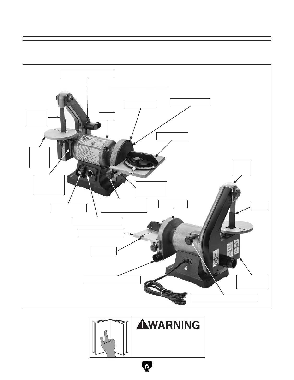
Become familiar with the names and locations of the controls and features shown below to better understand
the instructions in this manual.
Belt Tensioning Lever
Sanding
Belt
Belt
Sander
Table
Belt Sander
Table Lock
Handle
Toggle Switch
Variable-Speed Dial
Disc Sander Table
Sanding Disc
Motor
Angle Scale
Disc Sander Table
Tilt Lock Knob
Miter Gauge
Disc Table
Disc Guard
PSA Sandpaper
Belt
Guard
Platen
Miter Slot
Disc Cover w/Dust Port
Model G0864 (Mfd. Since 05/19)
Belt Cover
w/Dust Port
Belt Tracking Control Knob
using machine.
-3-

Machine Data Sheet
MACHINE DATA
SHEET
Customer Service #: (570) 546-9663 · To Order Call: (800) 523-4777 · Fax #: (800) 438-5901
MODEL G0864 VARIABLE‐SPEED 1" X 30" BELT/ 6" DISC
SANDER
Product Dimensions:
Weight................................................................................................................................................................ 30 lbs.
Width (side-to-side) x Depth (front-to-back) x Height........................................................................... 21 x 12 x 17 in.
Footprint (Length x Width).............................................................................................................................. 10 x 7 in.
Shipping Dimensions:
Type............................................................................................................................................................. Cardboard
Content........................................................................................................................................................... Machine
Weight................................................................................................................................................................ 33 lbs.
Length x Width x Height....................................................................................................................... 19 x 17 x 13 in.
Electrical:
Power Requirement........................................................................................................... 120V, Single-Phase, 60 Hz
Full-Load Current Rating.......................................................................................................................................... 4A
Minimum Circuit Size.............................................................................................................................................. 15A
Connection Type................................................................................................................................... Cord and Plug
Power Cord Included.............................................................................................................................................. Yes
Power Cord Length................................................................................................................................................. 7 ft.
Power Cord Gauge......................................................................................................................................... 18 AWG
Included Plug Type................................................................................................................................................ 5-15
Switch Type.................................................................................................. Toggle Safety Switch w/Removable Key
Motors:
Main
Horsepower............................................................................................................................................. 1/2 HP
Phase............................................................................................................................................ Single-Phase
Amps.............................................................................................................................................................. 4A
Speed................................................................................................................................................ 3400 RPM
Type.......................................................................................................................... Permanent Split Capacitor
Bearings..................................................................................................... Shielded & Permanently Lubricated
Main Specifications:
Belt Sander Info
Sanding Belt Width...................................................................................................................................... 1 in.
Sanding Belt Length.................................................................................................................................. 30 in.
Sanding Belt Speed................................................................................................................ 1900 - 3200 FPM
Table Length.......................................................................................................................................... 5-3/4 in.
Table Width........................................................................................................................................... 5-3/4 in.
Table Thickness....................................................................................................................................... 7/16 in
Table Tilt............................................................................................................................................ 0 - 45 deg.
Max Height of Belt in Vertical Position................................................................................................... 4-1/2 in.
Belt Tension Release Type...................................................................................................................... Spring
Platen Type..................................................................................................................................... POM Plastic
Platen Length........................................................................................................................................ 2-1/4 in.
Platen Width................................................................................................................................................ 1 in.
-4-
Model G0864 (Mfd. Since 05/19)

Disc Sander Info
Disc Diameter.............................................................................................................................................. 6 in.
Disc Speed............................................................................................................................. 2000 - 3450 RPM
Disc Sandpaper Backing Type.................................................................................................................... PSA
Table Length................................................................................................................................................ 8 in.
Table Width........................................................................................................................................... 6-1/8 in.
Table Thickness........................................................................................................................................ 5/8 in.
Table Tilt............................................................................................................................................ 0 - 45 deg.
Construction Materials
Base..................................................................................................................................................... Cast Iron
Table.......................................................................................................................................... Cast Aluminum
Disc............................................................................................................................................ Cast Aluminum
Miter Gauge..................................................................................................................................... ABS Plastic
Paint Type/Finish...................................................................................................................................... Epoxy
Other Related Info
Miter Gauge Slot Width............................................................................................................................. 5/8 in.
Miter Gauge Slot Height......................................................................................................................... 5/16 in.
Number of Dust Ports....................................................................................................................................... 2
Dust Port Size............................................................................................................................ 1-1/2, 1-3/4 in.
Other Specifications:
Country of Origin ................................................................................................................................................ China
Warranty ........................................................................................................................................................... 1 Year
Approximate Assembly & Setup Time ........................................................................................................ 15 Minutes
Serial Number Location ................................................................................................................... Machine ID Label
ISO 9001 Factory .................................................................................................................................................... No
Certified by a Nationally Recognized Testing Laboratory (NRTL) .......................................................................... No
Features:
Variable-Speed Sanding Disc from 2000 - 3400 RPM
Variable-Speed Sanding Belt from 1900 - 3200 FPM
Dedicated Dust Collection Port for Each Side
Uses Standard 1" x 30" Sanding Belts and 6" PSA Sanding Discs
Switch with Removable Safety Key
Tilting Cast-Aluminum Tables
Accessories Included:
Miter Gauge
Dust Port Adapter 1-1/2 in.
Model G0864 (Mfd. Since 05/19)
-5-
SECTION 1: SAFETY
For Your Own Safety, Read Instruction
Manual Before Operating This Machine
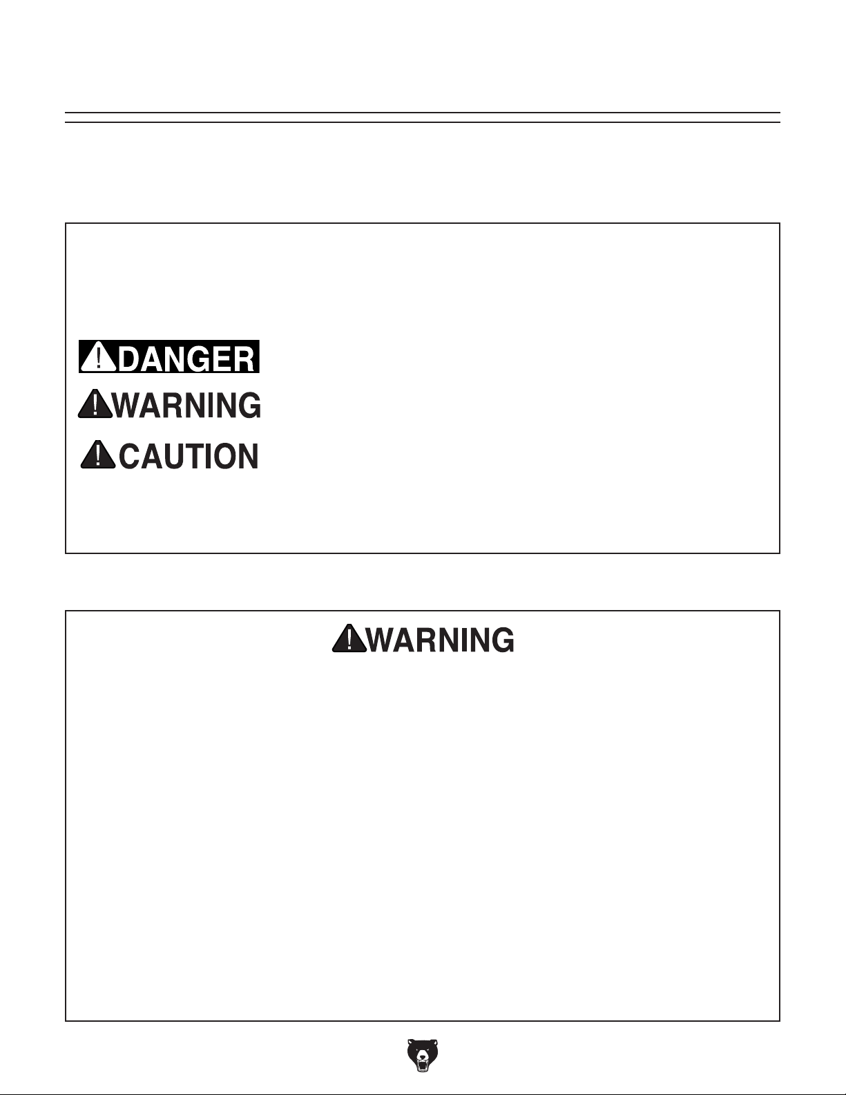
The purpose of safety symbols is to attract your attention to possible hazardous conditions.
This manual uses a series of symbols and signal words intended to convey the level of importance of the safety messages. The progression of symbols is described below. Remember that
safety messages by themselves do not eliminate danger and are not a substitute for proper
accident prevention measures. Always use common sense and good judgment.
Indicates an imminently hazardous situation which, if not avoided,
WILL result in death or serious injury.
Indicates a potentially hazardous situation which, if not avoided,
COULD result in death or serious injury.
Indicates a potentially hazardous situation which, if not avoided,
MAY result in minor or moderate injury. It may also be used to alert
against unsafe practices.
Alerts the user to useful information about proper operation of the
NOTICE
machine to avoid machine damage.
Safety Instructions for Machinery
OWNER’S MANUAL. Read and understand this
owner’s manual BEFORE using machine.
TRAINED OPERATORS ONLY. Untrained operators have a higher risk of being hurt or killed.
Only allow trained/supervised people to use this
machine. When machine is not being used, disconnect power, remove switch keys, or lock-out
machine to prevent unauthorized use—especially
around children. Make your workshop kid proof!
DANGEROUS ENVIRONMENTS. Do not use
machinery in areas that are wet, cluttered, or have
poor lighting. Operating machinery in these areas
greatly increases the risk of accidents and injury.
MENTAL ALERTNESS REQUIRED. Full mental
alertness is required for safe operation of machinery. Never operate under the influence of drugs or
alcohol, when tired, or when distracted.
ELECTRICAL EQUIPMENT INJURY RISKS.
You can be shocked, burned, or killed by touching
live electrical components or improperly grounded
machinery. To reduce this risk, only allow qualified
service personnel to do electrical installation or
repair work, and always disconnect power before
accessing or exposing electrical equipment.
DISCONNECT POWER FIRST.
nect machine from power supply BEFORE making adjustments, changing tooling, or servicing
machine. This prevents an injury risk from unintended startup or contact with live electrical components.
EYE PROTECTION. Always wear ANSI-approved
safety glasses or a face shield when operating or
observing machinery to reduce the risk of eye
injury or blindness from flying particles. Everyday
eyeglasses are NOT approved safety glasses.
Always discon-
-6-
Model G0864 (Mfd. Since 05/19)

WEARING PROPER APPAREL. Do not wear
clothing, apparel or jewelry that can become
entangled in moving parts. Always tie back or
cover long hair. Wear non-slip footwear to reduce
risk of slipping and losing control or accidentally
contacting cutting tool or moving parts.
HAZARDOUS DUST. Dust created by machinery
operations may cause cancer, birth defects, or
long-term respiratory damage. Be aware of dust
hazards associated with each workpiece material. Always wear a NIOSH-approved respirator to
reduce your risk.
HEARING PROTECTION. Always wear hearing protection when operating or observing loud
machinery. Extended exposure to this noise
without hearing protection can cause permanent
hearing loss.
REMOVE ADJUSTING TOOLS. Tools left on
machinery can become dangerous projectiles
upon startup. Never leave chuck keys, wrenches,
or any other tools on machine. Always verify
removal before starting!
USE CORRECT TOOL FOR THE JOB. Only use
this tool for its intended purpose—do not force
it or an attachment to do a job for which it was
not designed. Never make unapproved modifications—modifying tool or using it differently than
intended may result in malfunction or mechanical
failure that can lead to personal injury or death!
AWKWARD POSITIONS. Keep proper footing
and balance at all times when operating machine.
Do not overreach! Avoid awkward hand positions
that make workpiece control difficult or increase
the risk of accidental injury.
CHILDREN & BYSTANDERS. Keep children and
bystanders at a safe distance from the work area.
Stop using machine if they become a distraction.
GUARDS & COVERS. Guards and covers reduce
accidental contact with moving parts or flying
debris. Make sure they are properly installed,
undamaged, and working correctly BEFORE
operating machine.
FORCING MACHINERY. Do not force machine.
It will do the job safer and better at the rate for
which it was designed.
NEVER STAND ON MACHINE. Serious injury
may occur if machine is tipped or if the cutting
tool is unintentionally contacted.
STABLE MACHINE. Unexpected movement during operation greatly increases risk of injury or
loss of control. Before starting, verify machine is
stable and mobile base (if used) is locked.
USE RECOMMENDED ACCESSORIES. Consult
this owner’s manual or the manufacturer for recommended accessories. Using improper accessories will increase the risk of serious injury.
UNATTENDED OPERATION. To reduce the
risk of accidental injury, turn machine OFF and
ensure all moving parts completely stop before
walking away. Never leave machine running
while unattended.
MAINTAIN WITH CARE. Follow all maintenance
instructions and lubrication schedules to keep
machine in good working condition. A machine
that is improperly maintained could malfunction,
leading to serious personal injury or death.
DAMAGED PARTS. Regularly inspect machine
for damaged, loose, or mis-adjusted parts—or
any condition that could affect safe operation.
Immediately repair/replace BEFORE operating
machine. For your own safety, DO NOT operate
machine with damaged parts!
MAINTAIN POWER CORDS. When disconnecting cord-connected machines from power, grab
and pull the plug—NOT the cord. Pulling the cord
may damage the wires inside. Do not handle
cord/plug with wet hands. Avoid cord damage by
keeping it away from heated surfaces, high traffic
areas, harsh chemicals, and wet/damp locations.
EXPERIENCING DIFFICULTIES. If at any time
you experience difficulties performing the intended operation, stop using the machine! Contact our
Technical Support at (570) 546-9663.
Model G0864 (Mfd. Since 05/19)
-7-

Additional Safety for Disc & Belt Sanders
Serious injury or death can occur from fingers, clothing, jewelry, or hair getting pinched/entangled
in rotating disc, belt, spindle or other moving components. Abrasion injuries can occur from
touching moving sandpaper with bare skin. Workpieces thrown by sanding surface can strike
operator or bystanders with moderate force, causing impact injuries. Long-term respiratory
damage can occur from using sander without proper use of a respirator. To reduce the risk of
these hazards, operator or bystanders MUST completely heed the hazards and warnings below.
SANDPAPER DIRECTION. Feeding workpiece
incorrectly can cause it to be thrown from machine,
striking operator or bystanders, or causing your
hands to slip into the moving sandpaper. To reduce
these risks, only sand against direction of sandpaper travel, ensure workpiece is properly supported,
and avoid introducing sharp edges into moving
sandpaper on the leading side of the workpiece.
IN-RUNNING NIP POINTS. The gap between
moving sandpaper and fixed table/support creates
a pinch point for fingers or workpieces; the larger
this gap is, the greater the risk of fingers or workpieces getting caught in it. Minimize this risk by
adjusting table/support to no more than
from sandpaper.
HAND PLACEMENT. Rotating sandpaper can
remove skin quickly. Always keep hands away
from moving sandpaper during operation. Stop
machine to clean table of sawdust and chips.
MINIMUM STOCK DIMENSION. Small workpieces can be aggressively pulled from your hands,
causing contact with sanding surface. Always use
a jig or other holding device when sanding small
workpieces, and keep hands and fingers at least
2" away from sanding surface.
1
⁄16" away
WORKPIECE SUPPORT. Workpiece kickback
can occur with violent force if workpiece is not
properly supported during operation. Always sand
with workpiece firmly against table or another support device.
SANDING DUST. Sanding creates large amounts
of dust that can lead to eye injury or respiratory illness. Reduce your risk by always wearing
approved eye and respiratory protection when
using sander. Never operate without adequate
dust collection system in place and running.
However, dust collection is not a substitute for
using a respirator.
WORKPIECE INSPECTION. Nails, staples, knots,
or other imperfections in workpiece can be dislodged and thrown from sander at a high rate of
speed at people, or cause damage to sandpaper
or sander. Never sand stock that has embedded
foreign objects or questionable imperfections.
SANDPAPER CONDITION. Worn or damaged
sandpaper can fly apart and throw debris at operator, or aggressively grab workpiece, resulting in
subsequent injuries from operator loss of workpiece control. Always inspect sandpaper before
operation and replace if worn or damaged.
FEEDING WORKPIECE. Forcefully jamming
workpiece into sanding surface could cause it to
be grabbed aggressively, pulling hands into sanding surface. Firmly grasp workpiece in both hands
and ease it into sandpaper using light pressure.
AVOIDING ENTANGLEMENT. Becoming entangled in moving parts can cause pinching and
crushing injuries. To avoid these hazards, keep all
guards in place and closed. DO NOT wear loose
clothing, gloves, or jewelry, and tie back long hair.
-8-
WORKPIECE INTEGRITY. Sanding fragile workpieces can result in loss of control, resulting in
abrasion injuries, impact injuries, or damage to
sandpaper. Only sand solid workpieces that can
withstand power sanding forces. Make sure workpiece shape is properly supported; avoid sanding
workpieces without flat bottom surfaces unless
some type of jig is used to maintain support and
control when sanding force is applied.
Model G0864 (Mfd. Since 05/19)
SECTION 2: POWER SUPPLY
Before installing the machine, consider the availability and proximity of the required power supply
circuit. If an existing circuit does not meet the
requirements for this machine, a new circuit must
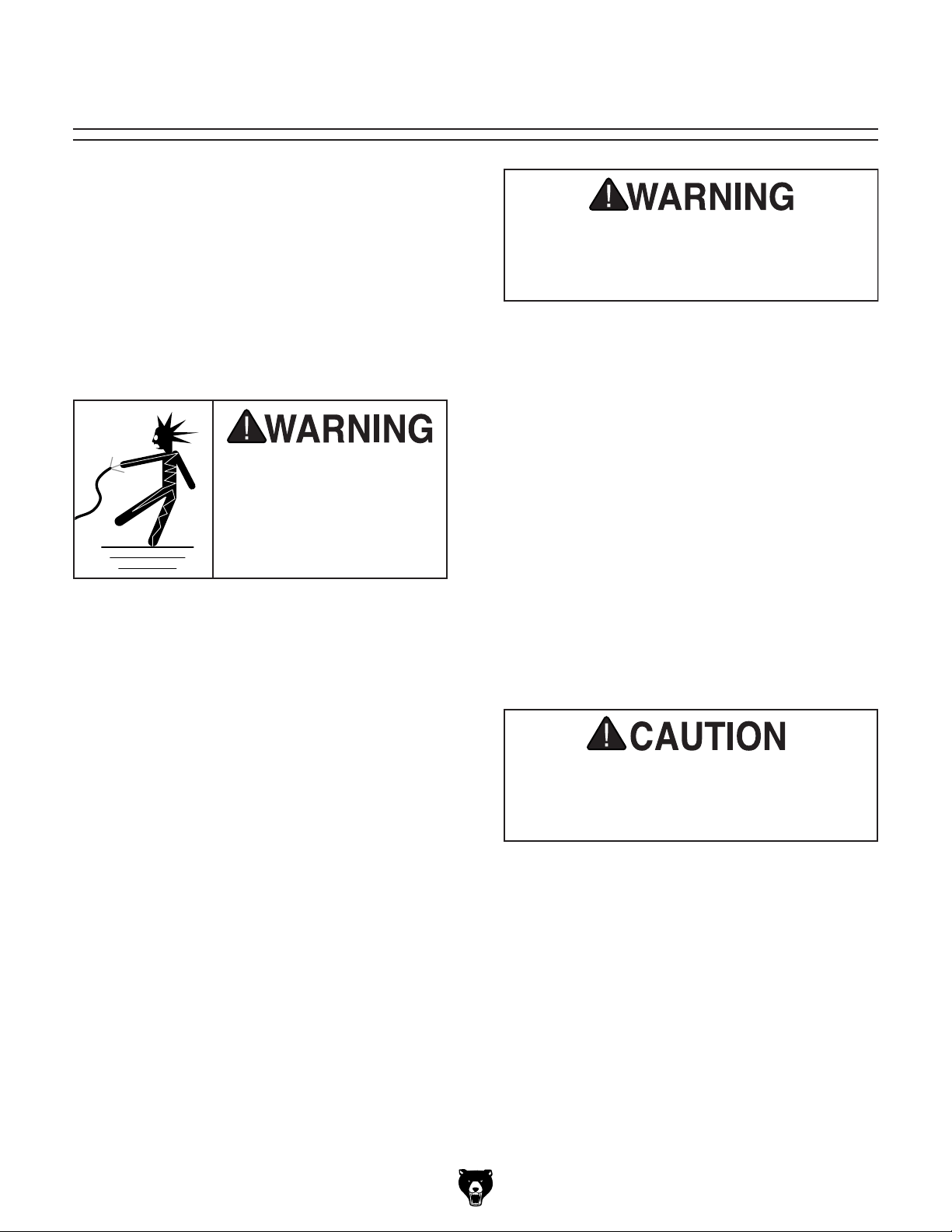
be installed. To minimize the risk of electrocution,
fire, or equipment damage, installation work and
electrical wiring must be done by an electrician or
qualified service personnel in accordance with all
applicable codes and standards.
or equipment damage
may occur if machine is
not properly grounded
and connected to power
The full-load current rating is the amperage a
machine draws at 100% of the rated output power.
On machines with multiple motors, this is the
amperage drawn by the largest motor or sum of all
motors and electrical devices that might operate
at one time during normal operations.
The full-load current is not the maximum amount
of amps that the machine will draw. If the machine
is overloaded, it will draw additional amps beyond
the full-load rating.
If the machine is overloaded for a sufficient length
of time, damage, overheating, or fire may result—
especially if connected to an undersized circuit.
To reduce the risk of these hazards, avoid overloading the machine during operation and make
sure it is connected to a power supply circuit that
meets the specified circuit requirements.
For your own safety and protection of
Note: Circuit requirements in this manual apply to
a dedicated circuit—where only one machine will
be running on the circuit at a time. If machine will
be connected to a shared circuit where multiple
machines may be running at the same time, consult an electrician or qualified service personnel to
ensure circuit is properly sized for safe operation.
A power supply circuit includes all electrical
equipment between the breaker box or fuse panel
in the building and the machine. The power supply circuit used for this machine must be sized to
safely handle the full-load current drawn from the
machine for an extended period of time. (If this
machine is connected to a circuit protected by
fuses, use a time delay fuse marked D.)
This machine is prewired to operate on a power
supply circuit that has a verified ground and meets
the following requirements:
process. DO NOT connect to power until
Availability
Electrocution, fire, shock,
Serious injury could occur if you connect
machine to power before completing setup
instructed later in this manual.
120V Circuit Requirements
Nominal Voltage .................... 110V, 115V, 120V
Cycle .......................................................... 60 Hz
Phase ........................................... Single-Phase
Power Supply Circuit ......................... 15 Amps
supply.
Full-Load Current Rating
Full-Load Current Rating at 120V ....... 4 Amps
Model G0864 (Mfd. Since 05/19)
property, consult an electrician if you are
unsure about wiring practices or electrical
codes in your area.
-9-
 Loading...