

Grizzly G0845P Owner's Manual

MODEL G0845P HEAVY-DUTY
50" ELECTRIC METAL SHEAR
OWNER'S MANUAL
(For models manufactured since 01/18)
COPYRIGHT © MAY, 2018 BY GRIZZLY INDUSTRIAL, INC.
WARNING : NO PORTION OF THIS MANUAL MAY BE REPRODUCED IN ANY SHAPE
OR FORM WITHOUT THE WRITTEN APPROVAL OF GRIZZLY INDUSTRIAL, INC.
#19311KBAB PRINTED IN CHINA
V1. 0 5.18

This manual provides critical safety instructions on the proper setup,
operation, maintenance, and service of this machine/tool. Save this
document, refer to it often, and use it to instruct other operators.
Failure to read, understand and follow the instructions in this manual
may result in fire or serious personal injury—including amputation,
electrocution, or death.
The owner of this machine/tool is solely responsible for its safe use.
This responsibility includes but is not limited to proper installation in
a safe environment, personnel training and usage authorization,
proper inspection and maintenance, manual availability and comprehension, application of safety devices, cutting/sanding/grinding tool
integrity, and the usage of personal protective equipment.
The manufacturer will not be held liable for injury or property damage
from negligence, improper training, machine modifications or misuse.
Some dust created by power sanding, sawing, grinding, drilling, and
other construction activities contains chemicals known to the State
of California to cause cancer, birth defects or other reproductive
harm. Some examples of these chemicals are:
• Lead from lead-based paints.
• Crystalline silica from bricks, cement and other masonry products.
• Arsenic and chromium from chemically-treated lumber.
Your risk from these exposures varies, depending on how often you
do this type of work. To reduce your exposure to these chemicals:
Work in a well ventilated area, and work with approved safety equipment, such as those dust masks that are specially designed to filter
out microscopic particles.

Table of Contents
INTRODUCTION ............................................... 2
Contact Info.................................................... 2
Manual Accuracy ........................................... 2
Identification ................................................... 3
Controls & Components ................................. 4
Machine Data Sheet ...................................... 5
SECTION 1: SAFETY ....................................... 7
Safety Instructions for Machinery .................. 7
Additional Safety for Electric Metal Shears ... 9
SECTION 2: POWER SUPPLY ...................... 10
Disabling & Locking ON/OFF Switch ........... 12
SECTION 3: SETUP ....................................... 13
Needed for Setup ......................................... 13
Unpacking .................................................... 13
Inventory ...................................................... 14
Hardware Recognition Chart ....................... 15
Cleanup ........................................................ 16
Site Considerations ...................................... 17
Lifting & Placing ........................................... 18
Leveling ........................................................ 19
Anchoring to Floor ....................................... 19
Assembly ..................................................... 20
Power Connection........................................ 21
Test Run ...................................................... 22
SECTION 4: OPERATIONS ........................... 25
Operation Overview ..................................... 25
Cutting Tips .................................................. 26
Cutting Procedure ........................................ 26
Using Work Stops ........................................ 28
SECTION 5: ACCESSORIES ......................... 30
SECTION 6: MAINTENANCE ......................... 32
Schedule ...................................................... 32
Cleaning & Protecting .................................. 32
Lubrication ................................................... 32
SECTION 7: SERVICE ................................... 36
Troubleshooting ........................................... 36
Adjusting Blade Gap .................................... 38
Reversing & Replacing Blades .................... 41
Adjusting Gibs .............................................. 43
Squaring Side Work Stops........................... 44
Squaring Rear Work Stop ............................ 45
Adjusting Hold-Down Clamp ........................ 45
Tensioning & Replacing V-Belts .................. 46
Adjusting Foot-Pedal Time Delay ................ 48
Adjusting Blade-Travel Limit Switch ............ 48
SECTION 8: WIRING ...................................... 49
Wiring Safety Instructions ............................ 49
Electrical Components ................................. 50
Electrical Box Wiring Diagram ..................... 51
Control Panel Wiring Diagram ..................... 52
Foot Pedestal & Motor Wiring ...................... 53
SECTION 9: PARTS ....................................... 54
Frame ........................................................... 54
Frame Parts List .......................................... 55
Upper Blade-Motor-Gearbox Parts .............. 56
Blade Guards & Hold-Down Clamp Parts .... 58
Rear Work Stop Parts .................................. 59
Support Rods Parts ..................................... 60
Electrical Parts ............................................. 61
Labels & Cosmetics ..................................... 62
WARRANTY & RETURNS ............................. 65
Like all machinery there is potential danger
when operating this machine. Accidents
are frequently caused by lack of familiarity
or failure to pay attention. Use this machine
with respect and caution to decrease the
risk of operator injury. If normal safety precautions are overlooked or ignored, serious personal injury may occur.
No list of safety guidelines can be complete. Every shop environment is different.
Always consider safety first, as it applies
to your individual working conditions. Use
this and other machinery with caution and
respect. Failure to do so could result in
serious personal injury, damage to equipment, or poor work results.
INTRODUCTION
We stand behind our machines! If you have questions or need help, contact us with the information
below. Before contacting, make sure you get the
serial number
machine ID label. This will help us help you faster.
We want your feedback on this manual. What did
you like about it? Where could it be improved?
Please take a few minutes to give us feedback.
We are proud to provide a high-quality owner’s
manual with your new machine!
We
instructions, specifications, drawings, and photographs
in this manual. Sometimes we make mistakes, but
our policy of continuous improvement also means
that
you receive is
slightly different than shown in the manual
If you find this to be the case, and the difference
between the manual and machine leaves you
confused or unsure about something
check our
website for an updated version. W
current
manuals and
on our web-
site at
Alternatively, you can call our Technical Support
for help. Before calling, make sure you write down
the
from
the machine ID label (see below). This information
is required for us to provide proper tech support,
and it helps us determine if updated documentation is available for your machine.
Contact Info
and manufacture date from the
Grizzly Technical Support
1815 W. Battlefield
Springfield, MO 65807
Phone: (570) 546-9663
Email: techsupport@grizzly.com
Grizzly Documentation Manager
P.O. Box 2069
Bellingham, WA 98227-2069
Email: manuals@grizzly.com
Manual Accuracy
made every effort to be exact with the
sometimes the machine
.
,
e post
manual updates for free
www.grizzly.com.
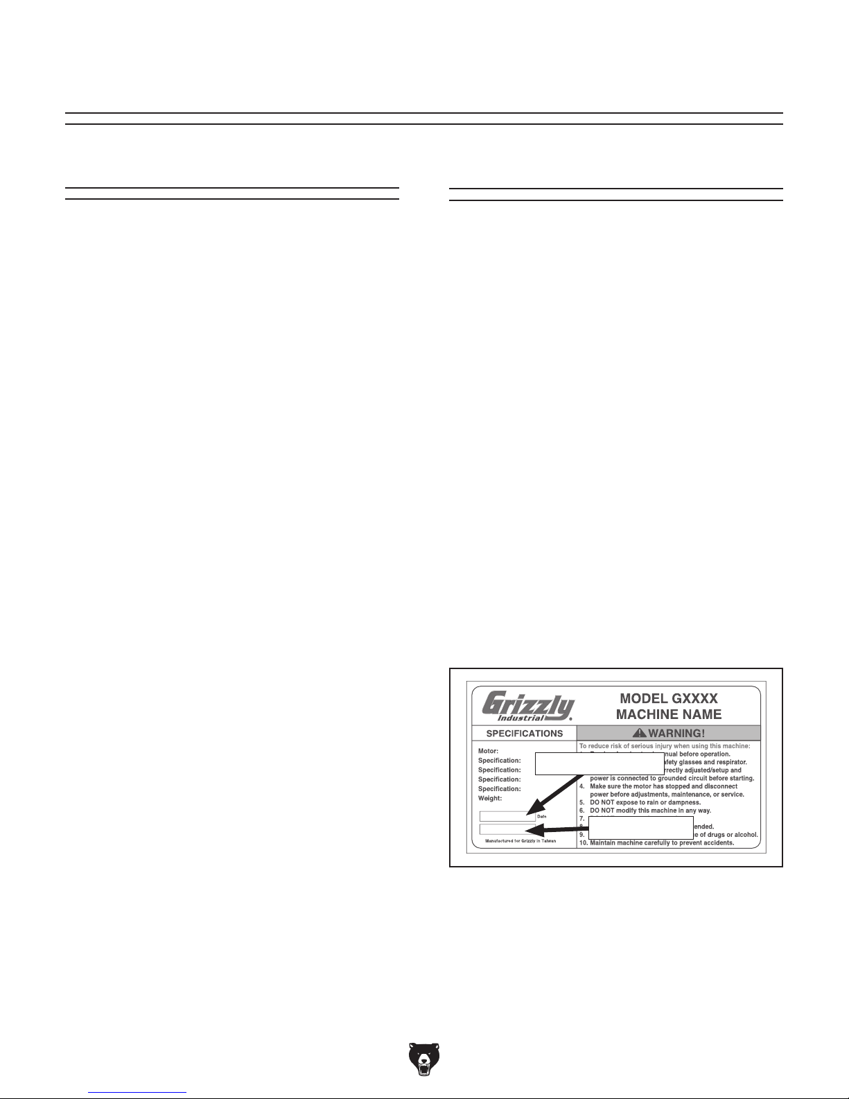
Manufacture Date and Serial Number
Manufacture Date
Serial Number
-2-
Model G0845P (Mfd. Since 01/18)
To reduce your risk of
serious injury, read this
entire manual BEFORE
Identification
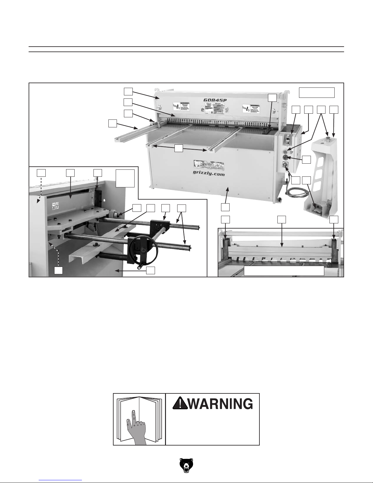
Become familiar with the names and locations of the controls and features shown below to better understand
the instructions in this manual.
D
C
B
A
E
V
W
V
Rear
View
U
T S
R
Q
P
F
O
Front View
G I J
H
K
M
L
N
U
A. Left Work Stop
B. Adjustable Stop Block
C. Blade Finger Guard
D. Blade Cover
E. Workpiece Support Rods
F. Right Work Stop
G. Control Panel
H. Electrical Box
I. Emergency Stop Buttons
J. Foot Pedestal
K. Blade Light Switch
L. ON/OFF Switch w/Lockout
X
M. Foot Pedal
N. Right Blade Guide
O. Hold-Down Clamp
P. Left Blade Guide
Q. Front Cover
R. Rear Work Stop Support Rods
S. Rear Work Stop Assembly
T. Rear Work Stop
U. Blade Gap Adjusters
V. Blade Gibs
W. Upper Blade Frame
X. Rear Cover
using machine.
(Safety Covers Removed)
Model G0845P (Mfd. Since 01/18)
-3-
Controls & Components
Basic Controls
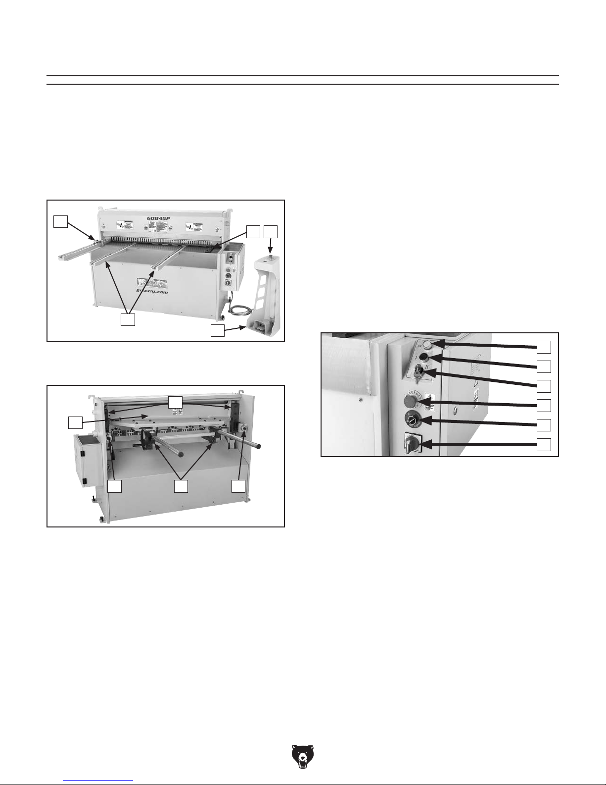
Refer to the following figures and descriptions to
become familiar with the basic controls and components of this machine. Understanding these
items and how they work will help you understand
the rest of the manual and minimize your risk of
injury when operating this machine.
A
E
B
C
D
Figure 1. G0845P controls and components
(front).
F
E. Emergency Stop Button: Turns machine
OFF when pressed. Twist clockwise to reset.
F. Blade Guides: Control position of upper
blade relative to lower blade.
G. Upper Blade Frame: Holds upper blade and
supports rear work stop assembly.
H. Blade Gap Adjusters: Change blade gap
to account for workpiece gauge and material
hardness. ALWAYS set gap adjusters equally.
I. Rear Work Stop Assembly: Allows opera-
tor to set shear for multiple cuts of the same
depth.
Control Panel
J
K
L
M
G
H
Figure 2. G0845P basic controls (rear).
A. Left Work Stop w/Stop Block: Helps the
operator square large workpieces. Scale
shows distance to blades. Adjustable stop
block allows repeated cuts of same depth.
B. Right Work Stop: Lets the operator square
smaller workpieces for left-hand cuts.
C. Workpiece Support Rods: Provide support
for large workpieces. Scales show distance
to blades.
D. Foot Pedestal: Contains foot pedal to oper-
ate blade, and Emergency Stop button.
I H
N
O
Figure 3. G0845P control panel.
J. Power Indicator: Illuminates when machine
is connected to power.
K. Jog Button: Engages shear when pushed in;
disengages shear when released.
L. Shear Switch: Use to select jog operation
(left) or foot-switch operation (right).
M. EMERGENCY STOP Button: Turns machine
OFF when pressed. Twist clockwise to reset.
N. Shadow Lighter: Turn right to turn light ON
behind cutting guard. Turn left to turn OFF.
O. ON/OFF Switch w/Lockout: Turn right to
turn machine ON. Turn left to turn machine
OFF. To disable and lock machine, turn
switch to OFF, then press white tab in to
install padlock through center slot.
-4-
Model G0845P (Mfd. Since 01/18)

MACHINE DATA
SHEET
Customer Service #: (570) 546-9663 · To Order Call: (800) 523-4777 · Fax #: (800) 438-5901
MODEL G0845P HEAVY‐DUTY 50" ELECTRIC METAL
SHEAR ‐ POLAR BEAR SERIES
Product Dimensions:
Weight............................................................................................................................................................ 3197 lbs.
Width (side-to-side) x Depth (front-to-back) x Height..................................................................... 72-1/2 x 80 x 48 in.
Footprint (Length x Width)............................................................................................................... 28-1/2 x 66-1/2 in.
Space Required for Full Range of Movement (Width x Depth).................................................................... 96 x 80 in.
Shipping Dimensions:
Type.......................................................................................................................................................... Wood Crate
Content........................................................................................................................................................... Machine
Weight............................................................................................................................................................ 3748 lbs.
Length x Width x Height....................................................................................................................... 79 x 45 x 63 in.
Must Ship Upright................................................................................................................................................... Yes
Electrical:
Power Requirement................................................................................................................... 220V, 3-Phase, 60 Hz
Full-Load Current Rating..................................................................................................................................... 20.7A
Minimum Circuit Size.............................................................................................................................................. 30A
Connection Type............................................................................................................................................ Hardwire
Switch Type...................................................................... Foot-Operated ON/OFF Switch w/External Safety Padlock
Motors:
Main
Horsepower............................................................................................................................................. 7.5 HP
Phase.................................................................................................................................................... 3-Phase
Amps......................................................................................................................................................... 20.7A
Speed................................................................................................................................................ 1720 RPM
Type........................................................................................................................... TEFC w/Integrated Brake
Power Transfer ............................................................................................................................... V-Belt Drive
Bearings........................................................................................................ Sealed & Permanently Lubricated
Centrifugal Switch/Contacts Type................................................................................................................ N/A
Main Specifications:
Capacities
Maximum Width......................................................................................................................................... 50 in.
Maximum Thickness Mild Steel.......................................................................................................... 10 Gauge
Maximum Thickness at Full Width Mild Steel..................................................................................... 10 Gauge
Aluminum............................................................................................................................................ 10 Gauge
Maximum Beam Lift................................................................................................................... 1/2 - 1-13/16 in.
Bed Height Above Floor...................................................................................................................... 31-1/2 in.
Working Height.................................................................................................................................... 31-1/2 in.
Front Stop Scale Range..................................................................................................... 3-15/16 - 39-5/16 in.
Rear Stop Scale Range.................................................................................................................. 0 - 25-5/8 in.
Model G0845P (Mfd. Since 01/18)
-5-

Construction
Frame......................................................................................................................................................... Steel
Shear Table................................................................................................................................................ Steel
Shear Hold-Down Clamp............................................................................................................................ Steel
Shear Blades.............................................................................................................................................. Steel
Shear Blade Type...................................................................................................................... Hardened Alloy
Other Specifications:
Country of Origin ................................................................................................................................................ China
Warranty ........................................................................................................................................................... 1 Year
Approximate Assembly & Setup Time ............................................................................................................. 2 Hours
Serial Number Location ................................................................................................................... Machine ID Label
ISO 9001 Factory .................................................................................................................................................. Yes
Certified by a Nationally Recognized Testing Laboratory (NRTL) .......................................................................... No
Features:
Remote On/Off Foot Pedal Control
Reversible, Hardened Steel Alloy Cutting Shear Dies for Extended Life
Adjustable Front and Rear Stop Scales
Hand and Foot-Pedal Operation
Super-Quiet Operation
Built-In, Non-Marring Hold-Down Clamp
Shadow Light
-6-
Model G0845P (Mfd. Since 01/18)
SECTION 1: SAFETY
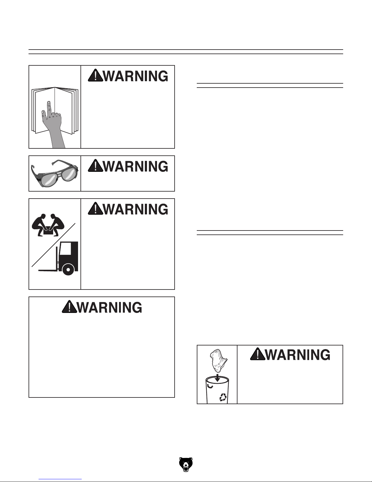
For Your Own Safety, Read Instruction
Manual Before Operating This Machine
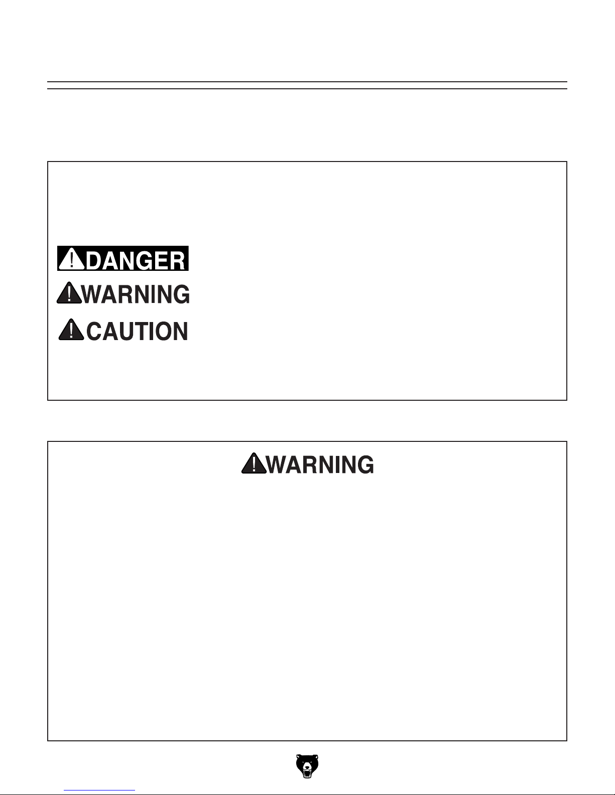
The purpose of safety symbols is to attract your attention to possible hazardous conditions.
This manual uses a series of symbols and signal words intended to convey the level of importance of the safety messages. The progression of symbols is described below. Remember that
safety messages by themselves do not eliminate danger and are not a substitute for proper
accident prevention measures. Always use common sense and good judgment.
Indicates an imminently hazardous situation which, if not avoided,
WILL result in death or serious injury.
Indicates a potentially hazardous situation which, if not avoided,
COULD result in death or serious injury.
Indicates a potentially hazardous situation which, if not avoided,
MAY result in minor or moderate injury. It may also be used to alert
against unsafe practices.
This symbol is used to alert the user to useful information about
NOTICE
proper operation of the machine.
Safety Instructions for Machinery
OWNER’S MANUAL. Read and understand this
owner’s manual BEFORE using machine.
TRAINED OPERATORS ONLY. Untrained operators have a higher risk of being hurt or killed.
Only allow trained/supervised people to use this
machine. When machine is not being used, disconnect power, remove switch keys, or lock-out
machine to prevent unauthorized use—especially
around children. Make your workshop kid proof!
DANGEROUS ENVIRONMENTS. Do not use
machinery in areas that are wet, cluttered, or have
poor lighting. Operating machinery in these areas
greatly increases the risk of accidents and injury.
MENTAL ALERTNESS REQUIRED. Full mental
alertness is required for safe operation of machinery. Never operate under the influence of drugs or
alcohol, when tired, or when distracted.
ELECTRICAL EQUIPMENT INJURY RISKS. You
can be shocked, burned, or killed by touching live
electrical components or improperly grounded
machinery. To reduce this risk, only allow qualified
service personnel to do electrical installation or
repair work, and always disconnect power before
accessing or exposing electrical equipment.
DISCONNECT POWER FIRST.
nect machine from power supply BEFORE making
adjustments, changing tooling, or servicing machine.
This prevents an injury risk from unintended startup
or contact with live electrical components.
EYE PROTECTION. Always wear ANSI-approved
safety glasses or a face shield when operating or
observing machinery to reduce the risk of eye
injury or blindness from flying particles. Everyday
eyeglasses are NOT approved safety glasses.
Always discon-
Model G0845P (Mfd. Since 01/18)
-7-

WEARING PROPER APPAREL. Do not wear
clothing, apparel or jewelry that can become
entangled in moving parts. Always tie back or
cover long hair. Wear non-slip footwear to reduce
risk of slipping and losing control or accidentally
contacting cutting tool or moving parts.
HAZARDOUS DUST. Dust created by machinery
operations may cause cancer, birth defects, or
long-term respiratory damage. Be aware of dust
hazards associated with each workpiece material. Always wear a NIOSH-approved respirator to
reduce your risk.
HEARING PROTECTION. Always wear hearing protection when operating or observing loud
machinery. Extended exposure to this noise
without hearing protection can cause permanent
hearing loss.
REMOVE ADJUSTING TOOLS. Tools left on
machinery can become dangerous projectiles
upon startup. Never leave chuck keys, wrenches,
or any other tools on machine. Always verify
removal before starting!
USE CORRECT TOOL FOR THE JOB. Only use
this tool for its intended purpose—do not force
it or an attachment to do a job for which it was
not designed. Never make unapproved modifications—modifying tool or using it differently than
intended may result in malfunction or mechanical
failure that can lead to personal injury or death!
AWKWARD POSITIONS. Keep proper footing
and balance at all times when operating machine.
Do not overreach! Avoid awkward hand positions
that make workpiece control difficult or increase
the risk of accidental injury.
CHILDREN & BYSTANDERS. Keep children and
bystanders at a safe distance from the work area.
Stop using machine if they become a distraction.
GUARDS & COVERS. Guards and covers reduce
accidental contact with moving parts or flying
debris. Make sure they are properly installed,
undamaged, and working correctly BEFORE
operating machine.
FORCING MACHINERY. Do not force machine.
It will do the job safer and better at the rate for
which it was designed.
NEVER STAND ON MACHINE. Serious injury
may occur if machine is tipped or if the cutting
tool is unintentionally contacted.
STABLE MACHINE. Unexpected movement during operation greatly increases risk of injury or
loss of control. Before starting, verify machine is
stable and mobile base (if used) is locked.
USE RECOMMENDED ACCESSORIES. Consult
this owner’s manual or the manufacturer for recommended accessories. Using improper accessories will increase the risk of serious injury.
UNATTENDED OPERATION. To reduce the
risk of accidental injury, turn machine OFF and
ensure all moving parts completely stop before
walking away. Never leave machine running
while unattended.
MAINTAIN WITH CARE. Follow all maintenance
instructions and lubrication schedules to keep
machine in good working condition. A machine
that is improperly maintained could malfunction,
leading to serious personal injury or death.
DAMAGED PARTS. Regularly inspect machine
for damaged, loose, or mis-adjusted parts—or
any condition that could affect safe operation.
Immediately repair/replace BEFORE operating
machine. For your own safety, DO NOT operate
machine with damaged parts!
MAINTAIN POWER CORDS. When disconnecting cord-connected machines from power, grab
and pull the plug—NOT the cord. Pulling the cord
may damage the wires inside. Do not handle
cord/plug with wet hands. Avoid cord damage by
keeping it away from heated surfaces, high traffic
areas, harsh chemicals, and wet/damp locations.
EXPERIENCING DIFFICULTIES. If at any time
you experience difficulties performing the intended operation, stop using the machine! Contact our
Technical Support at (570) 546-9663.
-8-
Model G0845P (Mfd. Since 01/18)

Additional Safety for Electric Metal Shears
Serious cuts, amputation, or death can occur from contact with the shear blades during
operation, adjustment, or maintenance. To reduce this risk, anyone using this machine MUST
completely heed the hazards and warnings below.
FINGER AMPUTATION. The shear blades or hold-
down can easily pinch, crush, or amputate fingers or
other body parts. Always keep hands, fingers, and
other body parts away from blades and hold-down
(point-of-operation) during shearing operations.
GUARDS. Keep all guards in place, properly
positioned, and in working order. Never operate
shear with blade guard removed. If blade guard is
removed or not properly positioned, fingers may
accidentally be cut or amputated by shear blades.
Always position guard just high enough to allow
workpiece to enter, but not fingers.
CAPACITY. Exceeding cutting capacity of shear
may result in breakage or machine damage that
ejects dangerous metal debris at operator or
bystanders. Only use sheet metal within the rated
capacity of this shear (refer to the Machine Data
Sheet).
PROPER WORKPIECE MATERIAL. Shear is only
intended for cutting ferrous and non-ferrous mild
sheet metal or flat stock. Do not attempt to cut
round metal stock, glass, wood, drywall, backer
board, plywood, or other material not intended for
this machine. Cutting incorrect materials can produce unexpected results, which increases risk of
injury, and may result in damage to machine.
USE OF HAND TOOLS. Hand tools are intended
for placing and removing materials from shear
point-of-operation. Use of hand tools is intended to
prevent need for operator to place hands or fingers
within point-of-operation. Always use hand tools
to place or remove any workpiece within point-ofoperation, in conjunction with all blade guards.
WORK AREA. Provide sufficient clearance around
machine to permit safe use by regular operators and performance of maintenance procedures.
Keep work area clear of materials or substances
that may create a slip, trip, or fall hazard.
SHARP METAL EDGES. The sharp edges of
sheet metal can easily cut fingers, hands, and
other body parts. Always wear heavy leather
gloves when handling sheet metal. Always chamfer and deburr sharp workpiece edges.
OPERATOR POSITION. Avoid awkward body
and hand positions where a sudden slip could
cause your hand or body to enter point-of-operation or make accidental contact with shear blades.
MAINTENANCE/SERVICE. Always disconnect
machine from power and wait for all moving parts
to come to a complete stop before performing any
adjustments, service, or maintenance.
BLADE CONDITION. Sharp, undamaged, and
properly adjusted blades will reduce risk of injury
from breakage or sharp burrs left on workpiece.
Always keep blades properly adjusted and sharp.
SHEAR BLADE ADJUSTMENT. When adjusting or replacing shear blades, always disconnect
machine from power, wear heavy leather gloves to
protect hands, and wear safety glasses to protect
eyes.
CHECK MACHINE. Before using machine, carefully check components for wear that could affect
operation. Check blade alignment and gib play,
and ensure guards are properly installed. DO NOT
operate machine until all defects are corrected.
STRAY SHEET METAL PIECES. Sheet metal
cut-off pieces left on the floor can easily slide
under foot and cause falling injuries. Always
remove cut-off sheet metal pieces from the floor
after operation. Keep work area clean.
Model G0845P (Mfd. Since 01/18)
-9-

SECTION 2: POWER SUPPLY
Before installing the machine, consider the availability and proximity of the required power supply
circuit. If an existing circuit does not meet the
requirements for this machine, a new circuit must
be installed. To minimize the risk of electrocution,
fire, or equipment damage, installation work and
electrical wiring must be done by an electrician or
qualified service personnel in accordance with all
applicable codes and standards.
or equipment damage
may occur if machine is
not properly grounded
and connected to power
The full-load current rating is the amperage a
machine draws at 100% of the rated output power.
On machines with multiple motors, this is the
amperage drawn by the largest motor or sum of all
motors and electrical devices that might operate
at one time during normal operations.
The full-load current is not the maximum amount
of amps that the machine will draw. If the machine
is overloaded, it will draw additional amps beyond
the full-load rating.
If the machine is overloaded for a sufficient length
of time, damage, overheating, or fire may result—
especially if connected to an undersized circuit.
To reduce the risk of these hazards, avoid overloading the machine during operation and make
sure it is connected to a power supply circuit that
meets the specified circuit requirements.
This machine is prewired to operate on a power
supply circuit that has a verified ground and meets
the following requirements:
Note: Circuit requirements in this manual apply to
a dedicated circuit—where only one machine will
be running on the circuit at a time. If machine will
be connected to a shared circuit where multiple
machines may be running at the same time, consult an electrician or qualified service personnel to
ensure circuit is properly sized for safe operation.
For your own safety and protection of
A power supply circuit includes all electrical
equipment between the breaker box or fuse panel
in the building and the machine. The power supply circuit used for this machine must be sized to
safely handle the full-load current drawn from the
machine for an extended period of time. (If this
machine is connected to a circuit protected by
fuses, use a time delay fuse marked D.)
Availability
Electrocution, fire, shock,
supply.
Full-Load Current Rating
Circuit Information
property, consult an electrician if you are
unsure about wiring practices or electrical
codes in your area.
Full-Load Current Rating at 220V .. 20.7 Amps
-10 -
Circuit Requirements for 220V
Nominal Voltage ................... 220V, 230V, 240V
Cycle .......................................................... 60 Hz
Phase .................................................... 3-Phase
Power Supply Circuit ......................... 30 Amps
Model G0845P (Mfd. Since 01/18)
Since this machine must be permanently connected to the power supply, an extension cord
cannot be used.
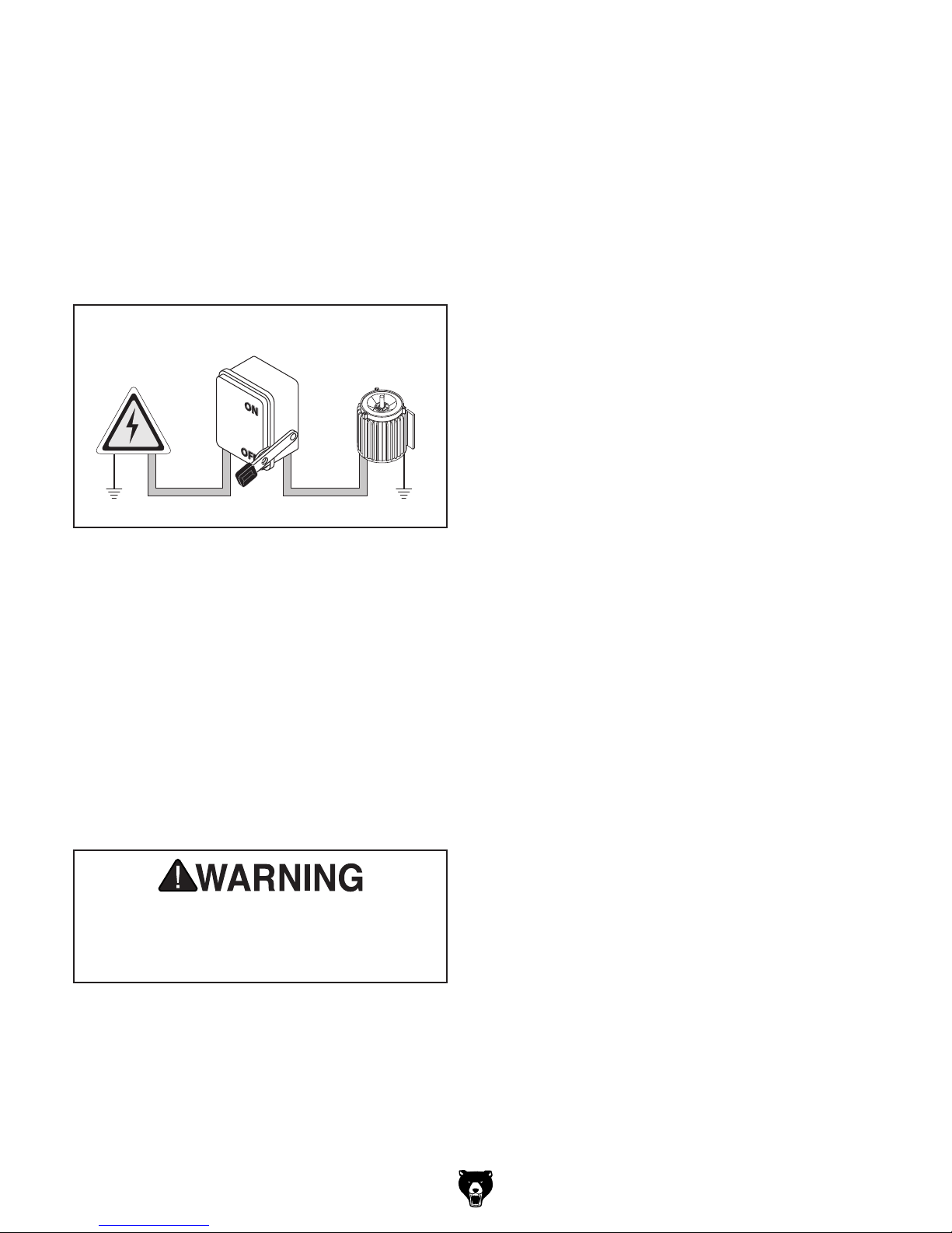
Connection Type
A permanently connected (hardwired) power supply is typically installed with wires running through
mounted and secured conduit. A disconnecting
means, such as a locking switch (see following
figure), must be provided to allow the machine
to be disconnected (isolated) from the power
supply when required. This installation must be
performed by an electrician in accordance with all
applicable electrical codes and ordinances.
Serious injury could occur if you connect
process. DO NOT connect to power until
In the event of a malfunction or breakdown,
grounding provides a path of least resistance
for electrical current to reduce the risk of electric
shock. A permanently connected machine must
be connected to a grounded metal permanent wiring system; or to a system having an equipmentgrounding conductor. All grounds must be verified
and rated for the electrical requirements of the
machine. Improper grounding can increase the
risk of electric shock!
Locking
Disconnect Switch
Power
Source
Extension Cords
Phase Converters
Avoid using a static phase converter to supply
3-Phase power for this machine, as it could damage or decrease the life of sensitive electrical
components. If you must use a phase converter,
only use a rotary phase converter that is sized
at least 50% larger than the HP rating of this
machine. If using a phase converter to supply
power, only connect the manufactured leg or "wild
Machine
ConduitConduit
wire" to the "L3" terminal (see location on Page
51). The L3 terminal can handle power fluctua-
tions because it is wired directly to the motor.
Ground
Figure 4. Typical setup of a permanently
connected machine.
Ground
Grounding Instructions
machine to power before completing setup
instructed later in this manual.
Model G0845P (Mfd. Since 01/18)
-11-
Children or untrained people can be
. This
To help prevent unsupervised operation,
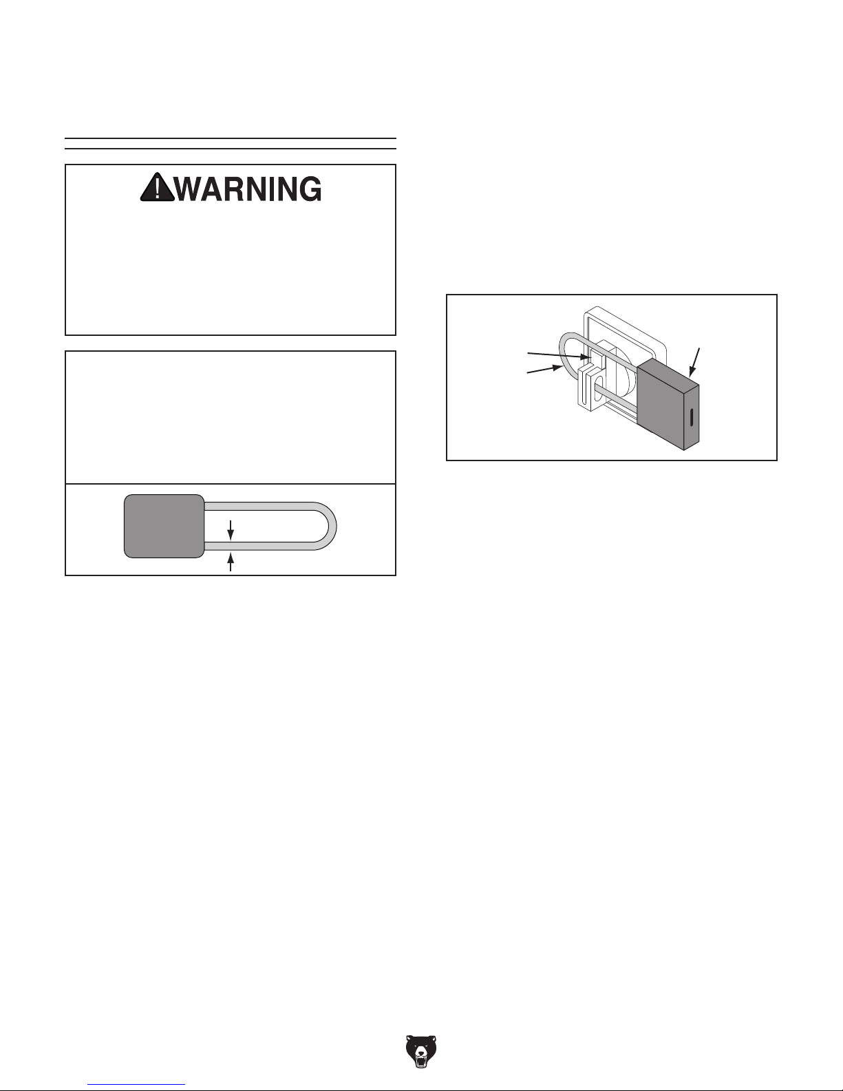
Disabling & Locking
The machine can be disabled and locked by
pushing the tab in and inserting a padlock through
the rotary ON/OFF switch, as shown. Locking the
switch in this manner can prevent unauthorized
operation of the machine, which is especially
important if the machine is not stored inside an
access-restricted building.
IMPORTANT:
a padlock only restricts switch function. It is not
a substitute for disconnecting power from the
machine when adjusting or servicing.
ON/OFF Switch
seriously injured by this machine
risk increases with unsupervised operation.
disable and lock the switch before leaving
machine unattended! Place key in a wellhidden or secure location.
NOTICE
The padlock shaft diameter is important to
the disabling function of the switch. With
any padlock used to lock the switch, test
the switch after installation to ensure that it
is properly disabled.
Locking the ON/OFF switch with
Tab
Shaft
Figure 6. ON/OFF switch disabled by a padlock.
Padlock
Figure 5. Minimum lock shaft requirements.
-12-
Model G0845P (Mfd. Since 01/18)
SECTION 3: SETUP
This machine was carefully packaged for safe
transport. When unpacking, separate all enclosed
items from packaging materials and inspect them
for shipping damage.
,
please
IMPORTANT:
you are completely satisfied with the machine and
have resolved any issues between Grizzly or the
shipping agent. You MUST have the original pack-
aging to file a freight claim. It is also extremely
helpful if you need to return your machine later.
Keep children and pets away
from plastic bags or packing
materials shipped with this
get help from other people
The following items are needed, but not included,
for the setup/assembly of this machine.
Needed for Setup
This machine presents
serious injury hazards
to untrained users. Read
through this entire manual to become familiar with
the controls and operations before starting the
machine!
Wear safety glasses during
the entire setup process!
Description Qty
Precision Level .................................................. 1
Assistants ............................................ At Least 2
Safety Glasses (per person) .........................1 Ea
Solvent/Cleaner (Page 16) ................ As Needed
Shop Rags ......................................... As Needed
Wrenches 25, 18, 17mm ...............................1 Ea
Brass Hammer .................................................. 1
Forklift ................................................................ 1
Floor Mounting Hardware .................. As Needed
HEAVY LIF T!
Straining or crushing injury
may occur from improperly
lifting machine or some of
its parts. To reduce this risk,
and use a forklift (or other
lifting equipment) rated for
weight of this machine.
This is an extremely heavy machine! Serious
personal injury or death may occur if safe
lifting and moving methods are not followed. To be safe, you will need assistance
and power equipment when moving the
shipping crate and removing the machine
from the crate. Seek assistance from a
professional rigger if you are unsure about
your abilities or maximum load ratings of
your lifting equipment.
Unpacking
If items are damaged
call us immediately at (570) 546-9663.
Save all packaging materials until
SUFFOCATION HAZARD!
machine. Discard immediately.
Model G0845P (Mfd. Since 01/18)
-13-
Inventory
The following is a list of items shipped with your
machine. Before beginning setup, lay these items
out and inventory them.
If any non-proprietary parts are missing (e.g. a
nut or a washer), we will gladly replace them; or
for the sake of expediency, replacements can be
obtained at your local hardware store.
A
B
NOTICE
If you cannot find an item on this list, carefully check around/inside the machine and
packaging materials. Often, these items get
lost in packaging materials while unpacking or they are pre-installed at the factory.
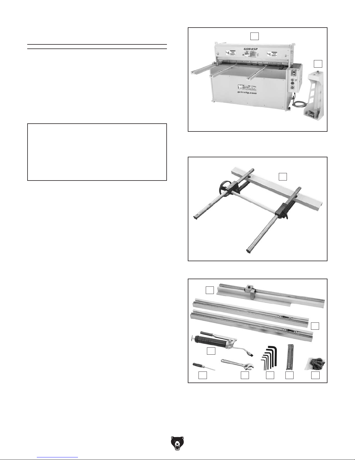
Box 1 (Figures 7–9) Qty
A. Electric Shear ............................................. 1
B. Foot Pedestal Assembly ............................. 1
C. Rear Work Stop Assembly ......................... 1
D. Left Side Stop w/Flip Stop .......................... 1
E. Workpiece Support Rods ........................... 2
F. Grease Gun ................................................ 1
G. Flat Head Screwdriver #2 ........................... 1
H. Adjustable Wrench ..................................... 1
I. Hex Wrench Set 3, 4, 5, 6, 8, 10mm .....1 Ea
J. Feeler Gauge Set ....................................... 1
K. Hardware Bag
—Hex Bolts M16-2 x 25 ............................. 2
— Dock Washers 16 x 44 x 6mm ............... 2
—Cap Screws M8-1.25 x 16....................... 6
Figure 7. G0845P electric shear and foot
pedestal assembly.
C
Figure 8. G0845P rear work stop assembly.
D
-14-
E
F
G H I J K
Figure 9. G0845P inventory.
Model G0845P (Mfd. Since 01/18)
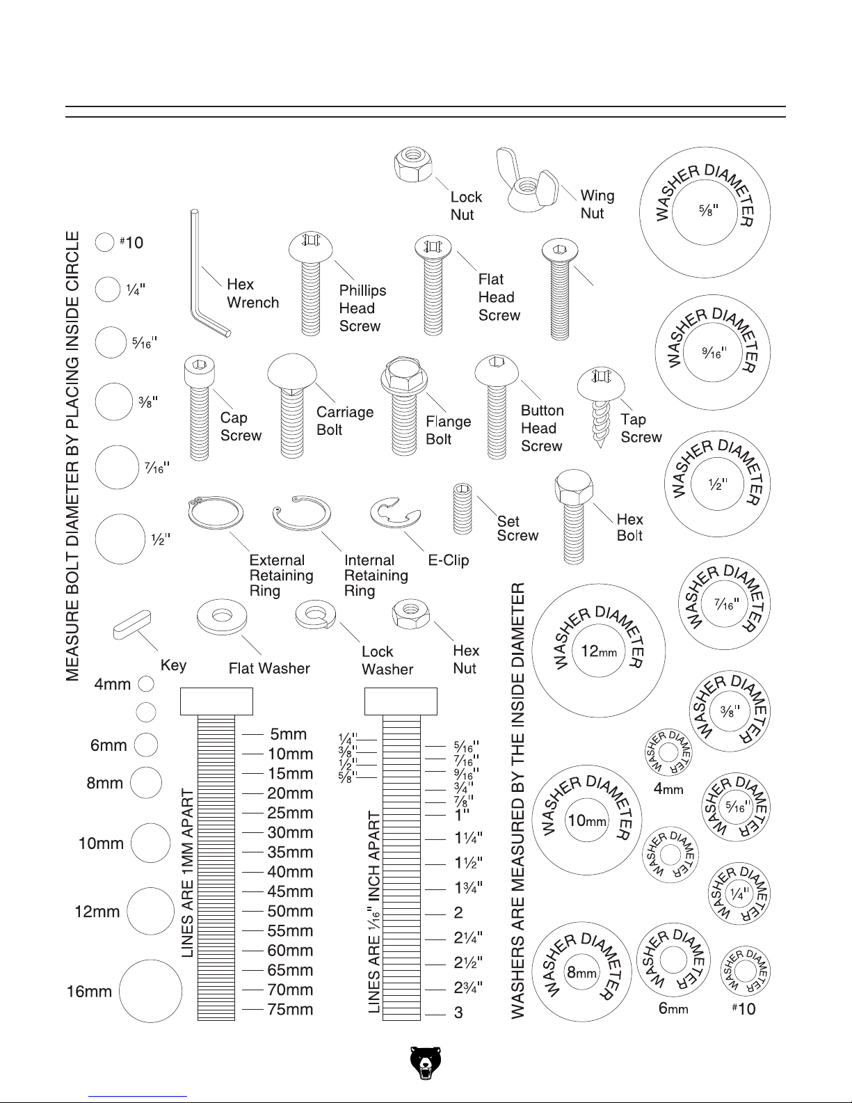
Hardware Recognition Chart
USE THIS CHART TO MATCH UP
HARDWARE DURING THE INVENTORY
AND ASSEMBLY PROCESS.
Flat
Head
Cap
Screw
5mm
Model G0845P (Mfd. Since 01/18)
5mm
-15-
The unpainted surfaces of your machine are
coated with a heavy-duty rust preventative that
prevents corrosion during shipment and storage.
This rust preventative works extremely well, but it
will take a little time to clean.
Be patient and do a thorough job cleaning your
machine. The time you spend doing this now will
give you a better appreciation for the proper care
of your machine's unpainted surfaces.
There are many ways to remove this rust preventative, but the following steps work well in a wide
variety of situations. Always follow the manufacturer’s instructions with any cleaning product you
use and make sure you work in a well-ventilated
area to minimize exposure to toxic fumes.
Before cleaning, gather the following:
• Disposable rags
• Cleaner/degreaser (WD•40 works well)
• Safety glasses & disposable gloves
• Plastic paint scraper (optional)
Basic steps for removing rust preventative:
1.
2.
3.
4.
Many cleaning solvents
work in a well-ventilated
Cleanup
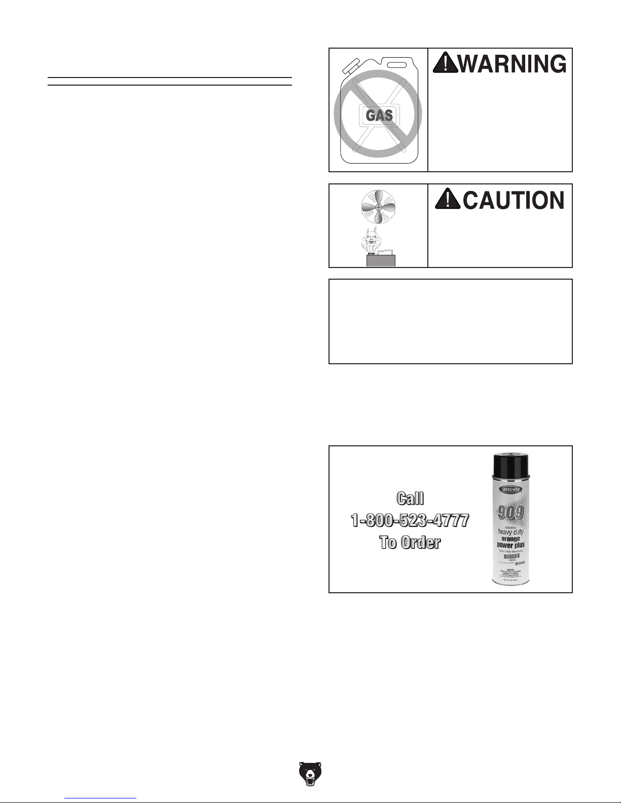
Gasoline and petroleum
products have low flash
points and can explode
or cause fire if used to
clean machinery. Avo id
using these products
to clean machinery.
Put on safety glasses.
Coat the rust preventative with a liberal
amount of cleaner/degreaser, then let it soak
for 5–10 minutes.
Wipe off the surfaces. If your cleaner/degreas-
er is effective, the rust preventative will wipe
off easily. If you have a plastic paint scraper,
scrape off as much as you can first, then wipe
off the rest with the rag.
are toxic if inhaled. Only
area.
NOTICE
Avoid harsh solvents like acetone or brake
parts cleaner that may damage painted surfaces. Always test on a small, inconspicuous location first.
T23692—Orange Power Degreaser
A great product for removing the waxy shipping grease from the non-painted parts of the
machine during clean up.
Repeat Steps 2–3 as necessary until clean,
then coat all unpainted surfaces with a quality
metal protectant to prevent rust.
-16 -
Figure 10. T23692 Orange Power Degreaser.
Model G0845P (Mfd. Since 01/18)
Site Considerations
Weight Load
Refer to the
of your machine. Make sure that the surface upon
which the machine is placed will bear the weight
of the machine, additional equipment that may be
installed on the machine, and the heaviest workpiece that will be used. Additionally, consider the
weight of the operator and any dynamic loading
that may occur when operating the machine.
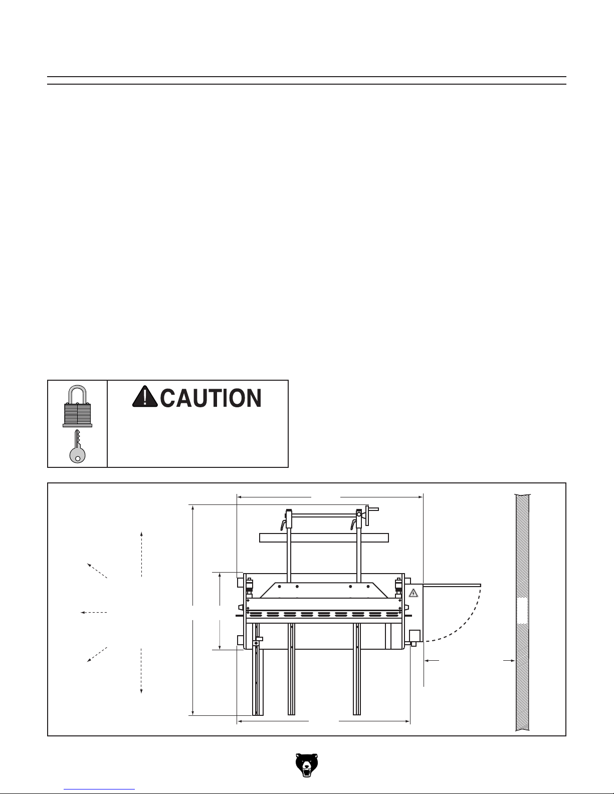
Space Allocation
Consider the largest size of workpiece that will
be processed through this machine and provide
enough space around the machine for adequate
operator material handling or the installation of
auxiliary equipment. With permanent installations,
leave enough space around the machine to open
or remove doors/covers as required by the maintenance and service described in this manual.
See below for required space allocation.
Physical Environment
Extreme conditions for this type of machinery are
Place this machine near an existing power source.
other hazards. Make sure to leave enough space
Shadows, glare, or strobe effects that may distract
Machine Data Sheet for the weight
Children or untrained people
may be seriously injured by
this machine. Only install in an
access restricted location.
The physical environment where the machine is
operated is important for safe operation and longevity of machine components. For best results,
operate this machine in a dry environment that is
free from excessive moisture, hazardous chemicals, airborne abrasives, or extreme conditions.
generally those where the ambient temperature
range exceeds 41°–104°F; the relative humidity
range exceeds 20%–95% (non-condensing); or
the environment is subject to vibration, shocks,
or bumps.
Electrical Installation
Make sure all power cords are protected from
traffic, material handling, moisture, chemicals, or
around machine to disconnect power supply or
apply a lockout/tagout device, if required.
Lighting
Lighting around the machine must be adequate
enough that operations can be performed safely.
or impede the operator must be eliminated.
721/2"
Model G0845P (Mfd. Since 01/18)
Keep
Workpiece
Loading/
Unloading Areas
Unobstructed
281/2"
80"
Figure 11. Minimum working clearances.
Min. 30" for
671/2"
Maintenance
Wall
-17-
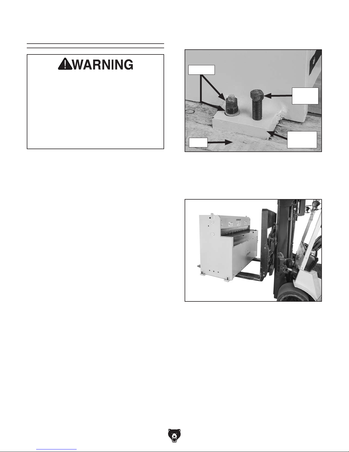
Lifting & Placing
2. Remove (2) hex nuts and (1) flat washer on
each mounting foot (see Figure 12).
This is an extremely heavy machine! Serious
personal injury or death may occur if safe
lifting and moving methods are not followed. To be safe, you will need assistance
and power equipment when moving the
shipping crate and removing the machine
from the crate. Seek assistance from a
professional rigger if you are unsure about
your abilities or maximum load ratings of
your lifting equipment.
DO NOT attempt to lift or move machine without
using proper lifting equipment (such as forklift or
crane) and assistance from other people. Each
piece of lifting equipment must be rated for at
least 4000 lbs. to support dynamic loads that
may be applied while lifting.
Review the Power Supply section beginning on
Page 10, then prepare a permanent location for
the machine.
Remove
Do Not
Remove
Mounting
Pallet
Figure 12. Remove hex nuts and flat washers
securing machine to pallet.
3. Carefully slide forklift forks under machine
base (see Figure 13).
Foot
Note: Place the G0845P on a level concrete floor.
Position the machine to provide clear access for
the loading and unloading areas (refer to Site
Considerations on Page 17).
Items Needed Qty
Forklift (Rated For At Least 4000 lbs.) .............. 1
Wrench or Socket 18mm ................................... 1
Another Person .................................................. 1
To move machine:
1. Remove shipping crate and accessories box.
Figure 13. Lifting the Model G0845P.
4. Lift machine enough to just clear shipping
pallet.
5. Move machine to prepared location.
-18-
Model G0845P (Mfd. Since 01/18)
Lag shield anchors with lag screws (see below)
are a popular way to anchor machinery to a concrete floor, because the anchors sit flush with the
floor surface, making it easy to unbolt and move
the machine later, if needed. However, anytime
local codes apply, you MUST follow the anchoring
methodology specified by the code.
Anchoring machinery to the floor prevents tipping
or shifting and reduces vibration that may occur
during operation, resulting in a machine that runs
slightly quieter and feels more solid.
If the machine will be installed in a commercial or
workplace setting, or if it is permanently connected (hardwired) to the power supply, local codes
may require that it be anchored to the floor.
Leveling
Anchoring to Floor
Leveling the machine helps the blades and other
cast-iron components remain straight and flat during the life of the machine. A machine placed on
an unleveled floor may have components slowly
twist over time due to the dynamic loads placed
on it during operation. Twisted components will
negatively affect the ability of the machine to cut
straight or square.
Items Needed Qty
Open-End Wrench 17mm .................................. 1
Precision Level (at least 12" long) ..................... 1
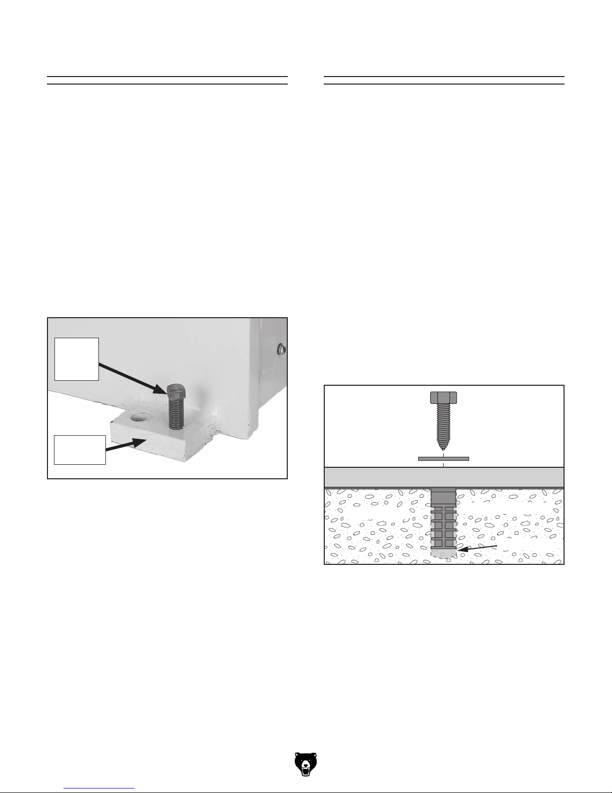
Use the square-head bolt in each mounting foot
to level the machine (see Figure 14). If needed,
place a metal shim under the mounting foot.
Square-
Head
Bolt
Number of Mounting Holes ............................ 4
Diameter of Mounting Hardware .................
5
⁄8"
Anchoring to Concrete Floors
Mounting
Foot
Figure 14. Use square-head bolt to adjust level.
For best results, use a precision level that is at
least 12" long and sensitive enough to show a
distance movement when a 0.003" shim (approximately the thickness of one sheet of standard
newspaper) is placed under one end of the level.
The Model H2683 Master Machinist's Level is one
example available from Grizzly.
Lag Screw
Flat Washer
Machine Base
Concrete
Figure 15. Popular method for anchoring
machinery to a concrete floor.
Lag Shield Anchor
Drilled Hole
Model G0845P (Mfd. Since 01/18)
-19 -
 Loading...