

Grizzly G0841 Owner's Manual

MODEL G0841
18" DOUBLE-SIDED PLANER
w/SPIRAL CUTTERHEADS
OWNER'S MANUAL
(For models manufactured since 06/18)
COPYRIGHT © JULY, 2018 BY GRIZZLY INDUSTRIAL, INC.
WARNING: NO PORTION OF THIS MANUAL MAY BE REPRODUCED IN ANY SHAPE
OR FORM WITHOUT THE WRITTEN APPROVAL OF GRIZZLY INDUSTRIAL, INC.
#ESTK19509 PRINTED IN TA IWAN
V1. 0 7.18

This manual provides critical safety instructions on the proper setup,
operation, maintenance, and service of this machine/tool. Save this
document, refer to it often, and use it to instruct other operators.
Failure to read, understand and follow the instructions in this manual
may result in fire or serious personal injury—including amputation,
electrocution, or death.
The owner of this machine/tool is solely responsible for its safe use.
This responsibility includes but is not limited to proper installation in
a safe environment, personnel training and usage authorization,
proper inspection and maintenance, manual availability and comprehension, application of safety devices, cutting/sanding/grinding tool
integrity, and the usage of personal protective equipment.
The manufacturer will not be held liable for injury or property damage
from negligence, improper training, machine modifications or misuse.
Some dust created by power sanding, sawing, grinding, drilling, and
other construction activities contains chemicals known to the State
of California to cause cancer, birth defects or other reproductive
harm. Some examples of these chemicals are:
• Lead from lead-based paints.
• Crystalline silica from bricks, cement and other masonry products.
• Arsenic and chromium from chemically-treated lumber.
Your risk from these exposures varies, depending on how often you
do this type of work. To reduce your exposure to these chemicals:
Work in a well ventilated area, and work with approved safety equipment, such as those dust masks that are specially designed to filter
out microscopic particles.

Table of Contents
INTRODUCTION ............................................... 2
Contact Info.................................................... 2
Manual Accuracy ........................................... 2
Identification (Front) ....................................... 3
Identification (Rear)........................................ 4
Identification (Right) ....................................... 5
Controls & Components ................................. 6
Internal Components.................................... 10
Machine Data Sheet .................................... 11
SECTION 1: SAFETY ..................................... 14
Safety Instructions for Machinery ................ 14
Additional Safety for Double-Sided Planers 16
SECTION 2: POWER SUPPLY ...................... 17
SECTION 3: SETUP ....................................... 19
Needed for Setup ......................................... 19
Unpacking .................................................... 19
Inventory ...................................................... 20
Cleanup ........................................................ 21
Site Considerations ...................................... 22
Lifting & Placing ........................................... 23
Leveling ........................................................ 24
Assembly ..................................................... 25
Lubricating Machine ..................................... 26
Dust Collection ............................................. 26
Power Connection........................................ 27
Test Run ...................................................... 28
Tightening Belts ........................................... 31
SECTION 5: ACCESSORIES ......................... 45
SECTION 6: MAINTENANCE ......................... 48
Schedule ...................................................... 48
Cleaning & Protecting .................................. 49
Lubrication ................................................... 49
SECTION 7: SERVICE ................................... 56
Troubleshooting ........................................... 56
Tensioning/Replacing V-Belts ...................... 59
Checking/Adjusting Pulley Alignment .......... 62
Aligning Lower Cutterhead Height ............... 64
Calibrating Lower Cutterhead Depth of Cut 66
Setting Upper Cutterhead at BDC ............... 67
Squaring Headstock..................................... 68
Setting Headstock Height ............................ 70
Adjusting Upper Cutterhead Components ... 70
Tensioning Elevation Chain ......................... 77
Tensioning Feed Track ................................ 78
WARRANTY & RETURNS ............................. 81
SECTION 4: OPERATIONS ........................... 32
Operation Overview ..................................... 32
Planing Tips ................................................. 33
Workpiece Inspection................................... 34
Wood Types ................................................. 35
Cutting Problems ......................................... 35
Setting Depth of Cut (Lower Cutterhead) .... 36
Setting Depth of Cut (Upper Cutterhead) .... 37
Adjusting Infeed Safety Guard ..................... 38
Using Digital Controls .................................. 39
Setting Feed Rate ........................................ 41
Adjusting Feed Track Pressure ................... 41
Rotating/Replacing Cutterhead Inserts ........ 42

We stand behind our machines! If you have questions or need help, contact us with the information
below. Before contacting, make sure you get the
serial number
from the
machine ID label. This will help us help you faster.
We want your feedback on this manual. What did
you like about it? Where could it be improved?
Please take a few minutes to give us feedback.
Email: manuals@grizzly.com
We are proud to provide a high-quality owner’s
manual with your new machine!
We
instructions, specifications, drawings, and photographs
in this manual. Sometimes we make mistakes, but
our policy of continuous improvement also means
that
you receive is
slightly different than shown in the manual
If you find this to be the case, and the difference
between the manual and machine leaves you
confused or unsure about something
check our
website for an updated version. W
current
manuals and
on our web-
site at
Alternatively, you can call our Technical Support
for help. Before calling, make sure you write down
the
from
the machine ID label (see below). This information
is required for us to provide proper tech support,
and it helps us determine if updated documentation is available for your machine.
INTRODUCTION
Contact Info
and manufacture date
Grizzly Technical Support
1815 W. Battlefield
Springfield, MO 65807
Phone: (570) 546-9663
Email: techsupport@grizzly.com
Grizzly Documentation Manager
P.O. Box 2069
Bellingham, WA 98227-2069
Manual Accuracy
made every effort to be exact with the
sometimes the machine
.
,
e post
manual updates for free
www.grizzly.com.
Manufacture Date and Serial Number
Manufacture Date
Serial Number
-2-
Model G0841 (Mfd. Since 06/18)
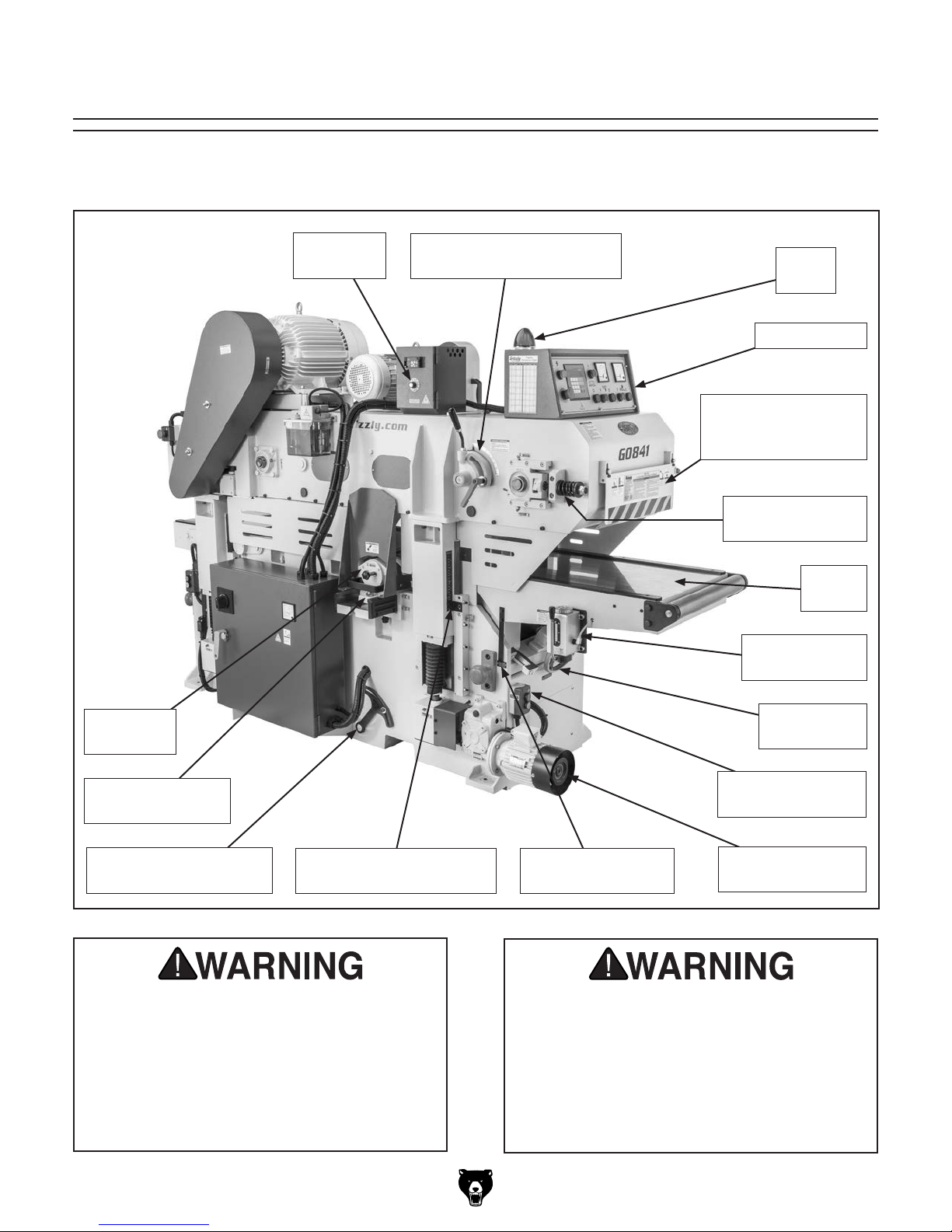
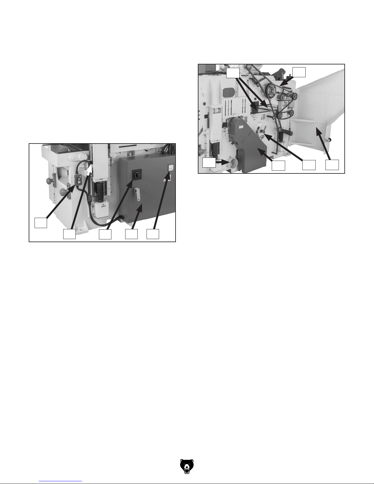
Identification (Front)
Become familiar with the names and locations of the controls and features shown below to better understand
the instructions in this manual.
Feed Rate
Dial
Feed Track Tension Lever
w/Scale & Lock Lever
Power
Lamp
Control Panel
Infeed Safety Guard
w/Emergency Stop
Plate
Feed Track
Tensioner (1 of 2)
Infeed
Table
One-Shot Oiler
w/Reservoir
Lower
Cutterhead
Lower Cutterhead
Carriage
Headstock Elevation
Chain Tensioner
Like all machinery there is potential danger
when operating this machine. Accidents
are frequently caused by lack of familiarity
or failure to pay attention. Use this machine
with respect and caution to decrease the
risk of operator injury. If normal safety precautions are overlooked or ignored, serious personal injury may occur.
Upper Cutterhead Depth-
of-Cut Scale (1 of 2)
Infeed Table
Handwheel
Headstock Height
Switch (1 of 2)
Lower Cutterhead
Depth-of-Cut Scale
No list of safety guidelines can be complete. Every shop environment is different.
Always consider safety first, as it applies
to your individual working conditions. Use
this and other machinery with caution and
respect. Failure to do so could result in
serious personal injury, damage to equipment, or poor work results.
Headstock Height
Handwheel
Model G0841 (Mfd. Since 06/18)
-3-
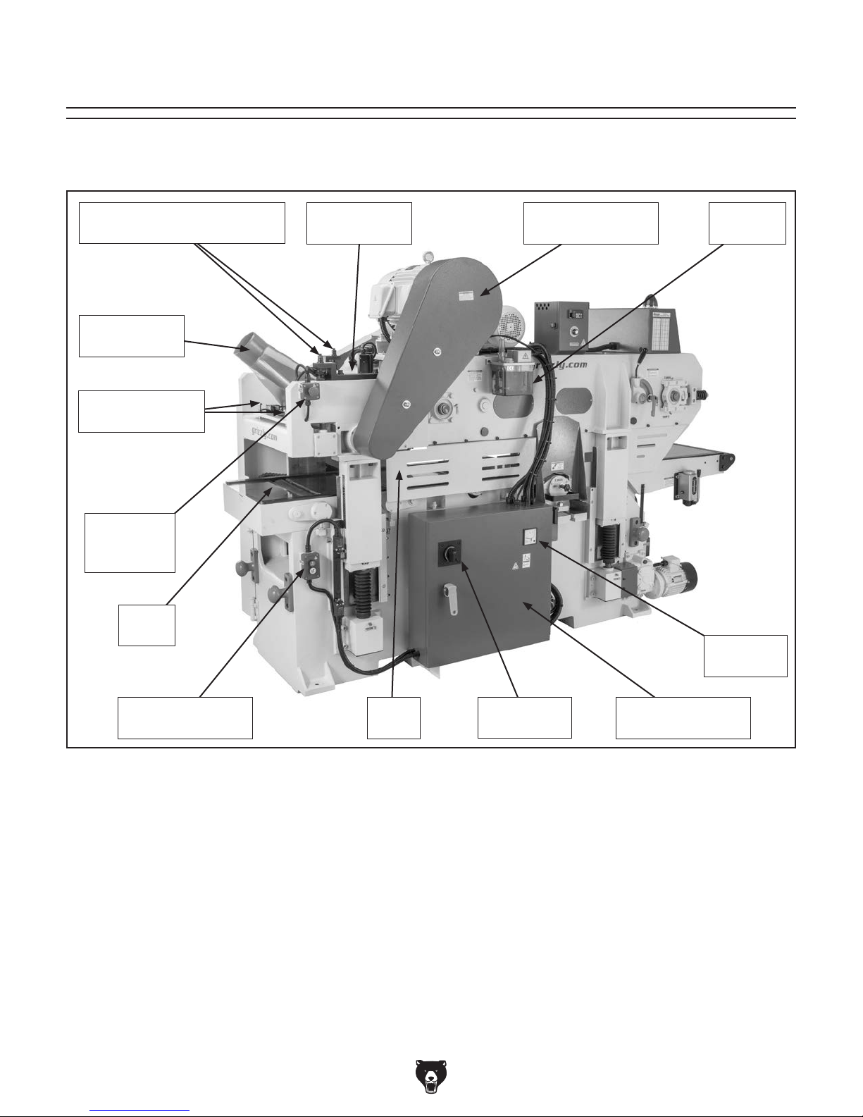
Identification (Rear)
Become familiar with the names and locations of the controls and features shown below to better understand
the instructions in this manual.
Adjustment Rods for
Serrated & Pressure Rollers
Dust Hood w/
5" Dust Port
Pressure Bar
Adjustment Bolts
Emergency
Stop Button
(1 of 2)
Planer
Table
Chip Breaker
Access Cover
Upper Cutterhead
Belt Cover
Automatic
Oiler
Machine
Amp Meter
Headstock Height
Switch (1 of 2)
-4-
Table
Guard
Main Power
Switch
Electrical Panel w/
Lock-Out Handle
Model G0841 (Mfd. Since 06/18)

Identification (Right)
Become familiar with the names and locations of the controls and features shown below to better understand
the instructions in this manual.
Automatic Oiler
Switch
Chain
Drive
Serrated
Roller
Upper
Cutterhead
Upper
Pressure
Roller
Chain Drive
Access Door
Lower
Pressure
Rollers
6" Dust
Port
Lower Cutterhead Belt
Tension Lever w/Lock Lever
Lower Cutterhead
Belt Cover
Model G0841 (Mfd. Since 06/18)
-5-

Controls &
To reduce your risk of
serious injury, read this
entire manual BEFORE
Components
using machine.
F. Upper Cutterhead Off Button: Push to stop
upper cutterhead motor. (Upper cutterhead
requires 30–40 seconds to come to complete
stop.)
G. Upper Cutterhead On Button: Push to start
upper cutterhead motor. (Upper cutterhead
requires 5–15 seconds to reach full speed.)
H. Lower Cutterhead Off Button: Push to stop
lower cutterhead motor. (Upper cutterhead
requires 30–40 seconds to come to complete
stop.)
Refer to Figures 1–7 and the following descriptions to become familiar with the basic controls
and components of this machine. Understanding
these items and how they work will help you
understand the rest of the manual and how to
properly operate this machine.
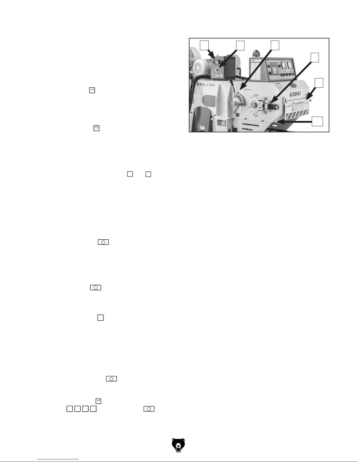
Control Panel
B
C D E
A
L K
J
I
Figure 1. Control panel.
GH
F
I. Lower Cutterhead On Button: Push to start
lower cutterhead motor. (Lower cutterhead
requires 5–15 seconds to reach full speed.)
J. Feed System Off Button: Push to stop feed
system.
K. Feed System On Button: Push to start feed
system, including: feed track, serrated roller,
pressure rollers, and chain drive. Button only
functions when cutterheads reach full speed.
L. Emergency Stop Button (1 of 2): Push to
stop all machine functions and disable power
button. Remains in depressed position until
manually reset. Reset by twisting button
clockwise until it springs outward.
Digital Control Pad
N
O
A. Power Button: Push to enable power to all
motors and electrical systems (if Emergency
Stop buttons are not in depressed position).
B. Power Lamp: Illuminates when machine is
connected to power.
C. Lower Cutterhead Motor Amp Meter:
Displays lower cutterhead motor amp draw.
D. Upper Cutterhead Motor Amp Meter:
Displays upper cutterhead motor amp draw.
E. Automatic Oiler On/Off Switch: Use to turn
automatic oiler system on and off. Always
turn ON before starting feed system.
-6-
M
U
T
Figure 2. Digital control pad.
Note: You use the digital control pad to enter a
value for your final workpiece thickness (i.e., distance from bottom dead center (BDC) of upper
cutterhead to planer table).
Model G0841 (Mfd. Since 06/18)
P
Q
R
S
M. Digital Display: Displays current final
+
workpiece thickness (i.e., distance from BDC
of upper cutterhead to planer table).
Headstock (Front)
V
W
X
N. Unit/Mode Display: Identifies active unit
of measurement (INCH or MM) and mode
(INPUT or RUN) of digital contol pad.
SET
O. SET Key: Press
key to enter Input mode.
INPUT is highlighted in the unit/mode display
(see Figure 2). Input mode must be active to
enter a final workpiece thickness value.
UNIT
P. UNIT Key: Press
key to switch between
inches or millimeters as unit of measurement for digital control pad. The selected
unit (INCH or MM) is highlighted in unit/mode
display (see Figure 2).
Q. Plus & Minus Keys: Press
or − keys
to quickly raise or lower the headstock,
which increases or decreases final workpiece
thickness (i.e., distance from BDC of upper
cutterhead to planer table). Push and hold
buttons to raise or lower headstock steadily,
or push and release buttons to raise or lower
headstock in 0.01" or 0.1mm increments.
R. Start Key: Press
key to enter Run
mode. The headstock will move up or down,
depending on the entered final workpiece
thickness (i.e., distance from BDC of upper
cutterhead to planer table).
i
S. Stop Key: Press
key while in Run mode
to immediately stop headstock while it is
moving.
C
T. Clear Key: Press
key to clear current
final workpiece thickness value while in Input
mode.
U. Numerical Key Pad: Enter specific values
for final workpiece thickness. Press 0–9 and
decimal keys as needed to enter desired final
workpiece thickness. The displayed value
flashes until you press
key.
Example: To enter a final workpiece thick-
ness of 2
ing keys:
1
⁄2", press
2
• 5 0, and then press key.
SET
key, then press follow-
Y
Z
AA
Figure 3. Headstock (front) controls &
components.
V. Variable Frequency Drive (VFD) Control
Module: Set at factory. DO NOT adjust!
W. Feed Rate Dial: Turn to set machine feed
rate between 0–100% (26–72 FPM). Feed
rate is the speed in Feet Per Minute (FPM)
that the feed system moves workpieces
through the machine.
X. Feed Track Pressure Adjustment w/Scale
& Lock Lever: Adjust to increase or decrease
feed track pressure on workpiece. Set pressure to "0" for normal planing operations; if
belt slips on workpiece, increase downward
pressure by no more than 0.5mm at a time.
Y. Feed Track Tensioner (1 of 2): Tighten or
loosen spring-loaded hex bolt to increase or
decrease tension on the feed track.
Z. Infeed Safety Guard w/Emergency Stop
Plate: Provides additional safety for operator
when feeding workpieces into machine. Guard
is adjustable for varying pre-cut workpiece
thicknesses. If contact is made with emergency stop plate, cutterhead motors and feed
system immediately stop.
AA. Feed Track: Feeds workpieces into lower
cutterhead and toward serrated roller (refer
to Feed Track on Page 10 for more information).
Model G0841 (Mfd. Since 06/18)
-7-
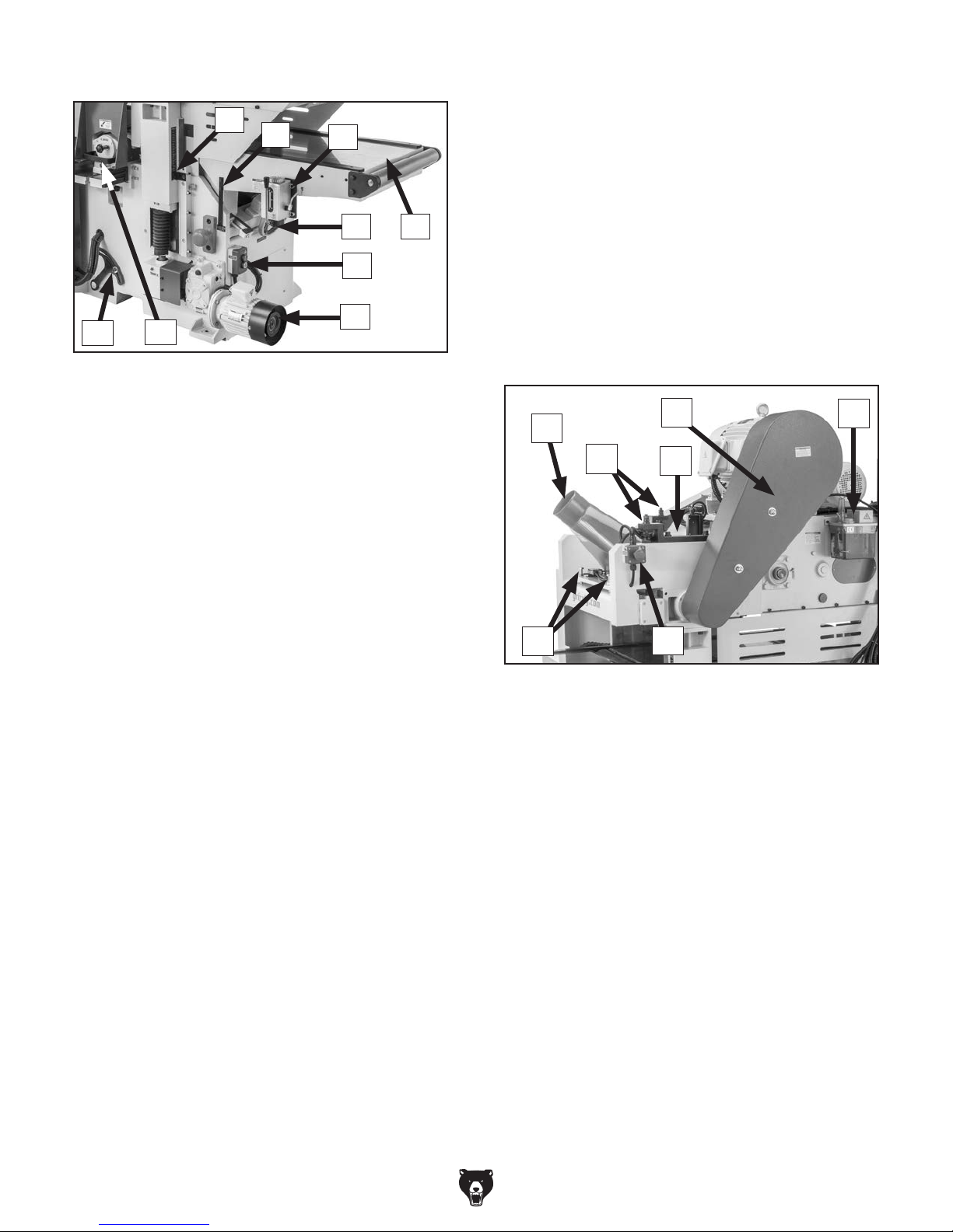
Base (Front)
AJ
AI
AB
AC
AD
AF
AG
AH
AE
AH. Headstock Height Handwheel: Rotate
handwheel clockwise or counterclockwise
to precisely raise or lower the headstock in
0.1mm (0.004 in.) increments. Handwheel is
located at back of elevation motor.
AI. Lower Cutterhead Carriage w/Handle:
Provides access to lower cutterhead for
service/maintenance.
AJ. Elevation Chain Tensioner: Adjust to
increase or decrease tension on the elevation chain.
Figure 4. Base (front) controls & components.
AB. Upper Cutterhead Depth-of-Cut Scale
(1 of 2): Indicates final workpiece thickness
(i.e., distance from BDC of upper cutterhead
to planer table) in inches and millimeters.
AC. Lower Cutterhead Depth-of-Cut Scale:
Indicates amount of material to be removed
from bottom of workpiece (i.e., table offset) in
millimeters.
AD. One-Shot Oiler w/Reservoir: Pull lever
down to dispense oil onto infeed table surface. Oiling table surface reduces friction
between workpieces and table surface. Use
oiler sparingly to avoid saturating workpieces.
AE. Infeed Table: Provides a smooth and
level surface to feed workpieces into lower
cutterhead (refer to Infeed Table on Page 10
for more information).
AF. Infeed Table Handwheel: Rotate to raise or
lower infeed table (refer to Infeed Table on
Page 10 for more information).
AG. Headstock Height Switch (1 of 2): Push UP
or DOWN buttons to quickly raise or lower
the headstock. Sets final workpiece thickness
(i.e., distance from BDC of upper cutterhead
to planer table).
Headstock (Rear)
AM
AN
AL
Figure 5. Headstock (rear) controls &
AK. Emergency Stop Button (1 of 2): Push to
stop all machine functions and disable power
button. Remains in depressed position until
manually reset. Reset by twisting button
clockwise until it springs outward.
AL. Pressure Bar Adjustment Bolts: Adjust
bolts to set pressure bar height. Jam nuts
lock adjustment bolts in position.
AM. Dust Hood w/5" Dust Port: Covers upper
cutterhead to extract wood particles.
5" dust port provides connection to dustcollection system. Remove hood to access
upper cutterhead, pressure bar, and pressure
rollers for service/maintenance.
AP
AO
AK
components.
AQ
-8-
AN. Serrated & Upper Pressure Roller
Adjustment Rods (2 of 4): Adjust rods to
set serrated and upper pressure roller height.
Jam nuts lock adjustment rods in position.
Model G0841 (Mfd. Since 06/18)
AO. Chipbreaker Access Cover: Remove cover
to access chipbreaker segments for service/
maintenance.
AP. Upper Cutterhead Belt Guard: Protects
operator from spinning upper cutterhead
belts and pulleys during operation. Remove
cover to access belts and pulleys for service/
maintenance.
AQ. Automatic Oiler w/Reservoir: Slowly oils
feed track gear and chain.
Base (Rear)
AV. Machine Amp Meter: Displays total machine
amperage draw.
Machine (Right)
AW
AX
AR
AS
Figure 6. Base (rear) controls & components.
AR. Headstock Height Switch (1 of 2): Push UP
or DOWN buttons to quickly raise or lower
the headstock. Sets final workpiece thickness
(i.e., distance from BDC of upper cutterhead
to planer table).
AS. Upper Cutterhead Depth-of-Cut Scale
(1 of 2): Indicates final workpiece thick-
ness (i.e., distance from BDC of upper
cutterhead to planer table) in inches and
millimeters.
AT. Main Power Switch w/Integrated Lock-
out: Trips when amperage draw exceeds
set threshold. Turn switch to reset tripped
breaker. Switch has lock-out feature to disable machine start up.
AT
AVAU
BB
Figure 7. Machine (right) controls &
components.
AW. Planer Table: Provides a smooth and
level surface to feed workpieces into upper
cutterhead (refer to Planer Table on Page 10
for more information).
AX. Chain Drive: Transfers power to feed track,
serrated roller, and pressure rollers.
AY. Chain Drive Access Door: Protects
operator from moving gears and chain during operation. Open door to access upper
cutterhead, serrated roller, pressure rollers,
and drive chain for service/maintenance.
AZ. Lower Cutterhead Belt Tensioner w/Lock
Knob: Adjust to increase or decrease belt
tension on lower cutterhead.
BA. Lower Cutterhead Belt Cover: Protects
operator from spinning belts and pulleys during operation. Open cover to access lower
cutterhead for service/maintenance; remove
cover to access belts and pulleys for service/
maintenance.
BA
AZ
AY
AU. Electrical Panel w/Lock-out Handle:
Provides access to machine wiring for initial
setup. Lock-out handle is easily removable to
prevent unauthorized access.
Model G0841 (Mfd. Since 06/18)
BB. 6" Dust Port: Provides connection to dust-
collection system.
-9-
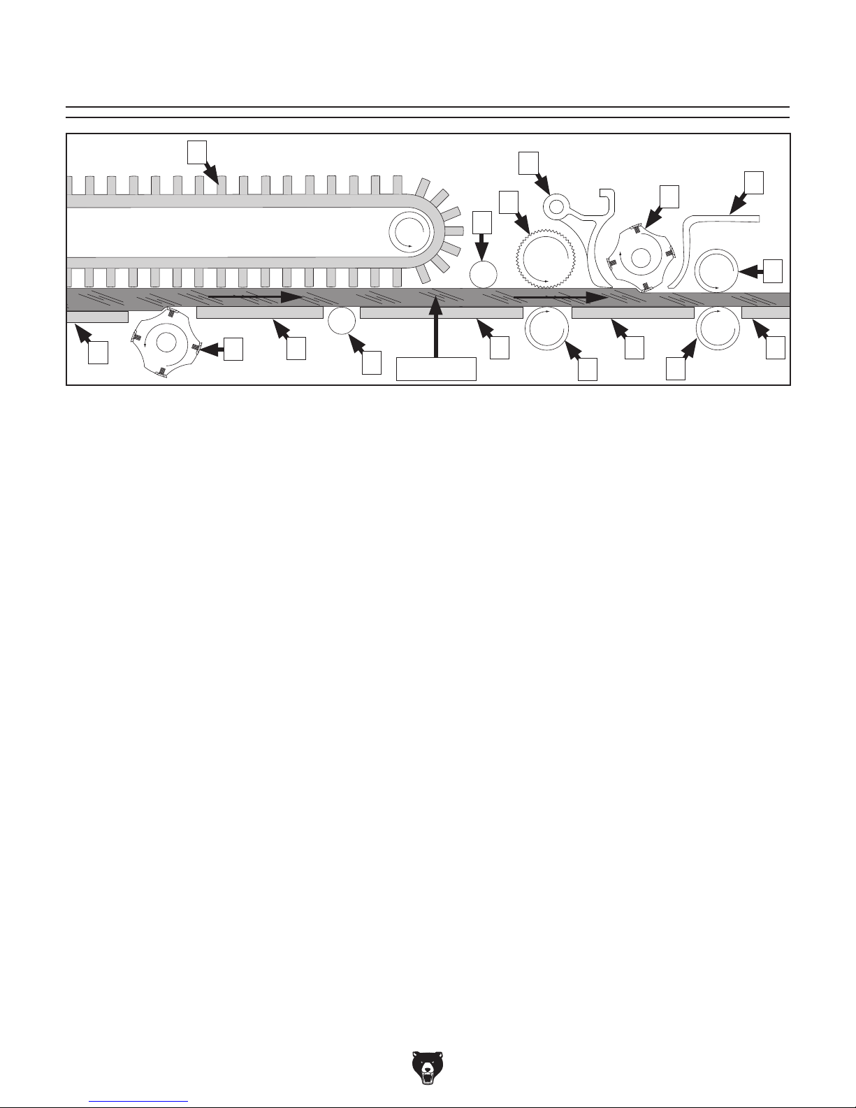
Internal Components
A
B
A. Feed Track: Chain-driven conveyor track that
securely grabs, holds, and feeds workpieces
into the lower cutterhead and toward the
upper cutterhead. Feed track has springloaded fingers to grip workpieces.
B. Infeed Table: Provides a smooth and level
path for workpieces as they are fed into the
lower cutterhead. Table height is adjustable.
Infeed table can be set 0–15mm (0.0"–0.60")
lower than planer table (D), depending on
how much material needs to be removed
from bottom of the workpieces.
C. Lower Cutterhead: Belt-driven cutterhead
that holds 114 indexable carbide inserts
in a longitudinal spiral pattern. Spins at
4000 RPM to remove material from bottom of
the workpieces.
D. Planer Table: Provides a smooth and level
path for workpieces as they are fed into and
through the upper cutterhead. Table height is
not adjustable.
E. Table Roller: Provides a rolling surface
to help feed workpieces toward the upper
cutterhead.
F. Idler Roller: Spring-loaded idler roller that
holds workpieces down as they are fed
toward serrated roller.
C
Figure 8. Major planing components (side cutaway view).
D
E
Workpiece
G. Serrated Roller: Chain-driven roller that
H. Chip Breaker: Breaks off chips created by
I. Lower Pressure Roller: Chain-driven
J. Upper Cutterhead: Belt-driven cutterhead
K. Pressure Bar: Stabilizes workpieces as they
L. Upper Pressure Roller: Chain-driven roll-
M. Lower Pressure Roller: Chain-driven roll-
H
K
G
F
D
I
grabs and pulls workpieces into the upper
cutterhead.
the upper cutterhead to reduce tearout and
assists in deflecting wood particles toward
the dust hood.
roller that pulls workpieces into the upper
cutterhead.
that holds 114 indexable carbide inserts
in a longitudinal spiral pattern. Spins at
4000 RPM to remove material from top of the
workpiece.
leave the upper cutterhead and assists in
deflecting wood particles toward the dust
hood.
er that pulls workpieces through the upper
cutterhead.
er that pulls workpieces through the upper
cutterhead.
J
L
D
M
D
-10 -
Model G0841 (Mfd. Since 06/18)

Belt Drive
Belt Drive
Machine Data Sheet
Customer Service #: (570) 546-9663 · To Order Call: (800) 523-4777 · Fax #: (800) 438-5901
MODEL G0841
18" DOUBLE-SIDED PLANER w/SPIRAL CUTTERHEADS
Product Dimensions:
Weight ......................................................................................................................................................................... 5512 lbs.
Width (side-to-side) x Depth (front-to-back) x Height .....................................................................................39 x 106 x 67 in.
Footprint (Length/Width) ......................................................................................................................................74-1/2 x 27 in.
Shipping Dimensions:
Type ........................................................................................................................................................................ Wood Crate
Content .......................................................................................................................................................................... Machine
Weight .......................................................................................................................................................................... 6614 lbs.
Length x Width x Height ................................................................................................................................... 110 x 47 x 70 in.
Must Ship Upright .................................................................................................................................................................Yes
Electrical:
Power Requirement ................................................................................................................................ 240V, 3-Phase, 60 Hz
Full-Load Current Rating ................................................................................................................................................... 69.2A
Minimum Circuit Size ......................................................................................................................................................... 100A
Connection Type ....................................................................................................... Permanent (Hardwired to Shutoff Switch)
Switch Type .............................................................................................................................Magnetic w/Overload Protection
Motor:
Upper Cutterhead
Horsepower .............................................................................................................................................................15 HP
Phase .................................................................................................................................................................. 3-Phase
Amps ....................................................................................................................................................................... 38.5A
Speed ...............................................................................................................................................................1760 RPM
Type ..........................................................................................................................................................TEFC Induction
Power Transfer ..................................................................................................................................................
Bearings ......................................................................................................................Sealed & Permanently Lubricated
Lower Cutterhead
Horsepower .............................................................................................................................................................10 HP
Phase .................................................................................................................................................................. 3-Phase
Amps .......................................................................................................................................................................... 23A
Speed ...............................................................................................................................................................1760 RPM
Type ..........................................................................................................................................................TEFC Induction
Power Transfer ..................................................................................................................................................
Bearings ......................................................................................................................Sealed & Permanently Lubricated
Model G0841 (Mfd. Since 06/18)
-11-

Feed System
Horsepower ...............................................................................................................................................................2 HP
Phase .................................................................................................................................................................. 3-Phase
Amps ......................................................................................................................................................................... 6.1A
Speed ...............................................................................................................................................................1720 RPM
Type ..........................................................................................................................................................TEFC Induction
Power Transfer .................................................................................................................................................... Gearbox
Bearings ......................................................................................................................Sealed & Permanently Lubricated
Feed System Power Inverter (VFD)
Type .................................................................................................................... Fuji Electric Frenic-Ace FRN2.2E2S-2J
Power Requirement .......................................................................................................... 200–240V, 3-Phase, 50/60 Hz
Headstock Elevation
Horsepower ............................................................................................................................................................1/2 HP
Phase .................................................................................................................................................................. 3-Phase
Amps ......................................................................................................................................................................... 1.6A
Speed ...............................................................................................................................................................1700 RPM
Type ..........................................................................................................................................................TEFC Induction
Power Transfer .................................................................................................................................................... Gearbox
Bearings ......................................................................................................................Sealed & Permanently Lubricated
Main Specifications:
Operation Information
Planer Table Size .....................................................................................................................................................18 in.
Max. Cut Width ......................................................................................................................................................... 18 in.
Max. Stock Thickness ................................................................................................................................................8 in.
Max. Cut Height ....................................................................................................................................................7-3/4 in.
Min. Stock Length ..................................................................................................................................................... 12 in.
Min. Stock Width ..................................................................................................................................................2-1/2 in.
Min. Stock Thickness ..............................................................................................................................................1/2 in.
Number of Cuts Per Inch ........................................................................................................................... 77–28 Cuts/in.
Number of Cuts Per Minute ................................................................................................................... 24,000 (effective)
Cutterhead Speed ............................................................................................................................................4000 RPM
Planing Feed Rate .......................................................................................................................................... 26–72 FPM
Max. Cut Depth Upper Cutterhead Full Width ......................................................................................................3/16 in.
Max. Cut Depth Upper Cutterhead 6-Inch Wide Board ........................................................................................5/16 in.
Max. Cut Depth Lower Cutterhead Full Width ......................................................................................................3/16 in.
Max. Cut Depth Lower Cutterhead 6-Inch Wide Board ........................................................................................5/16 in.
Cutterhead Information (Upper)
Cutterhead Type .......................................................................................................................................................Spiral
Cutterhead Diameter ............................................................................................................................................5-1/8 in.
Number of Cutter Rows ...................................................................................................................................................6
Number of Indexable Cutters ......................................................................................................................................114
Cutter Insert Type ................................................................................................................................ Indexable Carbide
Cutter Insert Size Length .......................................................................................................................................15 mm
Cutter Insert Size Width .........................................................................................................................................15 mm
Cutter Insert Size Thickness .................................................................................................................................2.5 mm
Cutterhead Information (Lower)
Cutterhead Type .......................................................................................................................................................Spiral
Cutterhead Diameter ............................................................................................................................................5-1/8 in.
Number of Cutter Rows ...................................................................................................................................................6
Number of Indexable Cutters ......................................................................................................................................114
Cutter Insert Type ................................................................................................................................ Indexable Carbide
Cutter Insert Size Length .......................................................................................................................................15 mm
Cutter Insert Size Width .........................................................................................................................................15 mm
Cutter Insert Size Thickness .................................................................................................................................2.5 mm
-12-
Model G0841 (Mfd. Since 06/18)

Table Information
Table Bed Size Length ...........................................................................................................................................102 in.
Table Bed Size Width ............................................................................................................................................... 18 in.
Table Bed Size Thickness ....................................................................................................................................2-1/2 in.
Floor-to-Table Height ............................................................................................................................ 31-1/2–39-1/2 in.
Construction
Table .......................................................................................................................................... Ground & Polished Steel
Body ...................................................................................................................................................................Cast Iron
Cutterhead Assembly ................................................................................................................................................Steel
Infeed Roller ..............................................................................................................................................................Steel
Outfeed Roller ...........................................................................................................................................................Steel
Paint Type/Finish ................................................................................................................................................ Urethane
Other
Measurement Scale .....................................................................................................................................Inch & Metric
Number of Dust Ports ......................................................................................................................................................2
Dust Port Size ..................................................................................................................................................... 5 & 6 in.
Other Specifications:
Country of Origin ............................................................................................................................................................. Taiwan
Warranty ........................................................................................................................................................................... 1 Year
Approximate Assembly & Setup Time .............................................................................................................................1 Hour
Serial Number Location ................................................................................................................................................ ID Label
ISO 9001 Factory ................................................................................................................................................................... No
Certified by a Nationally Recognized Testing Laboratory (NRTL) ......................................................................................... No
Features:
Dual Spiral Cutterheads with 114 Indexable Cutters/each
Variable Feed Speed from 26–72 FPM
Feed Belt with Spring-Loaded Fingers
Automatic Oiler for Easy Feed System Lubrication
One-Shot Table Oiler
Programmable Height Adjustment with DRO
5" & 6" Dust Ports
Maximum 8" Workpiece Thickness Capacity
3/8" Maximum Cutting Depth (Full Width)
Emergency Stop Button on Outfeed End of Table
Included Accessories:
Toolbox
Adjustable Wrench 10"
1/4" Ratchet Drive w/T-20 Torx Bits (5)
Pneumatic Screwdriver w/Hose Adapter and Phillips Bits (2)
Open-Ended Wrenches: 19/21mm, 12/14mm
Hex Wrench Set: 1.5, 2, 2.5, 3, 4. 5, 5.5, 6, 8, 10mm
T-Handle Hex Wrench 4mm
Replacement Carbide Inserts 15 x15 x 2.5mm (10)
Torx Head Screws M6-1 x 12 (20)
Block Gauge
Model G0841 (Mfd. Since 06/18)
-13-

SECTION 1: SAFETY
For Your Own Safety, Read Instruction
Manual Before Operating This Machine
The purpose of safety symbols is to attract your attention to possible hazardous conditions.
This manual uses a series of symbols and signal words intended to convey the level of importance of the safety messages. The progression of symbols is described below. Remember that
safety messages by themselves do not eliminate danger and are not a substitute for proper
accident prevention measures. Always use common sense and good judgment.
Indicates an imminently hazardous situation which, if not avoided,
WILL result in death or serious injury.
Indicates a potentially hazardous situation which, if not avoided,
COULD result in death or serious injury.
Indicates a potentially hazardous situation which, if not avoided,
MAY result in minor or moderate injury. It may also be used to alert
against unsafe practices.
This symbol is used to alert the user to useful information about
NOTICE
proper operation of the machine.
Safety Instructions for Machinery
OWNER’S MANUAL. Read and understand this
owner’s manual BEFORE using machine.
TRAINED OPERATORS ONLY. Untrained operators have a higher risk of being hurt or killed.
Only allow trained/supervised people to use this
machine. When machine is not being used, disconnect power, remove switch keys, or lock-out
machine to prevent unauthorized use—especially
around children. Make your workshop kid proof!
DANGEROUS ENVIRONMENTS. Do not use
machinery in areas that are wet, cluttered, or have
poor lighting. Operating machinery in these areas
greatly increases the risk of accidents and injury.
MENTAL ALERTNESS REQUIRED. Full mental
alertness is required for safe operation of machinery. Never operate under the influence of drugs or
alcohol, when tired, or when distracted.
ELECTRICAL EQUIPMENT INJURY RISKS. You
can be shocked, burned, or killed by touching live
electrical components or improperly grounded
machinery. To reduce this risk, only allow qualified
service personnel to do electrical installation or
repair work, and always disconnect power before
accessing or exposing electrical equipment.
DISCONNECT POWER FIRST.
nect machine from power supply BEFORE making
adjustments, changing tooling, or servicing machine.
This prevents an injury risk from unintended startup
or contact with live electrical components.
EYE PROTECTION. Always wear ANSI-approved
safety glasses or a face shield when operating or
observing machinery to reduce the risk of eye
injury or blindness from flying particles. Everyday
eyeglasses are NOT approved safety glasses.
Always discon-
-14-
Model G0841 (Mfd. Since 06/18)

WEARING PROPER APPAREL. Do not wear
clothing, apparel or jewelry that can become
entangled in moving parts. Always tie back or
cover long hair. Wear non-slip footwear to reduce
risk of slipping and losing control or accidentally
contacting cutting tool or moving parts.
HAZARDOUS DUST. Dust created by machinery
operations may cause cancer, birth defects, or
long-term respiratory damage. Be aware of dust
hazards associated with each workpiece material. Always wear a NIOSH-approved respirator to
reduce your risk.
HEARING PROTECTION. Always wear hearing protection when operating or observing loud
machinery. Extended exposure to this noise
without hearing protection can cause permanent
hearing loss.
REMOVE ADJUSTING TOOLS. Tools left on
machinery can become dangerous projectiles
upon startup. Never leave chuck keys, wrenches,
or any other tools on machine. Always verify
removal before starting!
USE CORRECT TOOL FOR THE JOB. Only use
this tool for its intended purpose—do not force
it or an attachment to do a job for which it was
not designed. Never make unapproved modifications—modifying tool or using it differently than
intended may result in malfunction or mechanical
failure that can lead to personal injury or death!
AWKWARD POSITIONS. Keep proper footing
and balance at all times when operating machine.
Do not overreach! Avoid awkward hand positions
that make workpiece control difficult or increase
the risk of accidental injury.
CHILDREN & BYSTANDERS. Keep children and
bystanders at a safe distance from the work area.
Stop using machine if they become a distraction.
GUARDS & COVERS. Guards and covers reduce
accidental contact with moving parts or flying
debris. Make sure they are properly installed,
undamaged, and working correctly BEFORE
operating machine.
FORCING MACHINERY. Do not force machine.
It will do the job safer and better at the rate for
which it was designed.
NEVER STAND ON MACHINE. Serious injury
may occur if machine is tipped or if the cutting
tool is unintentionally contacted.
STABLE MACHINE. Unexpected movement during operation greatly increases risk of injury or
loss of control. Before starting, verify machine is
stable and mobile base (if used) is locked.
USE RECOMMENDED ACCESSORIES. Consult
this owner’s manual or the manufacturer for recommended accessories. Using improper accessories will increase the risk of serious injury.
UNATTENDED OPERATION. To reduce the
risk of accidental injury, turn machine OFF and
ensure all moving parts completely stop before
walking away. Never leave machine running
while unattended.
MAINTAIN WITH CARE. Follow all maintenance
instructions and lubrication schedules to keep
machine in good working condition. A machine
that is improperly maintained could malfunction,
leading to serious personal injury or death.
DAMAGED PARTS. Regularly inspect machine
for damaged, loose, or mis-adjusted parts—or
any condition that could affect safe operation.
Immediately repair/replace BEFORE operating
machine. For your own safety, DO NOT operate
machine with damaged parts!
MAINTAIN POWER CORDS. When disconnecting cord-connected machines from power, grab
and pull the plug—NOT the cord. Pulling the cord
may damage the wires inside. Do not handle
cord/plug with wet hands. Avoid cord damage by
keeping it away from heated surfaces, high traffic
areas, harsh chemicals, and wet/damp locations.
EXPERIENCING DIFFICULTIES. If at any time
you experience difficulties performing the intended operation, stop using the machine! Contact our
Technical Support at (570) 546-9663.
Model G0841 (Mfd. Since 06/18)
-15-

Additional Safety for Double-Sided Planers
To reduce risk of kick-
Amputation, serious cuts, entanglement, or death can occur from contact with rotating
cutterheads, feed track, or other moving parts! Flying chips can cause blindness or eye injuries.
Inserts or workpieces thrown by cutterheads can strike nearby operator or bystanders with
deadly force. To reduce the risk of these hazards, operator and bystanders MUST completely
heed hazards and warnings below.
AVOID CONTACT WITH FEED TRACK. The feed
track grabs, holds, and pulls material with great
force into spinning cutterheads. To reduce risk
of being pulled into machine and spinning cutterheads, keep hands, loose clothing, jewelry, and
long hair away from feed track during operation.
FEED WORKPIECES PROPERLY. To reduce
risk of contacting feed track and being pulled into
machine, stand at arms-length away from infeed
table when feeding workpieces into machine. To
reduce risk of kickback and jams, only feed workpieces into machine when feed system is ON, and
DO NOT change feed rate speed during cutting
operation.
CLEARING JAMMED WORKPIECES. Feeding
too much material into machine at one time
or improper feed techniques will likely cause
workpieces to become jammed. If workpieces
get jammed in machine, turn machine OFF and
disconnect power before clearing jam. NEVER
reach inside machine or use a piece of wood to
clear a jam during operation or while machine is
connected to power. Otherwise, you could be seriously injured if you accidentally touch the spinning
cutterheads or get entangled in moving parts.
KICKBACK. Kickback occurs when workpieces
are ejected from the machine at a high rate of
speed. To reduce risk of kickback and serious
impact injuries, only use proper workpieces and
feed techniques, and NEVER start cutterhead
motors with workpieces touching cutterheads.
CUTTING LIMITATIONS. To reduce risk of kickback and jams, DO NOT exceed maximum depth
of cut or minimum board size dimensions found
in Machine Data Sheet. DO NOT cut multiple
boards of thicknesses varying more than
by-side at same time.
3
⁄16" side-
INSPECTING STOCK.
back, jams, and machine damage, thoroughly
inspect and prepare stock before cutting. Verify
workpieces are free of nails, staples, loose knots,
debris, and foreign objects.
PLANING CORRECT MATERIAL. Only plane
natural wood stock with this machine. DO NOT
plane MDF, OSB, plywood, laminates or other
synthetic materials that can break up inside
machine and be ejected towards operator or
bystanders.
AVOID CONTACT WITH MOVING PARTS.
NEVER reach inside planer or open chain drive
access door or belt covers during operation or
while machine is connected to power. Serious
injury or death can occur if you contact cutterhead
or get entangled in moving chain drive or belts.
LOOKING INSIDE MACHINE. Wood chips fly
around inside machine at a high rate of speed
during operation. To avoid injury from flying
wood chips, DO NOT look inside planer during
operation.
SECURE INSERTS. Improperly secured inserts
can break apart or come loose and become
dangerous projectiles. Always verify inserts are
secure and properly adjusted before operation.
DULL/DAMAGED INSERTS. Dull or damaged
inserts increase risk of kickback and jams and
cause poor workpiece finish. Only use sharp,
undamaged inserts.
WORKPIECE SUPPORT. To reduce risk of kickback and jams, always make sure workpieces can
move completely across tables without rocking
or tipping. For long stock, use auxiliary support
stands on infeed and outfeed ends of machine.
-16 -
Model G0841 (Mfd. Since 06/18)

Before installing the machine, consider the availability and proximity of the required power supply
circuit. If an existing circuit does not meet the
requirements for this machine, a new circuit must
be installed. To minimize the risk of electrocution,
fire, or equipment damage, installation work and
electrical wiring must be done by an electrician or
qualified service personnel in accordance with all
applicable codes and standards.
or equipment damage
may occur if machine is
not properly grounded
and connected to power
The full-load current rating is the amperage a
machine draws at 100% of the rated output power.
On machines with multiple motors, this is the
amperage drawn by the largest motor or sum of all
motors and electrical devices that might operate
at one time during normal operations.
The full-load current is not the maximum amount
of amps that the machine will draw. If the machine
is overloaded, it will draw additional amps beyond
the full-load rating.
If the machine is overloaded for a sufficient length
of time, damage, overheating, or fire may result—
especially if connected to an undersized circuit.
To reduce the risk of these hazards, avoid overloading the machine during operation and make
sure it is connected to a power supply circuit that
meets the specified circuit requirements.
This machine is prewired to operate on a power
supply circuit that has a verified ground and meets
the following requirements:
Note: Circuit requirements in this manual apply to
a dedicated circuit—where only one machine will
be running on the circuit at a time. If machine will
be connected to a shared circuit where multiple
machines may be running at the same time, consult an electrician or qualified service personnel to
ensure circuit is properly sized for safe operation.
For your own safety and protection of
A power supply circuit includes all electrical
equipment between the breaker box or fuse panel
in the building and the machine. The power supply circuit used for this machine must be sized to
safely handle the full-load current drawn from the
machine for an extended period of time. (If this
machine is connected to a circuit protected by
fuses, use a time delay fuse marked D.)
power supply
SECTION 2: POWER SUPPLY
Availability
Electrocution, fire, shock,
supply.
Full-Load Current Rating
Circuit Information
property, consult an electrician if you are
unsure about wiring practices or electrical
codes in your area.
Full-Load Current Rating at 220V .. 67.6 Amps
Model G0841 (Mfd. Since 06/18)
Circuit Requirements for 240V
Nominal Voltage ................... 220V, 230V, 240V
Cycle .......................................................... 60 Hz
Phase .................................................... 3-Phase
Power Supply Circuit ....................... 100 Amps
-17-
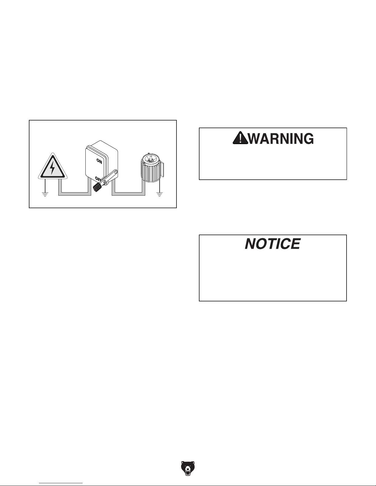
Since this machine must be permanently connected to the power supply, an extension cord
cannot be used.
Connection Type
A permanently connected (hardwired) power supply is typically installed with wires running through
mounted and secured conduit. A disconnecting
means, such as a locking switch (see following
figure), must be provided to allow the machine
to be disconnected (isolated) from the power
supply when required. This installation must be
performed by an electrician in accordance with all
applicable electrical codes and ordinances.
process. DO NOT connect to power until
In the event of a malfunction or breakdown,
grounding provides a path of least resistance
for electrical current to reduce the risk of electric
shock. A permanently connected machine must
be connected to a grounded metal permanent wiring system; or to a system having an equipmentgrounding conductor. All grounds must be verified
and rated for the electrical requirements of the
machine. Improper grounding can increase the
risk of electric shock!
Locking
Disconnect Switch
Power
Source
Ground
Grounding Instructions
Machine
ConduitConduit
Ground
Serious injury could occur if you connect
machine to power before completing setup
instructed later in this manual.
Extension Cords
Figure 9. Typical setup of a permanently
connected machine.
DO NOT use a phase converter to supply 3-Phase power, as it could damage
or decrease life of electrical components.
Damage caused by running this machine
with a phase converter will not be covered
under warranty.
-18-
Model G0841 (Mfd. Since 06/18)
SECTION 3: SETUP
This machine was carefully packaged for safe
transport. When unpacking, separate all enclosed
items from packaging materials and inspect them
for shipping damage.
,
please
IMPORTANT:
you are completely satisfied with the machine and
have resolved any issues between Grizzly or the
shipping agent. You MUST have the original pack-
aging to file a freight claim. It is also extremely
helpful if you need to return your machine later.
Keep children and pets away
from plastic bags or packing
materials shipped with this
Needed for Setup
This machine presents
serious injury hazards
to untrained users. Read
through this entire manual to become familiar with
the controls and operations before starting the
machine!
Wear safety glasses during
the entire setup process!
The following are needed to complete the setup
process:
• For Lifting and Moving:
— Two additional people
— A forklift or other power lifting equipment
rated for at least 7000 lbs.
— Four lifting straps rated for at least
7000 lbs. each
— A lifting safety hook rated for at least
7000 lbs.
• For Power Connection:
— A power source that meets minimum
circuit requirements for machine (review
Power Supply on Page 17 for details)
— An electrician or qualified service person-
nel to ensure a safe and code-compliant
connection to power source
This is an extremely heavy machine! Serious
personal injury or death may occur if safe
lifting and moving methods are not followed. To be safe, you will need assistance
and power equipment when moving the
shipping crate and removing the machine
from the crate. Seek assistance from a
professional rigger if you are unsure about
your abilities or maximum load ratings of
your lifting equipment.
SUFFOCATION HAZARD!
• For Assembly:
— Safety glasses for each person
— Leather gloves for each person
— Disposable Shop Rags
— Cleaner/degreaser (see Page 21)
— Quality metal protectant lubricant
— Precision level at least 12" long
— Phillips Screwdriver #2
Unpacking
If items are damaged
call us immediately at (570) 546-9663.
Save all packaging materials until
Model G0841 (Mfd. Since 06/18)
machine. Discard immediately.
-19 -
Inventory
The following is a list of items shipped with your
machine. Before beginning setup, lay these items
out and inventory them.
If any non-proprietary parts are missing (e.g. a
nut or a washer), we will gladly replace them; or
for the sake of expediency, replacements can be
obtained at your local hardware store.
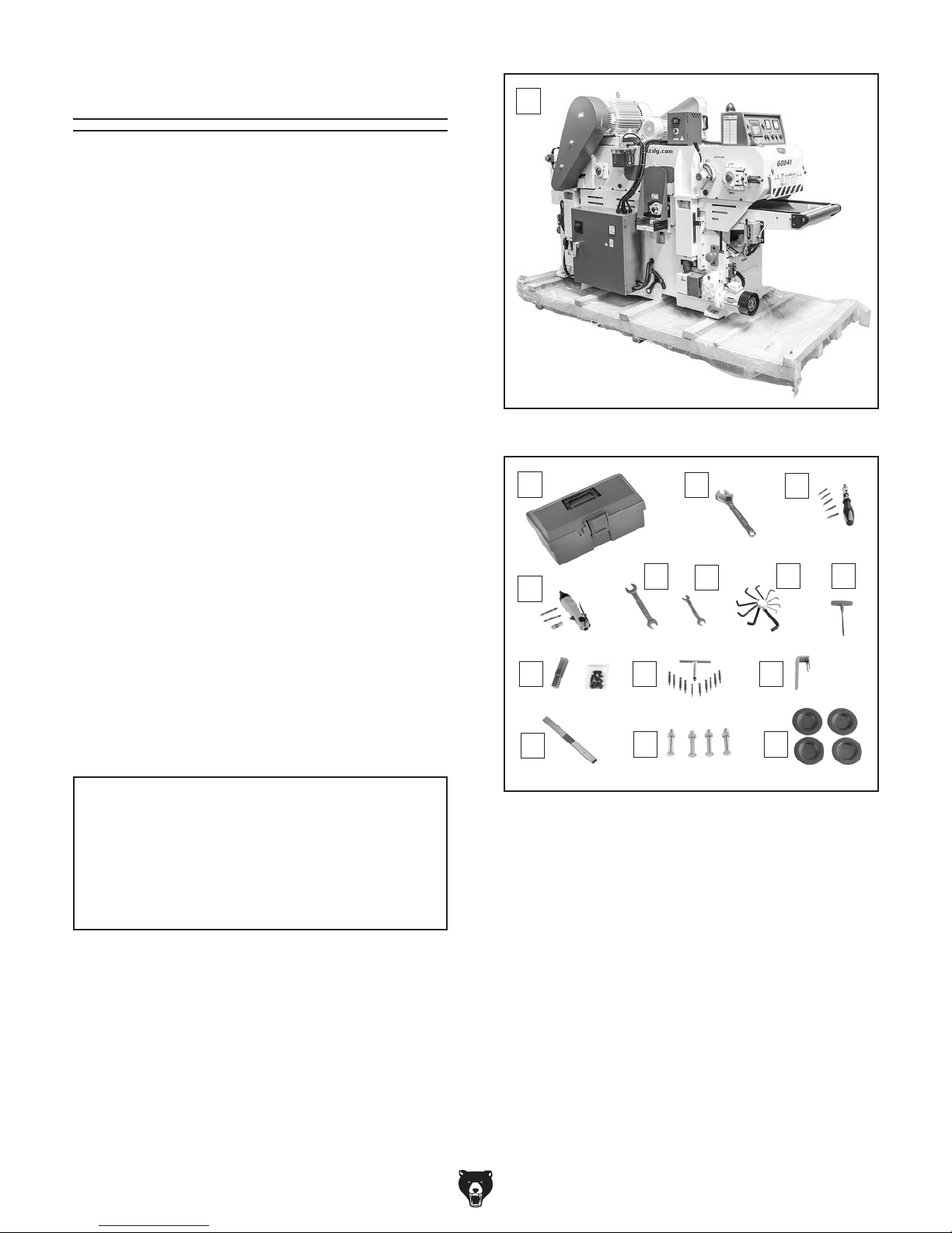
Inventory (Figures 10–11) Qty
A. Double-Sided Planer .................................. 1
B. Toolbox ....................................................... 1
C. Adjustable Wrench 10" ............................... 1
D. Ratcheting Drive
w/T-20 Torx Bits (5) .................................... 1
E. Pneumatic Screwdriver
w/Hose Adapter & Phillips Bits (2) .............. 1
F. Open-End Wrench 19/21mm ...................... 1
G. Open-End Wrench 12/14mm ...................... 1
H. Hex Wrench Set (1.5, 2, 2.5, 3, 4, 5, 5.5,
6, 8, 10mm) ................................................ 1
I. T-Handle Hex Wrench 4mm ....................... 1
J. Replacement Carbide Inserts (10-Pk)
w/Torx Head Screws M6-1 x 12 (20) .......... 1
K. T-Handle Drive
L. Electrical Panel Lock-out Handle ............... 1
M. Block Gauge ............................................... 1
N. Hex Bolts M16-1.5 x 75
w/Hex Nuts M16 -1.5 ................................... 4
O. Leveling Pads ............................................. 4
1
⁄4"
1
⁄4" w/T-20 Torx Bits (10) .... 1
A
Figure 10. Inventory—machine.
B
E
J K L
M
N
C
F
G
D
H I
O
NOTICE
If you cannot find an item on this list, carefully check around/inside the machine and
packaging materials. Often, these items get
lost in packaging materials while unpacking or they are pre-installed at the factory.
-20-
Figure 11. Inventory—tools.
Model G0841 (Mfd. Since 06/18)

Cleanup
The unpainted surfaces of your machine are
coated with a heavy-duty rust preventative that
prevents corrosion during shipment and storage.
This rust preventative works extremely well, but it
will take a little time to clean.
Be patient and do a thorough job cleaning your
machine. The time you spend doing this now will
give you a better appreciation for the proper care
of your machine's unpainted surfaces.
There are many ways to remove this rust preventative, but the following steps work well in a wide
variety of situations. Always follow the manufacturer’s instructions with any cleaning product you
use and make sure you work in a well-ventilated
area to minimize exposure to toxic fumes.
Before cleaning, gather the following:
• Disposable rags
• Cleaner/degreaser (WD•40 works well)
• Safety glasses & disposable gloves
• Plastic paint scraper (optional)
Basic steps for removing rust preventative:
Gasoline and petroleum
products have low flash
points and can explode
or cause fire if used to
clean machinery. Avoi d
using these products
to clean machinery.
Many cleaning solvents
are toxic if inhaled. Only
work in a well-ventilated
area.
NOTICE
Avoid chlorine-based solvents, such as
brake parts cleaner, that may damage
painted surfaces.
T23692—Orange Power Degreaser
A great product for removing the waxy shipping
grease from your machine during clean up.
1. Put on safety glasses.
2. Coat the rust preventative with a liberal
amount of cleaner/degreaser, then let it soak
for 5–10 minutes.
3. Wipe off the surfaces. If your cleaner/
degreaser is effective, the rust preventative
will wipe off easily. If you have a plastic paint
scraper, scrape off as much as you can first,
then wipe off the rest with the rag.
4. Repeat Steps 2–3 as necessary until clean,
then coat all unpainted surfaces with a quality
metal protectant to prevent rust. Aluminum
Figure 12. T23692 Orange Power Degreaser.
Model G0841 (Mfd. Since 06/18)
-21-
Site Considerations
Weight Load
Refer to the
of your machine. Make sure that the surface upon
which the machine is placed will bear the weight
of the machine, additional equipment that may be
installed on the machine, and the heaviest workpiece that will be used. Additionally, consider the
weight of the operator and any dynamic loading
that may occur when operating the machine.
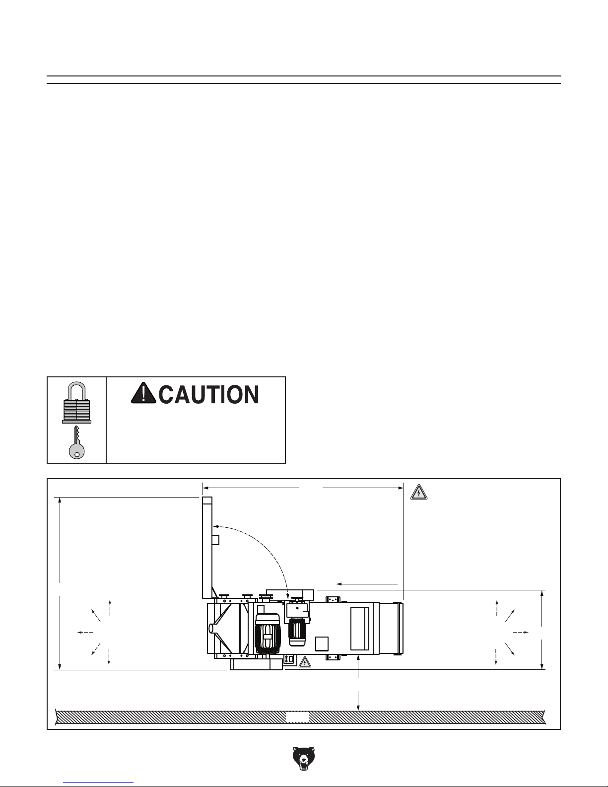
Space Allocation
Consider the largest size of workpiece that will
be processed through this machine and provide
enough space around the machine for adequate
operator material handling or the installation of
auxiliary equipment. With permanent installations,
leave enough space around the machine to open
or remove doors/covers as required by the maintenance and service described in this manual.
See below for required space allocation.
Physical Environment
Extreme conditions for this type of machinery are
Place this machine near an existing power source.
other hazards. Make sure to leave enough space
Shadows, glare, or strobe effects that may distract
Machine Data Sheet for the weight
Children or untrained people
may be seriously injured by
this machine. Only install in an
access restricted location.
The physical environment where the machine is
operated is important for safe operation and longevity of machine components. For best results,
operate this machine in a dry environment that is
free from excessive moisture, hazardous chemicals, airborne abrasives, or extreme conditions.
generally those where the ambient temperature
range exceeds 41°–104°F; the relative humidity
range exceeds 20%–95% (non-condensing); or
the environment is subject to vibration, shocks,
or bumps.
Electrical Installation
Make sure all power cords are protected from
traffic, material handling, moisture, chemicals, or
around machine to disconnect power supply or
apply a lockout/tagout device, if required.
Lighting
Lighting around the machine must be adequate
enough that operations can be performed safely.
or impede the operator must be eliminated.
108"
= Electrical Connection
79"
Keep Outfeed
Area Unobstructed
Figure 13. Minimum working clearances.
-22-
Feed
Direction
Min. 48" for Maintenance
Wall
Keep Infeed
Unobstructed
Area
Model G0841 (Mfd. Since 06/18)
39"
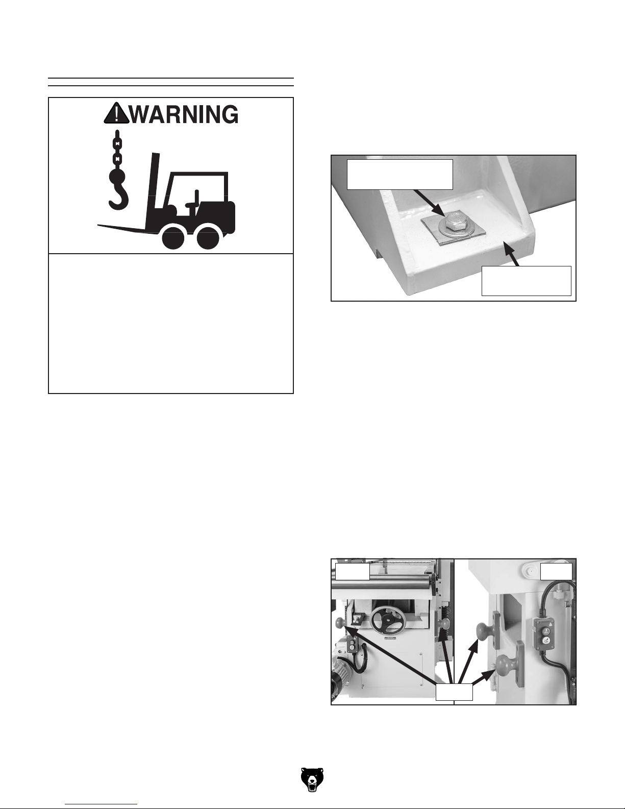
Lifting & Placing
3. Remove (4) lag screws and flat wash-
ers that secure machine to shipping pallet
(see Figure 14).
IMPORTANT: Take care not to damage
threaded holes in machine footings when
removing lag screws.
Lag Screw and Flat
Washer (1 of 4)
This is an extremely heavy machine! Serious
personal injury or death may occur if safe
lifting and moving methods are not followed. To be safe, you will need assistance
and power equipment when moving the
shipping crate and removing the machine
from the crate. Seek assistance from a
professional rigger if you are unsure about
your abilities or maximum load ratings of
your lifting equipment.
DO NOT attempt to lift or move machine without
using proper lifting equipment (such as forklift or
crane) and assistance from other people. Each
piece of lifting equipment must be rated for at
least 7000 lbs. to support dynamic loads that
may be applied while lifting.
Review the Power Supply section beginning on
Page 17, then prepare a permanent location for
the machine.
Machine Footing
(1 of 4)
Figure 14. Machine secured to shipping pallet.
4. Carefully lift machine off shipping crate.
Below are two methods for performing
this operation. Use best method for your
situation.
— Secure lifting straps around (4) cleats
on machine (see Figure 15) and attach
straps to lifting equipment with heavyduty shackles or other rigging equipment.
Cleats are positioned on machine to balance weight of machine when using four
lifting straps of equal length.
IMPORTANT: Eye bolts on top of motors
are for lifting the motors only. DO NOT lift
machine by eye bolts.
IMPORTANT: Make sure prepared location is
clean and level.
To lift and place machine:
1. Move machine near its prepared location
while still inside shipping crate.
2. Remove top and sides of shipping crate, then
place small items aside in safe location.
Model G0841 (Mfd. Since 06/18)
Front Rear
Cleats
Figure 15. Location of lifting cleats.
-23-
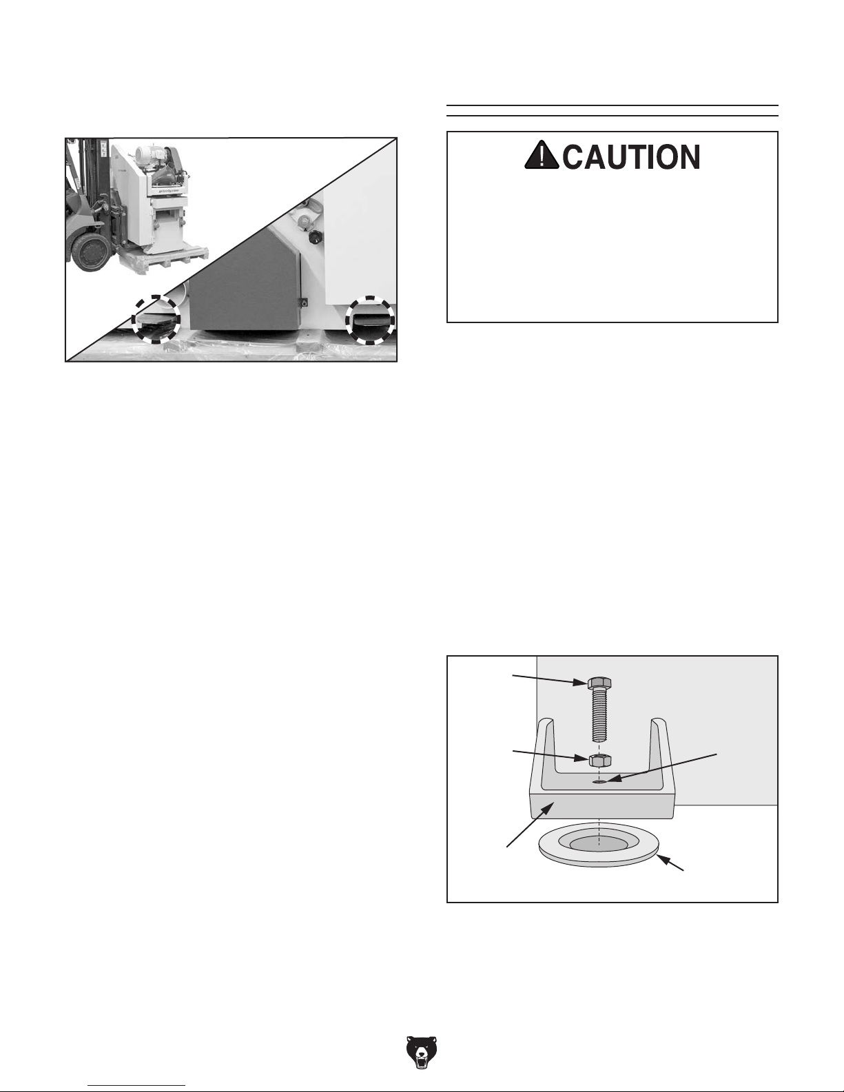
— Insert forklift forks through slots on bottom
of machine (see Figure 16). Slots are 36"
on center and accept forks up to 6" wide.
Figure 16. Example of lifting machine with
forklift.
5. Raise machine a couple of inches and check
balance of load. If using straps, have two
other people carefully steady machine to help
prevent it from swinging.
6. Raise machine enough to clear shipping pallet and carefully remove pallet.
7. Slowly lower machine into position.
Leveling
Leveling
For accurate planing results and to prevent
warping or twisting of cast iron base,
machine MUST be leveled from side to side
and from front to back on both ends.
Re-check the machine 24 hours after
installation, two weeks after that, and then
annually to make sure it remains level.
Leveling machinery helps precision components
remain straight and flat during the lifespan of the
machine. Components on an improperly leveled
machine may slowly twist due to the dynamic
loads placed on the machine during operation.
To level machine:
1. Slide (4) leveling pads under (4) footings at
corners of machine, as shown in Figure 17.
Make sure center of threaded hole in footing
aligns with center of leveling pad.
2. Insert (4) M16-1.5 x 75 hex bolts with (4) M16-
1.5 jam nuts into (4) threaded holes in footings, as shown in Figure 17.
-24-
Hex Bolt
Jam Nut
Footing
Leveling Pad
Figure 17. Leveling hardware orientation
(1 of 4).
Model G0841 (Mfd. Since 06/18)
Threaded
Hole
 Loading...