

GREAT PLANES Spirit of St. Louis Instruction Manual

WARRANTY
Great Planes®Model Manufacturing Co. guarantees this kit to be free from defects in both material and workmanship
at the date of purchase. This warranty does not cover any component parts damaged by use or modification. In no case
shall Great Planes’ liability exceed the original cost of the purchased kit. Further, Great Planes reserves the right
to change or modify this warranty without notice.
In that Great Planes has no control over the final assembly or material used for final assembly, no liability shall be
assumed nor accepted for any damage resulting from the use by the user of the final user-assembled product. By the act
of using the user-assembled product, the user accepts all resulting liability.
If the buyers are not prepared to accept the liability associated with the use of this product, they are advised
to return this kit immediately in new and unused condition to the place of purchase.
READ THROUGH THIS INSTRUCTION MANUAL
FIRST. IT CONTAINS IMPORTANT INSTRUCTIONS
AND WARNINGS CONCERNING THE ASSEMBLY
AND USE OF THIS MODEL.
GPMZ0240 for GPMA1151 V1.0Entire Contents © Copyright 2002
1610 Interstate Drive Champaign, IL 61822
(217) 398-8970, Ext. 2
airsupport@greatplanes.com
INSTRUCTION MANUAL
ELECTRIC PARKFLYER
INTRODUCTION . . . . . . . . . . . . . . . . . . . . . . . . . . . . . . 2
PRECAUTIONS. . . . . . . . . . . . . . . . . . . . . . . . . . . . . . . 2
ADDITIONAL ITEMS REQUIRED . . . . . . . . . . . . . . . . . 3
Flight Equipment . . . . . . . . . . . . . . . . . . . . . . . . . . . . 3
Building Supplies . . . . . . . . . . . . . . . . . . . . . . . . . . . . 4
IMPORTANT BUILDING NOTES . . . . . . . . . . . . . . . . . . 4
Parts Layout. . . . . . . . . . . . . . . . . . . . . . . . . . . . . . . . 4
PARTS DRAWINGS . . . . . . . . . . . . . . . . . . . . . . . . . . . 5
ASSEMBLY . . . . . . . . . . . . . . . . . . . . . . . . . . . . . . . . . . 6
Assemble the Tail Surfaces . . . . . . . . . . . . . . . . . . . . . 6
Assemble the Battery Holder . . . . . . . . . . . . . . . . . . . 7
Assemble the Fuselage . . . . . . . . . . . . . . . . . . . . . . . 8
Install the Servos . . . . . . . . . . . . . . . . . . . . . . . . . . . 10
Hook Up the Controls . . . . . . . . . . . . . . . . . . . . . . . . 11
Assemble the Landing Gear . . . . . . . . . . . . . . . . . . . 12
Mount the Motor . . . . . . . . . . . . . . . . . . . . . . . . . . . . 14
Assemble the Wing. . . . . . . . . . . . . . . . . . . . . . . . . . 16
FINAL ASSEMBLY . . . . . . . . . . . . . . . . . . . . . . . . . . . 19
PREPARE THE MODEL FOR FLYING . . . . . . . . . . . . . 20
Set the Control Throws . . . . . . . . . . . . . . . . . . . . . . . 20
Balance the Model (C.G.) . . . . . . . . . . . . . . . . . . . . . 20
Identify Your Model . . . . . . . . . . . . . . . . . . . . . . . . . . 21
Charge the Transmitter Batteries. . . . . . . . . . . . . . . . 21
Ground Inspection . . . . . . . . . . . . . . . . . . . . . . . . . . 21
Range Check . . . . . . . . . . . . . . . . . . . . . . . . . . . . . . 21
Performance Tips . . . . . . . . . . . . . . . . . . . . . . . . . . . 21
Motor Safety Precautions . . . . . . . . . . . . . . . . . . . . . 21
AMA SAFETY CODE (excerpts). . . . . . . . . . . . . . . . . 22
FIND A SAFE PLACE TO FLY . . . . . . . . . . . . . . . . . . . 22
FLYING . . . . . . . . . . . . . . . . . . . . . . . . . . . . . . . . . . . . 22
Flight . . . . . . . . . . . . . . . . . . . . . . . . . . . . . . . . . . . . 23
Landing . . . . . . . . . . . . . . . . . . . . . . . . . . . . . . . . . . 23
ROG. . . . . . . . . . . . . . . . . . . . . . . . . . . . . . . . . . . . . 23
BALSA FAIRING PATTERNS . . . . . . . . . . . . . back cover
Thank you for purchasing the Great Planes Spirit of St.
Louis ARF. The Spirit of St. Louis ARF is a lightweight, slowflying
Park Flyer
that can be flown just about anywhere there
is an open area clear of obstacles. Since the Spirit of St.
Louis ARF is constructed mostly of molded plastic foam, it
is durable and does not require the application of film
coverings used on wood models. And, the Spirit of St. Louis
landing gear makes ROG (rise off ground) takeoffs from
smooth surfaces a snap.
1. Although the Spirit of St. Louis is a slow-flying electric
powered model, just the same as any R/C plane, it should
still be flown with care. Even while gliding with the motor off
the Spirit of St. Louis could possibly cause injury to yourself
or spectators and damage property.
2. You must assemble the Spirit of St. Louis according to
the instructions. Modifications may reduce performance. In
cases where the instructions differ from the photos, the
written instructions are correct.
3.You must use a R/C radio system that is reliable and in good
condition. You must properly install all components so that the
model operates correctly on the ground and in the air.
4. You must check the operation of the model before every
flight to insure that all equipment is operating and that the
model has remained structurally sound.
Remember: Take your time and follow the instructions to
end up with a well-built model that is straight and true.
NOTE:We, as the kit manufacturer, provide you with a top quality
kit and great instructions, but ultimately the quality of your
finished model depends on how you build it; therefore, we cannot
in any way guarantee the performance of your completed model,
and no representations are expressed or implied as to the
performance or safety of your completed model.
PROTECT YOUR MODEL,YOURSELF
& OTHERS...FOLLOW THESE
IMPORTANT SAFETY PRECAUTIONS
INTRODUCTION
TABLE OF CONTENTS
2

Before starting to build, compare the parts in this kit with
the Parts List, and note any missing parts. Also inspect
all parts to make sure they are of acceptable quality. If
any parts are missing, broken or defective, or if you have
any questions about building or flying this airplane,
please call us at (217) 398-8970, or e-mail us at:
productsupport@greatplanes.com.
If you are contacting us for replacement parts, please be
sure to provide the full kit name (Great Planes Spirit of St.
Louis ARF) and the part numbers as listed in the Parts List.
You can also check our web site for the latest Spirit of
St. Louis ARF updates.
www.greatplanes.com
To make your R/C modeling experience totally enjoyable, if
this is your first R/C model, we recommend that you get the
assistance of an experienced pilot. If you’re not currently a
member of an R/C club, your local hobby shop has
information about clubs in your area whose membership
includes experienced pilots.
If you’re not already an Academy of Model Aeronautics
(AMA) member, we strongly urge you to join. There are over
2,500 AMA chartered clubs across the country. Among
other benefits, the AMA provides insurance to its members
who fly at sanctioned sites and events. Additionally, training
programs and instructors are available at AMA club sites to
help you get started the right way. Contact the AMA at the
address or toll-free phone number below:
Academy of Model Aeronautics
5151 East Memorial Drive
Muncie, IN 47302-9252
Tele. (800) 435-9262
Fax (765) 741-0057
Or via the Internet at: http://www.modelaircraft.org
The Spirit of St. Louis ARF requires a three-channel radio
with two micro servos, a mini/micro receiver and a speed
control. Hobbico®CS-5
Nano
™
servos (HCAM0090), the
Great Planes
ElectriFly
™
receiver (GPML0040 Hi Band,
GPML0041 Low Band) and the Great Planes C-5
(GPMM2000) or C-10 (GPMM2010) speed control are
recommended. The receiver comes without a crystal, which
must be purchased separately. The order number for the
crystal is FUTL63** (Hi Band) or FUTL62** (Low Band).
Substitute the “**” with the channel number you require. For
example, if the transmitter you plan to fly The Spirit of St.
Louis ARF with is on channel 44, order receiver crystal
FUTL6344. Hi Band receivers are tuned for channels 36 –
60. Low Band receivers are tuned for channels 11 – 35.
Additionally, an 8-cell (9.6 volt) 150 to 350 mAh battery pack
(GPMP0050 – 150 mAh, shown in photo, GPMP0060 – 270
mAh, GPMP0070 – 350 mAh) is required. For charging the
battery, the Great Planes ElectriFly Peak Charger
(GPMM3000) is recommended.
Flight Equipment
ADDITIONAL ITEMS REQUIRED
3
In addition to common household tools, here is the list of
items used to build The Spirit of St. Louis ARF.
❏ 6-minute epoxy (GPMR6042)
❏ 1/2 oz. Medium CA+ (GPMR6007)
❏ Hobby knife (HCAR0105)
❏ #11 blades (HCAR0211)
❏ Builder’s triangle (HCAR0480)
❏ Drill and 1/16” drill bit
❏ Double-sided foam tape (GPMQ4440) for mounting
receiver and speed control
❏ Sandpaper and sanding block
❏ Small Phillips screwdriver (#1)
❏ Small T-pins (HCAR5100) or craft pins
·
Since The Spirit of St. Louis ARF is made mostly of foam,
and since CA adhesives commonly used to build R/C model
airplanes dissolve foam, CA should not be used when gluing
foam parts. Therefore, 6-minute epoxy, which is compatible
with foam, is used for most of the construction. Unless
otherwise specified in the instructions, 6-minute epoxy is to
be used for gluing all parts of the model together. There are
a few instances where CA may be used for gluing wood to
wood.You can also use aliphatic resin glue instead of epoxy
if desired.
·
For the strongest bond apply epoxy to both parts being joined.
·
Before beginning construction, refer to the parts drawings
and use a ballpoint pen to write the part number on all the
wood parts.
Important Building NotesBuilding Supplies
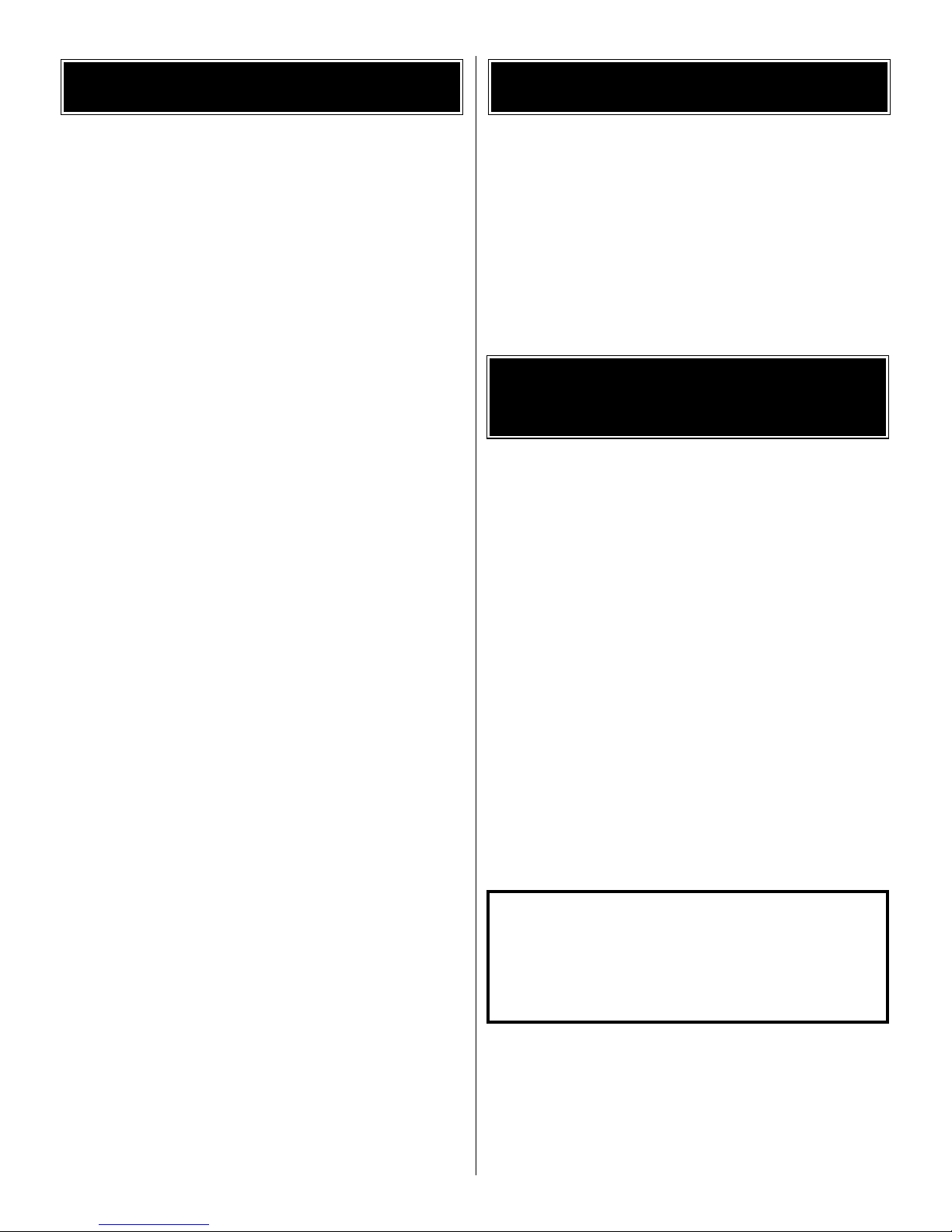
4
1. Cowl
2. Spinner
3. Spinner base
4. Cylinders
5. Landing gear wires
6. Wheel covers
7. Wheels
8. Pushrods
9. Motor, gearbox and propeller
10. Landing gear fairings
Parts Layout
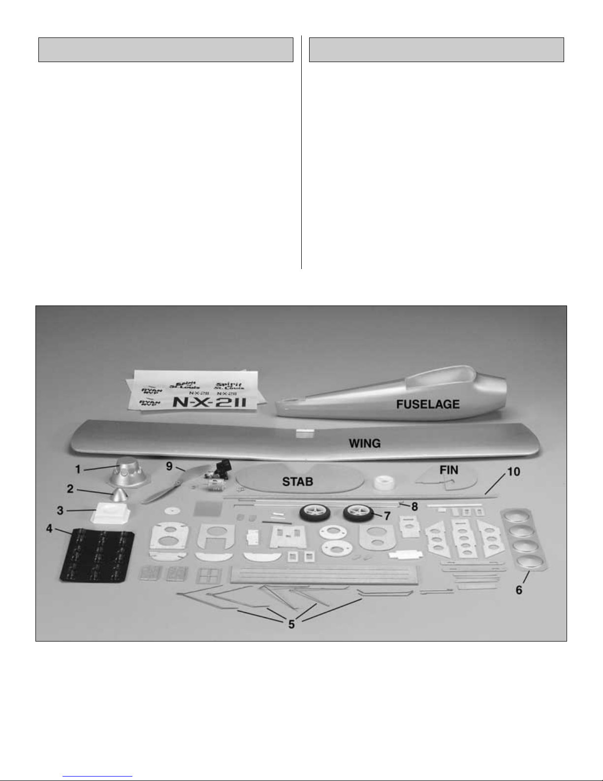
All other wood parts are identified on the following page.
5
PARTS DRAWINGS (not actual size)
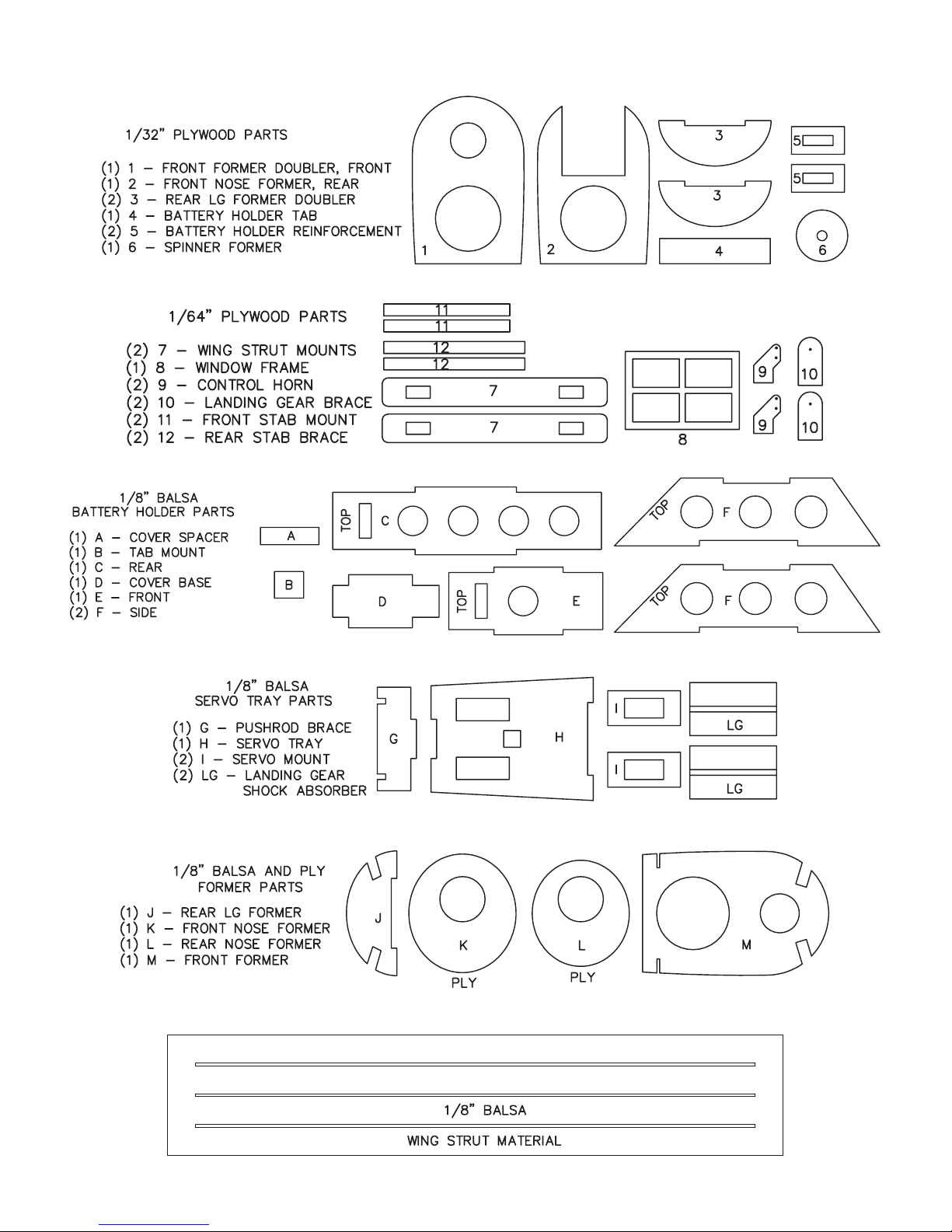
❏ 1. Using the precut lines as a guide, use a sharp hobby
knife to cut the rudder from the fin and the elevator from
the stabilizer (stab).
❏ 2. Sand a bevel to the bottom of the leading edge of the
elevator. The elevator is upside-down when the slot for the
control horn is on the left side.
❏ 3. Lay the stab and elevator on your workbench with the
slot in the elevator on the right side. Be certain there is a
1/32” gap between the elevator and the stab. Use one piece
of cellophane tape on the top to join the elevator to the stab.
❏ 4. Sand a bevel to one side of the rudder (it doesn’t
matter which side), then use cellophane tape to join the
rudder to the fin just the same as you joined the elevator to
the stab.
❏ 5. Use a hobby knife to carefully widen the slot in the
rudder and the elevator for the 1/64” plywood control horns
(9). Only a small sliver of foam is to be removed.
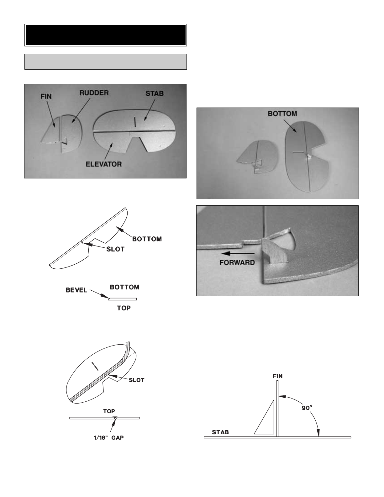
❏ 6. Enlarge the holes in the control horn for the pushrod
wire with a T-pin. Glue the control horns into the slots. Be
certain the elevator control horn is on the bottom and the
rudder control horn is on the left (the stab and elevator are
shown upside-down in the photo). Also be certain the
control horns are facing forward.
❏ 7. Use epoxy to glue the fin to the stab. Use a small
builder’s square to get the fin perpendicular to the stab, then
use tape or small T-pins to hold them together until the
epoxy hardens.
Assemble the Tail Surfaces
ASSEMBLY
6
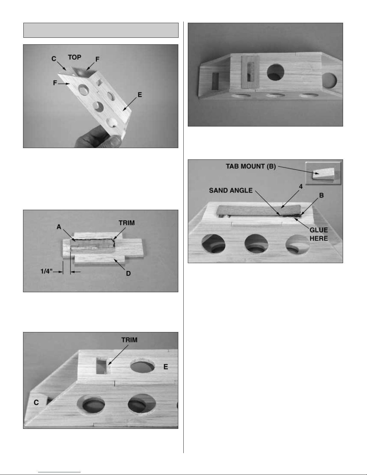
❏ 1. Without using any glue, assemble the 1/8” balsa parts
of the battery holder (C, E, F, F) as shown in the photo.
Once all the parts are joined, use medium CA to
permanently hold them together. Be sure the parts are
square to each other, not twisted.
Note: The cutouts in C and E are at the top. Parts F are
oriented with the end that has the steeper slope at the top.
❏ 2. Build the battery holder cover from parts A and D.
Glue A ¼” from the end of D as shown in the photo. Note:
You may need to trim the end of A to get it to fit into the
battery holder properly.
❏ 3. The cutouts in C and E may need to be trimmed at an
angle to allow the battery holder cover to fit properly in the
battery holder.
❏ 4. Glue the two 1/32” x 11/16 x 1-3/8” [1 x 18 x 34mm] ply
battery holder reinforcement (5) around the cutouts in
parts C and E as shown in the photo.
❏ 5. Fit the battery holder cover into the battery holder. Glue
the tab (4) and the tab mount (B) to the holder as shown.
The tab will hold the cover in position, until removal or
installation of the battery is required. Note: Sanding the tab
mount at an angle as shown in the photo will increase the
pressure on the cover.
Assemble the Battery Holder
7
Due to the manufacturing process, there may be some
small surface stress marks on the fuselage and wing. This
is normal.
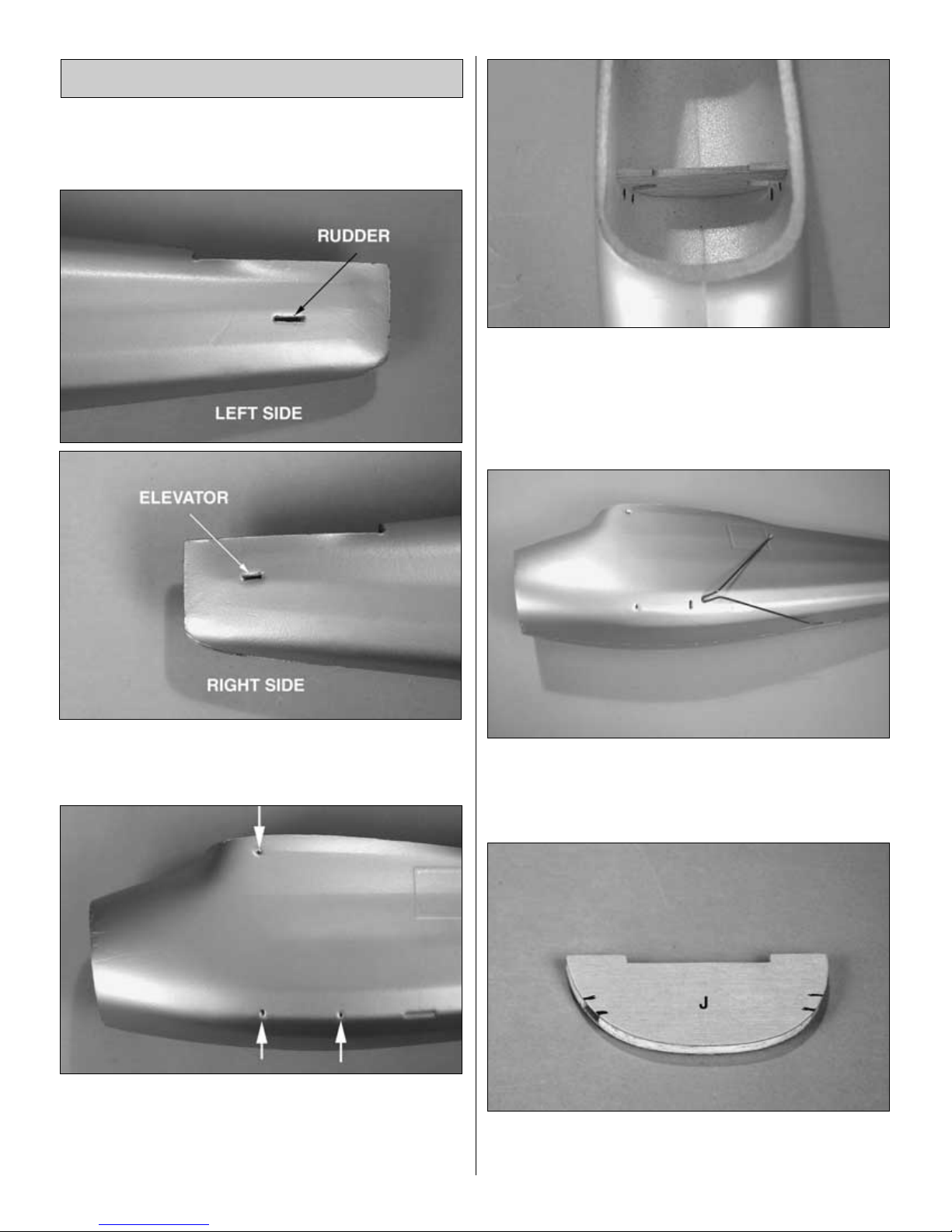
❏ 1. Using the indentations in the aft end of the fuselage as a
guide, cut the slots for the elevator and rudder pushrods. Do
not cut the slots for the stab braces until instructed to do so.
❏ 2. Use one of the landing gear wires to punch a hole at
the three marked locations for the landing gear on each side
of the fuselage. These holes will be used to align the
formers that will be installed in the fuselage. The left
fuselage side is shown in the above photo.
❏ 3.Temporarily fit the 1/8” balsa rear landing gear former
(J) into the fuselage. Be certain it is centered on the rear
two holes you punched in the fuselage sides. Use a finepoint felt-tip pen to mark the inside of the fuselage for the
landing gear wires on both sides of the slot in the landing
gear former.
❏ 4. Remove the landing gear former. Cut a slot in the
fuselage from the inside, centered in the groove, from one
mark to the other. Use one of the aft landing gear wires as
a guide for cutting the width and height of the slot.
❏ 5. Use medium CA to glue both 1/32” plywood doublers
(3) to both sides of former J. Mark the ply doublers at the
location of the slots in former J.
Assemble the Fuselage
8
 Loading...