

GREAT PLANES Spirit Elite ARF Instruction Manual
WARRANTY
Great Planes
®
Model Manufacturing Co. guarantees this kit to be free from defects in both material and workmanship at the date of
purchase. This warranty does not cover any component parts damaged by use or modification. In no case shall Great Planes’ liability
exceed the original cost of the purchased kit. Further, Great Planes reserves the right to change or modify this warranty without notice.
In that Great Planes has no control over the final assembly or material used for final assembly, no liability shall be assumed nor
accepted for any damage resulting from the use by the user of the final user-assembled product. By the act of using the user-assembled
product, the user accepts all resulting liability.
If the buyer is not prepared to accept the liability associated with the use of this product, the buyer is advised to return this
kit immediately in new and unused condition to the place of purchase.
READ THROUGH THIS MANUAL BEFORE
STARTING CONSTRUCTION. IT CONTAINS
IMPORTANT WARNINGS AND INSTRUCTIONS
CONCERNING THE ASSEMBLY AND USE OF
THIS MODEL.
GPMZ0234 for GPMA1047 V1.1© Copyright 2002
1610 Interstate Drive Champaign, IL 61822
(217) 398-8970, Ext 2
airsupport@greatplanes.com
INSTRUCTION MANUAL
Wingspan: 78.5 in. [1981mm]
Wing Area: 645 sq. in. [41.6 sq dm]
Weight: 46 - 48 oz. [1304 - 1360g]
Wing Loading: 10.3 - 10.7 oz./sq. ft. [31.4 - 32.6 g/sq dm]
Length: 46 in. [1168mm]
Radio: 4 - 6 Channel (4 servo wing mixing functions required for advanced set-ups - see the back pages of this manual)
TM

INTRODUCTION................................................................2
SAFETY PRECAUTIONS ..................................................2
ADDITIONAL ITEMS REQUIRED .....................................3
Hardware and Accessories ................................................3
Adhesives and Building Supplies .......................................3
Optional Supplies and Tools...............................................3
IMPORTANT BUILDING NOTES.......................................3
ORDERING REPLACEMENT PARTS...............................4
METRIC CONVERSION RULER.......................................4
KIT CONTENTS.................................................................5
WING ASSEMBLY .............................................................6
Install the Ailerons and Flaps.............................................6
Install the Aileron and Flap Servos ....................................6
Install the Wing Dowels and Bolt Plates ............................7
FUSELAGE ASSEMBLY ...................................................8
Mounting the Wing .............................................................8
Install the Stabilizer (Stab) .................................................9
Install the Fin....................................................................10
Align the Tail .....................................................................11
Install the Elevator and Rudder........................................11
Install the Elevator and Rudder Servos............................11
Install the Elevator and Rudder Pushrods........................12
Install the Receiver and Battery .......................................14
FINAL ASSEMBLY ..........................................................14
Install the Tow Hook .........................................................14
Hook Up the Wing Servos................................................15
Attach the Canopy............................................................16
BALANCE THE MODEL..................................................18
BALANCE THE MODEL LATERALLY ............................18
CONTROL SURFACE THROWS .....................................18
TOW HOOK LOCATION ..................................................18
PREFLIGHT .....................................................................18
Identify Your Model ...........................................................18
Charge the Batteries ........................................................18
Range Check....................................................................18
AMA SAFETY CODE ......................................................19
General.............................................................................19
Radio Control ...................................................................19
CHECKLIST.....................................................................19
FLYING.............................................................................20
Trimming Flights ...............................................................20
Hi-Start Launch ................................................................20
First Flights.......................................................................20
ADVANCED FEATURES .................................................21
FACTS ABOUT THERMALS ...........................................21
THERMAL SOARING ......................................................22
SLOPE SOARING............................................................22
BALLAST.........................................................................22
Thank you for purchasing the Great Planes Spirit Elite ARF
sailplane. Soaring offers a freedom that no other type of
flying can provide! With a little practice and some help from
Mother Nature, you will be able to defy gravity and enjoy
flights that can last for hours.
The Spirit Elite's high performance airfoils give the aircraft a
superior Lift to Drag (L/D) ratio with outstanding performance
in a high variety of wind conditions. The advanced wing
design features flaps and ailerons to provide the ultimate in
control when using computer radio mixing functions.
Take your time and follow the directions carefully to end
up with a well-built model that is straight and true.
For the latest technical updates or manual corrections for
the Spirit Elite ARF, visit the web site listed below and select
the Great Planes Spirit Elite ARF. If there is new technical
information or changes to this kit, a “tech notice” box will
appear in the upper left corner of the page.
http://www.greatplanes.com/airplanes/index.html
1. Your Spirit Elite ARF should not be considered a toy, but
rather a sophisticated, working model that functions very
much like a full-size sailplane. Because of its performance
capabilities, the Spirit Elite ARF, if not assembled and
operated correctly, could possibly cause injury to yourself or
spectators and damage to property.
2. You must assemble the model according to the
instructions. Do not alter or modify the model, as doing so
may result in an unsafe or unflyable model. In a few cases
the instructions may differ slightly from the photos. In those
instances the written instructions should be considered
as correct.
3. You must take time to build straight, true and strong.
4. You must use an R/C radio system that is in firstclass condition.
5. You must correctly install all R/C and other components so
that the model operates correctly on the ground and in the air.
6. You must check the operation of the model before every
flight to insure that all equipment is operating and that the
model has remained structurally sound. Be sure to check
clevises or other connectors often and replace them if they
show any signs of wear or fatigue.
PROTECT YOUR MODEL,YOURSELF
& OTHERS...FOLLOW THESE
IMPORTANT SAFETY PRECAUTIONS
INTRODUCTIONTABLE OF CONTENTS
2
7. If you are not already an experienced R/C pilot, you
should fly the model only with the help of a competent,
experienced R/C pilot.
Remember:Take your time and follow the instructions to
end up with a well-built model that is straight and true.
If you have not flown this type of model before, we
recommend that you get the assistance of an experienced
pilot in your R/C club for your first flights. If you're not a
member of a club, your local hobby shop has information
about clubs in your area whose membership includes
experienced pilots.
In addition to joining an R/C club, we strongly recommend
you join the AMA (Academy of Model Aeronautics). AMA
membership is required to fly at AMA sanctioned clubs.There
are over 2,500 AMA chartered clubs across the country.
Among other benefits, the AMA provides insurance to its
members who fly at sanctioned sites and events. Additionally,
training programs and instructors are available at AMA club
sites to help you get started the right way. Contact the AMA
at the address or toll-free phone number below:
Academy of Model Aeronautics
5151 East Memorial Drive
Muncie, IN 47302-9252
Tele. (800) 435-9262
Fax (765) 741-0057
Or via the Internet at:
http://www.modelaircraft.org
❏ Radio with at least 4 channels (a minimum of a 5-channel
radio with mixing functions is required for the advanced
features)
❏ (6) mini servos (FUTM0033 S3101 servos recommended)
❏ Hi-Start or other launching device (DYFP8302)
❏ 1/4" Foam Rubber Padding (HCAQ1000)
❏ (2) 24" Servo Extensions (HCAM2200)
❏ (2) 6" Servo Extentions (HCAM2000)
❏ (2) “Y” Harnesses (HCAM2500, only one required for
advanced features)
❏ (2) 12" Servo Extensions (HCAM2100, required for
advanced features only)
❏ 1/2 oz. Thin Pro CA (GPMR6001)
❏ 1/2 oz. Medium Pro CA+ (GPMR6007)
❏ 30-Minute Epoxy (GPMR6047)
❏ Hobby knife (HCAR0105)
❏ #11 blades (HCAR0211)
❏ Builder's triangle (HCAR0480)
❏ Electric drill and drill bits
❏ #1 Phillips screwdriver (HCAR1022)
❏ Pliers with wire cutter (HCAR0630)
Here is a list of optional tools that will help you build the
Spirit Elite ARF.
❏ Great Planes CG Machine™ (GPMR2400)
❏ Straightedge with scale (HCAR0475)
❏ Cutting mat (HCAR0456)
❏ CA Applicator tips (GPMR6033)
❏ CA Debonder (GPMR6039)
❏ CA accelerator (GPMR6034)
❏ 6-Minute Epoxy (GPMR6045)
❏ Milled Fiberglass (GPMR6165)
❏ Mixing Sticks (GPMR8055)
❏ Denatured Alcohol (for epoxy clean up)
❏ Felt-Tip Marker (TOPQ2510)
❏ Rotary tool such as Dremel
❏ Sealing Iron (TOPR2100)
❏ Covering sock (TOPR2175)
❏ Great Planes AccuThrow
™
Deflection Gauge (for
measuring control throws, GPMR2405)
• There are two types of screws used in this kit:
Sheet metal screws are designated by a number and a
length. For example #6 x 3/4"
This is a number six screw that is 3/4" long.
Machine screws are designated by a number, threads per
inch and a length. For example 4-40 x 3/4"
This is a number four screw that is 3/4" long with
forty threads per inch.
IMPORTANT BUILDING NOTES
Optional Supplies and Tools
Adhesives and Building Supplies
Hardware and Accessories
ADDITIONAL ITEMS REQUIRED
We, as the kit manufacturer, provide you with a top quality
kit and instructions, but ultimately the quality and flyability
of your finished model depends on how you build it;
therefore, we cannot in any way guarantee the
performance of your completed model and no
representations are expressed or implied as to the
performance or safety of your completed model.
3

To convert inches to millimeters, multiply inches by 25.4
• When you see the term trial fit in the instructions, it
means that you should first position the part on the
assembly without using any glue, then slightly modify or
custom fit the part as necessary for the best fit.
• Whenever the term glue is written you should rely upon
your experience to decide what type of glue to use. When a
specific type of adhesive works best for that step, the
instructions will make a recommendation.
• Whenever just epoxy is specified you may use either 30minute (or 45-minute) epoxy or 6-minute epoxy. When 30minute epoxy is specified it is highly recommended that you
use only 30-minute (or 45-minute) epoxy, because you will
need the working time and/or the additional strength.
• Photos and sketches are placed before the step they
refer to. Frequently you can study photos in following steps
to get another view of the same parts.
• The Spirit Elite ARF is factory-covered with Top Flite
MonoKote film. Should repairs ever be required, MonoKote
can be patched with additional MonoKote purchased
separately. MonoKote is packaged in six-foot rolls, but some
hobby shops also sell it by the foot. If only a small piece of
MonoKote is needed for a minor patch, perhaps a fellow
modeler would give you some. MonoKote is applied with a
model airplane covering iron, but in an emergency a regular
iron could be used. The roll of MonoKote includes full
instructions for application. Following are the colors used on
this model and order numbers for six foot rolls.
White (TOPQ0204)
Sapphire Blue (TOPQ0226)
Teal (TOPQ0223)
Blue Mist (TOPQ0217)
4
To order replacement parts for the Great Planes Spirit Elite ARF, use the order numbers in the Replacement Parts List
that follows. Replacement parts are available only as listed. Not all parts are available separately (an aileron cannot be
purchased separately, but is only available with the wing kit). Replacement parts are not available from Product Support,
but can be purchased from hobby shops or mail order/Internet order firms. Hardware items (screws, nuts, bolts) are also
available from these outlets. If you need assistance locating a dealer to purchase parts, visit www.greatplanes.com and
click on “Where to Buy.” If this kit is missing parts, contact Great Planes Product Support.
Replacement Parts List
Order Number Description How to Purchase
Missing pieces ......................Contact Product Support
Instruction manual.................Contact Product Support
Full-size plans .......................Not available
GPMA1995......................................Fiberglass Fuse
GPMA1996......................................Wing Kit
GPMA1997......................................Tail Set
GPMA1998......................................Canopy
GPMA1999......................................Wing Joiner Rod
ORDERING REPLACEMENT PARTS
.............
Contact Your Hobby
Supplier to Purchase
These Items
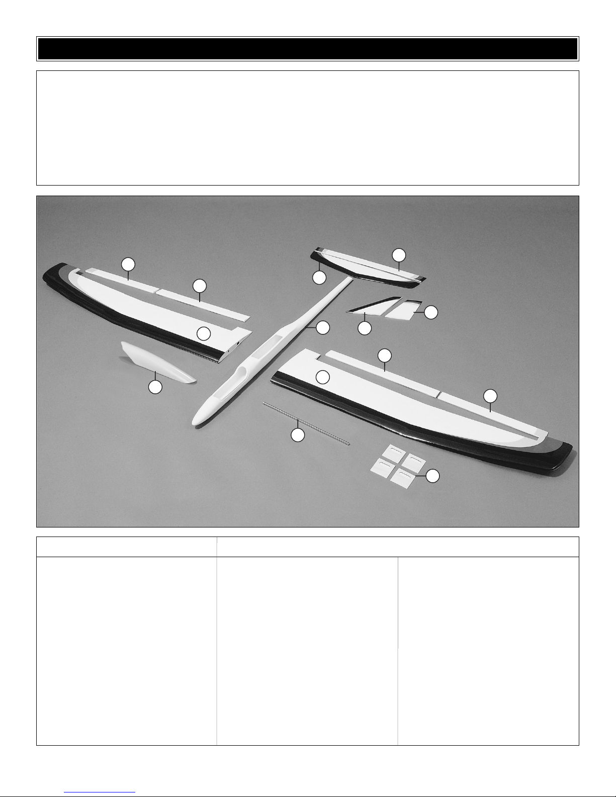
1 Fiberglass Fuselage
2 Wing Panels (Left and Right)
3 Ailerons (Left and Right)
4 Flaps (Left and Right)
5 Stabilizer
6 Elevator
7 Fin
8 Rudder
9 7mm x 340mm Joiner Rod
10 Aileron/Flap Servo Hatch Covers (4)
11 Canopy
(1) 3mm ply Servo Tray
(2) 3mm ply Servo Tray Doublers
(8) 5 x 10 x 10mm Hardwood Blocks
(1) Left Wing Bolt Plate
(1) Right Wing Bolt Plate
(2) 5mm Dowels
(1) 3mm Ply Pushrod Support
(1) 3mm Ply Canopy Frame
(2) 3mm Ply Wing Bolt Plates
(1) 4-40 Nut
(1) #4 Washer
(3) 4-40 Blind Nuts
(6) Clevis Retainer
(6) Nylon Clevis
(6) Faslink
(6) Small Control Horns
(2) 8-32 x 3/4" Cap Screws
(2) #8 Flat Washers
(16) #2 x 3/8" Sheet Metal Screws
(4) 2-56 x 3/8" Machine Screws
(8) 2-56 x 5/8" Machine Screws
(4) .074 x 4" Threaded One End
Pushrods
(2) .074" x 36" Elev/Rudder/throttle
Pushrods
(2) Outer Pushrod Tubes
(1) 2" x 9" CA Hinge Strip
(1) Eyelet
(1) 4-40 Tow Hook
(2) 3mm Ply Tow Hook Plates
Kit Contents (Photographed)
Kit Contents (Not Photographed)
Before starting to build, use the Kit Contents list to take an inventory of this kit to make sure it is complete and inspect
the parts to make sure they are of acceptable quality. If any parts are missing or are not of acceptable quality, or if you
need assistance with assembly, contact Great Planes Product Support. When reporting defective or missing parts, use
the part names exactly as they are written in the Kit Contents list on this page.
Great Planes Product Support:
Phone: (217) 398-8970
Fax: (217) 398-7721
E-mail: airsupport@greatplanes.com
KIT CONTENTS
5
3
4
2
11
5
1
7
2
9
6
8
4
3
10
❏ 1. Cut the 2" x 9" [51 x 229mm] sheet into 3/4" x 1"
[19 x 25mm] pieces.
❏ ❏ 2. Trial fit three hinges into each of the ailerons and
install onto the wing panels. Make sure the ailerons work
freely to full deflection.
❏ ❏ 3. Hold the aileron to full deflection and place three
drops of thin CA onto each hinge. Flip the wing over and
place three drops onto the other side of each hinge. Be
careful not to use too much CA or it may run down the hinge
line. Exercise the aileron several times to loosen it up.
❏ 4. Repeat for the other wing panel.
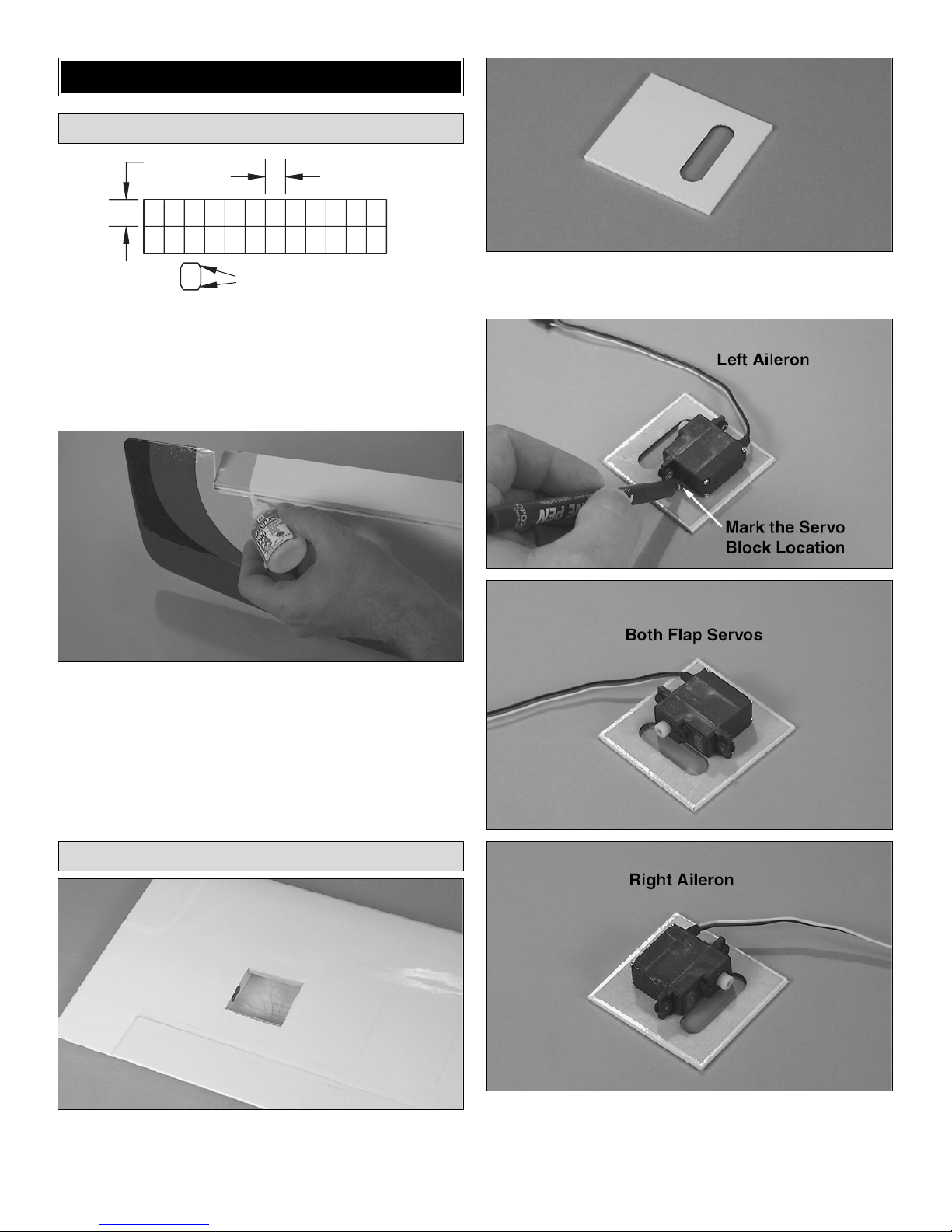
❏ 1. Locate the openings for the flap and aileron servos in
the bottom of each wing panel. Trim out the covering and
seal the edges using a sealing iron.
❏ 2. Locate the four servo hatch covers and trim out the
servo arm openings. Seal the edges using a sealing iron.
❏ 3. Trial fit your servos onto the covers and mark the
locations of the servo blocks. Note the orientation of the
servos and write the location of each servo on the cover.The
flap servos should be oriented the same for both wing panels.
Install the Aileron and Flap Servos
Install the Ailerons and Flaps
WING ASSEMBLY
6
1" [25mm]
3/4" [19mm]
Trim the Corners
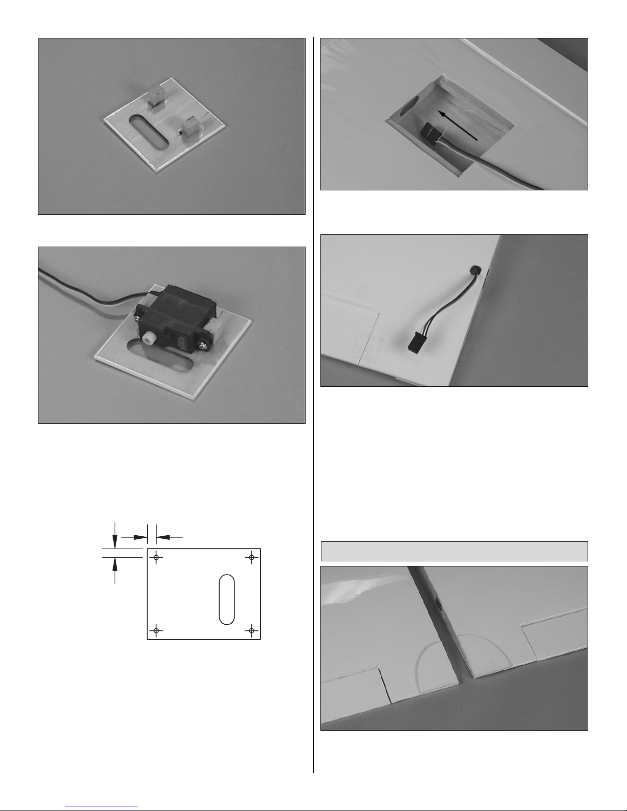
❏ ❏ 4. Using epoxy, glue the servo blocks to the hatch covers.
❏ ❏ 5. Attach the servos to the blocks using the hardware
that comes with your radio system. Hint: Drill a 1/16"
[1.5mm] pilot hole for the servo screws and strengthen the
holes with a drop of thin CA.
❏ ❏ 6. Temporarily install the servos into the wing. Mark and
drill a1/16" [1.5mm] pilot hole in the corners of the hatch covers.
❏ ❏ 7. Use thin CA to strengthen the holes in the wing.
❏ ❏ 8. Attach 24" [101mm] servo extensions to the aileron
servos.
Hint: It is a good idea to tape (or shrink wrap) the
connection since it will not be easily accessible in the future.
❏ ❏ 9. Tie the string to the extension and pull it through
the wing.
❏ ❏ 10. Trim out the servo wire access hole on the bottom
of the wing and route the wires through.
Hint: It's a good
idea to label each of the servo wires.
❏ 11. Repeat this procedure for the flap servo extension
and then the two servos in the other wing panel.
❏ 12.Temporarily, attach the hatch covers with the #2 x 3/8"
self-tapping screws. We will do final servo adjustments and
pushrod installation later.
❏ 1. Glue the two precovered wing bolt plates to the top of
the wing at the trailing edge.
Hint: Remove the covering
underneath for a good glue bond.
Install the Wing Dowels and Bolt Plates
7
1/8" [3mm]
1/8" [3mm]
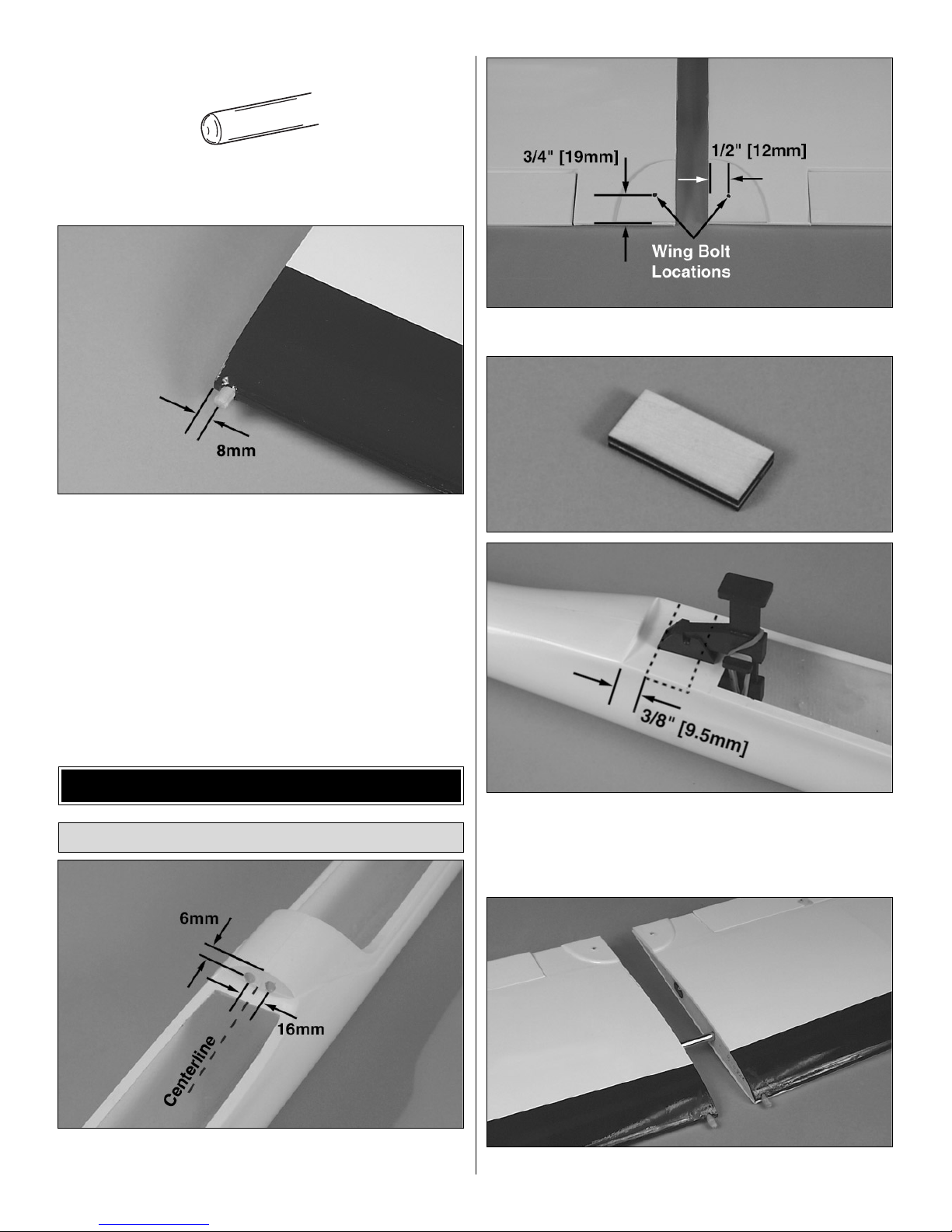
❏ 2. Round the front edge of the two 5mm dowels.
❏ 3. Trim off the covering that hides the dowel holes.Trial fit
the two wing dowels into the wing panels.
❏ 4. Using 30 minute epoxy, liberally coat the inside of the
hole and wing dowel. Insert the dowel until only 3/8" [5mm]
or so sticks out.
IMPORTANT: This is a very high stress
area. Take your time to get a nice strong glue joint.
Wipe off
the excess glue that squeezes out.
❏ 1. Carefully mark and drill two 3/16" [5mm] holes for the
wing dowels where shown.
❏ 2. Mark wing bolt locations onto the wing as shown.
❏ 3. Using epoxy, glue the two 2.5 x 20 x 41mm plywood
wing bolt plates together. After they are cured, glue them
inside the fuselage where shown. Be sure to use plenty of
glue to fill any unevenness inside the fuselage.
❏ 4. Slide the wing panels together using the 7mm wing joiner.
Mounting the Wing
FUSELAGE ASSEMBLY
8
 Loading...