

Page 1
™
INSTRUCTION MANUAL
Wingspan: 71.5 in [1815 mm]
2
Wing Area: 836 in
Wing Loading: 27−30 oz /ft
[53.9 dm2]
2
[82−92 g/dm2]
Length: 73 in [1855 mm]
WARRANTY
Great Planes Model Manufacturing® Co. guarantees this kit to
be free from defects in both material and workmanship at the
date of purchase. This warranty does not cover any component
parts damaged by use or modification. In no case shall Great
Planes’ liability exceed the original cost of the purchased kit.
Further, Great Planes reserves the right to change or modify this
warranty without notice.
In that Great Planes has no control over the final assembly or
material used for final assembly, no liability shall be assumed nor
accepted for any damage resulting from the use by the user of
the final user-assembled product. By the act of using the
user-assembled product, the user accepts all resulting liability.
If the buyer is not prepared to accept the liability associated
with the use of this product, the buyer is advised to return
Weight: 9.75− 10.75 lb
[4420 −4870 g]
Radio: 4– 6 channel
SPECIFICATIONS
Engine: 1.20 cu in [20cc] 2-stroke glow,
1.55 cu in [25cc] 4-stroke glow,
Rimfire 1.20 Brushless
electric
this kit immediately in new and unused condition to the
place of purchase.
To make a warranty claim send the defective part or item to
Hobby Services at the address below:
Hobby Services
3002 N. Apollo Dr. Suite 1
Champaign IL 61822 USA
Include a letter stating your name, return shipping address, as
much contact information as possible (daytime telephone
number, fax number, e-mail address), a detailed description of
the problem and a photocopy of the purchase receipt. Upon
receipt of the package the problem will be evaluated as quickly
as possible.
READ THROUGH THIS MANUAL BEFORE STARTING CONSTRUCTION. IT CONTAINS IMPORTANT
INSTRUCTIONS AND WARNINGS CONCERNING THE ASSEMBLY AND USE OF THIS MODEL.
© 2014 Great Planes Model Mfg. A subsidiary of Hobbico, Inc.
Champaign, Illinois
(217) 398-8970, Ext 5
airsupport@greatplanes.com
GPMA1232
Page 2
TABLE OF CONTENTS
INTRODUCTION
INTRODUCTION . . . . . . . . . . . . . . . . . . . . . . . . . . . . . . . . 2
SAFETY PRECAUTIONS . . . . . . . . . . . . . . . . . . . . . . . . . 3
ADDITIONAL ITEMS REQUIRED. . . . . . . . . . . . . . . . . . . 3
Engine Recommendations. . . . . . . . . . . . . . . . . . . . . . 3
Brushless Electric Motor . . . . . . . . . . . . . . . . . . . . . . . 3
Radio Equipment . . . . . . . . . . . . . . . . . . . . . . . . . . . . . 4
ADHESIVES, HARDWARE & OTHER ACCESSORIES. . 4
KIT INSPECTION . . . . . . . . . . . . . . . . . . . . . . . . . . . . . . . 5
ORDERING REPLACEMENT PARTS . . . . . . . . . . . . . . . 5
KIT CONTENTS. . . . . . . . . . . . . . . . . . . . . . . . . . . . . . . . . 5
ASSEMBLE THE WINGS . . . . . . . . . . . . . . . . . . . . . . . . . 6
ASSEMBLE THE FUSELAGE . . . . . . . . . . . . . . . . . . . . .8
Mount the Landing Gear . . . . . . . . . . . . . . . . . . . . . . . 8
Prepare the Fuselage for Mounting
the Engine (or Electric Motor) . . . . . . . . . . . . . . . . . . . 9
Mount a Glow Engine. . . . . . . . . . . . . . . . . . . . . . . . . 10
Hook Up the Throttle . . . . . . . . . . . . . . . . . . . . . . . . . 11
Install the Fuel Tank. . . . . . . . . . . . . . . . . . . . . . . . . . 11
Mount an Electric Motor . . . . . . . . . . . . . . . . . . . . . . . 12
Cut the Cowl . . . . . . . . . . . . . . . . . . . . . . . . . . . . . . . 16
Mount the Cowl . . . . . . . . . . . . . . . . . . . . . . . . . . . . . 18
Mounting the Cowl with Wood Screws . . . . . . . . . . . 21
Finish the Cowl . . . . . . . . . . . . . . . . . . . . . . . . . . . . . 22
Hook Up the Rudder and Elevators . . . . . . . . . . . . . . 22
FINAL ASSEMBLY . . . . . . . . . . . . . . . . . . . . . . . . . . . . . 24
Set the C.G. . . . . . . . . . . . . . . . . . . . . . . . . . . . . . . . . 24
Balance the Model Laterally . . . . . . . . . . . . . . . . . . . 25
Set the Control Throws . . . . . . . . . . . . . . . . . . . . . . . 25
PREFLIGHT . . . . . . . . . . . . . . . . . . . . . . . . . . . . . . . . . . . 25
Identify Your Model . . . . . . . . . . . . . . . . . . . . . . . . . . 25
Ground Check . . . . . . . . . . . . . . . . . . . . . . . . . . . . . . 25
Range Check . . . . . . . . . . . . . . . . . . . . . . . . . . . . . . . 26
ENGINE /MOTOR SAFETY PRECAUTIONS . . . . . . . . . 26
AMA SAFETY CODE (excerpts) . . . . . . . . . . . . . . . . . . . 27
General . . . . . . . . . . . . . . . . . . . . . . . . . . . . . . . . . . . 27
Radio Control . . . . . . . . . . . . . . . . . . . . . . . . . . . . . . . 27
CHECK LIST . . . . . . . . . . . . . . . . . . . . . . . . . . . . . . . . . . 27
FLYING. . . . . . . . . . . . . . . . . . . . . . . . . . . . . . . . . . . . . . . 28
OPTIONAL WOOD/FRP EP MOTOR MOUNT BOX . . . 28
ENGINE CUTOUT TEMPLATE FOR O.S. 1.55FS-a . . . 31
Congratulations and thank you for purchasing the Great Planes
Sequence 1.20 ARF! The Sequence may not have all of the
frills of your exclusive, composite pattern plane, but it’s still
a contender at a fraction of the price. And the Sequence’s
simplicity makes it the perfect entry for beginner/intermediate
pattern pilots or a great practice/backup ship for experienced
pilots. And while we’re at it, the Sequence is a great all-around
sport plane too!
NOTE: An optional wood motor mount for brushless electric
motors is available separately (GPMA4382). This mount allows
outrunners to be “front mounted” and has provisions for geared
inrunners. Full instructions for assembly and mounting are in
the back of the manual on page 28.
For the latest technical updates or manual corrections to
the Sequence 1.20 ARF visit the Great Planes web site at
greatplanes.com. Open the “Airplanes” link, then select the
Sequence 1.20 ARF. If there is new technical information or
changes to this model a “tech notice” box will appear in the
upper left corner of the page.
Academy of Model Aeronautics
If you are not already a member of the AMA, please join! The
AMA is the governing body of model aviation and membership
provides liability insurance coverage, protects modelers’ rights
and interests and is required to fl y at most R/C sites.
Academy of Model Aeronautics
5151 East Memorial Drive
Muncie, IN 47302-9252
Tele. (800) 435-9262
Fax (765) 741-0057
modelaircraft.org
IMPORTANT!!! Two of the most important things you can
do to preserve the radio controlled aircraft hobby are to avoid
fl ying near full-scale aircraft and avoid fl ying near or over
groups of people.
2
Page 3

SAFETY PRECAUTIONS
ADDITIONAL ITEMS REQUIRED
Protect Your Model, Yourself & Others…
Follow These Important Safety Precautions
1. Your Sequence 1.20 ARF should not be considered a toy,
but rather a sophisticated, working model that functions very
much like a full-size airplane. Because of its performance
capabilities, the Sequence, if not assembled and operated
correctly, could possibly cause injury to yourself or spectators
and damage to property.
2. You must assemble the model according to the instructions.
Do not alter or modify the model, as doing so may result in an
unsafe or unfl yable model. In a few cases the instructions may
differ slightly from the photos. In those instances the written
instructions should be considered as correct.
3. You must take time to build straight, true and strong.
4. You must use an R/C radio system that is in good condition,
a correctly sized engine, and other components as specifi ed
in this instruction manual. All components must be correctly
installed so that the model operates correctly on the ground
and in the air. You must check the operation of the model and
all components before every fl ight.
5. If you are not an experienced pilot or have not fl own this type
of model before, we recommend that you get the assistance
of an experienced pilot in your R/C club for your fi rst fl ights.
If you’re not a member of a club, your local hobby shop has
information about clubs in your area whose membership
includes experienced pilots.
6. While this kit has been fl ight tested to exceed normal use,
if the plane will be used for extremely high stress fl ying, such
as racing, or if an engine larger than one in the recommended
range is used, the modeler is responsible for taking steps to
reinforce the high stress points and/or substituting hardware
more suitable for the increased stress.
Engine Recommendations
The glow engine sizes are straightforward and as printed
on the cover. You cannot get any simpler than with the O.S.
1.20AX 2-stroke. If a 4-stroke is preferred, the O.S. 1.55FS-a
provides gobs of “grunt” to get you through all the advanced
pattern maneuvers. Both engines may use the standard O.S.
muffl ers that come with them.
Propellers: On the O.S. 1.20AX we preferred the APC 16
x 8 propeller (APCQ1608). With the O.S. 1.55FS-a the APC
17 x 8 (APCQ1710) was preferred.
OTHER ACCESSORIES IF USING A GLOW ENGINE:
❍ 1/4" [6.4mm] R/C foam rubber (HCAQ1000)
❍ 3' [900mm] standard silicone fuel tubing (GPMQ4131)
❍ Great Planes Dead Center Hole Locator (GPMR8130)
❍ 8-32 tap and drill set (GPMR8103)
Brushless Electric Motor
The 50-65-450kV RimFire 1.20 powered by a 5,000mAh 6S
battery and APC 17 x 8E propeller fl ies the Sequence 1.20
nicely. With throttle management the Sequence completes the
Intermediate pattern sequence with a little time to spare. This
combination puts out approximately 1900 watts @ 7,700rpm,
85A (static ground readings of a newly-charged battery). Infl ight, the maximum current draw during full-throttle bursts
will be approximately 72A with an average current draw of
around 40A when using the throttle judiciously. 72A is above
the motor’s 50A constant current limit (but under its 80A surge
limit), so full-throttle may be used only in bursts. Always use
a Watt meter to verify the current your setup is drawing. (See
more about motor setup on page 25.)
7. WARNING: The cowl, landing gear and wheel pants included
in this kit are made of fi berglass, the fi bers of which may cause
eye, skin and respiratory tract irritation. Never blow into a
part (wheel pant, cowl) to remove fi berglass dust, as the dust
will blow back into your eyes. Always wear safety goggles, a
particle mask and rubber gloves when grinding, drilling and
sanding fi berglass parts. Vacuum the parts and the work area
thoroughly after working with fi berglass parts.
We, as the kit manufacturer, provide you with a top quality,
thoroughly tested kit and instructions, but ultimately the
quality and fl yability of your fi nished model depends
on how you build it; therefore, we cannot in any way
guarantee the performance of your completed model,
and no representations are expressed or implied as to the
performance or safety of your completed model.
Remember: Take your time and follow the instructions to
end up with a well-built model that is straight and true.
FOLLOWING ARE THE ITEMS REQUIRED TO
OUTFIT YOUR SEQUENCE WITH THE RIMFIRE 1.20:
❍ ElectriFly RimFire 1.20 brushless motor (GPMG4770)
❍ Great Planes brushless motor mount for large motors
(GPMG1260) OR optional wood motor mount box
(GPMA4282 illustrated on page 28)
❍ Great Planes Silver Series 80A Brushless ESC
(GPMM1860)
❍ FlightPower Pro 50 6S (22.2V) 5000mAh 50C LiPo
(FPWP5103) OR FlightPower EON-X 30 6S (22.2V)
5000mAh 30C LiPo (FPWP6702) OR (2) FlightPower
EON-X 30 3S (11.7V) 5000mAh 30C LiPo (FPWP6698)
and ElectriFly series adapter (GPMM3143)
NOTE: See LiPo Battery Charger Requirements on page
4 to help you decide on a battery.
❍ Great Planes 6mm male/4mm female bullet adapters
(GPMM3119) OR Great Planes 4mm female bullet
connectors (GPMM3115) and 3/16" [5mm] heat shrink
tubing (GPMM1056)
3
Page 4
❍ Great Planes adhesive-back Velcro (GPMQ4480)
11/16"
[18mm]
❍ Electrifl y Powermatch Power Meter Balancer (GPMM3220)
IMPORTANT:
adapter plugs, refer to the Battery Precautions on page 12.
OPTIONAL:
If using the GPMG1260 brushless motor mount for large
motors, it is suggested to replace the Phillips screws and
thin washers that come with the mount with socket-head cap
screws and regular washers (see page 13):
❍ 3 x 8mm socket-head cap screws (DTXC8640)
❍ 3mm fl at washers (DUBQ3307)
A 2.0mm precision-machined hex driver (DTXR0289) is also
suggested for securely tightening the set screws in the collar
on the shaft of the RimFire 1.20
The preferred propeller for the RimFire 1.20 on 6S is either
the APC 17 x 8E (APCQ4018) or the Xoar 17 x 8 Electric
Series propeller (XOAQ4073).
Note: The battery wires from the ESC will have to be extended
to reach the battery. See page 14 for more details. Following
are the items that will be required:
❍ 2’ Deans 12 gauge silicone wire (WSDC1000)
❍ Deans Ultra Plug™ set (WSDM3001)
❍ Electrical solder, soldering fl ux, soldering iron
LIPO BATTERY CHARGER REQUIREMENTS
A LiPo-compatible battery charger with cell balancing is required.
When shopping for a charger (if you don’t already have one)
select a charger (and DC power supply if required) capable
of enough power (Watts) to charge your batteries within an
acceptable time—usually one hour. Once you calculate the Watts
required add in a factor of 20% for loss from normal ineffi ciency:
To fi nd out how many Watts are required to charge a 6S,
5,000mAh battery, fi rst multiply the number of cells (6) times
the Voltage of a fully-charged LiPo cell (4.2V):
Then multiply the Voltage of the fully-charged pack by the
pack’s capacity in Amps:
Finally, increase the Watts needed from a charger by a factor
of 20%:
126 Watts x .2 = 25W + 126W = approximately 150 Watts.
You will need a charger capable of approximately 150 Watts
to charge a 6S 5000mAh battery in about one hour.
If you use two 5000mAh 3S batteries connected in series
with a series adapter you will need a charger capable of
approximately 75 Watts (3 x 4.2 x 5 = 63 + (63 x .2) = 75W).
But then you will have to charge each battery separately
(unless you purchase a charger with multiple charging ports).
If your charger is not capable of the Watts required you should still
be able to charge the battery, except it will take more than one hour.
Before connecting multiple battery packs with
6 x 4.2V = 25.2V
25.2V x 5A = 126 Watts
Radio Equipment
The Sequence can be fl own with as few as four channels, but
the ailerons will have to be connected to the same channel
in the receiver via a dual servo connector (FUTM4130 for
Futaba) and the elevator servos will have to be connected to
the same channel via a servo reverser (FUTM4150). If fl ying
with six channels, the ailerons and elevators can be linked
electronically through the programming in the transmitter to
allow for unlimited mixing/fi ne-tuning options.
Pattern fl yers typically prefer digital servos. Powering the
servos from a 6V receiver battery is also in-line with current
pattern practices, but make certain the servos you chose
are compatible with 6 Volts. Following are the recommended
Futaba servos with the associated servo extensions illustrated
in the manual—if setting up your model differently, different
extensions may be required:
❍ Rudder: S9155 (FUTM0215)
❍ Elevators (2): S9650 (FUTM0260) (2 pcs. 36" [915mm]
servo extension—TACM2726)
❍ Ailerons (2): S9252 (FUTM0222) (4 pcs. 6" [150mm]
servo extension—TACM2701)
❍ Throttle (for glow): S3102 (FUTM0034) (12" [305mm]
servo extension—TACM2711)
❍ HydriMax 1600mAh 6.0V NiMH (HCAM6342) or 2000mAh
6.0V NiMH (HCAM6351) receiver battery
❍ Futaba Switch Harness (FUTM4370)
❍ Great Planes 3"[75mm] double-sided servo arm (for the
rudder servo, GPMM1165)
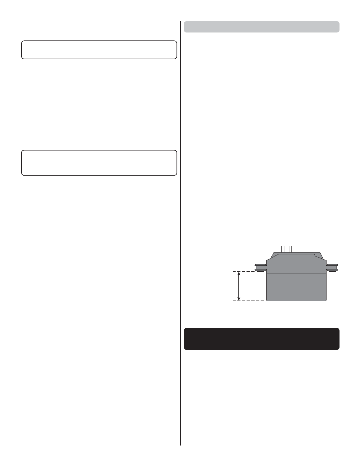
NOTE:
The elevator
servos must
measure no
more than 11/16"
[18mm] from
the bottom up
to the mounting
grommets in order to fi t in the horizontal stabilizers. Taller
servos will require shimming to fi t.
ADHESIVES, HARDWARE AND
OTHER ACCESSORIES
Other than common hobby tools here is a list of the rest of
the items required:
❍ 1/2 oz. [15g] Thin Pro CA (GPMR6001)
❍ 1/2 oz. [15g] Medium Pro CA+ (GPMR6007)
❍ 2 oz. [57g] spray CA activator (GPMR6035)
❍ Threadlocker thread locking cement (GPMR6060)
❍ 2-1/2" spinner (GPMQ4770)
❍ 8mm Propeller Reamer (for O.S. engines or RimFire
1.20 brushless motor) (GPMQ5007)
❍ Drills bits: 1/16" [1.6mm], 3/32" [2.4mm], 1/8" [3.2mm],
7/32" [5.6mm], 7/64" [2.8mm]
4
Page 5
A Robart Super Stand II (ROBP1402) is also indispensable
for working on your Sequence 1.20.
Following are the MonoKote colors used on the Sequence
1.20 should repairs or patches ever be required.
White (TOPQ0204) Sky Blue (TOPQ0206)
Orange (TOPQ0202) Sapphire Blue (TOPQ0226)
Pink (TOPQ0215) Matte Dove Gray (TOPQ0511)
KIT INSPECTION
Before starting to build, take an inventory of this kit to make
sure it is complete, and inspect the parts to make sure they
are of acceptable quality. If any parts are missing or are not
of acceptable quality, or if you need assistance with assembly,
contact Product Support. When reporting defective or missing
parts, use the part names exactly as they are written in the
Kit Contents list.
Great Planes Product Support
3002 N Apollo Drive, Suite 1 Ph: (217) 398-8970, ext. 5
Champaign, IL 61822 Fax: (217) 398-7721
E-mail: airsupport@greatplanes.com
ORDERING REPLACEMENT PARTS
Replacement parts for the Great Planes Sequence 1.20 ARF
are available using the order numbers in the Replacement
Parts List that follows. The fastest, most economical service
can be provided by your hobby dealer or mail-order company.
To locate a hobby dealer, visit the Great Planes web site at
greatplanes.com. Choose “Where to Buy” at the upper right
side of the page. Follow the instructions provided on the page
to locate a U.S., Canadian or International dealer.
Parts may also be ordered directly from Hobby Services by
calling (217) 398-0007, or via facsimile at (217) 398-7721, but
full retail prices and shipping and handling charges will apply.
Illinois and Nevada residents will also be charged sales tax. If
ordering via fax, include a Visa® or MasterCard® number and
expiration date for payment.
Mail parts orders Hobby Services
and payments by 3002 N Apollo Drive, Suite 1
personal check to: Champaign IL 61822
Be certain to specify the order number exactly as listed in the
Replacement Parts List. Payment by credit card or personal
check only; no C.O.D.
If additional assistance is required for any reason contact
Product Support by e-mail at productsupport@greatplanes.
com, or by telephone at (217) 398-8970.
REPLACEMENT PARTS LIST
Order No. Description
GPMA4370
GPMA4371
GPMA4372
GPMA4373
GPMA4374
GPMA4375
GPMA4376
FUSELAGE
WING
STABLIZER
RUDDER
CANOPY/HATCH
COWL
LANDING GEAR
Order No. Description
GPMA4377
GPMA4378
GPMA4379
GPMA4380
GPMA4381
GPMA4382
WHEEL PANTS
WING TUBE
STABILIZER TUBE
DECALS
WING BOLTS (2)
MOTOR MOUNT
BOX PARTS SET
2 2
4
8
5
6
7
12
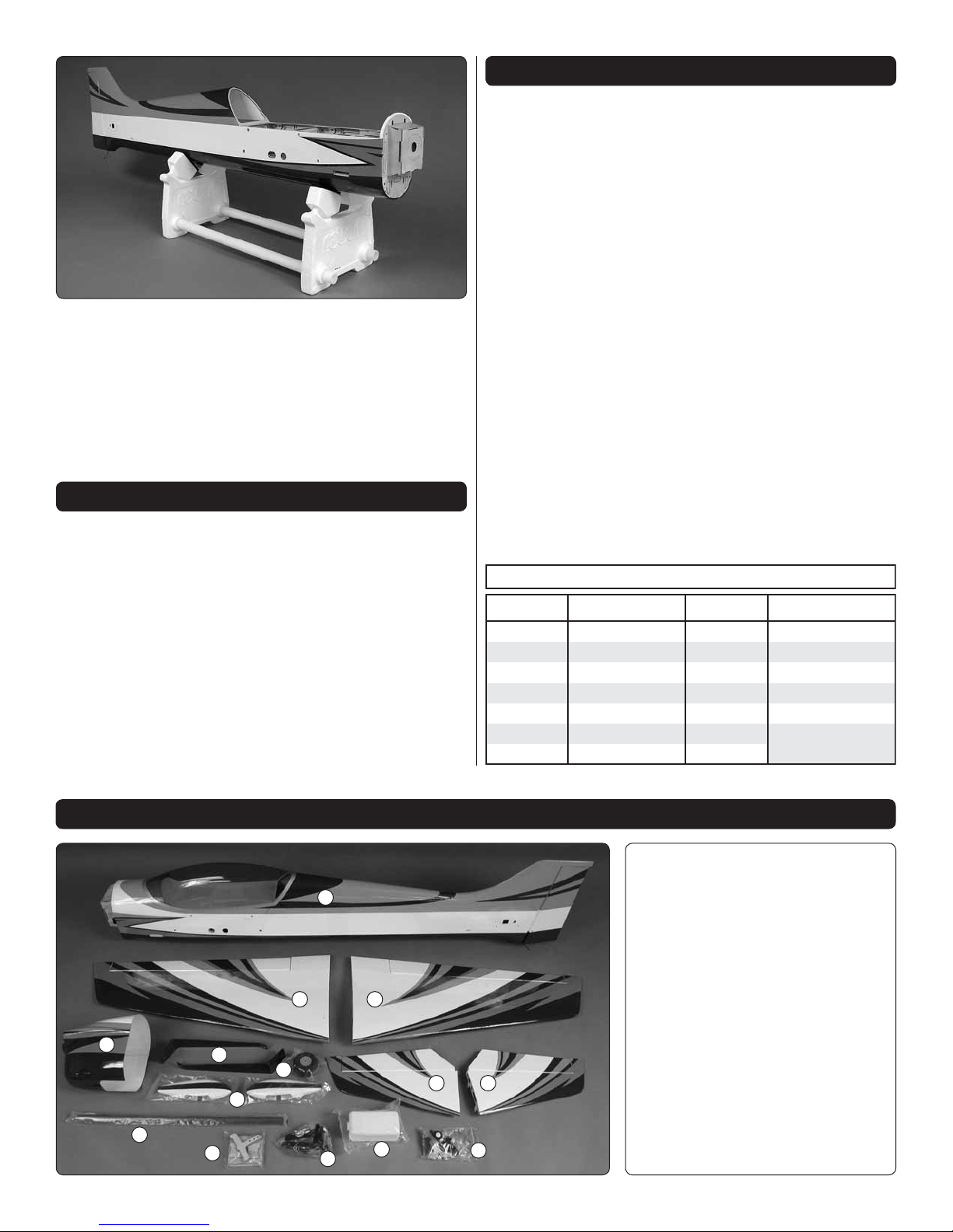
KIT CONTENTS
Kit Contents
1.
1
33
11
10
9
5
Fuselage
2.
Wing Halves
3.
Horizontal Stab Halves
4.
Cowl
5.
Main Landing Gear
6.
Main Wheels
7.
Wheel Pants
8.
Wing Tube
9.
Tailwheel Hardware
10.
Fuel Tank
11.
Glow Engine Mount
12.
ESC Mount Set
Page 6
ASSEMBLE THE WINGS
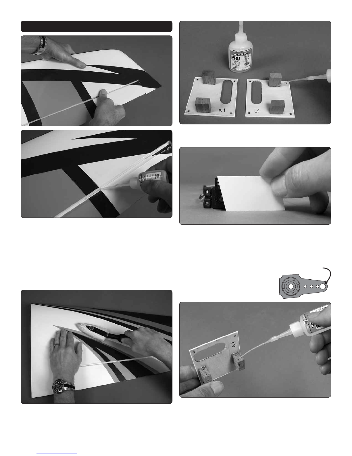
4. Use thin CA followed by a small fi llet of medium CA to
❏
reinforce the servo mounting blocks to the hatch covers.
1. Pull hard on the ailerons to test the hinges. Inspect the
❏
hinges to be sure enough glue has been used. Add a few
drops of thin CA to any hinges that look dry. Note: CA “fogging”
deposited on the covering can be cleaned with CA debonder.
2. Remove the aileron hatch covers and use naphtha
❏
(lighter fl uid) or commercially-available sticker removal
fl uid to wipe away any glue left from the tape that held on
the hatches.
5.
With the servos plugged in and the radio turned on, use
❏
the plastic servo arm gauge to fi nd the servo arms that will
align with the gauge as shown. (This will allow the servo arms
to be perpendicular to the pushrods.) Cut the other arms off.
6.
If using the included Great
❏
Planes 4-40 ball links, enlarge the
holes in the servo arms with a 7/64"
or 1/8" [2.8mm or 3.2mm] drill.
7/64" or 1/8"
[2.8mm–3.2mm]
3. Refer to the “How to Tighten Covering on ARF Models”
❏
sheet and remove wrinkles and bond the covering to the
wings. You can go over the whole model now, or just start
with the wings and get to the rest of the model later.
7. Temporarily mount the aileron servos to the mounting
❏
blocks by drilling 1/16" [1.6mm] holes for the screws.
Remove the screws and servos. Use a few drops of thin
CA to harden the screw holes. Allow the CA to harden before
remounting the servos.
6
Page 7
NOTE: Every time wood screws are used throughout
the rest of assembly always perform this procedure of
installing and removing the screws, then hardening the
holes with thin CA.
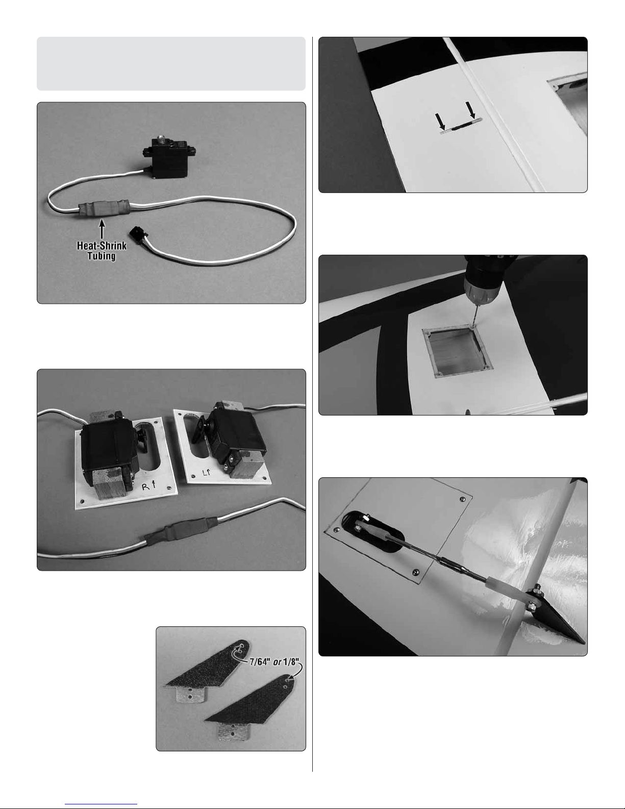
8. Add a 6" [150mm] servo extension to each aileron
❏
servo. Secure the connections with 1-1/2" [40mm] pieces of
the included heat shrink tubing as shown. Use a heat gun to
shrink the tubing.
11. Cut and remove the covering from around the base
❏
of the horns.
12. Securely glue the horns in to position with CA.
❏
9. Mount the servos to the hatches—be certain the servo
❏
arm screws are in place. If you used metal-gear servos, use
a small drop of threadlocker on the threads.
10.
❏
Same as was done for the
4-40 ball links, enlarge
Roughen the tabs
on two of the included,
fi berglass control horns.
servo arms, if using the
included Great Planes
the holes. Without any
glue, test fi t the horns
into the slots—be certain
the horns fi t all the way
down and make any adjustments for a proper fi t
.
13. Drill out the screw holes in the hatch cover frame with
❏
a 1/16" [1.6mm] drill.
Refer to this photo while hooking up the ailerons:
14. Guide the aileron servo wires out the end of the wing
❏
and mount the hatch covers with four #2 x 3/8" [9.5mm]
button-head screws—do not use a ball-end hex wrench.
Use a quality, machine-ground hex driver. If you don’t have
a good hex driver you could replace the included buttonheat screws with Phillips screws and washers (not included)
instead. Don’t forget to temporarily remove the hatch covers,
harden the screw holes with thin CA and allow to harden
before remounting the hatches.
7
Page 8
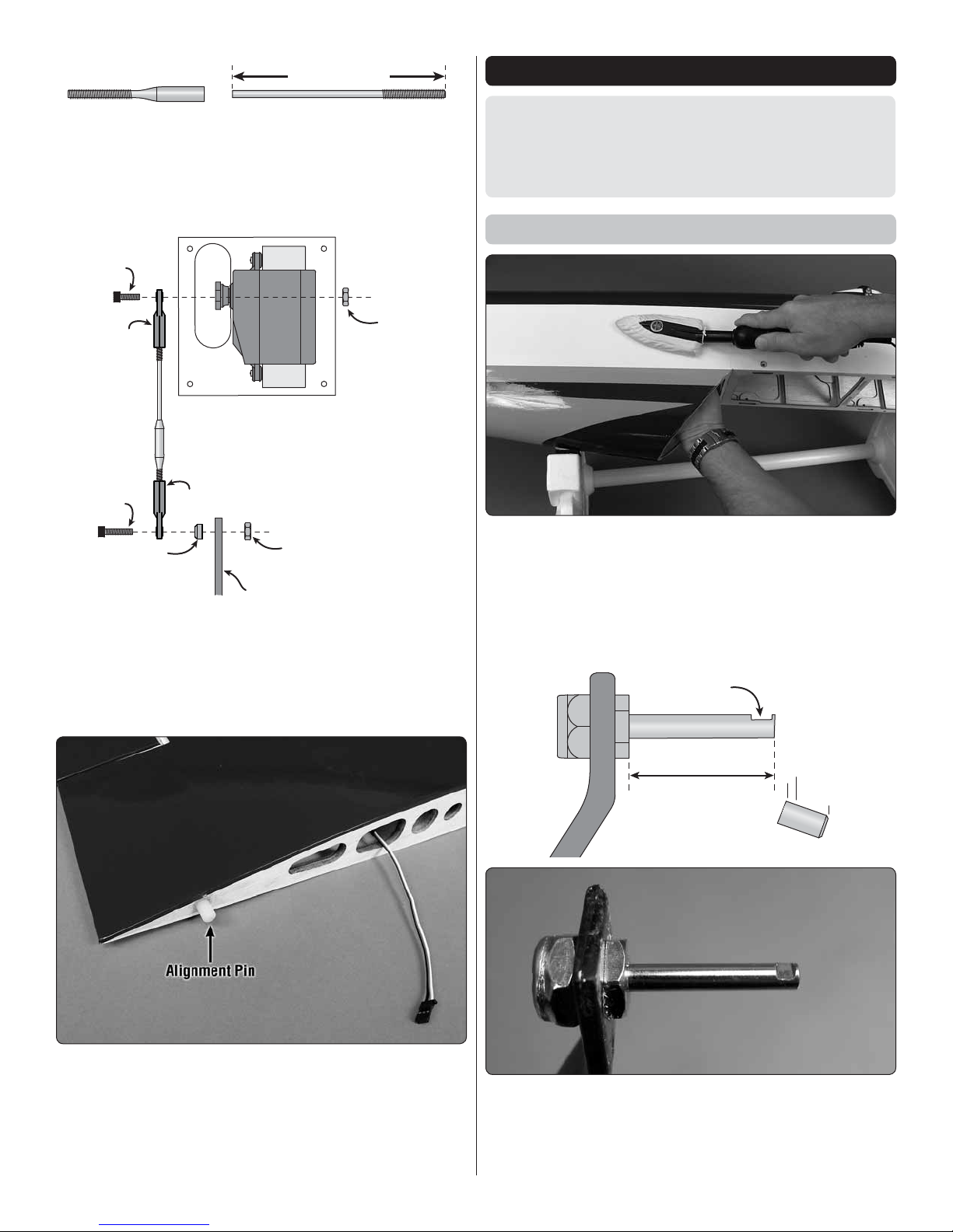
Threaded Coupler
4-40 Pushrod
2-1/4" [57mm]
15. Make the aileron pushrod from a 4-40 x 4-1/2" [115mm]
4-40x 3/8"
SHCS
4-40x 1/2"
SHCS
4-40 Ball Link
Aileron Horn
4-40 Nut
(Use threadlock)
4-40 Nut
(Use threadlock)
4-40 Ball Link
Stand-Off
(optional)
Flat spot
1" [25mm]
❏
pushrod cut to a length of 2-1/4" [57mm]. Clean the pushrod
with denatured alcohol, scuff the end with sandpaper, then
silver solder on a 4-40 threaded coupler.
ASSEMBLE THE FUSELAGE
CAUTION: The turtledeck and fuselage bottom of the
Sequence 1.20 are made from balsa-covered foam.
Some solvents and adhesives will attack the foam, so use
care—especially when using CA which will defi nitely “eat”
into the foam.
Mount the Landing Gear
❏ 16. Connect the aileron horn to the servo arm with the
hardware shown in the illustration—the stand-off on the
aileron horn is optional and not used with the servos shown,
but if your servo spacing is different the standoffs may be
used to keep the pushrod perpendicular to the aileron horn.
Be sure to use threadlocker on the nuts.
1. If you haven’t yet done so, use a covering iron with a
❏
cover sock to go over the fuselage to remove any wrinkles
and bond the covering to the airframe—remember to support
the inside of the sheeting where possible.
2. Test-fi t the main landing gear legs in the fuselage to
❏
distinguish the left from the right and mark them as such.
17. Glue a large alignment pin into the end of each wing.
❏
3. Mount 5/32" [4mm] axles to the main landing gear with
❏
the large lock nuts and threadlocker. Use a rotary tool with a
fi ber-reinforced cutoff wheel to accurately cut the axles to a
length of 1" [25mm], as shown in the illustration. Grind or fi le
a fl at spot on the end of both axles.
8
Page 9
Fiberglass
Wheel Pant
4-40x3/8" [10mm] Phillips
and #4 Flat Washers
5-32" [4mm]
Wheel Collar
#6 Washers
(as spacers) 6-32" Set Screw
4. Mount the wheels and wheel pants as shown—don’t
Vertical Tick Marks
Horizontal
Tick Marks
Angled
Tick Marks
Angled
Tick Marks
❏
forget to use threadlocker on all the screws.
Prepare the Fuselage for Mounting
the Engine (or Electric Motor)
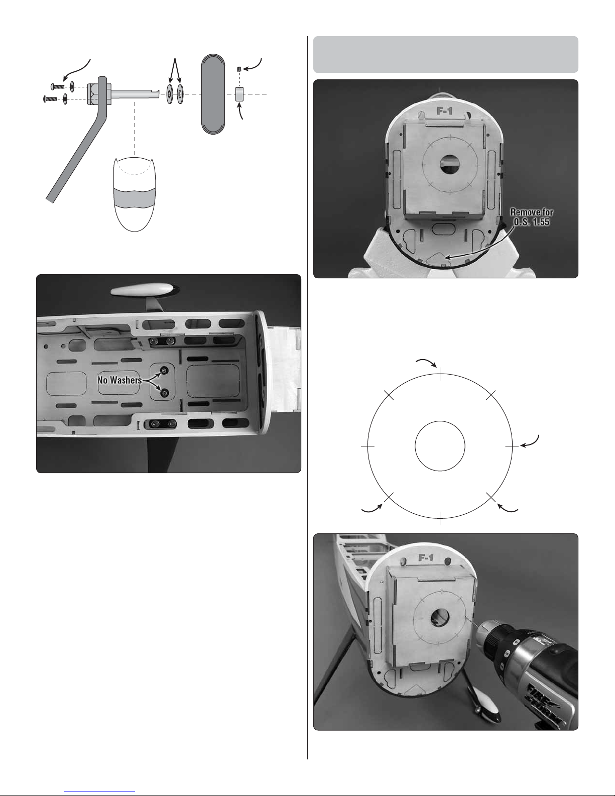
1. If using the O.S. 1.55 FS-a, remove the bottom cutout
❏
for the muffl er. If using a brushless electric motor, remove all
the other cutouts instead. Use epoxy to seal the MonoKote
around F-1, the seams around the cutouts not removed and
the edges of the cutouts you did remove.
5. Mount the main landing gear in the fuselage with
❏
#8 x 1/2" [13mm] SHCS (socket-head cap screws), #8
lock washers and fl at washers—note that the inner screw
on each gear leg uses no washers so the heads will not
protrude too much above the fuel tank/battery plate. As you
have been doing all along, be certain to use threadlocker on
all the screws.
6. Mount the tail wheel with a 3/32" [2.4mm] wheel collar
❏
and a 4-40 set screw and threadlocker.
2. If mounting a glow engine drill 1/16" [1.6mm] pilot
❏
holes through the fi rewall at the four horizontal and vertical
9
Page 10

tick marks. If mounting the Great Planes Brushless Motor
Mount for Large Motors drill the holes through the fi rewall
at the four angled tick marks. If mounting the optional wood
motor mount box, refer to the instructions on page 28 and
assemble/mount the box as illustrated.
3. Enlarge the holes with a 7/32" [5.6mm] drill to
❏
accommodate the 8-32 blind nuts. Draw the blind nuts into
the back of the fi rewall with a #8 SHCS (socket-head cap
screw) and washers.
Mount a Glow Engine
Refer to this photo for the following two steps.
1. Temporarily mount the included engine mount to the
❏
fi rewall with four 8-32 x 1" [25mm] SHCS, #8 lock washers
and fl at washers. Clamp your engine to the mount so the
drive washer will be 6-7/16" [164mm] from the fi rewall.
2. Mark the engine mounting bolt holes with a Great
❏
Planes Dead Center Hole Locator (GPMR8130).
4. If you will be mounting the cowl with the optional cowl
❏
ring, drill 1/8" [3.2mm] holes 3/8" [9.5mm] deep into the
fuselage sides through the two laser-cut holes in F-1. (If
you’re not certain how you will mount the cowl, read ahead
about what’s involved to help you decide.)
If mounting an electric brushless motor skip ahead to
“Mount an Electric Motor” on page 13.
3. Take the mount off the fi rewall and drill #29 (or 9/64"
❏
[3.6mm]) holes at the marks. Tap 8-32 threads into the
holes—a variable speed hand drill makes tapping the
threads fast and easy!
4. Fasten the engine mount back onto the fi rewall and bolt
❏
the engine to the mount with four 8-32 x 1" [25mm] SHCS
and #8 lock washers.
10
Page 11

Hook Up the Throttle
“Hook” side
11" [280mm]
“Loop” side
9" [230mm]
Overlap
5" [130mm]
Velcro Fuel Tank Strap
1. Refer to following photos to see which of the two throttle
❏
servo mounting locations will work best for your engine. Cut
the side or bottom servo mount hole from the location you
will use.
2. Connect a 12" [305mm] servo extension to your throttle
❏
servo and secure the connection with another piece of shrink
tubing.
Install the Fuel Tank
1. Prepare the stopper assembly as shown. Insert the
❏
stopper into the tank and tighten the screw.
3. Mount the throttle servo and hook up the throttle using
❏
the hardware shown in the photo. (It’s not necessary to
mount the muffl er yet, but it’s shown in the photo so you can
see how it fi ts and where to position the exhaust).
2. Make the fuel tank strap from the included Velcro strip
❏
as shown.
3. Install the strap in the fuselage in the location you will
❏
be mounting the tank—it may be necessary to temporarily
punch out one of the lightening holes to install the strap, then
glue the piece back in.
11
Page 12

Mount an Electric Motor
This is a SERIES battery adapter
that connects two batteries in series.
(3-Cell) 3200 mAh
(2-Cell) 3200 mAh
11.1V
7. 4 V
These are two 3200mAh batteries (one 11.1V and the
other 7.4V). When joined in SERIES, the result will be
a 18.5V, 3200 mAh battery.
This is a PARALLEL battery adapter that
connects two batteries in parallel.
(3-Cell) 1500 mAh
(3-Cell) 1500 mAh
11.1V
11.1V
These two 1500mAh batteries (both 11.1V) are being
joined in PARALLEL. The result will be one 11.1V,
3000mAh battery.
Before mounting the motor and setting up the ESC and
battery, read the following important battery precautions:
IMPORTANT: If using multiple battery packs that are connected
with an adapter, never charge the batteries together through
the adapter. Always charge each battery pack separately.
Charge the batteries, then read the following precautions on
how to connect multiple packs for fl ying the model:
Battery Precautions:
There are two ways to connect multiple battery packs: In
Series and in Parallel.
4. Mount the fuel tank with a piece of 1/4" [6.4mm] R/C
❏
foam underneath and securely tighten the strap.
5. Connect the fuel lines (not included) to the engine. A
❏
plastic fuel line plug is included for plugging the fi ll line after
fueling.
Proceed to “CUT THE COWL” on page 16.
1. Connecting batteries in “Series” means to connect the
+’s to the –’s and the –’s to the +’s. This combines the
battery’s Voltages, but the capacity remains the same.
2. Connecting batteries in “Parallel” means to connect
the +’s to the +’s and the -’s to the -’s. This combines the
battery’s capacities, but the Voltage remains the same.
12
Page 13

PARALLEL
adapter
(2-Cell)
(3-Cell)
11.1V
7. 4 V
NEVER connect battery packs with different Voltages in
(3-Cell) 3200mAh
11.1V
(3-Cell) 1250mAh
11.1V
SERIES
adapter
Parallel– only combine in Series. Otherwise, the batteries
will try to “equalize” with the larger one trying to “charge”
the smaller one, thus causing heat and likely a fi re.
from the collar on the end of the RimFire 1.20 motor shaft.
Then, reinstall them with threadlocker and securely retighten.
Refer to this photo while mounting the motor and ESC.
3. Mount the motor to the mount. Adjust the mount and
❏
tighten the bolts so the base of the prop adapter will be 6-3/8"
[162mm] from the fi rewall.
Also NEVER connect battery packs with different capacities
in Series or in Parallel.
1. The Great Planes Large Brushless Motor Mount comes
❏
with Phillips motor mounting screws and thin washers, but
some modelers prefer socket-head cap screws and regular,
thicker washers. If so, substitute the Phillips screws with
3x8mm screws (DTXC8640) and 3mm or #4 washers.
2. Use a 2.0mm hex wrench to remove the set screws
❏
4. If using the Great Planes ElectriFly 80A ESC, install
❏
Great Planes 6mm male/4mm female bullet adapters
(GPMM3119) on the motor wires, or remove the 6mm female
bullet connectors from the ESC and solder on 4mm female
bullet connectors (GPMM3115) instead.
5. If you soldered on 4mm connectors, cover the
❏
connectors with 3/16" [5mm] heat shrink tubing (GPMM1056).
6. Assemble and mount the plywood ESC mount to the
❏
motor mount with four 4-40 x 1/2" [13mm] SHCS, #4 fl at
washers and 4-40 nuts with threadlocker. Mount the motor
mount with the motor to the fi rewall with four 8-32 x 1/2" [13mm]
13
Page 14

SHCS, #8 lock washers and fl at washers and threadlocker.
7. Before mounting the ESC consider the options for
❏
connecting the battery. First, the wires coming from the ESC
are probably not long enough to reach the battery, so an
extension of some sort may have to be made. And if using two
3S LiPo packs connected in series (as illustrated here in the
manual), a Series Deans Ultra 2 to 1 Adapter (GPMM3143)
will also be required. (If using a single 6S battery pack no
adapter will be required.)
The easiest way to get the ESC wires to reach the battery is to
make a plug-in extension with a Deans connector on both ends.
How to Make an Externally-Accessible Arming Plug:
A.
First, you’ll need a
❏
short metal tab to bridge the
tabs across a Deans male
Ultra Plug. A tab extracted
from another male or female
plug works perfectly for this.
B. Cut the tab to length and make a 90° bend on one
❏
end. Solder the tab across the tabs on the plug. Hint: Plug
the arming plug into a female plug to serve as a heat sink
and to make it easier to hold in a vice for soldering.
C. Trim the edges around
❏
the Deans plug as shown.
Glue together the plastic
pieces of the frame for the
plug and test-fi t the plug
into the frame. Make any
adjustments necessary and
glue the assembly together
with CA.
Or, additional wire could simply be soldered directly onto the
ESC.
Finally, an external motor arming plug could be incorporated
with the necessary wiring and receptacle plug soldered to
the ESC. With an arming plug you’ll never have to handle the
airplane while the motor is armed—you can simply install
and connect the battery, mount the canopy hatch, then insert
the arming plug right before you fl y!
D. Apply auto body fi ller to the frame and allow to
❏
partially harden. While the fi ller is still “rubbery” use a
hobby knife to roughly carve it to a teardrop shape.
E. After the body fi ller
❏
has hardened use coarse
sandpaper to sand to the
fi nal profi le.
F.
Use a small rod or
❏
dowel wrapped with mediumgrit sandpaper to cut the
depressions into the sides of
the plug so you can grip it.
G. Prime, sand, then
❏
paint—just about any kind
of paint will work, but we
used enamel spray paint.
14
Page 15

8. Once you’ve made the arming plug, decide which of
❏
the three precut locations in the fuselage side you will use
for mounting a Deans female Ultra Plug to serve as the
receptacle. Solder the plug in-line between one of battery
leads. Solder on any additional wire so the battery and ESC
will reach.
9. Mount the ESC to the ESC mount with three #4 x 1/2"
❏
Phillips screws and #4 fl at washers. After mounting the ESC,
temporarily remove the screws, harden the holes with a few
drops of thin CA, allow to harden, then remount the ESC.
10. If using the arming plug, carefully cut the covering
❏
from the side of the fuselage over the location you will use for
the receptacle. Securely glue the receptacle plug into place
with the plywood doubler.
11. Make battery straps from the included Velcro strips
❏
and guide them in and out of the slots in the battery fl oor
(the rear strap can be reached with your fi ngers under the
rear of the fl oor, but the front strap will require a piece of
wire to pull it up through). Apply strips of the rougher, “hook”
side of Great Planes adhesive Velcro to the battery fl oor and
apply strips of the softer, “loop” side to the batteries. Then
test mount the battery into position just to see how it all fi ts.
15
Page 16

Cut the Cowl
If going electric the cowl probably doesn’t need to be cut—just
skip ahead to “Mount the Cowl” on page 18. But if using a glow
engine the cowl must be cut to fi t over the head and cylinder. If
using an O.S. 1.55FS-a you’re in luck because we’ve provided
a template that can be used as a guide. If installing a different
engine you’ll have to fi gure out where to make the cut yourself.
Some modelers dread this process, but you can make it easier
and achieve great results by proceeding slowly and using
the proper tools. The best way is to cut in small increments,
fi tting and marking the cowl as you go. When you zero-in on
the fi nal shape of the cutout you can position the cowl more
accurately until you can make the fi nal cuts.
template aligns with the bottom of the cowl “cheek” and the
back of the template aligns with the back of the cowl. Use a
fi ne-point felt-tip pen to mark the cutout directly onto the cowl.
With or without a template, the most important thing is to have
the proper tools. It cannot be over emphasized how helpful a
Dremel carbide grout removal bit and a Dremel sanding drum
are for cutting a fi berglass cowl—these can be found at most
hardware and home-improvement stores. Initial cuts go easy,
fast and accurate with the carbide bit. Then, the rough edges
can be smoothed and rounded with the sanding drum. The 1/16"
carbide cutter and 1/4" sanding drum are absolutely a MUST,
but the 1/8" cutter and 1/2" sanding drum come in handy too:
1. The cowl will be easier to start fi tting if you can remove
❏
the head from your 2-stroke engine or remove the valve
cover from your 4-stroke engine. Also leave the muffl er off
the engine for now.
3. If not using the template you will have to determine
❏
where to mark and cut the cowl yourself. Position the cowl as
far over the engine as it will go. Use a lead pencil to mark the
inside of the cowl where it needs to be cut to clear whatever
part of the engine is in the way.
It’s time for cutting. Work in a well-ventilated area and
always wear protective gear including goggles or glasses,
hearing protection and an appropriate breathing fi lteration.
Also do your self a favor and wear a long sleeve shirt to
protect your arms from itchy fi bers that get into the air.
4. Use one of the grout removal bits to start cutting the cowl.
❏
If you’ve marked the cut with the template, cut approximately
1/8" [3mm] inside the lines. If you didn’t use the template, cut
where you made your fi rst marks. Note: The grout removal
bits work best and cut most accurately with the speed of your
rotary tool turned all the way up to full rpm.
2.
If using the O.S. 1.55FS-a, cut the template from the
❏
back of the manual and tape it into the cowl. The top of the
16
Page 17

5. Test fi t the cowl and see where it needs to be cut next.
❏
Mark the inside again if necessary, or switch to a fi ne-point
felt-pen to mark the outside. Remove the cowl and continue
to cut in small increments.
6. Proceed slowly continuing to fi t, mark and cut the cowl
❏
in small increments until you can get it over the engine—
as you really “zero-in” on the cutout, switch to the sanding
drum. When you’re really close, install the spinner back plate
for aligning the front of the cowl. Replace the head or valve
cover onto the engine and continue to adjust the cutout
accordingly. Don’t worry about perfecting the cutout yet—for
now just make the cutout large enough to fi t over the engine
as closely as possible. The fi nal cutout will be perfected after
the cowl has actually been mounted to the fuselage.
17
Page 18

Mount the Cowl
Now that you can get the cowl to fi t over the engine it is
time to determine how the cowl will be mounted. There are
two options: You can use the standard wood screws from
the outside, or use the optional cowl ring. Review the cowl
fi tting process to decide which way you prefer. The cowl ring
requires fabrication of an extended ball-end hex driver, but
the installation is “cleaner” and more durable as there will be
no external screws.
METHOD 1: Mounting the Cowl with the Cowl Ring
Now let’s get back to the cowl ring…
1. Round both ends of the included 1/8" [3.2mm]
❏
hardwood dowel and cut it in half. Glue the dowels into the
cowl ring with 1/4" [6.4mm] protruding from one side—this
will now be the back.
If using the cowl ring, fi rst make an extended hex driver…
A. Use a Dremel with a fi ber-reinforced cutoff wheel to
❏
cut a Great Planes 3/32" Hex driver ball wrench in half. Then
cut a 4" [100mm] section from a 4-40 (.095") pushrod wire.
B. Grind 1/2" [13mm] of the joining ends of the hex
❏
driver so the included brass tube couplers will fi t over the
ends. Then use coarse sandpaper to roughen both ends
of the pushrod wire.
C. Use silver solder with plenty of acid fl ux (that comes
❏
with silver solder) to join the pushrod wire between the
ends of the hexdriver with the brass tubes. The key to a
good soldering job is fi rst to tin the ends of the hex driver
and the pushrod wire—for the hex driver this requires
continually heating the ends and quenching them in fl ux.
After doing this several times the ends of the hex driver will
be thoroughly tinned and ready for joining.
D. After all the soldering is done use a small paper
❏
towel square dampened with acid fl ux to clean residual
fl ux from the wrench. Then follow with steel wool and a
thin coat of oil.
2. Press two 4-40 blind nuts into the front of the top two
❏
holes in the cowl ring.
3. Use the remainder of the 4-40 pushrod you used for
❏
extending the hex driver to pull two 4-40 blind nuts into the
back of the bottom two holes in F-1. Use a 4-40 screw with
washers to draw the blind nuts tightly all the way in. Carefully
add a few drops of thin CA around the blind nuts so they will
not pop out.
18
Page 19

6. Once satisfi ed with the fi t of the cowl ring, re mount it to
❏
the fuselage with the screws.
7. Use coarse sandpaper to roughen the cowl all the way
❏
around the inside so glue will adhere. “Prime” the inside of
the cowl with a few squirts of CA accelerator to keep the CA
from leaking around the cowl ring inadvertently gluing it to
the fuselage.
4. Temporarily fasten the cowl ring to F-1 with four 4-40 x
❏
1/2" [13mm] SHCS and fl at washers—now you can test out
your new extended hex driver!
5. View the cowl ring all the way around the fuselage to
❏
make sure it fi ts well and doesn’t protrude too far over the
edge—it should be pretty much even or extend no more than
approximately 1/64" [.4mm] over the sides of the fuselage.
Where necessary, use a fi ne-point ballpoint pen to mark
the back of the cowl ring where it extends too far over the
fuselage. Remove the cowl ring and sand as necessary.
8. Position the cowl with a #64 rubber band to hold it into
❏
position. Place the fuselage upside-down in your building
stand to get ready for gluing.
9. You’ll need the back plate of the spinner for aligning
❏
the front of the cowl, but it’s best to use the complete
spinner assembly which also usually requires the propeller.
If necessary, trim the propeller cutouts in the spinner cone to
fi t your propeller, and then mount the propeller and spinner.
19
Page 20

10. Medium CA will be used to glue the cowl to the cowl
❏
ring, but you’ll need an extended glue tip in order to reach
down inside. Pipettes and Tefl on tubing may be used, but we
used a length of micro pushrod tubing fi t over a CA tip.
11.
Double-check that the cowl is positioned precisely as
❏
you want it viewing it from all angles to make sure. The rubber
band should securely hold the cowl in position while gluing
.
14. Securely glue the back of the cowl ring with thin CA
❏
and the front of the cowl ring with medium CA.
15. If running a glow engine and the bottom cowl ring
❏
screws are not accessible through the air inlet in the front of
the cowl, cut a rounded slot on both sides of the cowl for the
hex driver. If the bottom two screws are accessible through
the inlet, the slots may not be necessary.
12. Use your extended glue tip to tack-glue the cowl to the
❏
ring with medium CA wherever you can reach—for now, the
cowl only needs to be tack-glued well enough to hold during
removal.
13. Once you’ve got the cowl glued to the cowl ring, use
❏
your extended hex driver to remove the cowl screws. Then,
take off the cowl.
Proceed to “Finish the Cowl” on page 22.
20
Page 21

METHOD 2: Mounting the Cowl with Wood Screws
Hard point
Hard point
In the following steps it may be helpful to have an
assistant drill the holes while you hold the cowl…
A. If using wood screws to fasten the cowl, mark
❏
the screw hole locations over the hard points under the
covering on both sides of the fuselage where shown.
D. Holding the cowl in position, use one of the templates
❏
as a guide to drill the fi rst 3/32" [2.4mm] hole through the
cowl into the fuselage.
E. Enlarge the hole in the cowl only with a 1/8" [3.2mm]
❏
drill. Mount the cowl to the fuselage through that fi rst screw
hole with a #4 x 1/2" [13mm] Phillips screw.
Don’t forget to put the 3/32" [2.4mm] drill bit back into
your drill before drilling the next hole.
B. Make four screw hole templates as shown from thin
❏
plastic or cardstock. Tape the templates to both sides of
the fuselage, aligning the holes in the templates over the
marks made over the hard points.
C. Fit the cowl into position. If you haven’t yet done so,
❏
trim the propeller cutouts in your spinner cone to fi t the
propeller, and then mount the propeller and spinner.
F. Holding the cowl in alignment again, drill the second
❏
3/32" [2.4mm] screw hole. Enlarge that hole in the cowl
only and insert the second screw.
G. Drill the two holes and mount the other side of the
❏
cowl to the fuselage the same way.
H. After all the holes have
❏
been drilled remove the cowl.
Use CA to glue the thin,
plastic bushings to the inside
of the cowl centered over the
holes.
I. Add a few drops of thin
❏
CA to each screw hole in the
fuselage and allow to harden.
21
Page 22

Finish the Cowl
Brass
Cable Swage
4-40x1/2"
SHCS
4-40 Nut
(Use threadlock)
4-40 Ball
Link
Stand-Off
Threaded
Cable Coupler
Great Planes
3" Double-Side
Servo Arm
Hook Up the Rudder and Elevators
1. Same as was done with the ailerons, give a good pull
❏
on the rudder and look at the hinges to make sure they are
all secure. Use thin CA to wet any hinges that look dry.
2. Making sure the trims and sub trims are centered, use
❏
your transmitter to center the rudder servo.
3. Enlarge the second-from-the-outer holes in a Great
❏
Planes 3" [150mm] double-side servo arm (GPMM1165)
with a 7/64" [2.8mm] drill. Mount the servo arm to the servo.
1. If using a glow engine, mount the muffl er and make any
❏
additional cuts necessary—you may have to cut through the
cowl ring, but this won’t weaken the cowl because the ring
will be braced by the fuselage when bolted into position.
2. Make any other cuts/holes necessary for the needle
❏
valve, glow plug and fueling lines.
3. Once all the cowl holes have been cut fi nal-sand the
❏
edges of all cuts with 320-grit or 400-grit sandpaper.
4. If using a glow engine, lightly coat the cowl ring with
❏
thinned epoxy or fuelproof paint.
4. Fit the aft rudder servo rail into position in the fuselage
❏
and adjust it to fi t the rudder servo. Securely glue the rail in
22
Page 23

place. Mount the rudder servo and hook up the rudder using
11/16"
[18mm]
the hardware shown—be certain to use threadlocker on all
the 4-40 nuts and don’t forget to harden the servo mounting
screw holes with thin CA. NOTE: Stand-offs are used under
the ball links on the servo arm, but are not required on the
rudder horn.
5. Pull on the elevators and inspect the hinges. Add thin
❏
CA to any hinges that look dry.
10. Fit both stabilizer halves to the fuselage with the
❏
aluminum joiner tube as you guide the servo wires down
through the fuselage—a long piece of wire with a hook bent
on the end works for pulling the wires.
11. Fasten the stabs to the fuselage with #2 x 3/8" [10mm]
❏
Phillips screws, #2 lock washers and fl at washers. Be certain
to use threadlocker on the threads.
6. If your elevator servos are higher than 11/16" [18mm]
❏
from the bottom of the grommets to the bottom of the servo,
they will need to be shimmed up in order not to interfere with
the sheeting on the top of the horizontal stabilizers.
❏ 7. Cut two more 4-40 pushrods to a length of 2" [50mm]
and solder on the threaded couplers to make the elevator
pushrods. Connect the elevators to the servos with the same
hardware as the ailerons—standoffs were not used under
the ball links on the servos, but were used on the elevator
horns. Be certain to use threadlocker on the nuts
8. Connect a 36" [910mm] servo extension to each
❏
elevator servo wire and secure the connections with 1-1/2"
[40mm] pieces of heat shrink tubing.
.
9. Glue a 1/8" [3.2mm] plastic dowel into each stab half.
❏
23
Page 24

FINAL ASSEMBLY
Set the C.G.
Determine where the model balances before mounting
the receiver battery. Then, mount the battery where
required to achieve the correct C.G.
1. With the exception of the receiver battery, receiver and
❏
on/off switch, the Sequence should otherwise be in readyto-fl y condition with everything else installed (including the
motor battery positioned in the approximate location shown
in previous photos if using an electric motor).
4. Use a Great Planes C.G. Machine or lift the model
❏
with your fi ngers at the balance point. Position the receiver
battery over the fuselage (and/or shift the motor battery) to
get the model to balance.
2. Mount the receiver battery to whichever of the two
❏
included plywood mounting plates fi ts best.
3. If you will be balancing the model with your fi ngers
❏
mark the recommended C.G. location and the forward and
aft C.G. on the top of the wing as shown.
Forward C.G. location 6" [150mm]
Recommended C.G. 6-3/4"
Aft C.G. location 7-1/2" [190mm]
[170mm]
5. Securely mount the receiver battery in the location
❏
required to get the desired C.G.; then, mount the receiver,
switch and an external charge receptacle using the included
plastic mounting plate for the Futaba mini switch and Ernst
charge receptacle. If using a different switch or charge
receptacle, cut the mounting through the side of the fuselage
holes as necessary.
6. Connect the servos to the receiver. Also connect a 6"
❏
[150mm] servo extension into each of the two channels you
will be using in the receiver for the ailerons. Use pieces of the
included small plastic tubing for mounting the Rx antennas.
7. IMPORTANT: Once the receiver battery and the rest of
❏
the radio components have been mounted, recheck the C.G.
Any small adjustments required can be made with Great
Planes stick-on lead weights (GPMQ4485).
24
Page 25

Balance the Model Laterally
These are the recommended control surface throws:
ELEVATOR
3/8"
[10mm]
7°
Up
3/8"
[10mm]
7°
Down
5/8"
[16mm]
11°
Up
5/8"
[16mm]
11°
Down
RUDDER
1-1/4"
[32mm]
13°
Right
1-1/4"
[32mm]
13°
Left
1-3/4"
[44mm]
19°
Right
1-3/4"
[44mm]
19°
Left
AILERONS
1/2"
[13mm]
9°
Up
1/2"
[13mm]
9°
Down
3/4"
[19mm]
13°
Up
3/4"
[19mm]
13°
Down
LOW RATE HIGH RATE
1. With the wing level, lift the model under the tail and by
❏
the propeller shaft. Do this several times.
2. If one wing always drops when you lift the model, it
❏
means that side is heavy. Balance the airplane by adding
weight to the other wing tip. An airplane that has been
laterally balanced will track better in fl ight and maintain
its heading better during maneuvers when the plane is
climbing.
Set the Control Throws
PREFLIGHT
Identify Your Model
Always attach your name, address, telephone number and
AMA number somewhere on or inside your model.
Ground Check
GLOW ENGINES:
Perform your usual checks and tune the engine so it idles
and runs smoothly at full-throttle and transitions reliably
between the two. With the engine running at full-throttle,
have an assistant hold the plane in different orientations
(including nose-up and inverted) to make certain the engine
continues to run smoothly and reliably.
ELECTRIC MOTORS:
Measure and set the throws according to the chart below.
The measurements are taken at the widest part (front-to-
back) of each surface. If the endpoints in your transmitter
programming require more than a 10% to 15% change to
get the required throws, relocate the pushrods on the control
horns or on the servo arms instead. Then, go back and
perfect the throws using the programming in the radio.
Whatever motor, battery, propeller and ESC you are running,
you should fi nd out what current and Watts your setup is
drawing before the fi rst fl ight. Once you have the data you can
compare it to the manufacturer’s specifi cations (or data from
other reliable sources) to make sure everything is operating
within its limits. Noting and recording the current and Watts
(and rpm) your system is making can also be used as a base
for comparison if experimenting with different propellers,
motors or batteries later.
There are a few ways to get this data. One way is to briefl y
run the motor on the ground with a “Watts Up” Watt meter
(RELP0100) connected in-line between the battery and
ESC. The Watt’s Up meter will display the current (Amps),
battery Voltage and Watts. Another way is to use on-board
data logging such as an Eagle Tree Systems ELogger (
ETRP8032) or logging in your ESC. The ELogger stores
data that can be downloaded and viewed on your personal
computer. Additionally, the ELogger can be used in-fl ight to
give you a constant and more accurate picture of what the
system is doing.
Although the static (non-fl ying) data will not be the same as
what it happening in the air, it can still be used as a reference:
For example, testing has shown that the RimFire 1.20 with an
25
Page 26

APC 17 x 8E propeller powered by a 5,000mAh 6S battery
draws about 80A, 1,750 Watts @ 7,500rpm (these are the
initial, static/non-fl ying readings using a fully charged battery).
And in-fl ight data from the ELogger shows that the average
current draw throughout a normal fl ight is about 40A with the
maximum current draw during full-throttle events about 72A.
Once you run your motor on the ground you can compare
your numbers to these as well as the current specifi cations
for the motor. The specifi ed limits for the RimFire 1.20 are
50A constant current and 80A surge current. Because the
setup we are using draws a maximum of 72A in the air, this
is within the specifi ed 50A constant/80A surge limit and is an
acceptable combination as long as full throttle is used only in
short bursts (say, during up-lines or on takeoff).
So, if you are using a RimFire 1.20 and your Watts-Up meter
tells you it is pulling around 80A on the ground, you will know
everything is working normally. However, if for some reason
you are not getting close to those numbers, you will know
something is wrong. It could be a greatly imbalanced propeller,
too large of a propeller, a damaged motor, defective wiring,
etc. Find and correct the problem before fl ying your Sequence.
CAUTION: Never run the motor on the ground for more
than a few seconds. Otherwise, you may overload the
motor, battery or ESC.
4,000mAh (used in fl ight) / 1,000 = 4 Ah / 6 minutes =
.67Amps/minute x 60 minutes = 40A.
The average, in-fl ight current draw was 40 Amps. Even
though we know the motor is drawing 72A during brief, full
throttle bursts, the average current draw over the duration of
the fl ight was only 40A so the motor and ESC are operating
comfortably within their limits.
Another calculation we can make is the percentage of charge
remaining in the battery. If 4,000mAh was used from a 5,000mAh
battery, 20% was remaining. This is generally accepted as a
safe reserve. Flying your LiPos down to no further than 20%
capacity is a good way to extend its life and performance.
Based on this information, you may want to start out setting
your fl ight timer to a conservative four or fi ve minutes. After
the fl ight note the exact fl ight time and the recharge capacity
in your log book. Calculate the percentage of charge that
was left in your battery and adjust your fl ight time accordingly.
Keep in mind that many variables can determine your infl ight current consumption such as how much you used fullthrottle, weather conditions, battery condition, etc. Due to
these variables it is always a good idea to calculate your
maximum fl ight time conservatively.
Range Check
Another smart thing you can do is record the fl ight time and
capacity used from the battery for each fl ight in a log book.
Record the fl ight time (from the timer on your transmitter or
other timer) immediately after each fl ight and record how
much mAh (capacity) went back into the battery read from
the display on your charger. (Number your fl ight packs so you
will be able to correlate each battery to each fl ight.) When
you know the fl ight time and recharge capacity (capacity
used for the fl ight) you can calculate valuable data indicating
how your motor is performing and whether or not your fl ight
time is too long or too short.
For the Sequence 1.20 for example, say we record a 6
minute fl ight. And back in the shop we record that the battery
took 4,000mAh to recharge. With these numbers we can
calculate the average, in-fl ight current draw:
Don’t forget to perform your usual ground range checks as
written in the instruction manual that came with your radio
system to be certain it is operating correctly.
ENGINE / MOTOR
SAFETY PRECAUTIONS
Failure to follow these safety precautions may result
in severe injury to yourself and others.
Keep all engine fuel in a safe place, away from high heat,
sparks or fl ames, as fuel is very fl ammable. Do not smoke
near the engine or fuel; and remember that engine exhaust
gives off a great deal of deadly carbon monoxide. Therefore
do not run the engine in a closed room or garage.
Get help from an experienced pilot when learning to operate
engines.
Use safety glasses when starting or running engines.
Do not run the engine in an area of loose gravel or sand; the
propeller may throw such material in your face or eyes.
Keep your face and body as well as all spectators away from the
plane of rotation of the propeller as you start and run the engine.
Keep these items away from the prop: loose clothing, shirt
sleeves, ties, scarfs, long hair or loose objects such as
pencils or screwdrivers that may fall out of shirt or jacket
pockets into the prop.
Use a “chicken stick” or electric starter to start the engine.
Do not use your fi ngers to fl ip the propeller. Make certain the
glow plug clip or connector is secure so that it will not pop off
or otherwise get into the running propeller.
26
Page 27

Make all engine adjustments from behind the rotating
propeller.
4) I will operate my model using only radio control frequencies
currently allowed by the Federal Communications Commission.
The engine gets hot! Do not touch it during or right after
operation. Make sure fuel lines are in good condition so fuel
will not leak onto a hot engine, causing a fi re.
To stop a glow engine, cut off the fuel supply by closing
off the fuel line or following the engine manufacturer’s
recommendations. Do not use hands, fi ngers or any other
body part to try to stop the engine. To stop a gasoline
powered engine an on/off switch should be connected to
the engine coil. Do not throw anything into the propeller of a
running engine.
AMA SAFETY CODE (excerpts)
Read and abide by the following excerpts from the Academy
of Model Aeronautics Safety Code. For the complete Safety
Code refer to Model Aviation magazine, the AMA web site or
the Code that came with your AMA license.
General
1) I will not fl y my model aircraft in sanctioned events, air shows,
or model fl ying demonstrations until it has been proven to be
airworthy by having been previously, successfully fl ight tested.
2) I will not fl y my model aircraft higher than approximately
400 feet within 3 miles of an airport without notifying the
airport operator. I will give right-of-way and avoid fl ying in the
proximity of full-scale aircraft. Where necessary, an observer
shall be utilized to supervise fl ying to avoid having models fl y
in the proximity of full-scale aircraft.
3) Where established, I will abide by the safety rules for the
fl ying site I use, and I will not willfully and deliberately fl y my
models in a careless, reckless and/or dangerous manner.
5) I will not fl y my model unless it is identifi ed with my name
and address or AMA number, on or in the model. Note: This
does not apply to models while being fl own indoors.
7) I will not operate models with pyrotechnics (any device that
explodes, burns, or propels a projectile of any kind).
Radio Control
1) I will have completed a successful radio equipment ground
check before the fi rst fl ight of a new or repaired model.
2) I will not fl y my model aircraft in the presence of spectators
until I become a qualified flier, unless assisted by an
experienced helper.
3) At all fl ying sites a straight or curved line(s) must be
established in front of which all fl ying takes place with the
other side for spectators. Only personnel involved with fl ying
the aircraft are allowed at or in the front of the fl ight line.
Intentional fl ying behind the fl ight line is prohibited.
5) I will not knowingly operate my model within three miles
of any pre-existing fl ying site except in accordance with
the frequency sharing agreement listed [in the complete
AMA Safety Code].
9) Under no circumstances may a pilot or other person touch
a powered model in fl ight; nor should any part of the model
other than the landing gear, intentionally touch the ground,
except while landing.
CHECK LIST
Perform these last-minute checks to make sure nothing has
been forgotten:
❏ 1. Confi rm that all controls respond in the correct direction
and the throws are set up according to the manual.
❏ 2. Make sure you have checked the C.G. as instructed.
❏ 3. Make sure the lock nuts are present on all the screws
that retain the pushrods to the servo arms and that
the screws that retain the servo arms are in place.
❏ 4. Be certain the battery and receiver are securely
mounted.
❏ 5. If using a radio system on 72 MHz, be certain to extend
the receiver antenna all the way down the antenna
tube in the fuselage.
❏ 6. Use threadlocking compound to secure all critical
fasteners including any servo screws that go into a
metal output shaft.
❏ 7. Add a drop of oil to the axles so the wheels will turn
freely.
❏ 8. Make sure all hinges are securely glued in place.
❏ 9. Reinforce holes for wood screws with thin CA where
appropriate.
❏ 10. Where appropriate, secure connections between servo
wires and Y-connectors or servo extensions, and the
connection between your battery pack and the on/off
switch with vinyl tape, heat shrink tubing or special
clips suitable for that purpose.
❏ 11. Make sure the fuel lines are connected and are not
kinked.
❏ 12. Balance the propellers (and spare propellers).
❏ 13. Place your name, address, AMA number and telephone
number on or inside your model.
❏ 14. Cycle your receiver battery pack (if necessary) and
make sure it is fully charged.
❏ 15. Range check your radio when you get to the fl ying
fi eld.
27
Page 28

FLYING
There are no particular fl ight characteristics about the
Sequence 1.20 that you need to be made aware of ahead of
time. The Sequence is a well-balanced, neutral fl ying plane
that will go wherever you point it. Simply fl y the Sequence
within your capabilities and take it easy for the fi rst couple of
fl ights to give your self time to become acclimated to it.
Have a ball!
But always stay in control
and fl y in a safe manner.
GOOD LUCK AND GREAT FLYING!
OPTIONAL WOOD/FRP
EP MOTOR MOUNT BOX
The wood/FRP (fi ber-reinforced plastic) motor mount box
may be used to “front-mount” a RimFire 1.20 brushless
motor (or other outrunners), or a geared inrunner.
2. Glue both backplate doublers to one side of the tabbed
backplate.
ITEMS REQUIRED:
❍ (4) M3 x 8 motor mounting screws for RimFire 1.20 or
suitable mounting screws for your motor
❍ (4ea) 4-40 blind nuts, 4-40 x 1/2" screws, #4 fl at washers
and lock washers
❍ Great Planes 8mm to 3/8-24 thread propeller adapter (for
RimFire 1.20, GPMQ4971)
1. Use medium-grit sandpaper to roughen both sides of the
FRP front bulkhead so glue will adhere. Glue the four blind
nut doublers to one side of the bulkhead as shown. Then
press 4-40 blind nuts into the doublers. If using a geared
inrunner that requires additional support, also press four
more 4-40 blind nuts into one side of the rear bulkhead. If
used, the rear motor mount may be custom fi t to your motor
and bolted to the rear bulkhead.
3.
Test fi t the sides, top, bottom, backplate assembly, rear
bulkhead and front bulkhead together—be certain the blind nuts
on the front bulkhead and the blind nuts (if used) on the rear
bulkhead are facing aft and the doublers on the tabbed back
plate are also on the back of the stack. Make any adjustments
necessary, and then securely glue the assembly together.
28
Page 29

4. Glue the front bulkhead doubler and the side doublers
5/16" [8mm]
9/16" [15mm]
1/8" [3.2mm]
to the assembly.
to drill 1/16 " [1.6mm] pilot holes through the FRP motor
mount plate. If using a different motor, mark, then drill holes
to fi t your motor. Hint: For perfection, fasten the template to
the mount with 4-40 screws and nuts.
5. Cut two 1" [25mm] pieces and two 2 " [50mm] pieces from
the included balsa triangle stock. Securely glue the triangle
stock pieces around the inside corners of the back plate.
6. If using a RimFire 1.20, use the included plywood RimFire
1.20 motor mount template (and a drill press if available)
7. Remove the plywood template, then enlarge the pilot holes
as illustrated for the RimFire 1.20.
8. If using an inrunner with a gearbox that requires additional
support, cut a hole in the rear motor mount to fi t to your
motor with whatever shock absorption preferred (usually fuel
tubing).
29
Page 30

9. Mount your motor to the motor mount plate—the RimFire
Cut Out
Drill:
7/32" [5.6mm]
1.20 uses four M3 x 8 screws. If also using the rear mount,
fasten it into the mount assembly with four 4-40 x 3/8 "
screws and washers. Test-mount the plate/motor assembly
to the box with four 4-40 x 3/4" screws, washers and lock
washers. Turn the motor by hand, making sure there is no
interference and everything turns free and smooth. Make
any adjustments necessary. Then, remove the mount plate/
motor assembly from the mounting box.
11. Key the mount tabs on the mounting box into the slots
in the fi rewall and fasten the mount with four 8-32 x 3/4 "
socket-head cap screws, #8 lock washers, fl at washers and
8-32 blind nuts. Mount the motor and ESC to the assembly.
12. Rejoin the assembly manual at Mount an Electric
Motor on page 13. Note: The spinner back plate will have
to be enlarged with a 3/8 " [9.5mm] drill for the Great Planes
propeller adapter.
10. Drill 7/32 " [5.6m] holes through the fi rewall at the four “+”
marks and cut the rest of the way through the four, partiallycut slots for the tabs on the motor mount.
30
Page 31

ENGINE CUTOUT TEMPLATE FOR
O.S. 1.55FS-a
31
Page 32

 Loading...