

Page 1
WARRANTY
Great Planes®Model Manufacturing Co.
guarantees this kit to be free from defects in both material and workmanship at the date of purchase. This
warranty does not cover any component parts damaged by use or modification.In no case shall Great Planes' liability exceed the original cost of
the purchased kit. Further, Great Planes reserves the right to change or modify this warranty without notice.
In that Great Planes has no control over the final assembly or material used for final assembly, no liability shall be assumed nor accepted for any
damage resulting from the use by the user of the final user-assembled product. By the act of using the user-assembled product, the user accepts all
resulting liability.
If the buyer is not prepared to accept the liability associated with the use of this product, the buyer is advised to return this kit immediately
in new and unused condition to the place of purchase.
To make a warranty claim send the defective part or item to Hobby Services at the address below:
Hobby Services
3002 N. Apollo Dr., Suite 1
Champaign, IL 61822
USA
Include a letter stating your name, return shipping address, as much contact information as possible (daytime telephone number, fax number, e-mail
address), a detailed description of the problem and a photocopy of the purchase receipt.Upon receipt of the package the problem will be evaluated as
quickly as possible.
READ THROUGH THIS MANUAL BEFORE ST A RTING
CONSTRUCTION. IT CONTAINS IMPORTANT
INSTRUCTIONS AND WARNINGS CONCERNING
THE ASSEMBLY AND USE OF THIS MODEL.
GPMZ0242 for GPMA1360 V1.0Entire Contents © Copyright 2005
Champaign, IL
(217) 398-8970, Ext. 5
airsupport@greatplanes.com
INSTRUCTION MANUAL
Wingspan: 71 in [1805mm]
Wing Area: 676 sq in [43.6 dm2]
Weight: 10.25 – 12.25 lb [4620 – 5555g]
Wing Loading: 35 – 41 oz/sq ft [106 – 127 g/dm2]
Length: 56 in [1410mm]
Radio: 5 or 6-channel with 7-9 ser vos
Engine: .60 cu in [10cc] two-stroke,
.70 – .91 cu in [11.5 – 15cc] four-stroke
Page 2
INTRODUCTION.....................................................................2
AMA.........................................................................................2
SCALE COMPETITION..........................................................3
SAFETY PRECAUTIONS.......................................................3
DECISIONS YOU MUST MAKE.............................................3
Radio Equipment..............................................................3
Engine Recommendations...............................................4
Optional Retracts..............................................................4
ADDITIONAL ITEMS REQUIRED.........................................4
Required Hardware & Accessories..................................4
Adhesives & Building Supplies........................................4
Covering Tools..................................................................4
Optional Supplies & Tools................................................4
IMPORTANT BUILDING NOTES...........................................4
ORDERING REPLACEMENT PARTS ..................................5
METRIC CONVERSIONS ......................................................5
KIT INSPECTION ...................................................................6
KIT CONTENTS......................................................................6
ASSEMBLE THE AIRPLANE STAND...................................7
ENGINE INSTALLATION .......................................................7
Install the Engine..............................................................7
Install the Throttle Pushrod..............................................7
Install the Fuel Tank..........................................................8
Install the Throttle Servo..................................................9
INST ALL THE COWL...........................................................10
LANDING GEAR INSTALLATION OR NOT.......................11
Flying From Water Only..................................................11
Fixed Landing Gear........................................................11
Retractable Landing Gear..............................................14
INST ALL THE ST ABILIZER.................................................16
INST ALL THE RUDDER.......................................................16
RADIO INSTALLATION........................................................17
FINISH THE WING................................................................18
FINISH THE RADIO INSTALLATION..................................19
FINISH THE FUSELAGE......................................................20
GET THE MODEL READY TO FLY .....................................21
Check the Control Directions.........................................21
Set the Control Throws...................................................21
Balance the Model (C.G.) ..............................................22
Balance the Model Laterally...........................................22
PREFLIGHT..........................................................................22
Identify Y our Model .........................................................22
Charge the Batteries ......................................................22
Balance the Propellers...................................................23
Ground Check ................................................................23
Range Check ..................................................................23
ENGINE SAFETY PRECAUTIONS.....................................23
AMA SAFETY CODE (excerpts)........................................23
General...........................................................................24
Radio Control..................................................................24
CHECK LIST.........................................................................24
FLYING..................................................................................25
Fuel Mixture Adjustments ..............................................25
Taking Off from the Ground ...........................................25
Taking Off from the Water..............................................25
Flight ...............................................................................26
Landing ......................................................................26
The full-size Seawind is manufactured by Seawind/S.N.A.,
Inc. It was designed as the world’s best and fastest 4 or 5
place amphibian. It has a cruising speed of 190+ mph,
allowing pilots to reach their destination quickly and
comfortably. Being able to take-off and land from water or
land opens up many destinations not possible with land
based only planes.
Great Planes has now taken this great flying plane and
developed a .60-size ARF. Now you too can fly from land or
water, opening up new flying sites not available before.
Many hours of development and test flying have gone into
the Great Planes Seawind ARF to create an easy to build
and fly amphibious plane. Whether you’re an experienced
float plane pilot or new to this segment of the hobby, we at
Great Planes think you will be very pleased with the
Seawind ARF.
For the latest technical updates or manual corrections to the
Great Planes Seawind ARF, visit the Great Planes web site
at
www.greatplanes.com
. Open the “Airplane” link, then
select the Seawind ARF. If there is new technical
information or changes to this model a “tech notice”box will
appear in the upper left corner of the page.
We urge you to join the AMA (Academy of Model
Aeronautics) and a local R/C club. The AMA is the
governing body of model aviation and membership is
required to fly at AMA clubs. Though joining the AMA
provides many benefits, one of the primary reasons to join
is liability protection. Coverage is not limited to flying at
contests or on the club field. It even applies to flying at
public demonstrations and air shows.Failure to comply with
the Safety Code (excerpts printed in the back of the
manual) may endanger insurance coverage. Additionally,
training programs and instructors are available at AMA club
sites to help you get started the right way. There are over
2,500 AMA chartered clubs across the countr y.Contact the
AMA at the address or toll-free phone number below:
IMPORTANT!!! Two of the most important things you can
do to preserve the radio controlled aircraft hobby are to
avoid flying near full-scale aircraft and avoid flying near or
over groups of people.
Academy of Model Aeronautics
5151 East Memorial Drive
Muncie, IN 47302-9252
Tele: (800) 435-9262
Fax (765) 741-0057
Or via the Internet at:
http://www.modelaircraft.org
AMA
INTRODUCTIONTABLE OF CONTENTS
2
Page 3

Though the Great Planes Seawind is an ARF and may not
have the same level of detail as an “all-out” scratch-built
competition model, it is a scale model nonetheless and is
therefore eligible to compete in the
Fun Scale
class in AMA
competition (we receive many favorable reports of Great
Planes ARFs in scale competition!).In Fun Scale, the “builder
of the model” rule does not apply.To receive the five points for
scale documentation, the only proof required that a full-size
aircraft of this type in this paint/markings scheme did exist is a
single sheet such as a kit box cover from a plastic model, a
photo, or a profile painting, etc. If the photo is in black and
white other written documentation of color must be provided.
Contact the AMA for a rule book with full details.
1. Your Great Planes Seawind ARF should not be
considered a toy, but rather a sophisticated, working model
that functions very much like a full-size airplane.Because of
its performance capabilities, the Seawind ARF, if not
assembled and operated correctly, could possibly cause
injury to yourself or spectators and damage to property.
2. You must assemble the model according to the
instructions. Do not alter or modify the model, as doing so
may result in an unsafe or unflyable model. In a few cases
the instructions may differ slightly from the photos.In those
instances the written instructions should be considered
as correct.
3.You must take time to build straight, true and strong.
4. You must use an R/C radio system that is in first-class
condition, and a correctly sized engine and components
throughout the building process.
5.You must correctly install all R/C and other components
so that the model operates correctly on the ground and in
the air.
6.You must check the operation of the model before every
flight to insure that all equipment is operating and that the
model has remained structurally sound. Be sure to check
clevises or other connectors often and replace them if they
show any signs of wear or fatigue.
7. If you are not an experienced pilot or have not flown this
type of model before, we recommend that you get the
assistance of an experienced pilot in your R/C club for your
first flights. If you’re not a member of a club, your local
hobby shop has information about clubs in your area whose
membership includes experienced pilots.
8.While this kit has been flight tested to exceed normal use,
if the plane will be used for extremely high-stress flying or if
an engine larger than one in the recommended range is
used, the modeler is responsible for taking steps to
reinforce the high-stress points and/or substituting
hardware more suitable for the increased stress.
9. WARNING: The cowl, canopy, wing tips and fuselage in
this kit are made of fiberglass, the fibers of which may
cause eye, skin and respiratory tract irritation. Never blow
into a part (cowl) to remove fiberglass dust, as the dust will
blow back into your eyes. Always wear safety goggles, a
particle mask and rubber gloves when grinding, drilling and
sanding fiberglass parts. Vacuum the parts and the work
area thoroughly after working with fiberglass parts.
Remember:Take your time and follow the instructions to
end up with a well-built model that is straight and true.
This is a partial list of items required to finish the Seawind
ARF that may require planning or decision making before
starting to build. Order numbers are provided in parentheses.
For the basic setup to fly off of water the Seawind ARF requires:
❏ 5-Channel radio
❏ (3) Micro servos with metal gears S3102 (FUTM0034)
for rudder, throttle and elevator
❏ (4) Standard Ball Bearing servos S9001 (FUTM0075)
for (2) aileron (2) flaps
❏ (1) 12" [300mm] Servo extension (HCAM2711
for Futaba®)
❏ (7) 36" [910mm] Servo extension (HCAM2726
for Futaba)
❏ (2) Y-harness (HCAM2751 for Futaba)
Option 1: If the included fixed landing gear is installed, a
fifth S9001 (FUTM0075) servo and a third Y-harness
(HCAM2751) will be required for the nose steering.
Option 2: If the optional retracts are installed, a 6-channel
radio and a Standard S3003 servo (FUTM0031) to operate
the retract air valve are required.
Radio Equipment
DECISIONS YOU MUST MAKE
We, as the kit manufacturer, provide you with a top
quality, thoroughly tested kit and instructions, but
ultimately the quality and flyability of your finished model
depends on how you build it;therefore, we cannot in any
way guarantee the performance of your completed
model, and no representations are expressed or implied
as to the performance or safety of your completed model.
PRO TECT YOUR MODEL,YOURSELF
& OTHERS...FOLLOW THESE
IMPORTANT SAFETY PRECAUTIONS
SCALE COMPETITION
3
Page 4

If you would prefer to set the Seawind ARF up with
flaperons, a 7-channel radio will be required.
The recommended engine size range for the Seawind ARF is
.60 cu in [10cc] two-stroke, .70 – .91 cu in [11.5 – 15cc] fourstroke. Because of the limited clearance between the engine
and fuselage, a 3-bladed propeller is required. A 3-bladed
spinner is included in the kit.
The Seawind ARF can be built three ways.If it will be flown off
of water, no landing gear is required.If the Seawind ARF will be
flown from land, it comes with fixed landing gear. The third
option is to install retracts.The Robart retracts (ROBQ1622) are
recommended. Along with the retracts you will need the
#188VRX Complete Standard Air Kit (ROBQ2307) and #190
Air Line Quick Disconnect (ROBQ2395). All three options are
covered in the instruction manual.
This is the list of hardware and accessories required to finish the
Seawind ARF. Order numbers are provided in parentheses.
❏ R/C foam rubber (1/4" [6mm] – HCAQ1000)
❏ 3' [900mm] Standard silicone fuel tubing (GPMQ4131)
❏ (1) Aluminum fuel line plug (GPMQ4166)
This is the list of Adhesives and Building Supplies that are
required to finish the Seawind ARF.
❏ 1 oz. [30g] Thin Pro
™
CA (GPMR6002)
❏ Pro 6-minute epoxy (GPMR6045)
❏ Pro 30-minute epoxy (GPMR6047)
❏ Threadlocker thread-locking cement (GPMR6060)
❏ Denatured alcohol (for epoxy clean up)
❏ Drill bits: 1/16" [1.6mm], 5/64" [2mm], 3/32" [2.4mm],
7/64" [2.8mm], 1/8" [3.2mm], 9/64" [3.6mm], 5/32"
[4mm], 11/64" [4.4mm], 3/16" [4.8mm], 13/64" [5.2mm],
7/32" [5.6mm], 15/64 [6mm], 1/4" [6.4mm], 17/64"
[6.7mm], 9/32" [7.1mm]
❏ 8-32 Tap and drill set (GPMR8103)
❏ Tap handle (GPMR8120)
❏ Small metal file
❏ Stick-on segmented lead weights (GPMQ4485)
❏ #1 Hobby knife (HCAR0105)
❏ #11 Blades (5-pack, HCAR0211)
❏ Silicone Sealant
❏ Top Flite
®
MonoKote®sealing iron (TOPR2100)
❏ Top Flite Hot Sock
™
iron cover (TOPR2175)
❏ Top Flite MonoKote trim seal iron (TOPR2200)
❏ Top Flite MonoKote heat gun (TOPR2000)
❏ 21st Century
®
sealing iron (COVR2700)
❏ 21st Century iron cover (COVR2702)
❏ 21st Century trim seal iron (COVR2750)
❏ Coverite
™
Covering Thermometer (COVR2410)
Here is a list of optional tools mentioned in the manual that
will help you build the Seawind ARF.
❏ 4 oz. [113g] Aerosol CA activator (GPMR634)
❏ CA applicator tips (HCAR3780)
❏ CA debonder (GPMR6039)
❏ Epoxy brushes (6, GPMR8060)
❏ Mixing sticks (50, GPMR8055)
❏ Mixing cups (GPMR8056)
❏ Builder’s Triangle Set (HCAR0480)
❏ 36" Metal ruler (HCAR0475)
❏ Curved-tip canopy scissors for trimming plastic
parts (HCAR0667)
❏ Pliers with wire cutter (HCAR0630)
❏ Masking tape (TOPR8018)
❏ Rotary tool such as Dremel
®
❏ Rotary tool reinforced cut-off wheel (GPMR8200)
❏ Servo horn drill (HCAR0698)
❏ Dead Center
™
Engine Mount Hole Locator (GPMR8130)
❏ AccuThrow
™
Deflection Gauge (GPMR2405)
❏ CG Machine
™
(GPMR2400)
❏ Laser incidence meter (GPMR4020)
❏ Precision Magnetic Prop Balancer
™
(TOPQ5700)
• When you see the term
test fit
in the instructions, it
means that you should first position the part on the
assembly without using any glue, then slightly modify or
custom fit
the part as necessar y for the best fit.
• Whenever the term
glue
is written you should rely upon
your experience to decide what type of glue to use.When a
specific type of adhesive works best for that step, the
instructions will make a recommendation.
• Whenever just
epoxy
is specified you may use either
30-minute (or 45-minute) epoxy or 6-minute epoxy. When
30-minute epoxy is specified it is highly recommended that
you use only 30-minute (or 45-minute) epoxy, because you
will need the working time and/or the additional strength.
IMPORTANT BUILDING NOTES
Optional Supplies & Tools
Covering T ools
Adhesives & Building Supplies
Required Hardware & Accessories
ADDITIONAL ITEMS REQUIRED
Optional Retracts
Engine Recommendations
4
Page 5
•
Photos
and
sketches
are placed before the step they
refer to. Frequently you can study photos in following steps
to get another view of the same parts.
• The Great Planes Seawind ARF is factory-covered with
Top Flite MonoKote film. Should repairs ever be required,
MonoKote can be patched with additional MonoKote
purchased separately. MonoKote is packaged in six-foot rolls,
but some hobby shops also sell it by the foot. If only a small
piece of MonoKote is needed for a minor patch, perhaps a
fellow modeler would giv e you some.MonoKote is applied with
a model airplane covering iron, but in an emergency a regular
iron could be used. A roll of MonoKote includes full
instructions for application. Following is the color used on this
model and order number for a six foot roll.
White – TOPQ0204
• The stabilizer and wing incidences and engine thrust
angles have been factory-built into this model. However,
some technically minded modelers may wish to check these
measurements anyway. To view this information visit the
web site at
www.greatplanes.com
and click on “Technical
Data.” Due to manufacturing tolerances which will have little
or no effect on the way your model will fly, please expect
slight deviations between your model and the published
values.
Replacement parts for the Great Planes Seawind ARF are
available using the order numbers in the Replacement Parts
List that follows.The fastest, most economical service can be
provided by your hobby dealer or mail-order company.
To locate a hobby dealer, visit the Hobbico web site at
www.hob bico .com
.Choose “Where to Buy”at the bottom of the
menu on the left side of the page. Follow the instructions
provided on the page to locate a U.S ., Canadian or International
dealer.If a hobby shop is not available, replacement parts may
also be ordered from Tower Hobbies
®
at
www.to werhob bies.com
, or by calling toll free (800) 637-6050.
Parts may also be ordered directly from Hobby Services by
calling (217) 398-0007, or via facsimile at (217) 398-7721,
but full retail prices and shipping and handling charges will
apply. Illinois and Nevada residents will also be charged
sales tax.If ordering via fax, include a Visa®or MasterCard
®
number and expiration date for payment.
Mail parts orders and payments by personal check to:
Hobby Services
3002 N. Apollo Dr ive, Suite 1
Champaign, IL 61822
Be certain to specify the order number exactly as listed in
the Replacement Parts List. Payment by credit card or
personal check only; no C.O.D.
If additional assistance is required for any reason contact
Product Support by e-mail at
productsupport@greatplanes.com
,
or by telephone at (217) 398-8970.
Replacement Parts List
Order Number Description How to Purchase
Missing pieces Contact Product Support
Instruction manual Contact Product Support
Full-size plans Not available
GPMA2510 Wing Set w/o Tips Contact Hobby Supplier
GPMA2511 Wing Tips Contact Hobby Supplier
GPMA2512 Fuselage Contact Hobby Supplier
GPMA2513 Stabilizer w/Elevator Contact Hobby Supplier
GPMA2514 Stab Tube/Rods Contact Hobby Supplier
GPMA2515 Water Rudder w/Post Contact Hobby Supplier
GPMA2516 Rudder Contact Hobby Supplier
GPMA2517 Canopy Contact Hobby Supplier
GPMA2518 Cowl Contact Hobby Supplier
GPMA2519 Landing Gear Contact Hobby Supplier
GPMA2520 Nose Gear Doors Contact Hobby Supplier
GPMA2521 Spinner Contact Hobby Supplier
1" = 25.4mm (conversion factor)
METRIC CONVERSIONS
ORDERING REPLACEMENT PARTS
5
1/64" = .4 mm
1/32" = .8 mm
1/16" = 1.6 mm
3/32" = 2.4 mm
1/8" = 3.2 mm
5/32" = 4.0 mm
3/16" = 4.8 mm
1/4" = 6.4 mm
3/8" = 9.5 mm
1/2" = 12.7 mm
5/8" = 15.9 mm
3/4" = 19.0 mm
1" = 25.4 mm
2" = 50.8 mm
3" = 76.2 mm
6" = 152.4 mm
12" = 304.8 mm
18" = 457.2 mm
21" = 533.4 mm
24" = 609.6 mm
30" = 762.0 mm
36" = 914.4 mm
Page 6
66
KIT INSPECTION
Before starting to build, take an inventory of this kit to make sure it is complete, and inspect the parts to make sure they
are of acceptable quality. If any parts are missing or are not of acceptable quality, or if you need assistance with assembly,
contact Product Support. When reporting defective or missing parts, use the part names exactly as they are written in
the Kit Contents list.
Great Planes Product Support
3002 N. Apollo Dr ive, Suite 1
Champaign, IL 61822
Telephone: (217) 398-8970, ext. 5
Fax:(217) 398-7721
E-mail:
airsupport@greatplanes.com
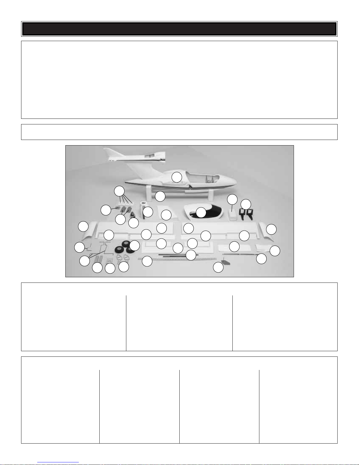
Parts Layout
1. Fuselage
2. Rudder
3. Canopy
4. Fuel Tank
5. Engine Mount
6. Airplane Stand
7. Cowl
8. Spinner
9. Main Fixed LG Mount (2)
10. Nose Gear Mounting Plate
11. Aileron & Flap Servo Covers
12. L&R Wing Tips
13. L&R Ailerons
14. L&R Flaps
15. L&R Wing Panels
16. Nose Gear
17. Main LG
18. Main LG Blocks
19. Throttle Servo Tray
20. L&R Wing Tip Supports
21. Main Wheels (3)
22. L&R Horizontal Stabilizer
23. Elevator
24. Aluminum Wing Joiner
25. Horizontal Stabilizer Tubes (2)
26. Water Rudder
27. Nose Gear Cover
28. Pushrods
29. Throttle Servo Hatch Cover
(8) Clevis
(2) CA Hinge Strip
(6) Large Control Horn
(34) #2 x 3/8" [9.5mm] Philips Screws
(7) 2-56 x 6" [152mm] Pushrod
Threaded One End
(8) Nylon FasLink
(8) 1/4" [6.4mm] Silicone
Clevis Retainer
(2) Screw-Lock Pushrod Connector
(2) 4-40 x 1/4" Socket-Head Cap Screw
(2) Nylon Retainer (for screw-lock
pushrod connector)
(2) #6 Flat Washer
(8) #8 Lock Washer
(8) 8-32 x 1" [25mm] Socket-Head
Cap Screw
(8) #8 SAE Flat Washer Plated
(8) #8 Split Ring Lock Washer Plated
(4) 8-32 Blind Nuts
(1) #4 x 5/8" [16mm] Sheet
Metal Screw
(5) #4 Flat Washer
(8) #2 Flat Washer
(9) 5/32" [4mm] Wheel Collar
(8) 6-32 x 1/8" [3mm] Set Screw
(4) Landing Gear Strap
(2) 6-32 x 3/4" [19mm] Pan Head Screw
(2) 6-32 Hex Nut
(1) 6-32 x 1/4" Socket Head Bolt
(1) Steering Arm
(8) #6 x 1/2" [13mm] Philips Sheet
Metal Screw
(1) 5/32 Nose Gear Bearing
(4) Metal Clevis 2-56 Threaded
(4) 2-56 Hex Nut
(2) Metal Retainer (for screw-lock
pushrod connector)
(1) 1200 x 10 x 2mm Foam Tape
(2) 1/4-20 Thumb screws
(1) Complete Water Bailer
(2) Steel Wing Alignment Pins
(1) Wheel Collar with Wire (for
steering mechanism)
(2) Hardwood Blocks (throttle servo)
(1) Retainer Plate (throttle servo)
(1) 25 x 25 x 0.8mm Double-Sided
Foam Tape (throttle servo)
(2) Threaded Cable Connectors
(2) Steering Cable
(1) 2.5mm Hex Wrench
not used
10 x 10 x 230mm Balsa Sticks
Kit Contents (Not Photographed)
Kit Contents
1
3
28
27
29
11
5
6
2
4
10
12
12
15
15
13
14
13
14
7
9
16
17
18
19
20
24
22
22
23
25
26
21
8
Page 7
❏ 1. Remove the two styrofoam airplane stand ends and the
two 1-5/8" x 27-1/2" [41 x 660mm] plastic tubes. Slide the
tubes into the two ends.
We are going to install the engine in the upright position first
to prevent damaging other components of the plane while
maneuvering the plane around.
❏ 1. Cut the “spreader bar” from the supplied Great Planes
engine mount. Use a hobby knife to remove any flashing left
over from the molding process so that the halves fit
together well.
❏ 2. Temporarily attach the engine mount upright to the
firewall using four 8-32 x 1" [4 x 25.4mm] socket-head cap
screws, four #8 flat washers and four #8 lock washers.
❏ 3.Position the engine on the engine mount so that the front
of the drive washer (or back of the spinner) is 5-1/8" [130mm]
from the firewall.Also make sure the engine is centered on the
engine mount.
❏ 4. Use a Great Planes Dead Center
™
hole locator to mark
on the engine mount the four engine mounting holes.
❏ 5. Remove the engine mount and use a drill press, if you
have one, to drill a 9/64" [3.5mm] hole at each mark,
perpendicular to the engine mount rails. Then, tap all four
holes with an 8-32 [6mm] tap.
❏ 6. Using four 8-32 x 1" [6 x 25.4mm] socket-head cap
screws, four #8 lock washers and four #8 flat washers, install
the engine on the engine mount.
❏ 7. Remove the four 8-32 [4mm] socket-head cap screws
from the engine mount and rotate the mount 180 degrees so
that the engine is mounted inverted. Be sure to use threadlock on the 8-32 [4mm] socket-head cap screws when
reinstalling them.
❏ 1. Inser t the 11-3/4" [298mm] gray outer pushrod tube in
the fuel tank compartment through the formers as shown.
Note the location that the pushrod tube hits the back of the
firewall.This will give you an idea where the pushrod must e xit
the firewall to allow smooth operation.
Install the Throttle Pushrod
Install the Engine
ENGINE INSTALLATION
ASSEMBLE THE AIRPLANE STAND
7
Page 8
❏ 2.Drill a 3/16" [4.8mm] hole through the front of the firewall.
Roughen the outer pushrod with sandpaper. Inser t the outer
pushrod tube through the firewall and the former so that it
protrudes through the first former by approximately 1"
[25.4mm].Trim the excess flush with the front of the firewall.
❏ 3. Install a screw-lock pushrod connector on the throttle
arm and secure it with a nylon keeper.
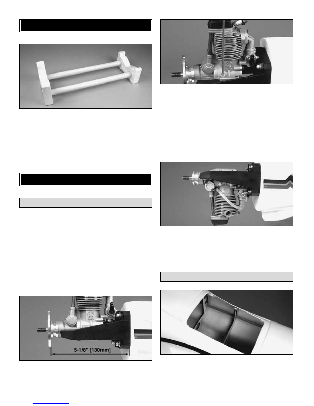
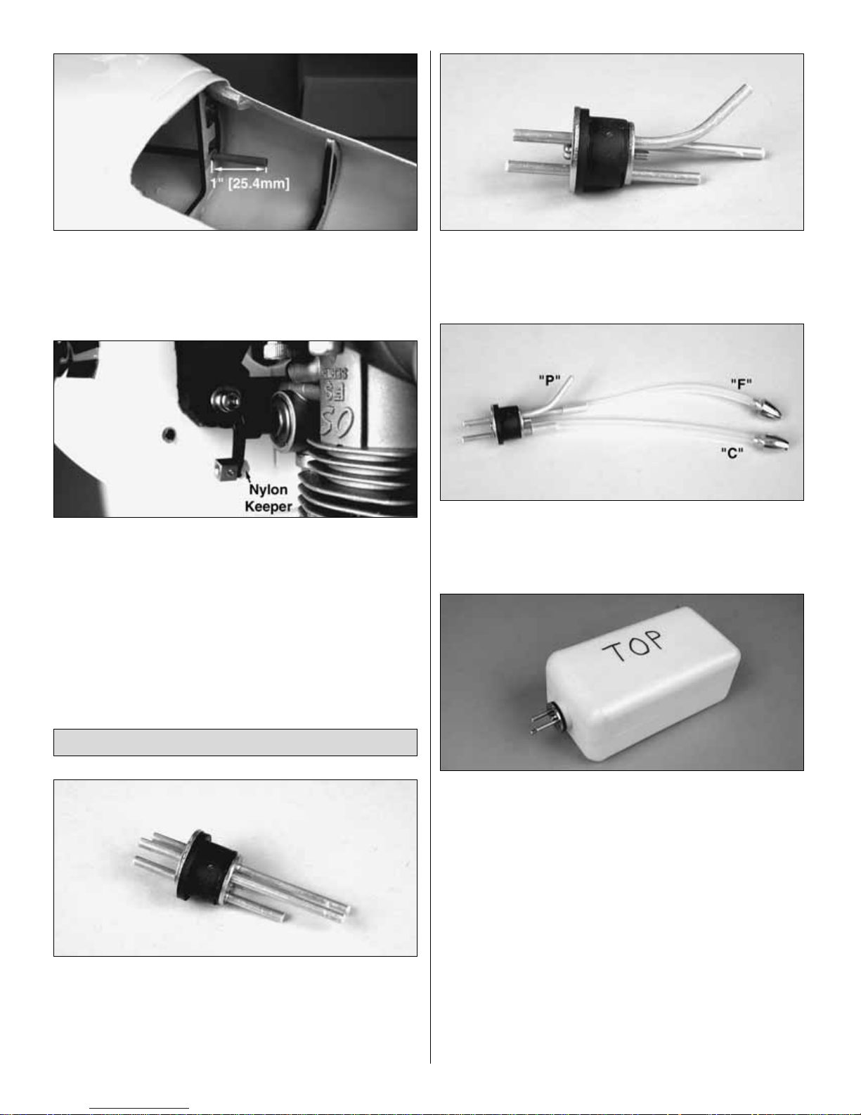
❏ 1.Remove the components from inside the fuel tank.Install
the three aluminum tubes in the fuel tank stopper. You will
need to use a hobby knife to open the third hole in the rubber
stopper.Slide the small metal plate over the tubes and thread
the screw into the plate until it makes contact with the back of
the rubber stopper.Do not tighten the screw.
❏ 2. Carefully bend one of the long tubes so that it will angle
up toward the top of the fuel tank when inserted. Do not kink
the tube. Mark a “P” on the outside of the front plate to
designate pressure.
❏ 3. Install a piece of fuel tubing on each of the other two
tubes. Attach a clunk on the ends of the tubes. Mar k a “C” on
the outside of the front plate by the short tube, designating
carb, and an “F” by the remaining tube, designating fill.
❏ 4. Inser t the tank stopper in the fuel tank. Check that the
two clunks are able to move freely when the stopper is
inserted completely.Then, tighten the screw in the stopper to
seal the fuel tank.Write “top” on the side of the fuel tank where
the pressure tube sticks up.
❏ 5.Install three pieces of fuel line on the three aluminum fuel
tubes in the front of the fuel tank. Inser t the fuel tank into the
fuel tank compartment, routing the fuel line out of the firewall.
Make sure the top of the tank faces upward.
❏ 6. Connect the correct fuel line to the carburetor and the
fuel line plug to the fill line.The pressure line will be connected
to the muffler once the cowl has been installed.
Install the Fuel Tank
8
Page 9
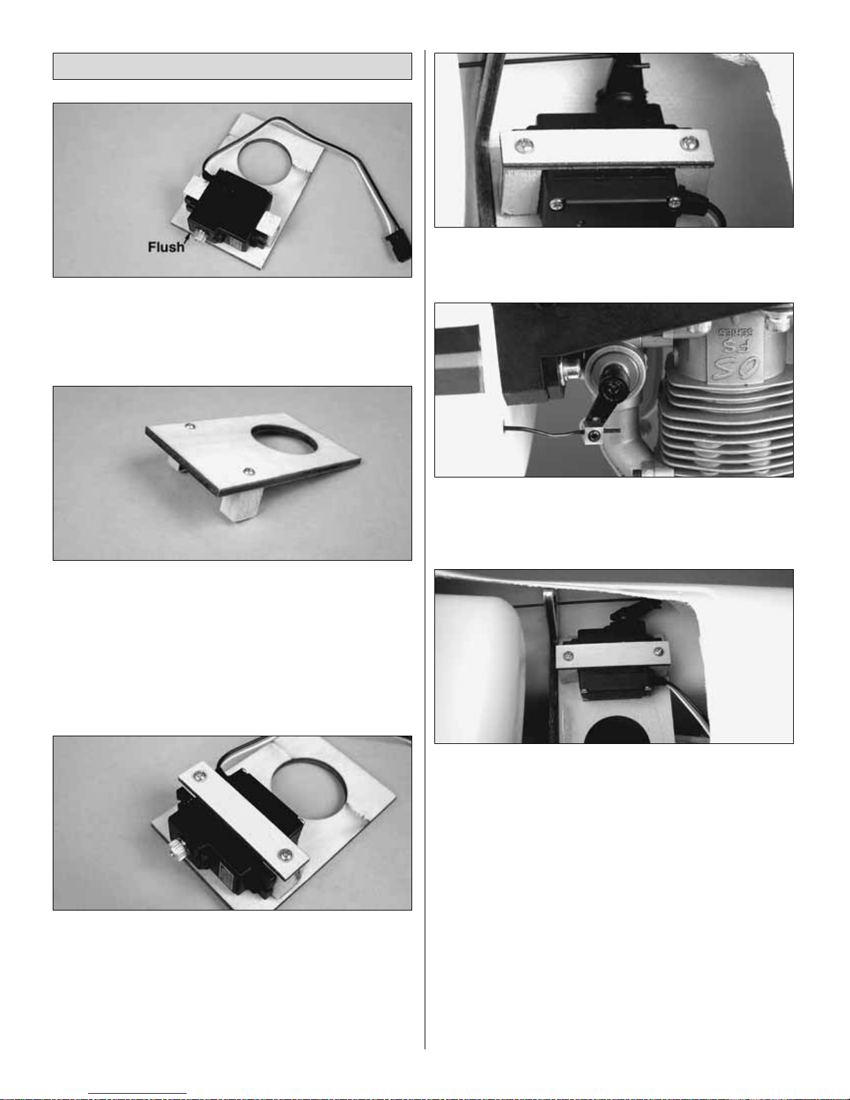
❏ 1. Position the Micro servo with the top of the servo case
flush and centered with the edge of the throttle servo tray. Use
epoxy to glue the two hardwood servo tray blocks on each
side of the servo against the servo mounting flanges.
❏ 2. Once the glue has cured, remove the servo, turn the
servo tray ov er and drill a 1/16" [1.6mm] pilot hole through the
servo tray and into the servo tray blocks, centered in the
blocks.Secure the servo tra y blocks to the servo tray with tw o
#2 x 3/8" [9.5mm] self-tapping screws.
❏ 3. Attach the 1" x 1" [25.4 x 25.4mm] double-sided tape to
the servo tray, between the servo tray blocks.Then attach the
throttle servo to the tape.
❏ 4. Position the plywood servo retainer over the servo and
drill a 1/16" [1.6mm] pilot hole at each end through the retainer
and into the servo tray block.
❏ 5. Connect a 36" [914mm] ser vo extension to the throttle
servo.Tie the string in the fuel tank compartment to the end of
the extension and pull the extension through the tube and into
the fuselage.Tape or heat-shrink the leads together.
❏ 6.Insert the throttle pushrod in the pushrod tube.Insert the
Z-Bend in the throttle servo horn. Position the throttle servo in
the fuel tank compartment.
❏ 7.Use a pliers to bend the throttle pushrod so that it can be
inserted in the screw-lock pushrod connector. Cut off the
excess pushrod and secure the pushrod in the screw-lock
pushrod connector with a 4-40 set screw.
❏ 8. Use epoxy to glue the throttle servo tray in the fuel
tank compartment.
❏ 9. Temporarily plug the throttle servo and receiver battery
into your receiver. Adjust the throttle pushrod so that the
throttle operates correctly. We normally set up our throttle so
that the engine can be stopped by moving a switch, causing
the throttle to close completely.
Install the Throttle Servo
9
Page 10

❏ 1. Use a piece of thin cardboard or plastic to make a
template for the cutout in the cowl for the head of the engine.
Tape the template to the fuselage, accurately indicating the
position of the head.
❏ 2. Carefully remove the engine. Slide the cowl in position
and tape it to the fuselage. Use a felt-tip pen to transfer the
hole in the template onto the cowl.
❏ 3. Remove the cowl and template, and then remount the
engine. Cut out the hole in the cowl, test-fitting it over the
engine as you go.
Hint: Cut the hole in the cowl undersize at first so you can
make adjustments to its position.
❏ 4. Once the cowl is trimmed to fit and positioned over the
engine, install the spinner backplate on the engine.Adjust the
cowl so that the spinner backplate aligns with the front of the
cowl.Tape the cowl in position.
❏ 5. Drill a 1/16" [1.6mm] pilot hole, above and below the air
exit indentation. Increase the hole in the cowl only to 3/32"
[2.4mm]. Secure the cowl to the fuselage with four #2 x 3/8"
[9.5mm] self-tapping screws and #2 flat washers.
❏ 6. Remove the spinner backplate and the cowl. Using the
template method, locate and cut the hole for the needle valv e .
Connect the fuel line to the carburetor. Replace the cowl and
install the muffler.Attach the pressure line to the muffler.
❏ 7.Use a sharp canopy scissors and sanding bar to trim the
throttle servo hatch cover to fit the fuselage.
❏ 8. Note the four wood blocks, in each corner, under the
throttle servo hatch opening.Position the hatch cov er o v er the
opening and drill a 1/16" [1.6mm] pilot hole in each corner.
Remove the hatch cov er and enlarge the holes in the co v er to
3/32" [2.4mm]. Secure the hatch cover to the fuselage with
four 2 x 8mm sheet metal screws and 2mm washers.
❏ 9. Install the spinner backplate and then the propeller on
the engine.Secure the propeller with the prop washer and the
propeller nut included with your engine.
❏ 10. Install the spinner nut included with the Seawind ARF.
Position the spinner over the propeller and use the included
socket-head bolt to attach the spinner to the spinner nut.
Depending on the thickness of the propeller , y ou may need to
cut the socket-head bolt.
INST ALL THE COWL
10
Page 11

If the plane will be flown from water only, the nose gear cover
plate can be permanently glued in the fuselage. If you think
that in the future you may want to install landing gear in the
plane, follow the instructions below, but do not glue the nose
gear cover plate in the fuselage.Instead use clear box tape to
secure the plate in position.
If landing gear will be installed, proceed to
“Fixed Landing
Gear or Retractable Landing Gear.”
❏ 1.Glue the plywood end plate to the nose gear cov er plate.
❏ 2. Use a canopy scissors or a Dremel
®
Rotary Tool and
sandpaper to trim the fiberglass nose gear cover to fit on the
nose gear cover plate and in the nose gear opening.
❏ 3. Once the cover and cover plate fit well in the nose gear
opening, glue the fiberglass cover to the cover plate.Coat the
plywood plate with epoxy, thinned with denatured alcohol, to
prevent the wood from soaking up water.
❏ 4.Use sandpaper to roughen the inside of the nose gear
opening where the cover plate will be glued.Clean the area
with denatured alcohol. Use epoxy to glue the nose gear
cover in the nose gear opening, flush with the bottom of the
fuselage. Note: Glue the cover on with silicone sealant if
you plan to remove it later.
❏ 5. After the epoxy has cured, drill a 3/32" [2.4mm] hole at
the aft edge of the fiberglass cover plate to allow w ater to drain
out of the nose gear opening.
❏ 1. Attach the nylon nose gear bearing to the nose gear
mounting plate using two 6-32 x 1/2" [4 x 12.7mm] machine
screws, two 6-32 [4mm] nuts and #6 washers.
❏ 2. Slide a 5/32" [4mm] wheel collar on the nose gear wire.
Insert the nose gear in the nose gear bearing and install a
second 5/32" [4mm] wheel collar.Secure the wheel collars to
the nose gear wire with a 6-32 [4mm] set screw.
Fixed Landing Gear
Flying From Water Only
LANDING GEAR INSTALLATION
OR NOT
11
Page 12

❏ 3.Drill a 1/16" [1.6mm] hole through the nylon steering arm
5/8" [15.9mm] from the center of the arm. Trim the steering
arm so that only this hole remains.Insert a 5/32" [4mm] wheel
collar in the steering arm and install a 6-32 x 1/4" [4 x 6.4mm]
socket-head cap screw through the steering arm and into the
wheel collar.Slide the steering arm on the nose gear wire.So
that the arm is parallel to the axle of the nose gear, file a flat
spot where the socket-head cap screw tightens on the nose
gear. Apply thread-lock to the socket-head cap screw and
tighten it on the nose gear.
❏ 4. Position the nose gear plate so that the aft edge of the
plate is flush with the aft edge of the nose gear mount in the
fuselage. Mark the four mounting holes and drill a 3/32"
[2.4mm] pilot hole at each mark.Attach the nose gear plate to
the fuselage with four #4 x 1/2" [12.7mm] sheet metal screws.
❏ 5. Drill 1/16" [1.6mm] pilot holes and mount the steering
servo, using the hardware that came with your radio.
❏ 6. Drill a 3/32" [2.4mm] hole through the aft edge of the
nose wheel recess, 1" [25.4mm] from the bottom of the
fuselage.You will need to remove the nose gear to allow room
for the drill.While the nose gear is removed, apply a couple of
drops of thin CA to each of the screw mounting holes to
harden the wood, before remounting the nose gear.
❏ 7. Thread a nylon clevis approximately 14 turns onto the
12" [304.8mm] metal pushrod. Slide a silicone clevis retainer
over the clevis.
❏ 8. Insert the pushrod in the hole at the back of the nose
wheel recess.The pushrod will require some bending so that
the clevis can be attached to the steering arm.
❏ 9.Temporarily connect the steering ser vo to your receiver
and center the servo arm. Position the nose gear wire so that
it is perpendicular to the centerline of the fuselage. Mark the
pushrod where it crosses the mounting holes in the servo
arm. Make a 90° bend at the mark. Attach the pushrod to the
servo arm using a nylon FasLink.Cut the excess pushrod wire
so that it slightly protrudes out of the FasLink.
12
Page 13

❏ 10. Install a 5/32" [4mm] wheel collar and 6-32 [4mm] set
screw on the nose gear wire, followed by one of the foam
wheels and a second wheel collar and set screw.
❏ ❏ 11. Use a sharp hobby knife to trim the covering from
over the main landing gear opening in one of the wing halves .
❏ ❏ 12. Insert the main landing gear wire in the grooved
hardwood landing gear block.Position two nylon landing gear
straps over the landing gear wire and mark the four mounting
hole locations.
❏ ❏ 13. Drill a 1/16" [1.6mm] pilot hole into the landing gear
block at each mark. Secure the landing gear straps to the
block with four #2 x 3/8" [9.5mm] sheet metal screws.
❏ ❏ 14. Position the landing gear block in the metal main
landing gear mount so that the landing gear wire goes through
the mount. Drill a 7/64" [2.7mm] pilot hole at each mounting
hole location and attach the landing gear block to the metal
mount with four #6 x 1/2" [12.7mm] sheet metal screws.
❏ ❏ 15.Insert the landing gear in the wing so that the landing
gear wire is closest to the wheel recess.Mark and drill four 7/64"
[2.7mm] pilot holes, in the mounting holes closest to the landing
gear wire. Secure the landing gear to the wing with four #6 x
1/2" [12.7mm] sheet metal screws in the positions shown.
❏ ❏ 16. Install a 5/32" [4mm] wheel collar and 6-32 [4mm]
set screw on the landing gear wire, followed by one of the
foam wheels and a second wheel collar and set screw.
❏ 17. Go back to step 1 and install the fixed landing gear in
the other wing half.
13
Page 14

❏ 1. Drill 1/16" [1.6mm] pilot holes and mount the steering
servo, using the hardware that came with your radio.
❏ 2. Connect the steering ser vo to your receiver and center
the rudder trims on your transmitter. Install a two arm servo
arm on the steering ser vo so that the arms are perpendicular
to the centerline of the servo.
❏ 3.Install a piece of air line tubing on the retract air tank.Use
silicone adhesive or epoxy to glue the retract air tank in the
formers on the right side of the fuselage.
❏ 4. Drill a hole in the radio tray to fit your fill valve. Attach air
line tubing between the air tank and fill valve.
❏ 5. Attach the control valve to the plywood control valve
mount. Attach the air line tubing to the control valve and glue
the mount to the radio tray.
❏ 6. Install the control valve servo in the radio tray using the
hardware supplied with the servo.
❏ 7. Thread a nylon clevis approximately 14 turns onto the
end of a 6" [152mm] wire pushrod. Install a silicone clevis
retainer on the clevis.Install the clevis on the control valve.
❏ ❏ 8. Use a shar p hobby knife to trim the covering from
over the main landing gear opening in one of the wing halves .
❏ ❏ 9. Install a foam wheel on one of the main retracts
following the retract manufacturer’s instructions. Install the air
Retractable Landing Gear
14
Page 15

line tubing on the main retracts.Position the main retract in the
wing so that the wheel is centered in the wheel well.Use a felttip pen to outline the mounting flanges of the main retracts.
Use a sharp hobby knife to cut and remove balsa sheeting
over the hardwood mounting rails. Reinstall the main retracts
in the wing and secure them to the plywood rails with the
screws included with the main retracts.
❏ ❏ 10.Position the nose gear retract on the landing gear r ail.
❏ ❏ 11. Determine the best location for the air line tubing to
come through the wheel well and drill a hole to route the air
line tubing through. Connect the air line tubing to the retract
and the control valve.
❏ ❏ 12.Mount the nose gear retract in the fuselage with the
screws included with the main retract.
❏ 13. Drill a 1/16" [1.6mm] hole in both of the aft cor ners,
1-1/8" [28.5mm] from the bottom of the fuselage.
❏ ❏ 14. Put a piece of masking tape on the end of one of
the metal cables. Insert the cable in one of the holes. The
masking tape will prevent the cable from pulling through the
hole. Slide a metal furl on the cable inside the fuselage.Then
thread the cable through the bottom hole in the threaded
coupler and then back through the furl. Use a pliers to crimp
the furl on the cable.
❏ ❏ 15.Install a 2-56 nut half-wa y onto the threaded coupler .
Install a silicone clevis retainer on a 2-56 threaded metal
clevis.Install the clevis on the threaded coupler and tighten it
against the 2-56 nut.
❏ ❏ 16. Attach the clevis in the outer hole of the steering
servo arm.
❏ 17. Return to step 14 and repeat the process for the
second steering cable.
❏ 18. Lower the nose gear retract and slide a metal furl on
each of the steering cables. Route the cables through the
attachment arms on the nose gear and back through the furls.
With the steering servo arm centered and the nose gear
straight, pull the cable tight.Then, crimp the two furls on the
cable.Cut off the excess cable.
❏ 19. Install a foam wheel on the nose gear retract following
the manufacturer’s instructions.If the foam wheel rubs slightly
on the retract, lightly sand the foam with 320-grit sandpaper.
15
Page 16

❏ 1.Install the horizontal stabilizer tubes in the tail.The short
tube is installed in the forward hole.
❏ 2.Test fit the two stabilizer halves on the tubes.Make sure
the stabilizer halves fit tightly against the tail. Remove the
stabilizer halves and the tubes.Use sandpaper to roughen the
area where the stabilizer meets the tail and the two tubes.
Clean the area with denatured alcohol.
❏ 3. Use 30-minute epoxy to glue the two stabilizer halves to
the tail and the carbon tubes.
❏ 4. Cut the four 3/4" x 1" [19 x 25.4mm] hinges for the
stabilizer from the supplied 2" x 9" [51 x 228mm] hinge
material.Trim the corners of each hinge.
❏ 5.To keep the CA hinges centered in the control surfaces
while installing them, insert a T-pin in the center of the
hinge. Insert the hinges in the stabilizer and install the
elevator. Remove the T-pins and adjust the control surface
so that the leading edge of the elevator is against the trailing
edge of the stabilizer.
Note: Make sure the hardwood block in the elevator is on the
bottom in-line with the elevator servo opening.
❏ 6. Add 6 drops of thin CA to the center of all the hinges on
both the top and bottom.
Caution: Do not use accelerator on any of the hinges. Do
not glue the hinges with anything but thin CA and do not
attempt to glue 1/2 of the hinge at a time with medium or
thick CA. They will not be properly secured and the
controls could separate while the model is in flight.
Note: If you will be flying from land only, perform step 3 to
install the rudder.
❏ 1. Use a nylon keeper to secure the screw-lock pushrod
connector on the triangular rudder base.
INST ALL THE RUDDER
INST ALL THE ST ABILIZER
16
Page 17

❏ 2. Use epoxy to glue the rudder base to the bottom of
the rudder. Make sure the epoxy covers all of the bare
wood surfaces.
❏ 3. Cut and install three hinges in the rudder. Install the
rudder on the fuselage following the same procedure used to
install the elevator.
❏ 4. Install a 1/8" [3mm] set screw in the water rudder
control rod.
❏ 5.Insert the water rudder control rod in the quick connector
on the bottom of the rudder. Inser t the water rudder in the
fuselage and connect the water rudder control rod to the water
rudder. Do not trim off the excess control rod until after the
rudder throws have been set.
❏ 6. Install the ailerons and flaps on both wing halves
following the same procedure used to install the hinges in the
rudder and elevator.
❏ 1. Install a 36" [914mm] servo extension on the elevator
servo. Tie the end of the servo extension to the string and
carefully pull the extension through the fuselage.Tape or heatshrink the leads together.
❏ 2. Install the elevator servo in the fuselage using the
hardware supplied with the servo.
❏ 3. Thread a nylon clevis approximately 14 turns onto one
end of a 6" [152mm] pushrod.Remove the backing plate from
one of the medium nylon control horns and connect the clevis
to the outer hole.
❏ 4. Position the control horn on the elevator so that the
elevator pushrod is parallel to the centerline of the elevator
servo and over the hardwood block. Mark the location of the
control horn mounting holes and drill a 1/16" [1.6mm] pilot
hole at each mark. Temporarily mount the control horn to the
elevator with two #2 x 3/8" [9.5mm] sheet metal screws.
❏ 5.Remove the two screws and put a couple of drops of thin
CA into both screw holes to harden the wood. After the CA
has cured, reinstall the control horn.
❏ 6.Slide a silicone clevis retainer ov er the cle vis .Center the
elevator servo arm and the elevator.Mark the pushrod where
RADIO INSTALLATION
17
Page 18

it crosses the servo arm. Make a 90° bend at the mark and
attach the pushrod to the servo arm with a FasLink.Cut off the
excess pushrod.
❏ 7. Follow the same procedure to install the rudder servo.
Make sure the control horn is installed over the hardwood bloc k.
❏ 8. Trim the covering from over the flap and aileron
servo openings.
❏ 9. Connect 36" [914mm] ser vo extensions to the aileron
and flap servos. Use tape or heat-shrink to secure the
extension to the servo lead.Tie the strings in the wing to the
servo extensions and pull the extensions through the wing
and out of the wing root. Install the flap and aileron ser vos in
the wing using the hardware supplied with the servos.
❏ 10. Install the aileron pushrod on the aileron and aileron
servo arm following the same procedure used to install the
elevator pushrod and control horn.Make sure the control horn
is installed over the hardwood block.
❏ 11. Install the flap pushrod on the flap servo arm following
the same procedure used to install the aileron pushrod.
Note: If you will be using a Y-harness on both of the flap
servos, you will need to install the servo arms on the same
side of both flap servos so that they move in the same
direction (both flaps move down at the same time),
❏ 12. Once you have the aileron and flap servos installed,
remove the horns and install the servo covers using two #2 x
3/8" [9.5mm] sheet metal screws. Remember to remove the
screws and use thin CA to harden the screw holes.If you will
be flying the Seawind ARF from water, we recommend that
you apply a bead of silicone sealant between the servo covers
and the wing to help seal the covers.
❏ 1.Use denatured alcohol to clean the 5/32" x 1" [4 x 25.4mm]
metal anti-rotation pins.Then, use epoxy to glue the pins in both
wing panels, in the aft hole of the root rib. Apply a thin film of
epoxy on the rib to seal the wood.
FINISH THE WING
18
Page 19

❏ 2. Inser t and glue the wing tip suppor t in the tip rib of the
left wing.
❏ 3. Test fit the left fiberglass wing tip on the left wing panel.
The wing tip curves downward. Use a felt-tip pen to mark the
outline of the wing tip on the wing.
❏ 4.Remove the wing tip and use a sharp hobby knif e to trim
the covering from inside the wing tip outline.
❏ 5. Use epoxy to glue the wing tip to the wing. Make sure
that the tips are well sealed to the wing to prevent any water
from getting in.You may want to apply clear tape or silicone
sealant around the edges of the wing tips to seal them.
❏ 1.Insert the aluminum wing joiner in the fuselage. Space it
evenly on both sides of the fuselage.
❏ 2. Route the ser vo wires and air line tubing, if retracts are
installed, through the holes in the fuselage.
❏ 3. Secure the wing panels to the fuselage with two black
finger bolts. If you will be flying off of water, we recommend
that clear tape be used to seal the joint between the wing
panels and fuselage.
FINISH THE RADIO INSTALLATION
19
Page 20

❏ 4. Install the receiver on/off switch on the left side of the
radio tray.Wrap the receiver and receiver battery in foam and
place them on the radio tray. If flying from the water, we
recommend placing the receiver and battery in a plastic bag.
❏ 5. At this point you should have a lot of wires loose in the
fuselage.If you are like most modelers, you probably hav e a fe w
#64 rubber bands that are not fuel soaked.Using these rubber
bands, we are going to show you how to make harnesses to
hold the servo wires, receiver antenna and air lines. This will
protect them from any water that might get inside the fuselage.
❏ 6. Cut a piece of rubber band 3/4" to 1" [19 to 25.4mm]
long.Position the rubber band where needed.If you have long
servo wires you may need several harnesses.The harnesses
can easily be glued to the side of the fuselage with CA. For
best adhesion, roughen the area with sandpaper before
applying CA.
❏ 1. Glue the rubber bushing in the end of the aluminum
bailing tube, opposite the end for the machine screw. Insert
the ball in the aluminum bailing tube and thread the 3-56 x
3/8" [9.5mm] machine screw into the aluminum bailing tube.
❏ 2. Use epoxy to glue the aluminum bailing tube in the hole
in the bottom of the fuselage.The rubber bushing goes to the
inside of the fuselage. The aluminum bailing tube should be
flush with the outside of the fuselage.Do not get epoxy in the
tube.The ball must be able to move freely.The ball will float in
the water and seal against the rubber bushing. In flight, the
ball will roll back and allow water to escape from the fuselage.
❏ 3. Round one end of the 5/32" x 1-3/16" [4 x 30mm] wood
dowel rod.Glue the dowel in the aft end of the cabin top.The
end of the dowel should be flush with the edge of the cabin.
FINISH THE FUSELAGE
20
Page 21

❏ 4. Remove the backing from the foam tape and apply it to
the cabin area of the fuselage.
❏ 5. Position the cabin on the fuselage by first inserting the
wood dowel in the hole at the top of the cabin opening.With
the cabin top in position, drill a 1/16" [1.6mm] pilot hole in the
front center of the cabin top and into the fuselage.Enlarge the
hole in the cabin top to 3/32" [2.4mm].Secure the cabin top to
the fuselage with a #2 x 3/8" [9.5mm] sheet metal screw and
#2 flat washer.
❏ 1.Turn on the transmitter and receiver and center the trims.
If necessary, remove the servo arms from the servos and
reposition them so they are centered.Reinstall the screws that
hold on the servo arms.
❏ 2. With the transmitter and receiver still on, check all the
control surfaces to see if they are centered.If necessary, adjust
the clevises on the pushrods to center the control surfaces.
❏ 3.Make certain that the control surfaces and the carburetor
respond in the correct direction as shown in the diagram. If
any of the controls respond in the wrong direction, use the
servo reversing in the transmitter to reverse the servos
connected to those controls. Be cer tain the control surfaces
have remained centered.Adjust if necessary.
Use a Great Planes AccuThrow (or a ruler) to accurately
measure and set the control throw of each control surface as
indicated in the chart that follows. If your radio does not have
dual rates, we recommend setting the throws at a rate inbetween the high and low rates.
Note: The throws are measured at the widest part of the
elevators, rudder and ailerons.
Note: If you will be flying the Seawind ARF off of water using
the water rudder, once y ou hav e the rudder throws set, cut the
excess water rudder control rod when the rudder is at its
maximum throw.
IMPORTANT: The Seawind ARF has been extensively
flown and tested to arrive at the throws at which it flies
best. Flying your model at these throws will provide you
with the greatest chance for successful first flights. If,
after you have become accustomed to the way the
Seawind ARF flies, you would like to change the throws
to suit your taste, that is fine. However, too much control
throw could make the model difficult to control, so
remember, “more is not always better.”
These are the recommended control surface throws:
High Rate Low Rate
ELEVATOR: 5/8" [16mm] up 7/16" [11mm] up
5/8" [16mm] down 7/16" [11mm] down
RUDDER: 2" [51mm] right 1-1/8" [29mm] right
2" [51mm] left 1-1/8" [29mm] left
AILERONS: 1/2" [13mm] up 3/8" [10mm] up
1/2" [13mm] down 3/8" [10mm] down
FLAPS: 1-1/8" [29mm] down 1/2" [13mm] down
Set the Control Throws
Check the Control Directions
GET THE MODEL READY TO FLY
21
4-CHANNEL RADIO SETUP
(STANDARD MODE 2)
4-CHANNEL
ELEVATOR MOVES UP
TRANSMITTER
RUDDER MOVES RIGHT
4-CHANNEL
TRANSMITTER
4-CHANNEL
RIGHT AILERON MOVES UP
LEFT AILERON MOVES DOWN
TRANSMITTER
CARBURETOR WIDE OPEN
4-CHANNEL
TRANSMITTER
Page 22

At this stage the model should be in ready-to-fly condition with
all of the systems in place including the engine, landing gear
and the radio system.
❏ 1. Very Important: Use a felt-tip pen or 1/8" [3mm]-wide
tape to accurately mark the C.G.on the top of the wing on both
sides of the fuselage.The C.G.is located 1-1/32" [26mm] back
from the leading edge of the wing.
❏ 2. With the wing attached to the fuselage, all par ts of the
model installed (ready to fly) and an empty fuel tank, place the
model right-side up on a Great Planes CG Machine, or lift it
right-side up at the balance point you marked.
❏ 3. If the tail drops, the model is “tail heavy” and the batter y
pack and/or receiver must be shifted f orw ard or w eight must be
added to the nose to balance. If the nose drops, the model is
“nose heavy” and the battery pack and/or receiver must be
shifted aft or weight must be added to the tail to balance. If
possible, relocate the battery pack and receiver to minimize or
eliminate any additional ballast required. If additional weight is
required, nose weight may be easily added by using Great
Planes (GPMQ4485) “stick-on” lead. Begin by placing
incrementally increasing amounts of weight in the nose of the
fuselage until the model balances. Once you have determined
the amount of weight required, it can be permanently attached.
Note: Do not rely upon the adhesive on the back of the lead
weight to permanently hold it in place. Over time, fuel and
water may soften the adhesive and cause the weight to fall
off. Use RTV silicone or epoxy to permanently hold the
weight in place.
❏ 4. IMPORTANT: If you found it necessary to add any
weight, recheck the C.G.after the weight has been installed.
❏ 1. With the wing level, have an assistant help you lift the
model by the nose of the fuselage and the bottom of the fuse
under the TE of the rudder. Do this several times.
❏ 2. If one wing always drops when you lift the model, it
means that side is heavy. Balance the airplane by adding
weight to the other wing tip. An airplane that has been
laterally balanced will track better in loops and
other maneuvers.
No matter if you fly at an AMA sanctioned R/C club site or if you
fly somewhere on your own, you should always have your
name, address, telephone number and AMA number on or
inside your model.It is required at all AMA R/C club flying sites
and AMA sanctioned flying events .Fill out the identification tag
on page 26 and place it on or inside your model.
Follow the battery charging instructions that came with your
radio control system to charge the batteries. You should
always charge your transmitter and receiver batteries the
night before you go flying, and at other times as
recommended by the radio manufacturer.
CAUTION: Unless the instructions that came with your
radio system state differently, the initial charge on new
transmitter and receiver batteries should be done for 15
hours using the slow-char ger that came with the radio
system.This will “condition” the batteries so that the next
charge may be done using the fast-charger of your
choice.If the initial charge is done with a fast-charger the
batteries may not reach their full capacity and you may be
flying with batteries that are only partially charged.
Charge the Batteries
Identify Y our Model
PREFLIGHT
Balance the Model Laterally
IMPORTANT: The stated C.G. is where your model must
be balanced. The Seawind ARF does not have a C.G.
range like most R/C planes. Do not move the C.G.
forward or aft. Doing so will cause the plane to become
difficult to control. This C.G. point has been extensively
tested and you should not deviate from it.
More than any other factor, the C.G. (balance point) can
have the greatest effect on how a model flies, and may
determine whether or not your first flight will be
successful.If you value this model and wish to enjoy it for
many flights, DO NOT OVERLOOK THIS IMPORTANT
PROCEDURE. A model that is not properly balanced will
be unstable and possibly unflyable.
Balance the Model (C.G.)
22
Page 23

Carefully balance your propeller and spare propellers before
you fly. An unbalanced prop can be the single most significant
cause of vibration that can damage your model. Not only will
engine mounting screws and bolts loosen, possibly with
disastrous effect, but vibration may also damage your radio
receiver and battery. Vibration can also cause your fuel to
foam, which will, in turn, cause your engine to run hot or quit.
We use a Top Flite Precision Magnetic Prop Balancer
™
(TOPQ5700) in the workshop and keep a Great Planes
Fingertip Prop Balancer (GPMQ5000) in our flight box.
If the engine is new, follow the engine manufacturer’s
instructions to break-in the engine. After break-in,
confirm that the engine idles reliably, transitions smoothly
and rapidly to full power and maintains full
power–indefinitely. After you run the engine on the model,
inspect the model closely to make sure all screws remained
tight, the hinges are secure, the prop is secure and all
pushrods and connectors are secure.
Ground check the operational range of your radio before the
first flight of the day. With the transmitter antenna collapsed
and the receiver and transmitter on, you should be able to
walk at least 100 feet away from the model and still have
control.Have an assistant stand b y your model and, while y ou
work the controls, tell you what the control surfaces are doing.
Repeat this test with the engine running at various speeds
with an assistant holding the model, using hand signals to
show you what is happening. If the control surfaces do not
respond correctly, do not fly! Find and correct the problem
first. Look for loose servo connections or broken wires,
corroded wires on old servo connectors, poor solder joints in
your battery pack or a defective cell, or a damaged receiver
crystal from a previous crash.
Keep all engine fuel in a safe place, away from high heat,
sparks or flames, as fuel is very flammable. Do not smoke
near the engine or fuel; and remember that engine exhaust
gives off a great deal of deadly carbon monoxide. Therefore,
do not run the engine in a closed room or garage.
Get help from an experienced pilot when learning to
operate engines.
Use safety glasses when starting or running engines.
Do not run the engine in an area of loose gravel or sand;the
propeller may throw such material in your face or eyes.
Keep your face and body as well as all spectators away from
the plane of rotation of the propeller as you start and run
the engine.
Keep these items away from the prop: loose clothing, shirt
sleeves , ties, scarfs, long hair or loose objects such as pencils
or screwdrivers that may fall out of shirt or jacket pockets into
the prop.
Use a “chicken stick” or electric starter to start the engine. Do
not use your fingers to flip the propeller .Make certain the glow
plug clip or connector is secure so that it will not pop off or
otherwise get into the running propeller.
Make all engine adjustments from behind the rotating propeller .
The engine gets hot! Do not touch it during or right after
operation. Make sure fuel lines are in good condition so fuel
will not leak onto a hot engine, causing a fire.
To stop a glow engine, cut off the fuel supply by closing off
the fuel line or following the engine manufacturer’s
recommendations. Do not use hands, fingers or any other
body part to try to stop the engine. To stop a gasoline
powered engine, an on/off switch should be connected to
the engine coil. Do not throw anything into the propeller of
a running engine.
Read and abide by the following excerpts from the Academy
of Model Aeronautics Safety Code. For the complete Safety
Code refer to
Model Aviation
magazine, the AMA web site or
the Code that came with your AMA license.
AMA SAFETY CODE (excerpts)
Failure to follow these safety precautions may result
in severe injury to yourself and others.
ENGINE SAFETY PRECAUTIONS
Range Check
Ground Check
Balance the Propellers
23
Page 24

1) I will not fly my model aircraft in sanctioned events, air
shows, or model flying demonstrations until it has been
proven to be airworthy by having been previously,
successfully flight tested.
2) I will not fly my model aircraft higher than approximately 400
feet within 3 miles of an airport without notifying the air port
operator. I will give right-of-way to and avoid flying in the
proximity of full-scale aircraft.Where necessary, an observer
shall be utilized to supervise flying to avoid having models fly
in the proximity of full-scale aircraft.
3) Where established, I will abide by the safety rules for the
flying site I use, and I will not willfully and deliberately fly my
models in a careless, reckless and/or dangerous manner.
5) I will not fly my model unless it is identified with my name
and address or AMA number, on or in the model.Note: This
does not apply to models while being flown indoors.
7) I will not operate models with pyrotechnics (any device that
explodes, burns, or propels a projectile of any kind).
1) I will have completed a successful radio equipment ground
check before the first flight of a new or repaired model.
2) I will not fly my model aircraft in the presence of spectators
until I become a qualified flier, unless assisted by an
experienced helper.
3) At all flying sites a straight or curved line(s) must be
established in front of which all flying takes place with the
other side for spectators. Only personnel involved with flying
the aircraft are allowed at or in the front of the flight line.
Intentional flying behind the flight line is prohibited.
4) I will operate my model using only radio control frequencies
currently allowed by the Federal Communications
Commission.
5) I will not knowingly operate my model within three
miles of any pre-existing flying site except in accordance
with the frequency sharing agreement listed [in the
complete AMA Safety Code].
9) Under no circumstances may a pilot or other person touch
a powered model in flight;nor should any part of the model
other than the landing gear, intentionally touch the
ground, except while landing.
❏ 1. Fuelproof all areas exposed to fuel or exhaust residue
such as the cowl ring, cowl mounting blocks, wing
saddle area, etc. If you will be flying off of water check
all the joints where water may enter and seal them with
clear tape or silicone sealant.
❏ 2. Check the C.G. according to the measurements
provided in the manual.
❏ 3. Be certain the battery and receiver are securely
mounted in the fuse. Simply stuffing them into place
with foam rubber is not sufficient.
❏ 4. Extend your receiver antenna and make sure it has a
strain relief inside the fuselage to keep tension off the
solder joint inside the receiver.
❏ 5. Balance your model
laterally
as explained in
the instructions.
❏ 6. Use thread-locking compound to secure critical
fasteners such as the set screws that hold the wheel
axles to the struts, screws that hold the carburetor arm
(if applicable), screw-lock pushrod connectors, etc.
❏ 7. Add a drop of oil to the axles so the wheels will
turn freely.
❏ 8. Make sure all hinges are securely glued in place.
❏ 9. Reinforce holes for wood screws with thin CA where
appropriate (servo mounting screws, cowl mounting
screws, etc.).
❏ 10. Confirm that all controls operate in the correct direction
and the throws are set up according to the manual.
❏ 11. Make sure there are silicone clevis retainers on all the
clevises and that all servo arms are secured to the
servos with the screws included with your radio.
❏ 12. Secure connections between servo wires and
Y-connectors or servo extensions, and the connection
between your battery pack and the on/off switch with
vinyl tape, heat-shrink tubing or special clips suitable
for that purpose.
❏ 13. Make sure any servo extension cords you may have
used do not interfere with other systems (servo arms,
pushrods, etc.).
❏ 14. Secure the pressure tap (if used) to the muffler with
high temp RTV silicone, thread-locking compound or
J.B.Weld.
❏ 15. Make sure the fuel lines are connected and are
not kinked.
❏ 16. Balance your propeller (and spare propellers).
❏ 17. Tighten the propeller nut and spinner.
During the last few moments of preparation your mind may
be elsewhere anticipating the excitement of the first flight.
Because of this, you may be more likely to overlook certain
checks and procedures that should be performed before the
model is flown.To help avoid this, a check list is provided to
make sure these important areas are not overlooked. Many
are covered in the instruction manual, so where appropriate,
refer to the manual for complete instructions. Be sure to
check the items off as they are completed.
CHECK LIST
Radio Control
General
24
Page 25

❏ 18. Place your name, address, AMA number and
telephone number on or inside your model.
❏ 19. Cycle your receiver battery pack (if necessary) and
make sure it is fully charged.
❏ 20. If you wish to photograph your model, do so before
your first flight.
❏ 21. Range check your radio when you get to the
flying field.
The Seawind ARF is a great-flying model that flies smoothly
and predictably. The Seawind ARF does not, however,
possess the self-recovery characteristics of a primary R/C
trainer and should be flown only by experienced R/C pilots.
A fully cowled engine may run at a higher temperature than an
un-cowled engine.For this reason, the fuel mixture should be
richened so the engine runs at about 200 RPM below peak
speed. By running the engine slightly rich, you will help
prevent dead-stick landings caused by overheating.
The Seawind ARF takes off from the ground similar to any
other tricycle landing gear airplane. It is recommended that no
flaps be used during take off until the pilot becomes familiar
with how the plane handles with flaps.
Before the model is ready for takeoff, it must first be set up to
roll straight down the runway.With the engine running at a low
idle, place the plane on the runway and, if your flying field
permits, stand behind the model. Advance the throttle just
enough to allow the model to roll. If the model does not roll
straight down the runway, shut the engine off and adjust the
nose gear pushrod as necessary. Do not use the rudder trim
to correct the nose wheel because this will also affect the
rudder. Note: Crosswinds may affect the direction the model
rolls, so this test should be done in calm conditions, or with the
model facing directly into the wind.
If possible, takeoff directly into the wind. If you are an
experienced pilot, taking off in a crosswind is permissible (and
sometimes necessary–depending upon the prevailing wind
conditions and runway heading).Taking off into the wind will
help the model roll straight and also reduces ground speed for
takeoff.Taxi the model onto the runway or have an assistant
carry it out and set it down, pointing down the runway into the
wind. When ready, gradually advance the throttle while
simultaneously using the left stick (rudder/nose wheel) to
steer the model.Gain as much speed as the runwa y and flying
site will practically allow before gently applying up elevator,
lifting the model into the air. Be ready to make immediate
corrections with the ailerons to keep the wings level, and be
smooth on the elevator stic k, allowing the model to estab lish a
gentle climb to a safe altitude before making the first turn
(away from yourself). Do not “yank” back the elevator stick,
forcing the plane into too steep of a climb which could cause
the model to quit flying and stall.
Do a few taxi runs on the water before attempting to take off.
Get used to how the model handles in water. As you use the
water rudder to turn, you will notice that the Seawind ARF has
a tendency to dip a wing tip float.This is normal as the CG of
the airplane causes the airplane to shift balance on the main
hull. It is possible that at low speeds part of the wing might
also dip slightly under water.This is the reason all the wing tips
and servo bays need to be sealed.
As you get ready to take off, align the airplane into the wind
and then add throttle slowly. Concentrate on keeping the
wings level using the ailerons while controlling heading with
the rudder.The model should get up on the step within 50 feet.
Let the plane pick up speed and gently pull up on the elev ator
to take off.The take off run length will vary depending on the
engine used.If the water is perfectly calm, add about 1/2 flaps
Taking Off from the Water
Taking Off from the Ground
CAUTION (THIS APPLIES TO ALL R/C AIRPLANES): If,
while flying, you notice an alarming or unusual sound
such as a low-pitched “buzz,” this may indicate control
surface
flutter
. Flutter occurs when a control surface
(such as an aileron or elevator) or a flying surface (such
as a wing or stab) rapidly vibrates up and down (thus
causing the noise). In extreme cases, if not detected
immediately, flutter can actually cause the control surface
to detach or the flying surface to fail, thus causing loss of
control followed by an impending crash.The best thing to
do when flutter is detected is to slow the model
immediately by reducing power, then land as soon as
safely possible. Identify which surface fluttered (so the
problem may be resolved) by checking all the servo
grommets for deterioration or signs of vibration. Make
certain all pushrod linkages are secure and free of play.
If it fluttered once, under similar circumstances it will
probably flutter again unless the problem is fixed. Some
things which can cause flutter are; Excessive hinge gap;
Not mounting control horns solidly; Poor fit of clevis pin in
horn; Side-play of wire pushrods caused by large bends;
Excessive free play in servo gears; Insecure servo
mounting;and one of the most prevalent causes of flutter;
Flying an over-powered model at excessive speeds.
Fuel Mixture Adjustments
FLYING
25
Page 26

to increase the wing lift and help the airplane get on the step
quicker. This will not be necessary when taking off from
choppy water.
For reassurance and to keep an eye on other traffic, it is a
good idea to have an assistant on the flight line with you.Tell
him to remind you to throttle back once the plane gets to a
comfortable altitude.While full throttle is usually desirable for
takeoff, most models fly more smoothly at reduced speeds.
Take it easy with the Seawind ARF for the first few flights,
gradually getting acquainted with it as you gain confidence.
Adjust the trims to maintain straight and level flight. After
flying around for a while, and while still at a saf e altitude with
plenty of fuel, practice slow flight and execute practice
landing approaches by reducing the throttle to see how the
model handles at slower speeds.Add power to see how she
climbs as well. Continue to fly around, executing various
maneuvers and making mental notes (or having your
assistant write them down) of what trim changes may be
required to fine tune the model so it flies the way you like.
Mind your fuel level, but use this first flight to become
familiar with your model before landing.
To initiate a landing approach, lower the throttle while on the
downwind leg.Allow the nose of the model to pitch downward
to gradually bleed off altitude.Slowly apply the flaps.Continue
to lose altitude, but maintain airspeed by keeping the nose
down as you turn onto the crosswind leg.Make your final turn
toward the runway (into the wind), keeping the nose down to
maintain airspeed and control. Level the attitude when the
model reaches the runway threshold, modulating the throttle
as necessary to maintain your glide path and airspeed. If you
are going to overshoot, smoothly advance the throttle (always
ready on the right rudder to counteract torque) and climb out
to make another attempt. When you’re ready to make your
landing flare and the model is a foot or so off the deck,
smoothly increase up elevator until it gently touches down.
One final note about flying your model. Have a goal or flight
plan in mind for every flight. This can be learning a new
maneuver(s), improving a maneuver(s) you already know, or
learning how the model behaves in certain conditions (such
as on high or low rates). This is not necessarily to improve
your skills
(though it is never a bad idea!)
, but more
importantly so you do not surprise yourself by impulsively
attempting a maneuver and suddenly finding that you’ve run
out of time, altitude or airspeed. Every maneuver should be
deliberate, not impulsive.For example, if you’re going to do a
loop, check y our altitude, mind the wind direction (anticipating
rudder corrections that will be required to maintain heading),
remember to throttle back at the top, and mak e certain you are
on the desired rates (high/low rates). A flight plan greatly
reduces the chances of crashing your model just because of
poor planning and impulsive moves.
Remember to think.
Have a ball! But always stay in control and fly in a
safe manner.
GOOD LUCK AND GREAT FLYING!
Fill in and place on or inside your model.
Great Planes Giant Super Chipmunk 1.20 ARF
Art Scholl performed airshow magic with his Super
Chipmunk for over 25 years. And with the help of Great
Planes’ magic, you can have this scale replica ready to
perform in just 12-15 hours. The tr im scheme is authentic,
provided by MonoKote on the built-up wings and stab and
paint on the fiberglass fuselage, cowl, wheel pants and
landing gear fairings. Instrument panel decals and a pilot
figure provide extra “eye candy”without extra work. Routing
tubes for pushrods, a 3-piece wing and a steerable tail
wheel offer added ease on the ground.Dual servos on each
flap, aileron and elevator half put the power to dazzle a
crowd at your fingertips. GPMA1303
Manufactured under license by P ennzoil-Quak er State Compan y, 2004.
Hobbico, Inc.2904 Research Rd, Champaign, IL 61826.
OTHER ITEMS AVAILABLE
FROM GREAT PLANES
Landing
Flight
26
Page 27

Great Planes Ultimate Biplane ARF
The Ultimate Bipe 1.60 ARF’s polished look comes from
precision-fitting parts made of select woods, surrounded by
MonoKote covering and topped off with a painted fiberglass
cowl and wheel pants.Y ou’ll hav e it assemb led and ready for
flight in about 20 hours. The lightweight construction –
achieved in part through strategic use of lightening holes –
provides an excellent power-to-weight ratio for outstanding
3D performance. Individual servos for each of the four
ailerons supply maximum maneuvering muscle. Airfoilshaped landing gear resists spreading even under this
IMAA/IMAC-legal model’s weight. GPMA1307
Great Planes Little Toni ARF
A fierce competitor for decades, the Little Toni is the
inspiration for this exciting ARF model.The wing halves and
tail surfaces are balsa-sheeted, built-up – and factorycovered in genuine MonoKote. The fiberglass fuselage,
cowl, wheel pants and aluminum landing gear arrive painted
to match. A clear canopy, scale shaped aluminum spinner,
decals and Great Planes hardware are also supplied. In as
little as 12-15 hours, the Little Toni can be turning heads at
the field. And she flies as great as she looks – tracking
solidly, tur ning quickly, and slowing gently for smooth, easy
landings. Capable of most all aerobatic maneuvers, a .91equipped Little Toni is most at home rocketing around
pylons at breathtaking speeds! GPMA1320
Great Planes Lancair ES .60 ARF
The original Lancairs were high-performance homebuilts.
Great Planes’ version is high-performance too, but it’s also
factory-built for ease. A painted fiberglass fuselage and
wings covered in MonoKote offer speedy assembly and
spectacular looks. Upswept wing tips, installed windows,
molded-in panel lines and painted fiberglass fairings and
wheel pants add realistic detail. An aluminum spar joins the
stabs, speeding installation and removal. Performance
makes it as ideal for the eager intermediate as the timepressed pro. Ask for speed, and it hustles. Ask for agility,
and dual aileron servos deliver. Ask for easy landings, and
dual flap servos slow you for soft touchdowns on widestance, ES-style trike gear. GPMA1347
O.S. Engines®FS-91 Surpass™II
It’s the power that lasts! CAD-assisted engineering and
CNC-machined parts ensure the FS-91 Sur pass II’s fit and
finish; a per manently lubr icated, rubber-sealed rear bearing
and corrosion-resistant plating on the crankshaft, camshaft
and piston help minimize wear and maximize performance.
Bolt in this powerhouse, and a large-scale plane can go
from a short roll–out to rocketing vertical to out-of-sight in
the span of a few seconds.And along with the power you’ll
enjoy improved fuel economy and a mellower, more scalelike sound.The needle valve and mixture control screw are
on the same side of a reversible carb to offer maximum
installation and access ease. OSMG0896
27
Page 28

BUILDING NOTES
Kit Purchased Date: _______________________
Where Purchased: _________________________
Date Construction Started: __________________
Date Construction Finished: _________________
Finished Weight: __________________________
Date of First Flight: ________________________
FLIGHT LOG
 Loading...