

GREAT PLANES Revolver 50W, Revolver 50cc Instruction Manual
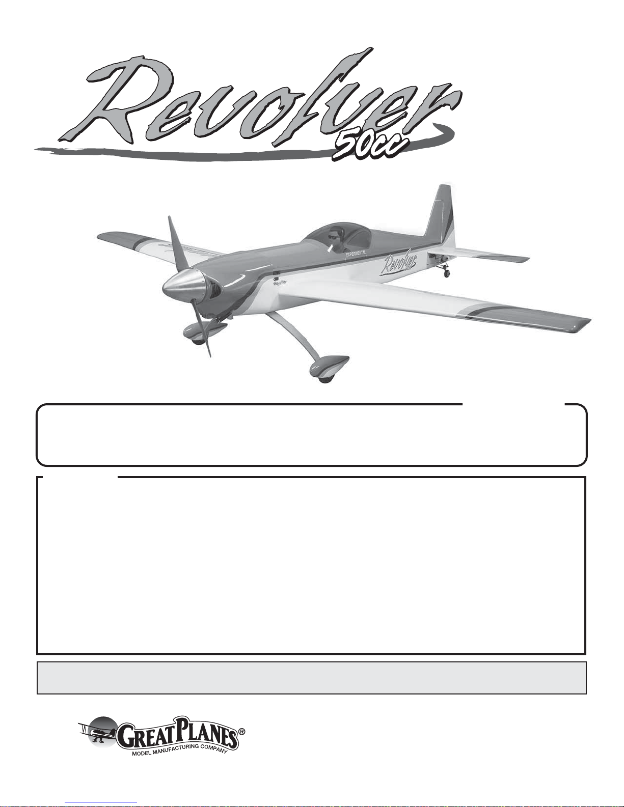
INSTRUCTION MANUAL
Wingspan: 90 in [2285 mm]
2
Wing Area: 1303 in
Wing Loading: 34−36 oz/ft
[84 dm2]
2
[104−110 g/dm2]
WARRANTY
Great Planes® Model Manufacturing Co. guarantees this kit to
be free from defects in both material and workmanship at the
date of purchase. This warranty does not cover any component
parts damaged by use or modification. In no case shall Great
Planes’ liability exceed the original cost of the purchased kit.
Further, Great Planes reserves the right to change or modify this
warranty without notice.
In that Great Planes has no control over the final assembly or
material used for final assembly, no liability shall be assumed nor
accepted for any damage resulting from the use by the user of
the final user-assembled product. By the act of using the
user-assembled product, the user accepts all resulting liability.
If the buyer is not prepared to accept the liability associated
with the use of this product, the buyer is advised to return
Weight: 19.5 − 20.5 lb [8840 − 9300 g]
Length: 82.5 in [2095 mm]
Radio: 4 channel minimum
this kit immediately in new and unused condition to the
place of purchase.
To make a warranty claim send the defective part or item to
Hobby Services at the address below:
Include a letter stating your name, return shipping address, as
much contact information as possible (daytime telephone
number, fax number, e-mail address), a detailed description of
the problem and a photocopy of the purchase receipt. Upon
receipt of the package the problem will be evaluated as quickly
as possible.
SPECIFICATIONS
Engine: 50 cc two stroke
gasoline engine
Hobby Services
3002 N. Apollo Dr. Suite 1
Champaign IL 61822 USA
READ THROUGH THIS MANUAL BEFORE STARTING CONSTRUCTION. IT CONTAINS IMPORTANT
INSTRUCTIONS AND WARNINGS CONCERNING THE ASSEMBLY AND USE OF THIS MODEL.
Entire Contents © 2012 Hobbico,® Inc. All rights reserved.
Champaign, Illinois (217) 398-8970
email: airsupport@greatplanes.com
GPMA1425 Mnl

TABLE OF CONTENTS
INTRODUCTION . . . . . . . . . . . . . . . . . . . . . . . . . . . . . . . . 2
Academy of Model Aeronautics . . . . . . . . . . . . . . . . . . 2
SAFETY PRECAUTIONS . . . . . . . . . . . . . . . . . . . . . . . . . 2
DECISIONS YOU MUST MAKE. . . . . . . . . . . . . . . . . . . . . 3
Radio Equipment . . . . . . . . . . . . . . . . . . . . . . . . . . . . . 3
Engine . . . . . . . . . . . . . . . . . . . . . . . . . . . . . . . . . . . . . 3
ADDITIONAL ITEMS REQUIRED . . . . . . . . . . . . . . . . . . . 3
Required Hardware & Accessories . . . . . . . . . . . . . . . 3
Adhesives & Building Supplies. . . . . . . . . . . . . . . . . . . 3
Optional Supplies & Tools . . . . . . . . . . . . . . . . . . . . . . 3
IMPORTANT BUILDING NOTES. . . . . . . . . . . . . . . . . . . . 3
KIT INSPECTION. . . . . . . . . . . . . . . . . . . . . . . . . . . . . . . . 4
ORDERING REPLACEMENT PARTS . . . . . . . . . . . . . . . . 4
KIT CONTENTS. . . . . . . . . . . . . . . . . . . . . . . . . . . . . . . . . 5
PREPARATIONS . . . . . . . . . . . . . . . . . . . . . . . . . . . . . . . . 5
BUILD THE WING . . . . . . . . . . . . . . . . . . . . . . . . . . . . . . . 5
BUILD THE FUSELAGE . . . . . . . . . . . . . . . . . . . . . . . . . . 8
Assemble the Tail Section . . . . . . . . . . . . . . . . . . . . . .8
Install the Elevator Servos . . . . . . . . . . . . . . . . . . . . . . 9
Install the Rudder. . . . . . . . . . . . . . . . . . . . . . . . . . . . 10
Install the Landing Gear. . . . . . . . . . . . . . . . . . . . . . . 11
Install the Rudder Servo & Pull-Pull Wires. . . . . . . . . 13
Install the Engine, Fuel Tank & Remaining Servos . . 14
Install the Radio System . . . . . . . . . . . . . . . . . . . . . . 19
Complete the Engine Installation,
Mount the Cowl, Prop & Spinner . . . . . . . . . . . . . 20
Apply the Decals . . . . . . . . . . . . . . . . . . . . . . . . . . . . 24
GET THE MODEL READY TO FLY . . . . . . . . . . . . . . . . . 24
Check the Control Directions . . . . . . . . . . . . . . . . . . . 24
Set the Control Throws. . . . . . . . . . . . . . . . . . . . . . . . 25
Balance the Model (C.G.). . . . . . . . . . . . . . . . . . . . . . 26
Balance the Model Laterally. . . . . . . . . . . . . . . . . . . . 26
PREFLIGHT . . . . . . . . . . . . . . . . . . . . . . . . . . . . . . . . . . . 27
Identify Your Model. . . . . . . . . . . . . . . . . . . . . . . . . . . 27
Charge the Batteries . . . . . . . . . . . . . . . . . . . . . . . . . 27
Balance Propellers. . . . . . . . . . . . . . . . . . . . . . . . . . . 27
Ground Check & Range Check . . . . . . . . . . . . . . . . . 27
ENGINE SAFETY PRECAUTIONS . . . . . . . . . . . . . . . . .27
AMA SAFETY CODE. . . . . . . . . . . . . . . . . . . . . . . . . . . . 28
General . . . . . . . . . . . . . . . . . . . . . . . . . . . . . . . . . . . 28
Radio Control . . . . . . . . . . . . . . . . . . . . . . . . . . . . . . . 28
CHECK LIST . . . . . . . . . . . . . . . . . . . . . . . . . . . . . . . . . . 28
FLYING. . . . . . . . . . . . . . . . . . . . . . . . . . . . . . . . . . . . . . . 29
Fuel Mixture Adjustments . . . . . . . . . . . . . . . . . . . . . 29
Takeoff . . . . . . . . . . . . . . . . . . . . . . . . . . . . . . . . . . . . 29
Flight . . . . . . . . . . . . . . . . . . . . . . . . . . . . . . . . . . . . . 29
Landing . . . . . . . . . . . . . . . . . . . . . . . . . . . . . . . . . . . 29
DLE55 MOUNTING PATTERN . . . . . . . . . . . . . . . . . . . .31
INTRODUCTION
Following the success of the .40 and .60 size Revolver we
have responded to your request for an even larger version.
This 50cc Revolver is a great fl ying airplane in the tradition
of its smaller counterparts and is an easy to transport giant
scale model. For the latest technical updates or manual
corrections to the Revolver, visit the Great Planes web site at
www.greatplanes.com. Open the “Airplanes” link, then select
the Revolver 50cc ARF. If there is new technical information
or changes to this model a “tech notice” box will appear in the
upper left corner of the page.
Academy of Model Aeronautics
If you are not already a member of the AMA, please join! The
AMA is the governing body of model aviation and membership
provides liability insurance coverage, protects modelers’ rights
and interests and is required to fl y at most R/C sites.
Academy of Model Aeronautics
5151 East Memorial Drive
Muncie, IN 47302-9252
Tele. (800) 435-9262
Fax (765) 741-0057
Or via the Internet at: http://www.modelaircraft.org
IMPORTANT!!! Two of the most important things you can
do to preserve the radio controlled aircraft hobby are to avoid
fl ying near full-scale aircraft and avoid fl ying near or over
groups of people.
SAFETY PRECAUTIONS
PROTECT YOUR MODEL, YOURSELF & OTHERS...
FOLLOW THESE IMPORTANT SAFETY PRECAUTIONS
1. Your Revolver should not be considered a toy, but rather a
sophisticated, working model that functions very much like
a full-size airplane. Because of its performance capabilities,
the Revolver, if not assembled and operated correctly, could
possibly cause injury to yourself or spectators and damage
to property.
2. You must assemble the model according to the instructions.
Do not alter or modify the model, as doing so may result in an
unsafe or unfl yable model. In a few cases the instructions may
differ slightly from the photos. In those instances the written
instructions should be considered as correct.
3. You must take time to build straight, true and strong.
4. You must use an R/C radio system that is in good condition,
a correctly sized engine, and other components as specifi ed
in this instruction manual. All components must be correctly
installed so that the model operates correctly on the ground
and in the air. You must check the operation of the model and
all components before every fl ight.
5. If you are not an experienced pilot or have not fl own this type
of model before, we recommend that you get the assistance
of an experienced pilot in your R/C club for your fi rst fl ights.
If you’re not a member of a club, your local hobby shop has
information about clubs in your area whose membership
includes experienced pilots.
6. While this kit has been fl ight tested to exceed normal use,
if the plane will be used for extremely high stress fl ying, such
as racing, or if an engine larger than one in the recommended
2

range is used, the modeler is responsible for taking steps to
reinforce the high stress points and/or substituting hardware
more suitable for the increased stress.
7. WARNING: The cowl and wheel pants included in this kit
are made of fi berglass, the fi bers of which may cause eye,
skin and respiratory tract irritation. Never blow into a part
(wheel pant, cowl) to remove fi berglass dust, as the dust
will blow back into your eyes. Always wear safety goggles, a
particle mask and rubber gloves when grinding, drilling and
sanding fi berglass parts. Vacuum the parts and the work area
thoroughly after working with fi berglass parts.
We, as the kit manufacturer, provide you with a top quality,
thoroughly tested kit and instructions, but ultimately the
quality and fl yability of your fi nished model depends on how
you build it; therefore, we cannot in any way guarantee the
performance of your completed model, and no representations
are expressed or implied as to the performance or safety of
your completed model.
Remember: Take your time and follow the instructions
to end up with a well-built model that is straight and true.
DECISIONS YOU MUST MAKE
❍ 2- Heavy Duty Dual Servo Lead (FUTM4135 for Futaba).
If you choose to use a dual servo lead or “Y” harnesses to
mix multiple servos you will need one for the elevator and
the ailerons. If you are using a 6 channel (or more) radio
then you may wish to operate each servo independently
and mix them through the radio.
❍ 2 - Heavy Duty Switch Harnesses (FUTM4385)
Engine
For all of our testing we used the DLE 55 (DLEG0055). Another
good choice would be the O.S. GT55 (OSMG1555), though
with this engine you will need to cut a bit more of the cowl
away for clearance for the carburetor. The Revolver fl ies well
with any of the 50cc class gasoline engines available and
has been designed to work with engines with the carburetor
linkage on either the left or right side of the fuselage.
ADDITIONAL ITEMS REQUIRED
Required Hardware & Accessories
This is the list of hardware and accessories required to fi nish
the Revolver. Order numbers are provided in parentheses.
This is a partial list of items required to fi nish the Revolver
50cc that may require planning or decision making before
starting to build. Order numbers are provided in parentheses.
Radio Equipment
One of the great things about the Revolver 50cc is that it does
not require a sophisticated radio. This airplane can be fl own
with something as simple as a four channel radio. We think
you will be able to enjoy all of the capabilities of this model
with the Futaba 6 EX (FUTK6900), the 7C (FUTK7004), or
the 8 FG Super (FUTK8010). The airplane will also require:
❍ 1- six (or more) channel receiver
❍ 5 - 99 oz. servos. Futaba 3305 (FUTM0045) Two required
for the elevator, two for the ailerons and one for the rudder.
❍ 2 - 50 oz. servos. Futaba 9001 (FUTM0075) One required
for the throttle. One is an optional servo that can be used
on the choke.
❍ 2 - 36" [914mm] Pro Series Heavy Duty Servo Extensions
(HCAM2726 for Futaba) for the elevator servos. One is
required if you use a dual servo extension to connect the
servos. Two if you use a separate lead to two separate
ports in the receiver.
❍ 3 - 12" [305mm] Pro Series Heavy Duty Servo Extensions
(HCAM2711 for Futaba). Two for the aileron servos and
one for the throttle.
❍ 2- 12" [305mm] Pro Series Heavy Duty Servo Extensions
(HCAM2711 for Futaba). These would be required if you do
not use “Y” connectors from your receiver to the ailerons.
❍ 1 - 6" Pro Series Heavy Duty Servo Extensions (HCAM2711
for Futaba) for the choke.
Adhesives & Building Supplies
This is the list of Adhesives and Building Supplies that are
required to fi nish the Revolver.
❍ 1/2 oz. [15g] Thin Pro CA (GPMR6001)
❍ 1 oz. [30g] Medium Pro CA+ (GPMR6008)
❍ Pro 6-minute epoxy (GPMR6045)
❍ Drill bits: 1/16" [1.6mm], 3/32" [2.4mm], 3/16" [4.8mm],
13/64" [5.2mm], 1/4" [6.4mm].
❍ Stick-on segmented lead weights (GPMQ4485)
❍ Silver solder w/fl ux (STAR2000)
❍ #1 Hobby knife (HCAR0105)
❍ #11 blades (5-pack, HCAR0211)
❍ 2 - 3' lengths of Tygon Fuel Tube (DUBQ0486)
Optional Supplies & Tools
Here is a list of optional tools mentioned in the manual that
will help you build the Revolver.
❍ Top Flite MonoKote sealing iron (TOPR2100)
❍ Top Flite Hot Sock iron cover (TOPR2175)
❍ 4 oz. [113g] aerosol CA activator (GPMR634)
❍ Mixing sticks (50, GPMR8055)
❍ Mixing cups (GPMR8056)
IMPORTANT BUILDING NOTES
● There are three types of screws used in this kit:
Sheet Metal Screws are designated by a number and a
length. For example #6 3/4" [19mm].
This is a number six screw
that is 3/4" [19mm] long.
3
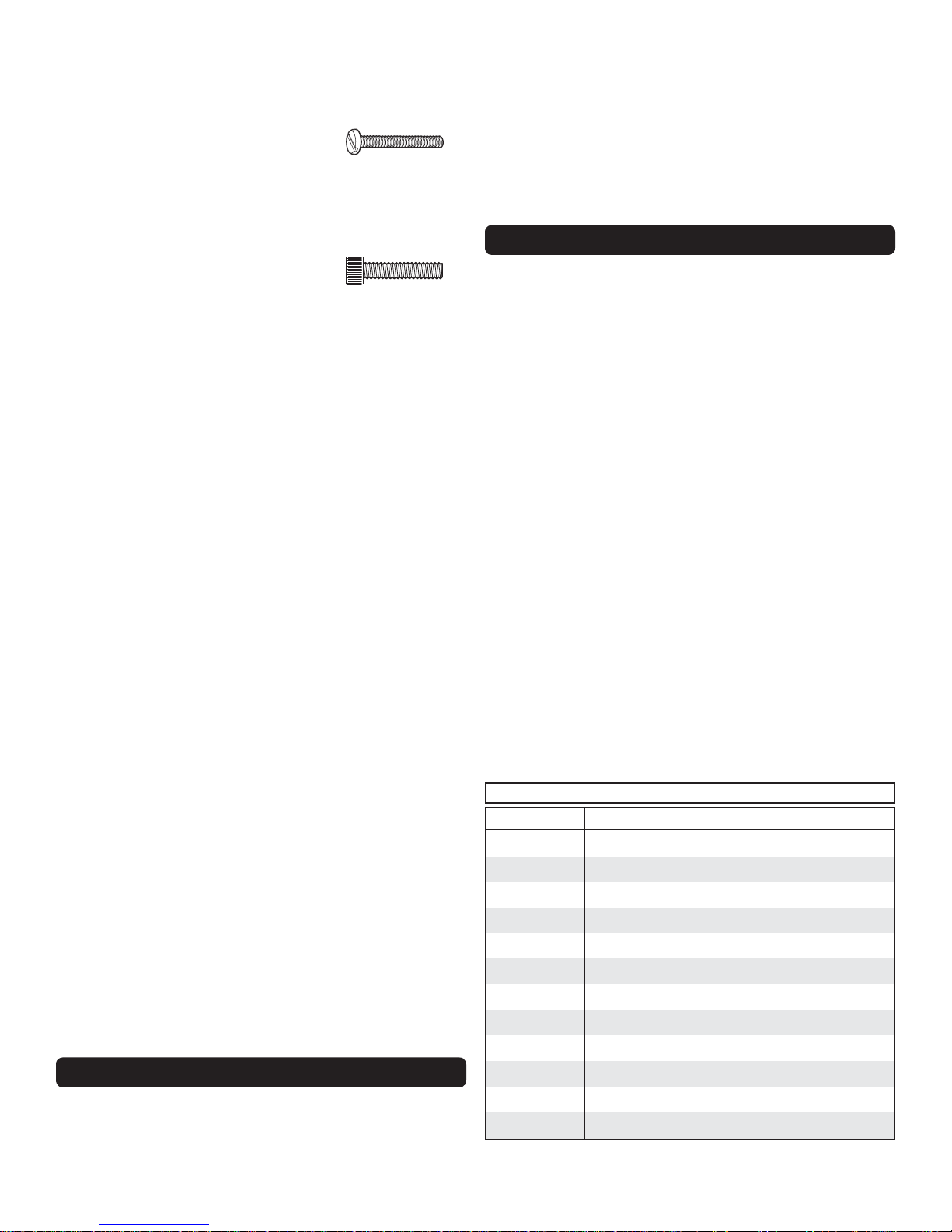
Machine Screws are designated by a number,
threads per inch, and a length. For example
4-40 3/4" [19mm].
This is a number four screw
that is 3/4" [19mm] long with
forty threads per inch.
Socket Head Cap Screws (SHCS) are designated by a
number, threads per inch, and a length. For example
4-40 3/4" [19mm].
This is a 4-40 SHCS that
is 3/4" [19mm] long with
forty threads per inch.
● When you see the term test fi t in the instructions, it means
that you should fi rst position the part on the assembly
without using any glue, then slightly modify or custom
fi t the part as necessary for the best fi t.
● Whenever the term glue is written you should rely upon
your experience to decide what type of glue to use. When
a specifi c type of adhesive works best for that step, the
instructions will make a recommendation.
● Whenever just epoxy is specifi ed you may use either
30-minute (or 45-minute) epoxy or 6-minute epoxy. When
30-minute epoxy is specifi ed it is highly recommended that
you use only 30-minute (or 45-minute) epoxy, because you
will need the working time and/or the additional strength.
● Photos and sketches are placed before the step they refer
to. Frequently you can study photos in following steps to
get another view of the same parts.
● The Revolver is factory-covered with Top Flite MonoKote fi lm.
Should repairs ever be required, MonoKote can be patched
with additional MonoKote purchased separately. MonoKote
is packaged in six-foot rolls, but some hobby shops also sell
it by the foot. If only a small piece of MonoKote is needed
for a minor patch, perhaps a fellow modeler would give you
some. MonoKote is applied with a model airplane covering
iron, but in an emergency a regular iron could be used. A
roll of MonoKote includes full instructions for application.
Following are the colors used on this model and order
numbers for six foot rolls.
❍ Missile Red ❍ Orange ❍ Sapphire Blue
(TOPQ0201) (TOPQ0202) (TOPQ0226)
● The stabilizer and wing incidences and engine thrust angles
have been factory-built into this model. However, some
technically-minded modelers may wish to check these
measurements anyway. To view this information visit the web
site at www.greatplanes.com and click on “Technical Data.”
Due to manufacturing tolerances which will have little or no
effect on the way your model will fl y, please expect slight
deviations between your model and the published values.
KIT INSPECTION
Before starting to build, take an inventory of this kit to make
sure it is complete, and inspect the parts to make sure they
are of acceptable quality. If any parts are missing or are not
of acceptable quality, or if you need assistance with assembly,
contact Product Support. When reporting defective or missing
parts, use the part names exactly as they are written in the
Kit Contents list.
Great Planes Product Support
3002 N Apollo Drive, Suite 1 Ph: (217) 398-8970, ext. 5
Champaign, IL 61822 Fax: (217) 398-7721
E-mail: airsupport@greatplanes.com
ORDERING REPLACEMENT PARTS
Replacement parts for the Great Planes Revolver ARF are
available using the order numbers in the Replacement Parts
List that follows. The fastest, most economical service can be
provided by your hobby dealer or mail-order company.
To locate a hobby dealer, visit the Great Planes web site at
www.greatplanes.com. Select “Where to Buy” in the menu
across the top of the page and follow the instructions provided
to locate a U.S., Canadian or International dealer.
Parts may also be ordered directly from Hobby Services by
calling (217) 398-0007, or via facsimile at (217) 398-7721, but
full retail prices and shipping and handling charges will apply.
Illinois and Nevada residents will also be charged sales tax. If
ordering via fax, include a Visa® or MasterCard® number and
expiration date for payment.
Mail parts orders Hobby Services
and payments by 3002 N Apollo Drive, Suite 1
personal check to: Champaign IL 61822
Be certain to specify the order number exactly as listed in the
Replacement Parts List. Payment by credit card or personal
check only; no C.O.D.
If additional assistance is required for any reason contact
Product Support by e-mail at productsupport@greatplanes.
com, or by telephone at (217) 398-8970.
REPLACEMENT PARTS LIST
Order No. Description
GPMA4520
GPMA4521
GPMA4522
GPMA4523
GPMA4524
GPMA4525
GPMA4527
GPMA4528
GPMA4529
GPMA4530
GPMA4531
TOPA1657
4
FUSELAGE
WING SET
HORIZONTAL STAB SET
RUDDER
COWL
CANOPY/HATCH
TAIL GEAR
WING JOINER TUBE
HORIZONTAL STAB TUBES
WHEELPANTS
DECALS
ALUMINUM SPINNER
KIT CONTENTS
4
Kit Contents
1. Right Wing w/ Aileron
2. Left Wing w/ Aileron
3. Wing Tube
4. Spinner
5. Wheels
6. Wheel Pants
16
8
7
6
5
7. Landing Gear
8. Fuel Tank
9. Right Stab & Elevator
10. Left Stab & Elevator
15
14
10
9
11
12
1
3
2
13
13. Rudder
14. Tail Wheel Assembly
15. Fuselage
16. Cowl
11. 19-3/4" [501mm] Stab Tube
12. 9-1/2" [241mm] Stab Tube
PREPARATIONS
1. If you have not done so already, remove the major parts
❏
of the kit from the box and inspect for damage. If any parts
are damaged or missing, contact Product Support at the
address or telephone number listed in the “Kit Inspection” on
the previous page.
2. Use a covering iron with a covering sock on high heat to
❏
tighten the covering if necessary. Apply pressure over sheeted
areas to thoroughly bond the covering to the wood.
BUILD THE WING
We recommend you begin with the right wing so that your
assembly matches the photos.
1. Use your servo as a guide for the servo placement.
❏ ❏
Place the servo so the servo arm is centered in the opening
in the cover. Use epoxy to glue the 11/16" x 11/16" x 5/16"
[20mm x 20mm x 8mm] hardwood servo mounting blocks to
the insides of the hatch covers. Allow the epoxy to cure.
5

2. Drill a 1/16" [1.6mm] hole in the hatch covers through
❏ ❏
the mounting blocks approximately 3/8" [9.5mm] deep. Thread
a #2 x 3/8" [9.5mm] fl at head wood screw into each hole
and back it out. Apply a drop of thin CA glue to each hole to
harden the wood. When the CA glue has dried, thread a #2
x 3/8" [9.5mm] fl at head screw into each of the four holes.
3. Cut three arms from a four-armed servo arm for each
❏ ❏
aileron servo. Enlarge the outer hole of each remaining arm
with a 5/64" [2mm] drill bit.
4. Attach a 12" [305mm] servo extension to the aileron
❏ ❏
servo and secure the connector using tape or heat shrink
tubing (not included). Center the servos with your radio system
and install the servo arms to the servos perpendicular to the
servo cases as shown. Be sure to reinstall the servo arm
screws into the servos.
6. Inside the servo bay a string is taped. Tie the string
❏ ❏
to the servo lead. Taped to the root rib you will fi nd the other
end of the string. Pull the string and the servo lead through
the wing.
7. Position the aileron servo hatch covers in place and
❏ ❏
drill a 1/16" [1.6mm] hole through the mounting holes and
into the hatch mounting blocks. Thread a #2 x 3/8" [9.5mm]
screw into each hole and back it out. Apply a drop of thin CA
to each hole to harden the wood. Install the hatch covers to the
wings using four #2 x 3/8" [9.5mm] and four #2 fl at washers.
5. Position the servos against the underside of the aileron
❏ ❏
servo hatch covers between the mounting blocks. Drill 1/16"
[1.6mm] holes through the mounting tabs on the servo cases
into the blocks. Thread a servo mounting screw (included with
the servo) into each hole and back it out. Apply a drop of thin
CA to each hole to harden the wood. When the CA has dried,
install the servos onto the hatch covers using the hardware
supplied with the servos.
6
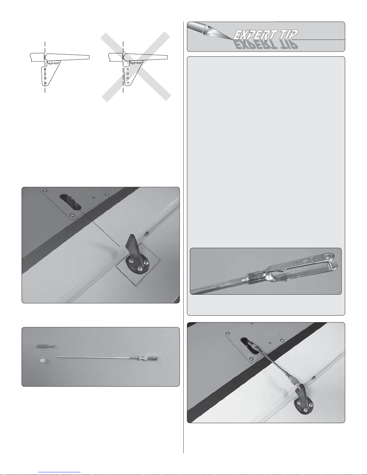
Hinge Line Hinge Line
CORRECT INCORRECT
8. The aileron has a plywood control horn mounting
❏ ❏
plate built into it. Place a control horn onto the plate in line
with the servo arm. Drill a 3/32" [2.4mm] hole through each
of the four mounting holes, into the plywood plate. DO NOT
DRILL THROUGH THE OPPOSITE SIDE OF THE AILERON!
9. Install and then remove a #4 x 5/8" sheet metal screw
❏ ❏
into the four holes you drilled. Apply a couple of drops of thin
CA glue into the holes to harden the threads. Allow the glue
to harden.
HOW TO SOLDER
1. Use denatured alcohol or other solvent to thoroughly
clean the pushrod. Roughen the end of the pushrod with
coarse sandpaper where it is to be soldered.
2. Apply a few drops of soldering fl ux to the end of the
pushrod, and then use a soldering iron or a torch to heat
it. “Tin” the heated area with silver solder by applying the
solder to the end. The heat of the pushrod should melt the
solder – not the fl ame of the torch or soldering iron – thus
allowing the solder to fl ow. The end of the wire should be
coated with solder all the way around.
3. Place the clevis on the end of the pushrod. Add another
drop of fl ux, then heat and add solder. The same as
before, the heat of the parts being soldered should melt
the solder, thus allowing it to fl ow. Allow the joint to cool
naturally without being disturbed. Avoid excess blobs, but
make certain the joint is thoroughly soldered. The solder
should be shiny, not rough. If necessary, reheat the joint
and allow to cool.
4. Immediately after the solder has solidifi ed, but while it
is still hot, use a cloth to quickly wipe off the fl ux before
it hardens. Important: After the joint cools, coat the joint
with oil to prevent rust. Note: Do not use the acid fl ux that
comes with silver solder for electrical soldering.
10. Secure the horn to the aileron with four #4 x 5/8"
❏ ❏
sheet metal screws.
11. Locate a 4-40 x 5-3/4" [146mm] threaded pushrod
❏ ❏
wire, 4-40 nut, 4-40 threaded clevis, 4-40 solder clevis and
two silicone clevis keepers. Assemble the pushrod as shown.
12. Install the pushrod assembly to the servo arm. Install
❏ ❏
the 4-40 solder clevis into the hole second from the end of the
control horn. Center the aileron and make a mark on the wire
where it will need to be cut. Remove the pushrod assembly
and the solder clevis. Cut the wire on the mark you made.
This is what a properly soldered clevis looks like –
shiny solder with good flow, no blobs and flux removed.
13. Using the instructions in the Expert Tip, “How To
❏ ❏
Solder”, install the 4-40 solder clevis onto the end of the
pushrod wire soldering the clevis to the wire. After the solder
7
has cooled slide the clevis retainer over the solder clevis.
Center you servo and then install the pushrod into the control
horn and the servo arm. Adjust the clevis as needed and then
tighten the 4-40 nut against the clevis. Be sure to apply a drop
of thread locker to the threaded wire and nut.
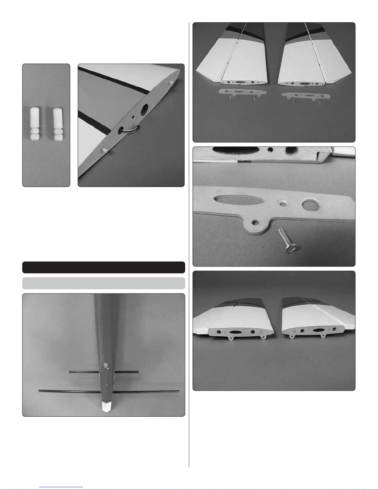
14. Locate two anti-rotation pins. Apply epoxy to the
❏ ❏
ribbed end of the pin and into the two holes at each end of
the root rib. Insert the pin into the hole leaving approximately
3/8" [9.5mm] of the pin extending from the root rib. Clean
any excess epoxy with denatured alcohol and a paper towel
before the glue hardens. Set the wing aside to allow the glue
to harden.
15. Repeat steps 1-14 for the left wing panel.
❏
BUILD THE FUSELAGE
Assemble the Tail Section
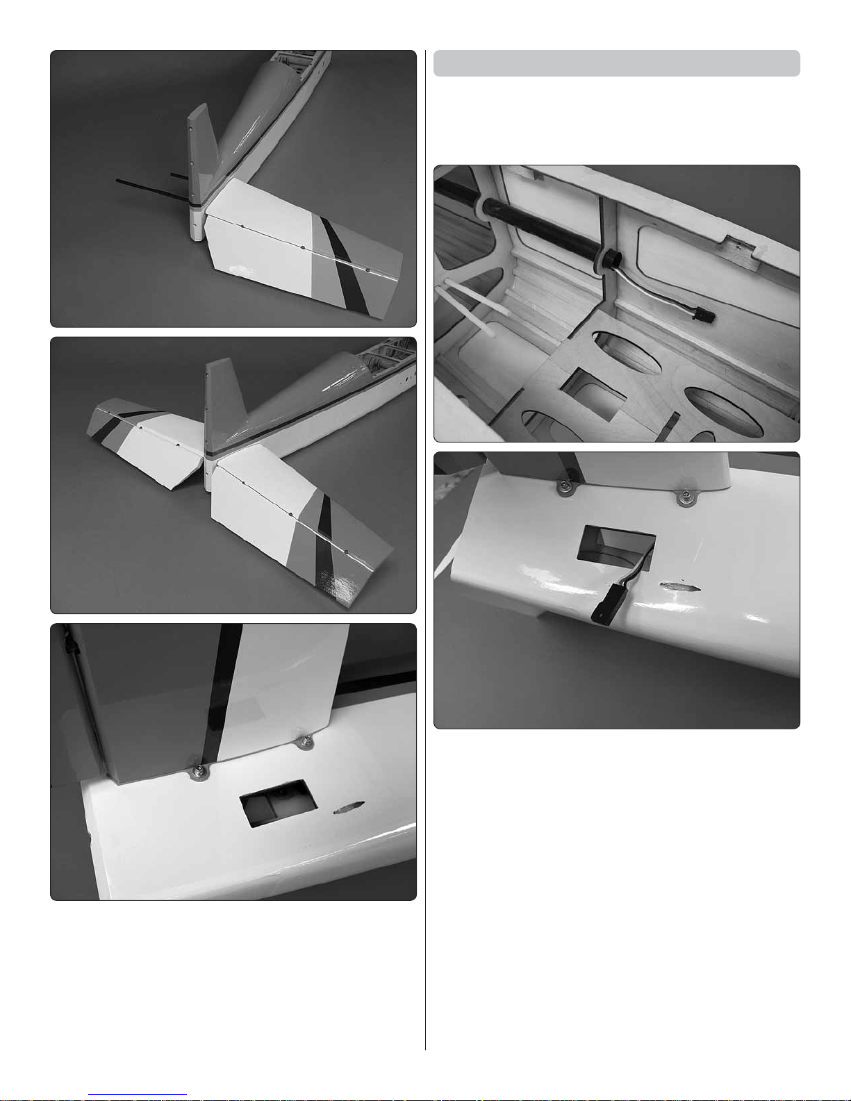
1. Locate the 9-1/2" [241mm] and 19-3/4" [501mm] carbon
❏
fi ber stab tubes. Insert them into the fuselage as shown.
2. Locate the left and right halves of the stab/elevator, two
❏
aluminum ribs and four 4-40 x1/2" [13mm] machine screws.
Install the aluminum ribs to each of the stabs with two 4-40
screws. Be sure that you use thread locker on each of the
screws. During the assembly be sure the side of the rib with
the counter sink faces the outside of the rib. This allows the
screw to be fl ush with the surface of the rib.
8
Install the Elevator Servos
Note: Steps 1 and 2 describe the installation of the servo
lead for the elevator servos. The installation described uses
one extension and a “Y” connector. Some might prefer a
separate line for each servo. Either method is acceptable.
3. Slide the stab assembly onto the carbon fi ber tubes, fl ush
❏
to the fuselage. Secure the stab to the fuselage with two 4-40
x1/2" [13mm] socket head cap screws, #4 lock washers and
#4 fl at washers. Be sure to use thread locker on each of the
bolts. Do this for both halves of the stab.
1. Install a 36" [914mm] servo extension into the tube, sliding
❏
the extension to the back of the fuselage. When it is through
the tube pull the extension outside one of the servo openings.
2. Install a “Y” connector onto the servo extension. Secure
❏
the connection with shrink tubing, tape or some other method
to secure the connection. Note: You may choose to use two
leads for the servos instead of the “Y” connector.
9
3. Using the hardware that came with your servo, set up
❏
two servos as shown and install them into the servo bays.
When installing the servos be sure that you secure the servo
connections with shrink tubing, tape or some other method
for securing the connections.
4. The elevator has a plywood control horn mounting plate
❏
built-in. Place a control horn onto the plate in line with the
servo arm. Drill a 3/32" [2.4mm] hole through each of the
four mounting holes, into the plywood plate. DO NOT DRILL
THROUGH THE OPPOSITE SIDE OF THE ELEVATOR!
7. Locate two 4-40 x 5-3/4" [146mm] threaded pushrod
❏
wires, 4-40 nuts, 4-40 threaded clevises, 4-40 solder clevises
and silicone clevis keepers. Use the same procedure used
for making the aileron pushrods and make two pushrod wires
for the elevators.
Install the Rudder
1. Locate four rudder
❏
hinges. Apply a drop of
oil to each of the hinge
points. This will prevent
glue from working into
the hinge.
5. Install and then remove a #4 x 5/8" sheet metal screw
❏
into the four holes you drilled. Apply a couple of drops of thin
CA glue into the holes to harden the threads. Allow the glue
to harden.
6. Secure the horn to the elevator with four #4 x 5/8" sheet
❏
metal screws.
2. Mix ¼ ounce [2 drams] of epoxy. Apply it to one half of
❏
the hinge and inside the hinge hole in the leading edge of
the rudder. Do this for each of the four hinges and then insert
each of the four hinges into the holes in the trailing edge of
the rudder. Clean any excess epoxy with a paper towel and
denatured alcohol. Set the rudder aside until the glue hardens.
3. Repeat step 2 for the opposite end of the hinge, gluing
❏
the rudder to the fuselage.
10
 Loading...