

Page 1
Maestro
MULTI-FORMAT MASTER CONTROL
Branding Engine Quick Start Guide
SOFTWARE VERSION 1.6.0
86225850
December 5, 2008
Page 2
Affiliate with the N.V. KEMA in The Netherlands
CERTIFICATE
Certificate Number: 510040.001
The Quality System of:
Grass Valley, Inc.
400 Providence Mine Road
Nevada City, CA 95945
United States
15655 SW Greystone Ct.
Beaverton, OR 97006
United States
10 Presidential Way
3
rd
Floor, Suite 300
Woburn, MA 01801
United States
Nederland B.V.
4800 RP BREDA
The Netherlands
Weiterstadt, Germany
Brunnenweg 9
D-64331 Weiterstadt
Germany
Rennes, France
Rue du Clos Courtel
Cesson-Sevigne, Cedex
France
Technopole Brest Iroise
CS 73808
29238 Brest Cedex 3
France
17 rue du Petit Albi-BP 8244
95801 Cergy Pontoise
Cergy, France
2300 South Decker Lake Blvd.
Salt Lake City, UT 84119
United States
7140 Baymeadows Way
Suite 101
Jacksonville, FL 32256
United States
Including its implementation, meets the requirements of the standard:
ISO 9001:2000
Scope:
The design, manufacture and support of video hardware and software products and
related systems.
This Certificate is valid until: June 14, 2009
This Certificate is valid as of: August 30, 2006
Certified for the first time: June 14, 2000
H. Pierre Sallé
President
KEMA-Registered Quality
The method of operation for quality certification is defined in the KEMA General Terms
And Conditions For Quality And Environmental Management Systems Certifications.
Integral publication of this certificate is allowed.
KEMA-Registered Quality, Inc.
4377 County Line Road
Chalfont, PA 18914
Ph: (215)997-4519
Fax: (215)997-3809
CRT 001 073004
ccredited By:
ANAB
A
Page 3
Maestro
MULTI-FORMAT MASTER CONTROL
Branding Engine Quick Start Guide
SOFTWARE VERSION 1.6.0
86225850
December 5, 2008
Page 4

—
4 Maestro — Branding Engine Quick Start Guide
Page 5
Contacting Grass Valley
International
Support Centers
Local Support
Centers
(available
during normal
business hours)
France
24 x 7
Australia and New Zealand: +61 1300 721 495 Central/South America: +55 11 5509 3443
Middle East: +971 4 299 64 40 Near East and Africa: +800 8080 2020 or +33 1 48 25 20 20
Europe
+800 8080 2020 or +33 1 48 25 20 20
+800 8080 2020 or +33 1 48 25 20 20
Hong Kong, Taiwan, Korea, Macau: +852 2531 3058 Indian Subcontinent: +91 22 24933476
Asia
Southeast Asia/Malaysia: +603 7805 3884 Southeast Asia/Singapore: +65 6379 1313
China: +861 0660 159 450 Japan: +81 3 5484 6868
Belarus, Russia, Tadzikistan, Ukraine, Uzbekistan: +7 095 2580924 225 Switzerland: +41 1 487 80 02
S. Europe/Italy-Roma: +39 06 87 20 35 28 -Milan: +39 02 48 41 46 58 S. Europe/Spain: +34 91 512 03 50
Benelux/Belgium: +32 (0) 2 334 90 30 Benelux/Netherlands: +31 (0) 35 62 38 42 1 N. Europe: +45 45 96 88 70
Germany, Austria, Eastern Europe: +49 6150 104 444 UK, Ireland, Israel: +44 118 923 0499
Copyright © Thomson. All rights reserved.
This product may be covered by one or more U.S. and foreign patents.
United States/Canada
24 x 7
+1 800 547 8949 or +1 530 478 4148
Grass Valley Web Site
The www.thomsongrassvalley.com web site offers the following:
Online User Documentation — Current versions of product catalogs, brochures,
data sheets, ordering guides, planning guides, manuals, and release notes
in .pdf format can be downloaded.
FAQ Database — Solutions to problems and troubleshooting efforts can be
found by searching our Frequently Asked Questions (FAQ) database.
Software Downloads — Download software updates, drivers, and patches.
5 Maestro — Branding Engine Quick Start Guide
Page 6

—
6 Maestro — Branding Engine Quick Start Guide
Page 7

Contents
About This Manual . . . . . . . . . . . . . . . . . . . . . . . . . . . . . . . . . . . . . . . . . . . . . . . . . . . . . 9
Safety Terms and Symbols. . . . . . . . . . . . . . . . . . . . . . . . . . . . . . . . . . . . . . . . . . . . . . 11
Terms in This Manual . . . . . . . . . . . . . . . . . . . . . . . . . . . . . . . . . . . . . . . . . . . . . . . . 11
Terms on the Product . . . . . . . . . . . . . . . . . . . . . . . . . . . . . . . . . . . . . . . . . . . . . . . . 11
Symbols on the Product . . . . . . . . . . . . . . . . . . . . . . . . . . . . . . . . . . . . . . . . . . . . . . 12
Warnings . . . . . . . . . . . . . . . . . . . . . . . . . . . . . . . . . . . . . . . . . . . . . . . . . . . . . . . . . . . . 12
Cautions . . . . . . . . . . . . . . . . . . . . . . . . . . . . . . . . . . . . . . . . . . . . . . . . . . . . . . . . . . . . . 13
Certifications and Compliances . . . . . . . . . . . . . . . . . . . . . . . . . . . . . . . . . . . . . . . . . 15
FCC Emission Control . . . . . . . . . . . . . . . . . . . . . . . . . . . . . . . . . . . . . . . . . . . . . . . 15
Canadian EMC Notice of Compliance . . . . . . . . . . . . . . . . . . . . . . . . . . . . . . . . . . 15
EN55022 Class A Warning . . . . . . . . . . . . . . . . . . . . . . . . . . . . . . . . . . . . . . . . . . . . 15
Canadian Certified Power Cords . . . . . . . . . . . . . . . . . . . . . . . . . . . . . . . . . . . . . . 16
Canadian Certified AC Adapter . . . . . . . . . . . . . . . . . . . . . . . . . . . . . . . . . . . . . . . 16
Laser Compliance . . . . . . . . . . . . . . . . . . . . . . . . . . . . . . . . . . . . . . . . . . . . . . . . . . . 16
Laser Safety Requirements . . . . . . . . . . . . . . . . . . . . . . . . . . . . . . . . . . . . . . . . . . 16
Laser Safety. . . . . . . . . . . . . . . . . . . . . . . . . . . . . . . . . . . . . . . . . . . . . . . . . . . . . . . 16
FCC Emission Limits . . . . . . . . . . . . . . . . . . . . . . . . . . . . . . . . . . . . . . . . . . . . . . . 17
Certifications: . . . . . . . . . . . . . . . . . . . . . . . . . . . . . . . . . . . . . . . . . . . . . . . . . . . . . . . 17
Section 1 — Software Installation. . . . . . . . . . . . . . . . . . . . . . . . . . . . . . . . . . . . . . 19
Software Upgrade Procedure . . . . . . . . . . . . . . . . . . . . . . . . . . . . . . . . . . . . . . . . . . . 19
Maestro Deployment PC . . . . . . . . . . . . . . . . . . . . . . . . . . . . . . . . . . . . . . . . . . . . . 19
Requirements . . . . . . . . . . . . . . . . . . . . . . . . . . . . . . . . . . . . . . . . . . . . . . . . . . . . . . . 19
Checking the Boot ROM Versions. . . . . . . . . . . . . . . . . . . . . . . . . . . . . . . . . . . . 20
Installing the Maestro Software Package . . . . . . . . . . . . . . . . . . . . . . . . . . . . . . 23
Manually Removing the Maestro Jupiter Router Service Software . . . . . . . . 27
Re-compiling the Configuration File. . . . . . . . . . . . . . . . . . . . . . . . . . . . . . . . . . 28
Updating the System Configuration and Software. . . . . . . . . . . . . . . . . . . . . . 29
Checking the GUI Control Panel for Proper LAN Settings. . . . . . . . . . . . . . . . . 33
Updating FPGAs/CPLDs. . . . . . . . . . . . . . . . . . . . . . . . . . . . . . . . . . . . . . . . . . . . . 34
Section 2 — Hardware Installation. . . . . . . . . . . . . . . . . . . . . . . . . . . . . . . . . . . . . 39
Branding Engine Board Installation. . . . . . . . . . . . . . . . . . . . . . . . . . . . . . . . . . . . . . 39
Branding Engine Hard Drive(s) Installation. . . . . . . . . . . . . . . . . . . . . . . . . . . . . . . 45
Mounting and Formatting Drives. . . . . . . . . . . . . . . . . . . . . . . . . . . . . . . . . . . . . . . . 50
Mounting a Drive . . . . . . . . . . . . . . . . . . . . . . . . . . . . . . . . . . . . . . . . . . . . . . . . . . . 50
Partitioning and Formatting a Drive . . . . . . . . . . . . . . . . . . . . . . . . . . . . . . . . . . . 51
Installing the Content Gateway . . . . . . . . . . . . . . . . . . . . . . . . . . . . . . . . . . . . . . . . . 54
Section 3 — Content Configuration. . . . . . . . . . . . . . . . . . . . . . . . . . . . . . . . . . . . . 61
Content Definition Table . . . . . . . . . . . . . . . . . . . . . . . . . . . . . . . . . . . . . . . . . . . . . . . 61
Content Input Table . . . . . . . . . . . . . . . . . . . . . . . . . . . . . . . . . . . . . . . . . . . . . . . . . . . 65
Input Table . . . . . . . . . . . . . . . . . . . . . . . . . . . . . . . . . . . . . . . . . . . . . . . . . . . . . . . . . . . 66
Maestro — Branding Engine Quick Start Guide 7
Page 8

Contents
Section 4 — Deploy and Verify Content . . . . . . . . . . . . . . . . . . . . . . . . . . . . . . . 71
Branding Element Deployment . . . . . . . . . . . . . . . . . . . . . . . . . . . . . . . . . . . . . . . . . 71
Verify Branding Element Deployment . . . . . . . . . . . . . . . . . . . . . . . . . . . . . . . . . . . 73
Verify Branding Element Assignment . . . . . . . . . . . . . . . . . . . . . . . . . . . . . . . . . . . 75
8 Maestro — Branding Engine Quick Start Guide
Page 9

Preface
About This Manual
This Quick Start Guide covers the installation, configuration, deployment,
and verification of all hardware and software associated with the Maestro
Branding Engine.
The 1.6.0 release of Maestro is the first version to support the Branding
Engine features. This manual focuses on the Branding Engine only and
does not address any other Maestro features included in the 1.6.0 release.
For more information on additional features supported in version 1.6.0, see
the version 1.6.0 Release Notes.
The Branding Engine is an optional feature that requires the purchase of
one or more Branding Engine mezzanine boards and disk drives. The 1.6.0
software release enables the Branding Engine features only if the appropriate hardware is installed.
Branding Engine hardware supports only the Maestro channel processor
on which it is installed. Each Maestro channel on which Branding Engine
features are desired must have at least one Branding Engine mezzanine
board and one hard disk drive installed. The contents of a Branding Engine
disk drive are not shared on multiple Maestro channel processors.
Maestro — Branding Engine Quick Start Guide 9
Page 10

Preface
10 Maestro — Branding Engine Quick Start Guide
Page 11

Safety Summary
Read and follow the important safety information below, noting especially
those instructions related to risk of fire, electric shock or injury to persons.
Additional specific warnings not listed here may be found throughout the
manual.
WARNING Any instructions in this manual that require opening the equipment cover
or enclosure are for use by qualified service personnel only. To reduce the
risk of electric shock, do not perform any servicing other than that contained in the operating instructions unless you are qualified to do so.
Safety Terms and Symbols
Terms in This Manual
Safety-related statements may appear in this manual in the following form:
WARNING Warning statements identify conditions or practices that may result in per-
sonal injury or loss of life.
CAUTION Caution statements identify conditions or practices that may result in damage
to equipment or other property, or which may cause equipment crucial to
your business environment to become temporarily non-operational.
Terms on the Product
The following terms may appear on the product:
DANGER — A personal injury hazard is immediately accessible as you read
the marking.
WARNING — A personal injury hazard exists but is not immediately acces-
sible as you read the marking.
CAUTION — A hazard to property, product, and other equipment is present.
Maestro — Branding Engine Quick Start Guide 11
Page 12
Safety Summary
Symbols on the Product
The following symbols may appear on the product:
Indicates that dangerous high voltage is present within the
equipment enclosure that may be of sufficient magnitude to
constitute a risk of electric shock.
Indicates that user, operator or service technician should refer
to product manual(s) for important operating, maintenance,
or service instructions.
This is a prompt to note fuse rating when replacing fuse(s).
The fuse referenced in the text must be replaced with one
having the ratings indicated.
Identifies a protective grounding terminal which must be connected to earth ground prior to making any other equipment
connections.
Warnings
Identifies an external protective grounding terminal which
may be connected to earth ground as a supplement to an
internal grounding terminal.
Indicates that static sensitive components are present which
may be damaged by electrostatic discharge. Use anti-static
procedures, equipment and surfaces during servicing.
The following warning statements identify conditions or practices that can
result in personal injury or loss of life.
Dangerous voltage or current may be present — Disconnect power and remove
battery (if applicable) before removing protective panels, soldering, or
replacing components.
Do not service alone — Do not internally service this product unless another
person capable of rendering first aid and resuscitation is present.
Remove jewelry — Prior to servicing, remove jewelry such as rings, watches,
and other metallic objects.
Avoid exposed circuitry — Do not touch exposed connections, components or
circuitry when power is present.
12 Maestro — Branding Engine Quick Start Guide
Page 13

Cautions
Use proper power cord — Use only the power cord supplied or specified for
this product.
Ground product — Connect the grounding conductor of the power cord to
earth ground.
Operate only with covers and enclosure panels in place — Do not operate this
product when covers or enclosure panels are removed.
Use correct fuse — Use only the fuse type and rating specified for this
product.
Use only in dry environment — Do not operate in wet or damp conditions.
Use only in non-explosive environment — Do not operate this product in an
explosive atmosphere.
High leakage current may be present — Earth connection of product is essential
before connecting power.
Dual power supplies may be present — Be certain to plug each power supply
cord into a separate branch circuit employing a separate service ground.
Disconnect both power supply cords prior to servicing.
Cautions
Double pole neutral fusing — Disconnect mains power prior to servicing.
Use proper lift points — Do not use door latches to lift or move equipment.
Avoid mechanical hazards — Allow all rotating devices to come to a stop before
servicing.
The following caution statements identify conditions or practices that can
result in damage to equipment or other property
Use correct power source — Do not operate this product from a power source
that applies more than the voltage specified for the product.
Use correct voltage setting — If this product lacks auto-ranging power sup-
plies, before applying power ensure that the each power supply is set to
match the power source.
Provide proper ventilation — To prevent product overheating, provide equip-
ment ventilation in accordance with installation instructions.
Use anti-static procedures — Static sensitive components are present which
may be damaged by electrostatic discharge. Use anti-static procedures,
equipment and surfaces during servicing.
Maestro — Branding Engine Quick Start Guide 13
Page 14

Safety Summary
Do not operate with suspected equipment failure — If you suspect product damage
or equipment failure, have the equipment inspected by qualified service
personnel.
Ensure mains disconnect — If mains switch is not provided, the power cord(s)
of this equipment provide the means of disconnection. The socket outlet
must be installed near the equipment and must be easily accessible. Verify
that all mains power is disconnected before installing or removing power
supplies and/or options.
Route cable properly — Route power cords and other cables so that they ar not
likely to be damaged. Properly support heavy cable bundles to avoid con-
nector damage.
Use correct power supply cords — Power cords for this equipment, if provided,
meet all North American electrical codes. Operation of this equipment at
voltages exceeding 130 VAC requires power supply cords which comply
with NEMA configurations. International power cords, if provided, have
the approval of the country of use.
Use correct replacement battery — This product may contain batteries. To
reduce the risk of explosion, check polarity and replace only with the same
or equivalent type recommended by manufacturer. Dispose of used bat-
teries according to the manufacturer’s instructions.
Troubleshoot only to board level — Circuit boards in this product are densely
populated with surface mount technology (SMT) components and applica-
tion specific integrated circuits (ASICS). As a result, circuit board repair at
the component level is very difficult in the field, if not impossible. For war-
ranty compliance, do not troubleshoot systems beyond the board level.
14 Maestro — Branding Engine Quick Start Guide
Page 15

Regulatory Notices
Certifications and Compliances
FCC Emission Control
This equipment has been tested and found to comply with the limits for a
Class A digital device, pursuant to Part 15 of the FCC Rules. These limits
are designed to provide reasonable protection against harmful interference
when the equipment is operated in a commercial environment. This equip
ment generates, uses, and can radiate radio frequency energy and, if not
installed and used in accordance with the instruction manual, may cause
harmful interference to radio communications. Operation of this equip
ment in a residential area is likely to cause harmful interference in which
case the user will be required to correct the interference at his own expense.
Changes or modifications not expressly approved by Grass Valley Group
can affect emission compliance and could void the user’s authority to
operate this equipment.
-
-
Canadian EMC Notice of Compliance
This digital apparatus does not exceed the Class A limits for radio noise
emissions from digital apparatus set out in the Radio Interference Regula
tions of the Canadian Department of Communications.
Le présent appareil numérique n’emet pas de bruits radioélectriques
dépassant les limites applicables aux appareils numeriques de la classe A
préscrites dans le Règlement sur le brouillage radioélectrique édicte par le
ministère des Communications du Canada.
EN55022 Class A Warning
In a domestic environment, products that comply with Class A may cause
radio interference in which case the user may be required to take adequate
measures.
-
Maestro — Branding Engine Quick Start Guide 15
Page 16

Regulatory Notices
Canadian Certified Power Cords
Canadian Certified AC Adapter
Laser Compliance
Laser Safety Requirements
Canadian approval includes the products and power cords appropriate for
use in the North America power network. All other power cords supplied
are approved for the country of use.
Canadian approval includes the AC adapters appropriate for use in the
North America power network. All other AC adapters supplied are
approved for the country of use.
The device used in this product is a Class 1 certified laser product. Oper-
ating this product outside specifications or altering from its original design
may result in hazardous radiation exposure, and may be considered an act
of modifying or new manufacturing of a laser product under U.S. regula
tions contained in 21CFR Chapter 1, subchapter J or CENELEC regulations
in HD 482 S1. People performing such an act are required by law to recertify
and reidentify this product in accordance with provisions of 21CFR sub
chapter J for distribution within the U.S.A., and in accordance with
CENELEC HD 482 S1 for distribution within countries using the IEC 825
standard.
-
-
Laser Safety
Laser safety in the United States is regulated by the Center for Devices and
Radiological Health (CDRH). The laser safety regulations are published in
the “Laser Product Performance Standard,” Code of Federal Regulation
(CFR), Title 21, Subchapter J.
The International Electrotechnical Commission (IEC) Standard 825, “Radi-
ation of Laser Products, Equipment Classification, Requirements and
User’s Guide,” governs laser products outside the United States. Europe
and member nations of the European Free Trade Association fall under the
jurisdiction of the Comite European de Normalization Electrotechnique
(CENELEC).
For the CDRH: The radiant power is detected through a 7 mm aperture at
a distance of 200 mm from the source focused through a lens with a focal
length of 100 mm.
For IEC compliance: The radiant power is detected through a 7 mm aper-
ture at a distance of 100 mm from the source focused through a lens with a
focal length of 100 mm.
16 Maestro — Branding Engine Quick Start Guide
Page 17
FCC Emission Limits
Certifications:
Category Standard Designed/tested for compliance with:
ANSI / UL60950 “Standard for Safety of Information Technology Equipment - Safety - Part 1: General
IEC 60950 “Standard for Safety for Information Technology Equipment - Safety - Part 1: General
Safety
EMI
CAN/CSA C22.2, No. 60950 “Standard for Safety of Information Technology Equipment - Safety - Part 1: General
EN60950 Safety of Information Technology Equipment, including Electrical Business Equipment.
73/23/EEC Low Voltage Directive
EMC Directive 89/336/EEC via
EN 55103-1 and 2
EN 55103-1 standards Electromagnetic compatibility.
EN55103-2 standards Electromagnetic compatibility--Product family standard for audio, video, audio-visual
US FCC Class A
Canada FCC Industry Canada
Australia & New Zealand: AS/NZS 3548
Certifications and Compliances
This device complies with Part 15 of the FCC Rules. Operation is subject to
the following two conditions: (1) This device may not cause harmful inter
ference, and (2) this device must accept any interference received,
including interference that may cause undesirable operation. This device
has been tested and found to comply with FCC Part 15 Class B limits for a
digital device when tested with a representative laser-based fiber optical
system that complies with ANSI X3T11 Fiber Channel Standard.
Requirements”, (ANSI/UL 60950-1, First Edition, Dated April 1, 2003, with revision
through and including November 26, 2003.)
Requirements”, (IEC 60950-1, First Edition, 2001, Corrigendum 1:10-2002)
Requirements”, (CAN/CSA-C22.2 No. 60950-1-03. First Edition Dated April 1, 2003,
with revisions through and including November 26, 2003)
Audio, Video and Entertainment Lighting Control for the European Community.
Product family standard for audio, video, audio-visual and entertainment lighting control
apparatus for professional use.
Part 1 Emissions, Environment E1/E2
EN 55022: Class A Radiated and Conducted Emissions
EN 61000-3-2: Power Line Harmonic Emissions, Radiated Magnetic Field Emissions,
Peak Inrush Current
and entertainment lighting control apparatus for professional use.
Part 2 Immunity, Environment E1/E2
EN 50082-1: Immunity
EN 61000-4-2:
Electrostatic Discharge “ESD” Immunity
EN 61000-4-3:
Radiated RF Electromagnetic Field Immunity
EN 61000-4-4:
Electrical Fast Transient/Burst “EFT” Immunity
EN 61000-4-5: Surge Immunity
EN 61000-4-6: Conducted RF Immunity
EN 61000-4-11: Voltage Dips, Short Interruptions and Voltage Variations
Annex A - Radiated Magnetic Field Immunity
Note: This only applies to assemblies sensitive to magnetic fields
CISPR Pub. 22 (1985)
-
IMPORTANT NOTE TO WRITERS - SEE THE FOLLOWING PARAGRAPHS AND DELETE THIS
TEXT BEFORE PUBLICATION.
Maestro — Branding Engine Quick Start Guide 17
Page 18
Regulatory Notices
THE INFORMATION IN THE CERTIFICATION TABLES ABOVE MUST BE REVIEWED TO CONFIRM THE PROPER COMPLIANCE NOTICES ARE INCLUDED. STANDARDS MAY HAVE
CHANGED SINCE THIS BOILERPLATE INFORMATION WAS DRAFTED. REGULATORY COMPLIANCE IS ESTABLISHED WHEN THE PRODUCT IS RELEASED THE FIRST TIME. THAT COMPLIANCE LEVEL IS RETAINED UNLESS THE PRODUCT OR MARKET CHANGES IN SOME WAY
THAT REQUIRES NEW COMPLIANCE TESTING. DO NOT BLINDLY REPLACE INFORMATION
IN OLDER MANUALS WITH THIS BOILERPLATE INFORMATION. CHECK WITH THE PRODUCT MANAGER TO CONFIRM WHAT NOTICES ARE REQUIRED.
SOME OLDER PRODUCTS (KAYAK DD FOR EXAMPLE) MAY REQUIRE OLDER “UL1419” SAFETY INFORMATION. THE INFORMATION BELOW REPLACES THE “ANSI/UL60950” SAFETY INFORMATION LISTED AS THE FIRST ITEM IN THE TABLE ABOVE FOR THESE OLD PRODUCTS.
Category Standard Designed/tested for compliance with:
Safety UL1419 Professional Video and Audio Equipment
18 Maestro — Branding Engine Quick Start Guide
Page 19

Software Installation
This section describes the installation procedure for the Maestro Branding
Engine software. Particular attention must be given to the section
the Boot ROM Versions on page 20. The boot ROM must be current before
installing the Branding Engine hardware.
Software Upgrade Procedure
CAUTION Portions of this procedure will interrupt video and audio signals passing
through the system. Users of this equipment should consult with Grass
Valley Technical Support personnel before proceeding.
Section 1
Checking
Maestro Deployment PC
Note In some installations, the “Deployment PC” will be the same as the GUI PC.
Requirements
• A period of time where the Maestro system can be taken off-line (externally bypassed).
• Windows XP with Service Pack 2 or greater.
• In order to upgrade the Maestro software, the Maestro configuration
computer will need access to the installation CD or downloaded installation files.
• The configuration from the existing operational Maestro system will be
used to complete the Maestro upgrade.
Maestro — Branding Engine Quick Start Guide 19
Page 20

Section 1 — Software Installation
Checking the Boot ROM Versions
Before proceeding with the installation of the Maestro Branding Engine
hardware, you must verify the boot ROM version that is installed on the
Maestro processor board. The boot ROM must be updated to the current
version or the processor board will not boot properly with the Branding
Engine hardware installed. See Section 2-Hardware Installation for Branding
Engine hardware installation instructions.
Note Most Maestro processor boards will have the current boot ROM installed.
Maestro software version 1.4 and higher require the Processor and hardware control panel boot ROMs to be current. Older versions of the boot
ROMs will operate under v1.4 and higher but this would require the
deployment PC and system software to be active at all times.
Note The procedure documented in this section can only be done after upgrading
Only early board shipments will have the older boot ROM installed.
to v1.5 or higher of the Maestro Software Package and updating the software
application as described in Updating the System Configuration and Software
on page 29. Previous software versions do not support checking the Boot
ROM version in the manner described below. If you have not upgraded to the
v1.5 or higher software, you must use the Telnet procedure documented in
the v1.4 Release Notes.
1. In the Maestro Deployment Control Center window, select the
Processor for which you wish to check the Boot ROM version. The row
for the selected Processor will have a dark background.
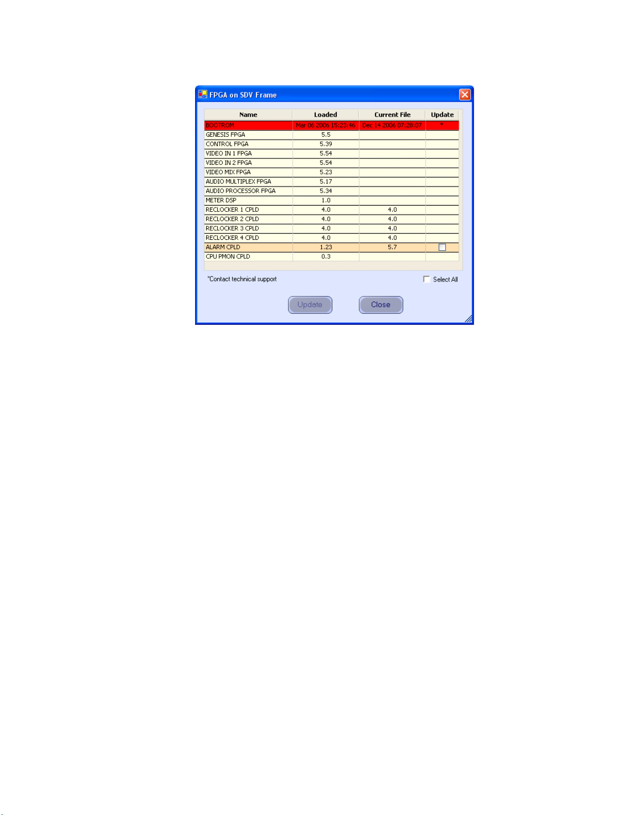
2. Right-click on the FPGA version number in the “Running>>” row of
the selected Processor. A window similar to the one seen in Figure 1
appears.
20 Maestro — Branding Engine Quick Start Guide
Page 21
Software Upgrade Procedure
Figure 1. Processor Board Boot ROM and FPGA/CPLD Update Window
3. Verify that the date that appears in the “Loaded” column for the
BOOTROM is Dec 14 2006.
• If, as in the example in Figure 1, you see an older date, or no date at
all, the Boot ROM should be updated.
Note Contact Grass Valley Technical Support if the Boot ROM is not current.
4. If there is another Processor (channel) in the system, repeat Step 1
above and following steps. If not, go to Step 5.
5. In the Maestro Deployment Control Center window, select the control
panel for which you wish to check the Boot ROM version.
For a hardware control panel, this will be a CP Panel Server board. For
a GUI control panel, this will be a PCI Panel Server board.
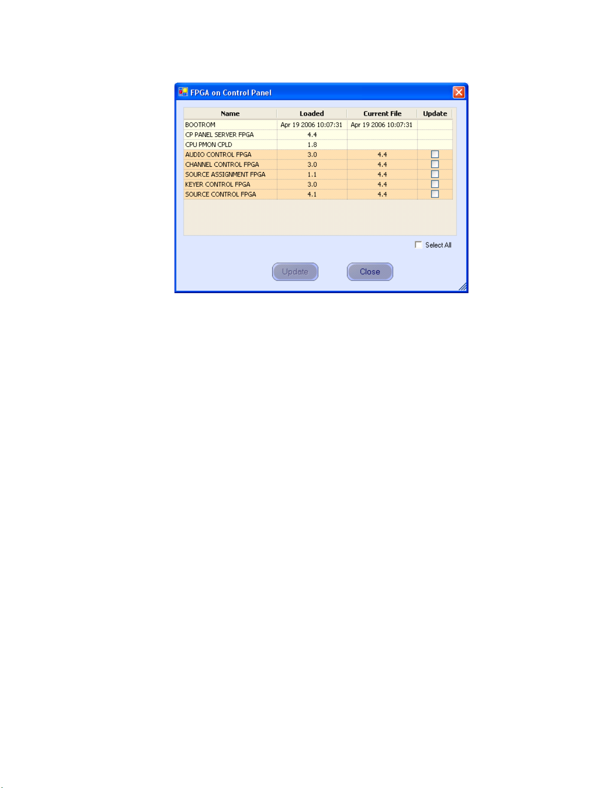
6. Right-click on the FPGA version number in the “Running>>” row of
the selected Control Panel. A window similar to the one seen in Figure 2
appears.
Maestro — Branding Engine Quick Start Guide 21
Page 22
Section 1 — Software Installation
Figure 2. Control Panel Boot ROM and FPGA/CPLD Update Window
7. Verify that the date that appears in the “Loaded” column for the
BOOTROM is Apr 19 2006.
• If you see an older date, or no date at all, the Boot ROM should be
updated. Contact Grass Valley Technical Support for update
instructions before proceeding.
• If the Boot ROM version is current, go to Step 8.
8. If there is another control panel in the system, repeat Step 5 above and
following steps. If all boot ROMs are current, proceed to Installing the
Maestro Software Package on page 23.
22 Maestro — Branding Engine Quick Start Guide
Page 23

Installing the Maestro Software Package
Note It is recommended that all default values be used during the installation.
1. Make a copy of the current configuration set:
a. Launch the Maestro Configuration Editor by going to “Start > All
Programs > Thomson > Maestro Configuration Editor.”
b. Use “File > Open” from the Menu bar to open the current
configuration set.
c. Use “File > Save As” to create a copy of the set.
As a suggestion, add “v151” to the name.
d. Use “File > Save As” again to create another copy of the set.
As a suggestion, add “v16” to the name.
e. Close all Maestro applications.
2. The previous version of Maestro software must be uninstalled before a
new version can be installed. The software can be manually removed
by following the steps below. It can also be automatically removed by
initiating the new software installation procedure in Step 3.
Software Upgrade Procedure
CAUTION If you are uninstalling v1.3, v1.4, v1.5, or v1.5.1 software, you must use the
Administrator account (login). If you are uninstalling v1.2 or prior software,
you must use the account (login) used when that software was installed.
a. Using the Windows Control Panel, select Add or Remove
Programs.
b. Remove the Maestro Software Package.
This will not remove user data.
c. Close the Windows Control Panel.
3. Insert the new Maestro software CD.
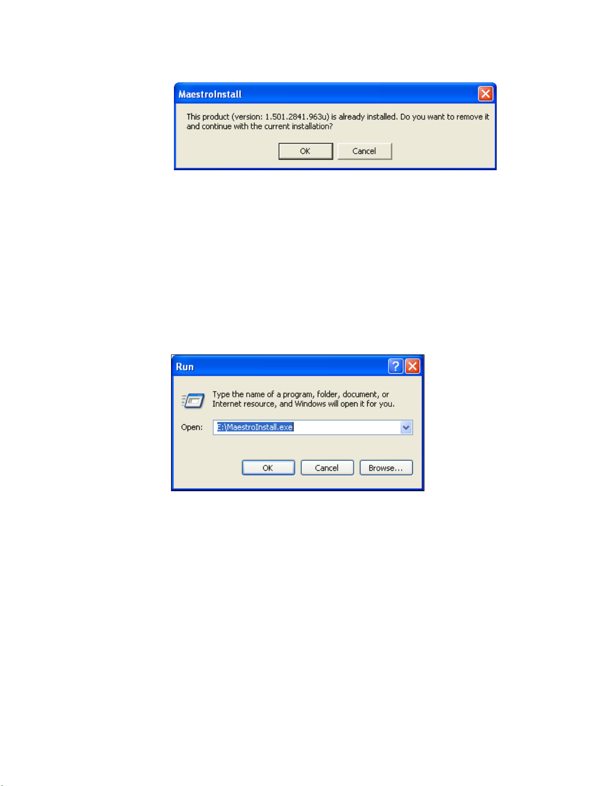
As shown in Figure 3, when the installation auto runs from the CD, or
is started manually by running “MaestroInstall.exe, previously
installed Maestro software is automatically detected. The operator is
prompted to confirm uninstallation of this software before proceeding
with the installation of the new software.
Maestro — Branding Engine Quick Start Guide 23
Page 24
Section 1 — Software Installation
Figure 3. Automatic Detection of Prior Software Version
A window similar to that shown in Figure 4 should appear.
a. Click the OK button to proceed with removal of the previous
software version.
A popup will then appear that asks if the install should continue. Click
Next button. Go to Step 4.
the
If the installation does not start automatically, the process will need to
be started manually:
b. Select Start > Run.
Figure 4. Run Dialog Box
c. Enter “E:\MaestroInstall.exe” where E: is the CD Drive.
d. Click the OK button.
Note If you enter “Setup.exe” in the Run dialog box instead of ‘MaestroInstall.exe,”
the window in Figure 5 appears and the prior Maestro software version must
be manually removed through Add/Remove Programs in the Windows
Control Panel. If this window appears, click the OK button and return to
Step 2 on page 23.
24 Maestro — Branding Engine Quick Start Guide
Page 25

Software Upgrade Procedure
Figure 5. Setup.exe Add/Remove Programs Prompt
A popup will then appear that asks if the install should continue; click
Next button. Go to Step 4.
the
4. A popup will indicate the default destination folder, click the Next
button.
5. For Setup Type, select Complete.
6. When the “Ready to Install” menu appears, click the Install button.
The window shown in Figure 6 will appear.
Figure 6. Installing Maestro Software Package
When the software installation is complete, the window shown in Figure 7
will appear.
Maestro — Branding Engine Quick Start Guide 25
Page 26

Section 1 — Software Installation
Figure 7. Maestro Software Package Installation Complete
7. Click the Finish button.
Installation of the Maestro Software Package on the PC is now complete.
Note If the installation fails to complete and you see the error message “Error 1001
-- the specified service already exists,” you may need to manually remove the
Maestro Jupiter Router Service software. Refer to Manually Removing the
Maestro Jupiter Router Service Software on page 27.
26 Maestro — Branding Engine Quick Start Guide
Page 27

Software Upgrade Procedure
Manually Removing the Maestro Jupiter Router Service Software
Perform this procedure only if you see the error message “Error 1001 -- the
specified service already exists” referred to in the Note on
1. Go to “Control Panel > Administrative Tools > Services.”
2. Right click on “MaestroJupiterRouterService” and select Stop.
3. Go to “Start > Run” and enter “regedit.”
4. Go to “HKEY_LOCAL_MACHINE > SYSTEM > CurrentControlSet >
Services.”
5. Highlight “MaestroJupiterRouterService.” Right click and delete this
item.
6. Close all windows and reboot. Repeat Step 1 above and confirm that
MaestroJupiterRouterService is not listed.
7. Proceed with re-installation of the new software, starting with Step 3 on
page 23.
page 26.
Maestro — Branding Engine Quick Start Guide 27
Page 28

Section 1 — Software Installation
Re-compiling the Configuration File
It is required that all configuration sets to be used with Maestro software
version 1.6.0 be recompiled with the 1.6.0 Configuration Editor. This will
add the following:
• The Content Definition table.
• The Content Input table.
• The VBI Passthrough table.
• The Clean Feed 1 and Clean Feed 2 configuration columns in the
• The Channel Delegation Subpanel Configuration Set column in the
Note The Channel Delegation Subpanel table has changed and may require recon-
Recompiling is also required if performing a software update when the
prior software was v1.3 or older. Changes have been made to the structure
of the Monitor Follow configuration table.
Channel Setup table.
Channel Server table.
figuration.
1. Launch the Maestro Configuration Editor by going to “Start > All
Programs > Thomson > Maestro Configuration Editor.”
2. Select the Maestro configuration set to be re-compiled by going to “File
> Open > Thomson” and selecting the set.
This should be the configuration set created for v1.6.0 use (Step d on
page 23).
3. If the system displays a Validation Report, you must check the
indicated table(s) and make corrections as indicated.
You can use the links in the Description column to display the table(s).
4. Save the configuration file.
5. Compile the file by going to “File > Compile Channel Data.”
6. Proceed to Updating the System Configuration and Software below.
28 Maestro — Branding Engine Quick Start Guide
Page 29

Updating the System Configuration and Software
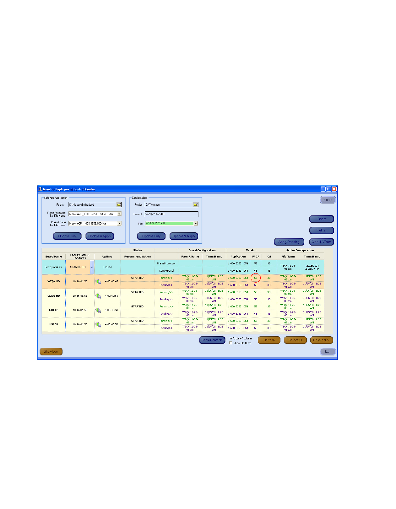
1. Launch the Maestro Deployment control center by selecting “Start > All
Programs > Thomson > Maestro Deployment Center.
A Maestro Deployment Control Center window similar to that shown
Figure 8 appears.
in
Figure 8. Maestro Deployment Control Center (Example)
Software Upgrade Procedure
2. (Optional) Select Show Log to provide detailed monitoring of the update
process.
3. In the Configuration box:
a. Verify that the Folder field has the correct path to the Maestro
configuration directory. (Default = C:\Thomson)
b. In the “File:” drop down field, select the Maestro configuration set
to be activated.
This should be the configuration set updated and compiled for v1.6.0
Step 5 on page 28).
use (
Maestro — Branding Engine Quick Start Guide 29
Page 30

Section 1 — Software Installation
The Configuration box contains two buttons: Update Only and Update and
Apply
4. Click the Update Only button.
Note When the Update Only button is clicked, the configuration file does not
.
Update Only - Downloads the selected configuration file to the
•
boards, but, does not apply it as the running configuration. The
selected configuration files appears in the “Pending>>” row.
The currently active configuration appears in the “Running>>”
rows.
Update & Apply - Downloads the selected configuration file to the
•
boards and applies it as the running configuration.
This action will update the contents of the “Pending>>” row in the
Board Configuration and Active Configuration columns. See
Figure 8.
become the active configuration until the Apply Pending button is clicked to
activate the “pending” configuration.
CAUTION The following step will interrupt the video and audio signals passing through
the system for about 1 minute.
5. In the Software Application box:
a. The “Folder” field should indicate “C:\MaestroEmbedded.”
b. In the Frame Processor Tar File Name field:
--For LTC systems (those using Linear Time Code) select
“MaestroMC_1.600.3353.1054.LTC.tar.” (When used, LTC is con
nected to pins 43 and 44 of the GPIO connector on the rear panel.)
--For VITC systems (those using Vertical Interval Time Code) select
“MaestroMC_1.600.3353.1054.VITC.tar.”
c. In the Control Panel Tar File Name, field, select
“MaestroCP_1.600.3353.1054.tar.”
6. Click the Select All button (lower right corner of menu).
Alternatively, each board can be updated independently by clicking on
the "Board Name" field or all at the same time by using the "Select All"
button.
-
30 Maestro — Branding Engine Quick Start Guide
Page 31

Software Upgrade Procedure
The Software Application box contains two buttons: Update Only and Update
and Apply
CAUTION The following step will interrupt the video and audio signals passing through
7. Click the Update & Apply button.
Note If the Update Only button is clicked, the software application file does not
.
Update Only - Downloads the selected configuration file to the
•
boards, but, does not apply it as the running configuration. The
selected configuration files appears in the “Pending>>” row.
The currently active configuration appears in the “Running>>”
rows.
Update & Apply - Downloads the selected configuration file to the
•
boards and applies it as the running configuration.
the system for about 1 minute.
This action will update the contents of the “Running>>” rows in the
Version columns and activate the application, FPGA and OS code.
become the active software application until the Apply Pending button is
clicked to activate the “pending” software application.
8. Click the Apply Pending button to activate the pending configuration and
make it the “Running” configuration.
9. Verify that the new Configuration and Application versions are
“Running” as seen in Figure 9.
10. Proceed to Checking the GUI Control Panel for Proper LAN Settings on
page 33.
Maestro — Branding Engine Quick Start Guide 31
Page 32

Section 1 — Software Installation
Figure 9. Maestro Deployment Control Center Software Version Status
32 Maestro — Branding Engine Quick Start Guide
Page 33

Software Upgrade Procedure
Checking the GUI Control Panel for Proper LAN Settings
Beginning with Maestro software version 1.4, the “Panel Server IP” address
and the "Local IP” address for the Maestro GUI must now use control LAN
addresses only. In releases prior to 1.4, the GUI application would connect
and run over the facility LAN; this is no longer possible with version 1.6.0.
The following steps should be taken to ensure that the GUI application is
set for the correct addresses:
1. With Maestro’s GUI up and running, click the Settings button. This will
open the Application Settings window.
2. Double-click (or select and click the Alter button) the Panel Server IP
setting.
3. Specify the control LAN address of the Panel Server card associated
with the GUI.
This will switch the view back to the first Application Settings window.
To look up the GUI control LAN address, go to “Maestro Configuration
Editor > Network Description Table.” Then check the Board Type
“GUI” row and the “Control LAN IP Address” column.
4. Double-click (or select and press Alter) the Local IP setting.
5. Select the control LAN address of the PC associated with the GUI.
This will switch the view back to the first Application Settings window.
To look up the PC control LAN address, go to “Start > Control Panel >
Network Connections.” Double-click on the card used for the control
LAN. Then go to Properties > Internet Protocol > Properties.
6. Close the Application Settings window. The GUI should then connect
and work properly.
Note If you have difficulty making this change or if the GUI is not functioning prop-
erly after this change, please contact Technical Support.
7. Proceed to Updating FPGAs/CPLDs on page 34.
Maestro — Branding Engine Quick Start Guide 33
Page 34
Section 1 — Software Installation
Updating FPGAs/CPLDs
1. Updating FPGAs/CPLDs on the Processor board(s):
Note Some of the FPGAs on the Processor are updated using the Software Version
Figure 10. “Running” FPGA Version
(FPGA = Field Programmable Gate Array. CPLD = Complex Programmable Logic Device.)
Update and Apply procedure described above. The remaining FPGAs on the
Processor are updated using the procedure below.
a. In the board Status section of the Maestro Deployment control
center, select the Processor to update.
b. Right-click on the “Running” FPGA field for this Processor. See
Figure 10.
This will display the FPGA/CPLD update menu. See Figure 11.
34 Maestro — Branding Engine Quick Start Guide
Page 35

Figure 11. Processor Board FPGA/CPLD Update Menu
Software Upgrade Procedure
This menu shows the names of all FPGAs/CPLDs on the Processor
and the version number of the gateware currently running
(“Loaded”) in each device. Certain of the FPGA-type components
and all of the CPLD-type components can be updated using this
menu, and if a newer (“current”) version of gateware is available for
those components the menu will indicate the new version number
and display a check box.
Note A Current version may have a smaller number than the corresponding Loaded
version. If FPGA/CPLD updates were performed with prior Maestro software
versions, there may be no available FPGA/CPLD updates with the current version.
c. Check the “Select All” box if there are available updates.
Note Do not check “Gennum A” or “Gennum B” if no DVE board is installed. Doing
so will cause the update to fail.
d. Select Update.
You will be asked to confirm the update.
CAUTION The following step will interrupt the video and audio signals passing through
the system.
e. Click the Yes button.
Maestro — Branding Engine Quick Start Guide 35
Page 36

Section 1 — Software Installation
2. Updating FPGAs/CPLDs on the hardware control panel(s):
This will display the FPGA/CPLD update menu. See Figure 12
Figure 12. Control Panel FPGA/CPLD Update Menu
f. From this point there are two possibilities:
• A popup will show that the Processor update was successful.
Repeat Step 1 above if another Processor is present. Otherwise,
go to Step 2 below.
• An error message may indicate that the “physical JTAG chain is
broken.” If this message appears, the FPGAs/CPLDs on the Processor cannot be updated. Discontinue the v1.5.1 installation
and contact Technical Support.
a. In the board Status section of the screen, select the hardware control
panel to update.
b. Right-click on the FPGA field for this control panel.
This menu shows the names of all FPGAs/CPLDs on the control
panel and the version number of the gateware now running
(“loaded”) in each device. Certain FPGA-type components and all
of the CPLD-type components can be updated using this menu, and
if a newer (“current”) version of gateware is available for those
components the menu will indicate the new version number and
display a check box.
c. Check the “Select All” box.
d. Select Update.
You will be asked to confirm the update.
36 Maestro — Branding Engine Quick Start Guide
Page 37

Software Upgrade Procedure
CAUTION The following step will cause the control panel to become inoperative while
the update is in progress.
e. Select Yes.
f. From this point there are several possibilities:
• A popup will show that the control panel update was successful. Repeat Step 2 above if another control panel is present.
When all FPGAs/CPLDs have been updated, the v1.5.1
upgrade is complete.
• An error message may indicate that the “physical JTAG chain is
broken.” The CP Panel Server board, which is located within the
control panel, may need to be replaced. This procedure is
described in Field Modification Note 075079500, Maestro Pro-
cessor Backup Battery, CP Server, and CP FPGA Upgrade. For more
information, contact Technical Support.
g. An error message may indicate that a module (sub panel) on the
hardware control panel “reported an incorrect module ID.” In this
case, refer to Field Modification Note 075079500, Maestro Processor
Backup Battery, CP Server, and CP FPGA Upgrade.
Maestro — Branding Engine Quick Start Guide 37
Page 38

Section 1 — Software Installation
38 Maestro — Branding Engine Quick Start Guide
Page 39

Hardware Installation
This section describes the procedures for installing the Branding Engine
hardware which includes the Branding Engine mezzanine board and disk
drives.
CAUTION Before proceeding with the hardware installation, the software installation
procedures documented in the previous section must be followed. Of particular importance is Checking the Boot ROM Versions on page 20 . The boot
ROM must be the current version or the Maestro processor board may not
start properly with the Branding Engine Hardware installed.
Branding Engine Board Installation
Section 2
To install the Branding Engine mezzanine board on the Maestro frame processor board, do the following:
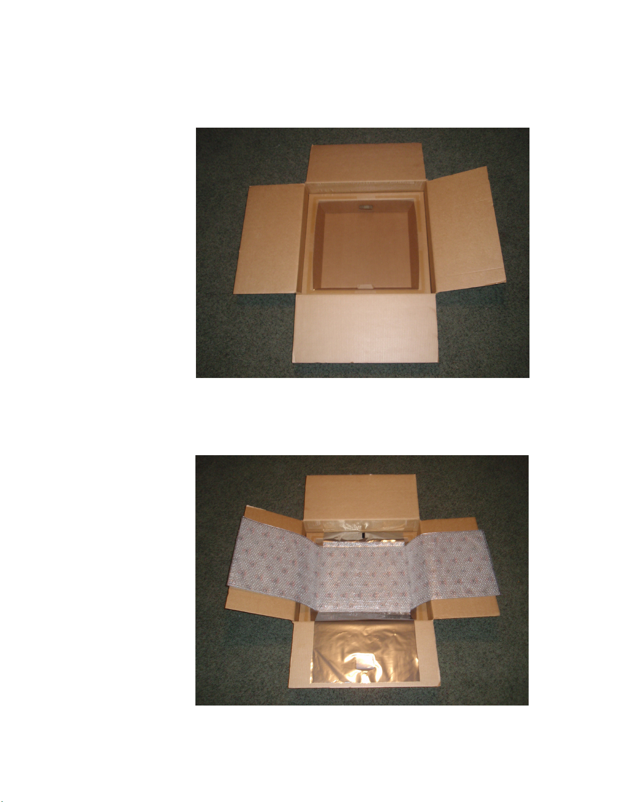
1. Locate the box in which the Branding Engine board(s) and software
were shipped.
2. Open the box and remove the contents.
The box contains two suspension trays and an anti-static bag which will be
used in the installation process. See Figure 13.
Maestro — Branding Engine Quick Start Guide 39
Page 40

Section 2 — Hardware Installation
Figure 13. Branding Engine Shipping Box
The suspension tray is designed to cushion and protect the processor board
while the Branding Engine mezzanine board is installed. As illustrated in
Figure 14, the suspension tray is a stiff cardboard frame with a strong
plastic suspension film covering the tray.
Figure 14. Shipping Box Suspension Tray
40 Maestro — Branding Engine Quick Start Guide
Page 41
Branding Engine Board Installation
3. Place one suspension tray in the box with the suspension film facing
upwards as shown in Figure 15.
Figure 15. Shipping Box with Suspension Tray Inserted
4. Open the velcro closure on the anti-static bag and open and position the
bag over the suspension tray as illustrated in Figure 16.
Figure 16. Anti-Static Bag Open On the Suspension Tray
Maestro — Branding Engine Quick Start Guide 41
Page 42

Section 2 — Hardware Installation
5. Remove the Maestro processor board from its frame and place it upside
down on the anti-static bag as shown in Figure 17.
Figure 17. Maestro Processor Board on Anti-Static Bag
The Branding Engine board front and back views are shown in Figure 18.
Figure 18. Branding Engine Board - Front and Back Views
Figure 19 shows the Maestro Processor board and indicates the mounting
location for the Branding Engine board(s).
42 Maestro — Branding Engine Quick Start Guide
Page 43

Figure 19. Branding Engine Mounting Location
Branding Engine Board Installation
With the board turned so the back side is facing up and the extractors and
compact flash slot at the bottom edge (see Figure 17), the Branding Engine
mounting locations are in the bottom right corner of the board.
Note The complete Branding Engine solution with support for still images, audio,
CG text, text crawls, animation sequences and motion video requires three
Branding Engine boards. The basic solution with support for still images and
audio files only requires just one Branding Engine board mounted in position
number one (1).
6. Align the connectors and screw hole on the Branding Engine board
with the connectors and screw post on the Maestro processor board and
press firmly to interlock the connectors.
7. Use the included mounting screw to fasten the Branding Engine board
in place on the Maestro Processor board.
Figure 20 illustrates a Branding Engine board installed in position number
one (1) on the Maestro Processor board.
Maestro — Branding Engine Quick Start Guide 43
Page 44

Section 2 — Hardware Installation
Figure 20. Branding Engine Board Installed on the Maestro Processor Board
Proceed to Branding Engine Hard Drive(s) Installation on page 45.
44 Maestro — Branding Engine Quick Start Guide
Page 45

Branding Engine Hard Drive(s) Installation
Branding Engine Hard Drive(s) Installation
Branding Engine storage is provided by one or more hard disk drives. As
illustrated in
on each Maestro channel processor board.
Figure 21. Branding Engine Disk Drives Installed
Figure 21, up to four 2.5 inch (6.35 cm) drives can be mounted
There are two separate PCI busses, each of which can support one (1) or
two (2) hard disk drives. The first PCI bus supports storage and playback
of still images, audio and CG text. The second PCI bus supports storage for
animation sequences and motion video.
Version 1.6 of Maestro supports Branding Engine stills and audio files only;
therefore, only the first PCI bus is utilized. When installing disk drives for
the basic Branding Engine, the first drive must be installed in the lower left
position labelled “Drive: ata0.” If a second drive is installed to support the
basic Branding Engine, it should be installed in the upper left position
labelled ‘Drive: ata1.”
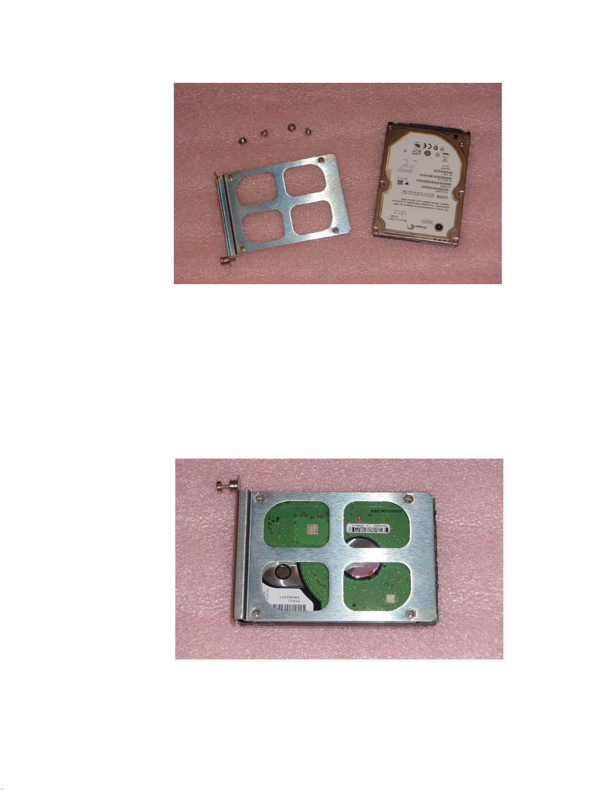
Figure 22 shows the hardware used in mounting the Branding Engine disk
drive in the drive cage.
Note If the hard disk drive was received from Grass Valley, the drive sled will
already be mounted on the drive. In this case, proceed directly to Step 4
Maestro — Branding Engine Quick Start Guide 45
Page 46
Section 2 — Hardware Installation
Figure 22. Branding Engine Disk Drive Mounting Hardware
To install a Branding Engine disk drive, do the following:
Note Steps 1-3 are necessary only if replacing the drive supplied by Grass Valley
with a different drive. In this case, the mounting sled must be removed from
the old drive and mounted on the new drive.
1. Position the hard drive with the circuit board side facing up.
2. Position the drive sled on the drive so that the four screw holes in the
sled are aligned with the screw holes in the drive. See Figure 23.
Figure 23. Drive Sled Aligned on Disk Drive
46 Maestro — Branding Engine Quick Start Guide
Page 47

Branding Engine Hard Drive(s) Installation
Note The drive sled face plate is positioned at the closed end of the drive. Make
sure the drive connectors at the back of the drive are not covered.
3. With the included screws, attach the drive sled to the disk drive.
The drive mounting sled properly attached to a disk drive is illustrated in
Figure 24
Figure 24. Mounting Sled Attached to Disk Drive
4. Insert the mounting sled and drive assembly into the desired slot in the
disk drive cage on the Maestro Processor board. Push gently to make
sure the drive connector and interface board connectors at the rear of
the drive cage are well connected.
Note If installing only one drive, it should be installed in the lower left slot (ata0).
5. Tighten the mounting screw on the sled to securely hold the disk drive
in the drive cage.
Figure 25 shows the drive assembly installed in the drive cage on the
Maestro Processor board.
Maestro — Branding Engine Quick Start Guide 47
Page 48

Section 2 — Hardware Installation
Figure 25. Drive Assembly Installed in Drive Cage
6. With the Branding Engine board mounted on the Maestro Processor
board and the disk drive(s) installed, carefully reinsert the Maestro
Processor board into the frame.
7. In the Deployment Center, verify that the board starts properly with no
errors.
As illustrated in Figure 26, “Started” will appear in the “Status” column if
the board loads with no errors.
48 Maestro — Branding Engine Quick Start Guide
Page 49

Figure 26. Maestro Processor Boards Started
Branding Engine Hard Drive(s) Installation
If any errors occur and the board fails to load after mounting the Branding
Engine hardware, make note of these errors and contact Grass Valley Technical Support.
Proceed to Mounting and Formatting Drives on page 50.
Maestro — Branding Engine Quick Start Guide 49
Page 50

Section 2 — Hardware Installation
Mounting and Formatting Drives
Hard drives installed in the drive cage must be mounted and formatted
before branding content can be copied to the drives. Drives received from
Grass Valley have been formatted and tested prior to shipment.
Note Installing a drive may be done with the Maestro Processor board installed in
the frame and running. There is no need to remove the board in order to
install a drive.
Mounting a Drive
Each drive has a push button for mounting the drive as illustrated in
Figure 27.
Figure 27. Branding Engine Drive Mount Buttons
To mount a drive, push the mount button associated with that drive.
If the drive mounts successfully, the mount LED (see Figure 28), for that
drive is illuminated.
50 Maestro — Branding Engine Quick Start Guide
Page 51

Mounting and Formatting Drives
Figure 28. Drive Mount and Activity LEDs
If the mounted drive was received from Grass Valley, proceed to Installing
the Content Gateway on page 54. Partitioning and formatting the drive is
only necessary if replacing a Grass Valley supplied drive.
Partitioning and Formatting a Drive
Note Partitioning and formatting a drive is necessary only if replacing a drive pro-
vided by Grass Valley. Drives received from Grass Valley have been partitioned, formatted and tested prior to shipment.
Once a drive has been installed and mounted, it must be partitioned and
formatted in order for the Content Gateway to create the necessary folders
and then copy the branding elements to those folders .
To partition and format a drive, do the following:
1. Initiate a Telnet session to the IP address of the Maestro Processor board
on which the drive is mounted.
2. At the prompt, type “devs” to display all devices.
All mounted drives will then appear in the list as illustrated in Figure 29.
Maestro — Branding Engine Quick Start Guide 51
Page 52

Section 2 — Hardware Installation
Figure 29. Maestro Processor Device List
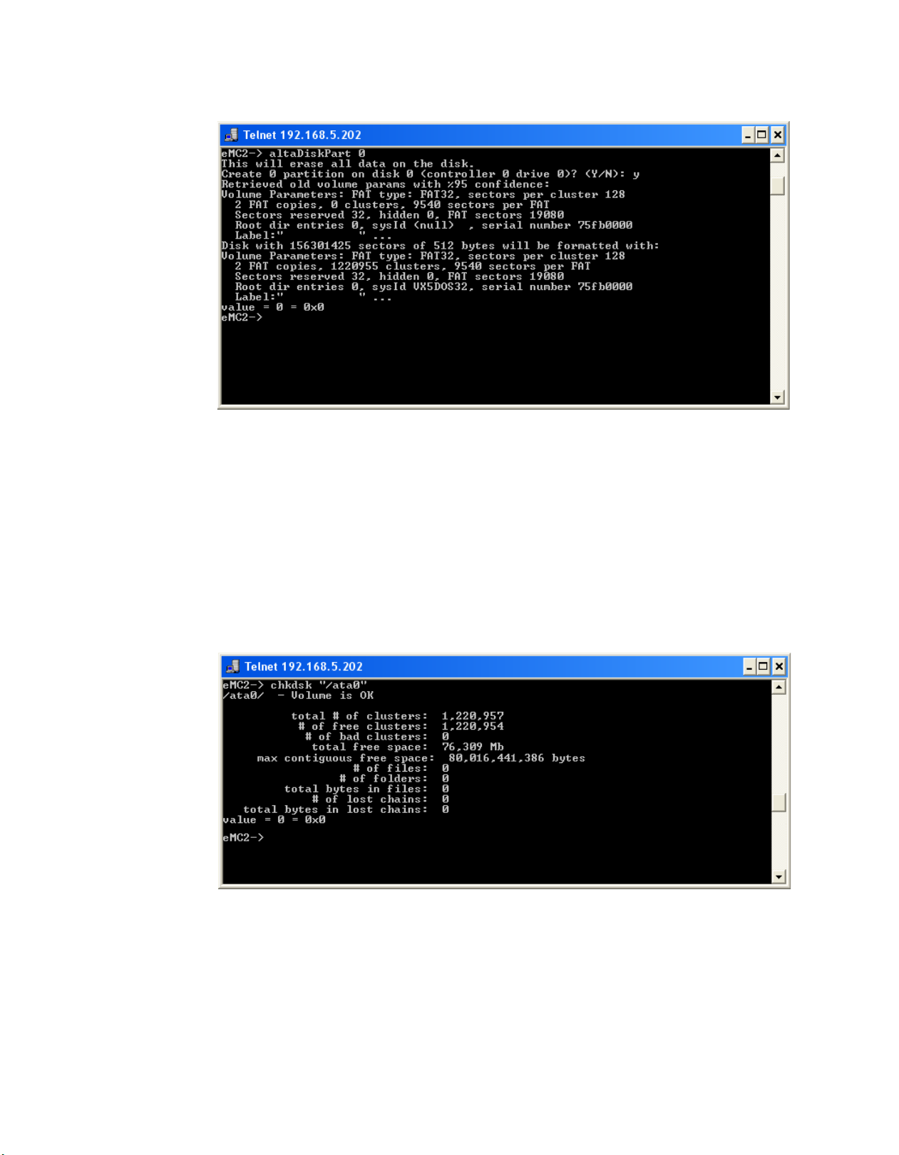
3. At the prompt, enter the command (without the quotation marks)
“altaDiskPart X’ where X is the ata disk number. Disk numbers can be
0-3.
Note The command is case sensitive and must be entered as shown above.
A confirmation prompt will appear. If this prompt does not appear, re-enter
the command.
4. Enter “y” at the confirmation prompt to proceed with partitioning and
formatting
When partitioning and formatting is complete, the status information is
then displayed. See Figure 30.
52 Maestro — Branding Engine Quick Start Guide
Page 53
Mounting and Formatting Drives
Figure 30. Disk Partitioning Command and Status
5. If desired, verify the partition by entering the following at the
command prompt:
chkdsk “/ataX” where X is the ata disk number (0-3) of the disk.
Note The quotation marks around the ata disk designator are required.
Verifying the partition may take a while to complete. After verification,
information similar to that in Figure 31 will be displayed.
Figure 31. Partition Verification Information
Note Disk verification may cause the Maestro Processor to temporarily lose com-
munications with the Deployment Center.
Maestro — Branding Engine Quick Start Guide 53
Page 54

Section 2 — Hardware Installation
Deployment PC
and
Content Gateway
House LAN
Branding Element Production
Maestro LAN
VPN Firewall
Maestro Facility and
Control LAN Switch
House LAN Switch
(Partial Representation)
Maestro channels
containing deployed
branding content
Installing the Content Gateway
The Content Gateway is one or more PCs and folders in which branding
elements are stored. These branding elements may be defined for use by
Maestro channels and deployed to those channels with the Maestro Config
uration Editor and Maestro Deployment Center applications. It is recommended that a single PC be used to host the Content Gateway; although, it
is possible to use more than one.
For simplicity, it may be desirable to install the Content Gateway on the
Maestro Deployment PC. The discussion which follows assumes the
Deployment PC is used as the Content Gateway.
Note Content Gateway folders may be installed on one or more PCs, including the
Deployment PC, if desired; however, to protect the Maestro LAN, all Content
Gateway PC(s) should be behind the VPN firewall as illustrated in Figure 32.
Figure 32 shows an example of the LAN configuration which connects the
Deployment PC and Content Gateway to the House LAN on which
branding element production takes place.
-
Figure 32. Branding Exchange Gateway LAN Configuration
54 Maestro — Branding Engine Quick Start Guide
Page 55

Installing the Content Gateway
Note The LAN configuration in Figure 32 is an example only. Please note that the
installation and configuration of the Content Gateway and the interfaces
between the Branding Element Production LAN and the Content Gateway
uses customer-supplied equipment which is not included with Maestro or the
Branding Engine hardware.
In order to minimize the impact to both the house branding element production network and the Maestro network, the Deployment/Content
Gateway PC is the only machine that has access to both the Branding
Element Production LAN and the Maestro LAN.
The Content Gateway require the configuration of a LAN separate from the
Maestro Facility and Control LANs. If the GUI control panel is also
installed on the Deployment PC, it will be necessary to add a third Network
Interface Card (NIC) to the Deployment PC/Content Gateway in order for
the Branding Element Production LAN to have access to the Content
Gateway for storing branding elements.
Note For simplicity, Grass Valley recommends the Belkin Gigabit USB 2.0 Network
Adapter (Belkin part number F5D5055 shown in Figure 33) as it can be added
easily without opening the PC. This hardware has been tested in a configuration similar to that illustrated in Figure 32.
Figure 33. Belkin Gigabit USB 2.0 Network Adapter
The VPN firewall protects the Deployment PC (or other PCs) on which the
Content Gateway resides and the Maestro LAN from unauthorized local or
remote access.
Note Grass Valley recommends the 3COM OfficeConnect Gigabit VPN Firewall
Appliance (3COM part number 3CREVF100-73). This hardware has been
tested in a configuration similar to that illustrated in Figure 32.
The 3COM OfficeConnect Gigabit VPN Firewall Appliance has two (2)
WAN ports and six (6) LAN ports as illustrated in Figure 34.
Maestro — Branding Engine Quick Start Guide 55
Page 56

Section 2 — Hardware Installation
Figure 34. 3COM OfficeConnect Gigabit VPN Firewall Ports
Connect the Deployment/Content Gateway PC, VPN Firewall and House
LAN as follows:
1. Connect the House LAN to the VPN Firewall WAN 1 port with a CAT6
Ethernet cable.
2. Attach the Gigabit USB NIC to a rear panel USB port on the
Deployment/Content Gateway PC.
Note Actual network performance is limited by the USB bus speed and traffic on
the USB bus.
3. Connect the Deployment/Content Gateway USB NIC to a VPN
Firewall LAN port with a CAT6 Ethernet cable.
Note The default IP address of the 3COM VPN Firewall appliance is 192.168.1.1. It
is configured as a DHCP server and will assign a 192.168.1.x address to the
the USB NIC. If you desire a different subnet range for the VPN Firewall,
consult the 3COM OfficeConnect documentation for instructions on changing
the default IP address and DHCP address assignment range.
Consult the 3COM OfficeConnect VPN Firewall documentation for
instructions on configuring the LAN/DMZ ports, firewall settings and
other features of interest in the VPN Firewall appliance.
Once the LAN connections and firewall are properly configured as illustrated in Figure 32, the Content Gateway may be installed and accessed
from the branding element production LAN.
To install the Content Gateway do the following:
1. On the Deployment/Content Gateway PC, create the folders in which
you wish to store branding content transferred from the branding
element production computers.
Note Depending on the number and size of branding elements you anticipate
storing and deploying to Maestro channels, if using the Deployment PC as the
Content Gateway, you may wish to install a separate hard drive specifically for
this purpose.
The folder structure in which branding elements are stored on the Content
Gateway is not fixed; Any folder structure that allows for the logical organization of branding elements and makes it easy to transfer them from the
56 Maestro — Branding Engine Quick Start Guide
Page 57

Installing the Content Gateway
production LAN to the Content Gateway can be used; however, the folder
structure illustrated in Figure 35 (or something similar) is recommended.
Figure 35. Content Gateway Folder Structure Example
2. Share the Content Gateway directories on the Deployment/Content
Gateway PC(s) so they are accessible on the network. To create a share
in Windows XP, do the following:
a. Select the top level Content Gateway folder in the Windows
Explorer folder view.
b. Right-click on the folder name and select “Sharing and Security”
from the menu.
The sharing properties dialog illustrated in Figure 36 appears.
Maestro — Branding Engine Quick Start Guide 57
Page 58

Section 2 — Hardware Installation
Figure 36. Content Gateway Shared Folder Settings
c. Enable the “Share this folder on the network” option by clicking in
the check box.
d. Enter a share name for the shared folder. This name will be used
when mapping a drive to the Content Gateway from computers on
the branding element production LAN.
Note Share names longer than 12 characters are not supported in Windows oper-
ating systems other than Windows XP and Windows Vista.
e. Enable the “Allow network users to change my files” option by
clicking in the check box.
f. Click the OK button to apply the share settings and close the dialog.
3. From the Branding Element Production computer(s) on the local
Branding Element Production LAN, map a drive to the shared drive/
directory on the Deployment/Content Gateway PC. To map a drive to
the shared directory, do the following:
a. From Windows Explorer, select Tools>Map Network Drive from the
menu bar.
The Map Network Drive dialog shown in Figure 37 appears.
58 Maestro — Branding Engine Quick Start Guide
Page 59

Installing the Content Gateway
Figure 37. Map Network Drive Dialog
b. From the Drive: drop-down list, select the drive letter you want to
map to the Content Gateway shared folder.
c. In the Folder: field enter the name of the computer that contains the
Content Gateway folders and the share name entered in Step 2. The
Browse... button may also be used to locate the desired computer
and shared folder.
Note The format is \\{computer name}\{share name} e.g. \\MaestroPC\ContentGW.
d. Check the “Reconnect at Logon” box if you wish to re-establish this
drive mapping each time you logon to the branding element
production computer.
e. Click the Finish button to map the drive to the shared Content
Gateway directory.
4. Copy all branding element files you wish to make available to Maestro
channels to the appropriate folders on the mapped Content Gateway
drive (drive X: in the example above).
Branding elements stored in the Content Gateway folders are configured
for use by Maestro channels in the next section. Proceed to Section 3-Content
Configuration.
Maestro — Branding Engine Quick Start Guide 59
Page 60

Section 2 — Hardware Installation
60 Maestro — Branding Engine Quick Start Guide
Page 61

Content Configuration
This section describes the process of making branding elements available
for use on Maestro channels. Before proceeding with the configuration and
deployment of branding elements, the following (as described in the pre
ceding sections) must be done:
• The Branding Engine mezzanine board and hard drive(s) must be properly installed on the Maestro Processor board.
• The Content Gateway must be installed.
• The Branding Elements must be stored in the Content Gateway.
Content Definition Table
Section 3
-
Branding elements to be used in Maestro are defined in the Configuration
Editor Branding Content Definition table as illustrated in Figure 38 and
Figure 39.
Note Multiple Content Definition tables may be created in order to accommodate
different video output standards or different content sets for different channels. Content definitions are not assigned directly to channels; however, they
contain the sources from which branding inputs are made available to a
Maestro channel.
Maestro — Branding Engine Quick Start Guide 61
Page 62

Section 3 — Content Configuration
Figure 38. Branding Content Definition Table - Part 1
Figure 39. Branding Content Definition Table - Part 2
Note The original images must be in the proper resolution, size and aspect ratio for
the intended usage in either an SD or HD channel. Maestro does not do any
resizing or aspect ratio conversion.
When defining branding content, the following information is entered in
the Content Definition table(s).
Source Name
Identifies the branding element. This name will appear in the Input table
source selection drop-down list.
62 Maestro — Branding Engine Quick Start Guide
Page 63

Content Definition Table
Source Type
Select the source type for the branding element from the drop-down list
containing the following selections
• Animation (supported in a future software release)
• Audio Voice Over
• CG Text (supported in a future software release)
• Still Image
• Text Crawl (supported in a future software release)
Select the appropriate type for the branding element being entered into the
Content Definition table.
Levels
Designates the Maestro level(s) on which the branding element will be
available. From the drop-down list, select the desired Maestro level(s)
Choices are video and audio 1-16. Click the
making the level selection(s).
OK button to close the list after
Update Mode
From the drop-down list, select the desired branding element update
mode. Choices are:
•Manual
Branding elements defined as “manual” are updated whenever a configuration is loaded that contains those elements or when the Update Now button
is clicked in the Deployment Center.
•Automatic
Branding elements defined as “automatic” are monitored automatically in
the Content Gateway and anytime the file is changed, it is automatically
ingested, converted to the proper format and deployed with no manual
intervention required.
Loop Mode
Specifies the play mode for audio files and animation clips. Select from the
drop-down list box one of the following:
• Loop
Plays the audio file for its entire length then loops back to the beginning
and plays it again. This is repeated until playback is stopped manually by
removing the source from air.
• Play Once
Plays the audio file through one time and ends playback when the end of
the file is reached.
Maestro — Branding Engine Quick Start Guide 63
Page 64

Section 3 — Content Configuration
Horizontal Position (%)
Designates the default horizontal position on the screen - expressed as a
percentage of the screen width - for the upper left corner of the branding
element. The default position may be changed manually once the branding
element is assigned to a keyer.
Vertical Position (%)
Designates the default vertical position on the screen - expressed as a percentage of the screen height - for the upper left corner of the branding element. The default position may be changed manually or through
automation once the branding element is assigned to a video keyer.
Opacity (%)
Designates the default opacity (transparency) of the branding element.
Fully transparent is 0% opacity. Completely opaque is 100% opacity. The
default opacity may be changed manually once the branding element is
assigned to a video keyer.
Note Any changes made to the default position and opacity will be saved in source
memory. Any time the source is assigned and active, it will have the position
and opacity values as defined in source memory.
Audio Ratio
Designates the default audio mix over ratio when an audio element is
assigned to an audio over mixer. For example, if 12 dB is selected as the
default, Program audio level will be reduced by 12 dB and Banding audio
will be inserted at normal playback level. The range 0 db to 24 db and +Inf
dB.
Note If the value “+Inf dB” is selected, infinite ratio adjustments are possible.
Font
Note Fonts are not used with the branding elements supported in this software ver-
sion. Fonts will be implemented in a future version that supports CG Text and
Text Crawls.
Source File
Specifies the source file location on the Content Gateway for the branding
element. The
Content Gateway.
... button is clicked to browse for the desired source file on the
Create Key
Generates an alpha (key) channel for the still image, if the “Create Key”
check box is selected. Ideally, still image branding elements should be
created with an alpha channel before being ingested in the Content
64 Maestro — Branding Engine Quick Start Guide
Page 65

Gateway. For elements that do not have an alpha channel, Maestro can
create one if this option is selected. If the ‘Create Key” option is not selected
and the branding element does not have a key channel, it will be presented
as is and may not appear correctly on air.
Content Input Table
After creating the desired Content Definition tables, one or more Content
Input tables may be created. The Content Input table contains the branding
elements that will be available as inputs in any Input table with which the
Content Input is associated.
When creating a Content Input table, the Content Definition table association is designated as illustrated in Figure 40.
Figure 40. Branding Content Input Table - Content Definition Association
Content Input Table
Branding elements defined in the Content Definition table are added to the
Content Input table as illustrated in Figure 41.
Maestro — Branding Engine Quick Start Guide 65
Page 66

Section 3 — Content Configuration
Figure 41. Branding Content Input Table
The Content Input table is a way of “filtering” all available branding elements and designating only certain ones to be available as channel inputs.
Input Table
The final step in making branding elements available to Maestro channels
is to define them in the Input table.
To add branding elements to the Input table, a Content Input table is first
associated with the Input table as illustrated in Figure 42.
66 Maestro — Branding Engine Quick Start Guide
Page 67

Figure 42. Input Table - Content Input Table Association
Input Table
Figure 43 shows an example of an Input table with branding elements
defined as inputs.
Maestro — Branding Engine Quick Start Guide 67
Page 68

Section 3 — Content Configuration
Figure 43. Input Table with Branding Elements Added
Branding elements are entered into the input table in the same manner as
routed (external) or direct connect sources. When a branding element
source is selected from the drop-down list, it is identified as such with the
word (Content) following the source name. See Figure 44 for an example.
Figure 44. Branding Content Input Selection
68 Maestro — Branding Engine Quick Start Guide
Page 69

Input Table
Branding elements are considered “Internal” sources. They are stored on
the Branding Engine hard drive(s) located on the Maestro channel processor board. A cable connected to a rear panel input is not required to
access the source.
When a branding element is added to the Input table, the video and audio
sources are highlighted in green (see Figure 44) to indicate they are Internal
sources.
Note Highlighting of sources in colors that designate the source type is active only
if the “Enable source type color coding” option is selected in the Input table.
See Figure 44.
Only the branding elements defined in the Input table will be deployed to
and be available on the channel(s) which utilize a particular Input table.
The presence of the branding element in the Branding Content tables does
not necessarily result in that element being available to any Maestro channels. The Input table source definitions make that determination.
Save and compile the configuration with the branding content definition.
Proceed to Section 4-Deploy and Verify Content.
Maestro — Branding Engine Quick Start Guide 69
Page 70

Section 3 — Content Configuration
70 Maestro — Branding Engine Quick Start Guide
Page 71

Section 4
Deploy and Verify Content
This section describes the process of deploying configured branding elements to Maestro channels, verifying that they can be assigned to video
keyers and audio over mixers and that they display and playout as desired
on air.
Branding Element Deployment
To deploy a configuration that contains branding content definitions to a
Maestro channel, do the following:
1. Open the Deployment Center application on the Deployment PC.
2. In the Configuration section, select the desired configuration file from
the File drop-down list. See Figure 45.
Note Only one of the configurations highlighted in green should be selected. Those
configurations not highlighted in green have not been compiled with the
current software version and will not contain branding definitions. Only the
current software version (1.6.0) supports branding elements.
Maestro — Branding Engine Quick Start Guide 71
Page 72

Section 4 — Deploy and Verify Content
Figure 45. Configuration File Selection
3. Click the Update Only button.
This will download the selected configuration to all components defined in
the Maestro network; however, will not apply (activate) this configuration.
4. Click on one of the Maestro channel processors to select just that
channel. Make sure that only the selected channel is highlighted.
Note Before selecting a channel processor, you may need to first click the Unselect
All button if other Maestro network components are already selected.
5. Click the Apply Pending button to apply the configuration to only the
selected Maestro channel.
If there are any errors, note these errors and contact Grass Valley support
for assistance.
72 Maestro — Branding Engine Quick Start Guide
Page 73

Verify Branding Element Deployment
To verify the deployment of branding elements to the selected Maestro
channel do the following:
1. With the channel selected, verify that the branding elements were
properly deployed to the Maestro channel by clicking the
button as illustrated in Figure 46.
Figure 46. Deployment Center - Show Contents
Verify Branding Element Deployment
Show Contents
When the Show Contents button is clicked, the Branding Engine Content
widow shown in Figure 47 appears.
Note Depending on the number of branding elements deployed to the board, it may
be several minutes before this window appears.
Maestro — Branding Engine Quick Start Guide 73
Page 74

Section 4 — Deploy and Verify Content
Figure 47. Branding Engine Contents
2. If desired, branding elements may be manually updated, regardless of
the Manual/Automatic (Dynamic) setting, by selecting the desired
elements and clicking the
Update Now button as illustrated in Figure 48.
Figure 48. Select and Update Branding Elements
Note Elements are selected by clicking the far left column of the element to be
selected. Multiple elements may be selected by holding down the [CTRL] key
while clicking on the select column.
3. If the branding content appears to have deployed properly on the
tested channel, click the
configuration to all components in the Maestro network.
Update and Apply button to deploy the
74 Maestro — Branding Engine Quick Start Guide
Page 75

Verify Branding Element Assignment
To verify that deployed branding content can be assigned properly to video
keyers or audio over mixers, do the following:
1. On a control panel Source Assignment panel (hardware or GUI) press
Send button.
the
2. Select the category button to which a still image or audio mix over
branding source has been assigned.
3. Enter the source number that designates the desired source.
Note As an example, in Figure 43 on page 68, “SMPTE Bars” is source number 11
in the Logo category.
4. Press any PST button on the Keyer or Audio panel (depending on the
source type you wish to assign) that is illuminated in green to assign the
selected source to that button.
The specified mnemonic for the selected source appears in the PGM LCD
button.
Verify Branding Element Assignment
5. Press the appropriate PST button to activate the source on the PST
monitor.
6. Verify the presence of a still image source on the PST monitor or the
presence of an audio over source by selecting the appropriate audio
over mixer as the monitor point in the Audio sub-panel.
Maestro — Branding Engine Quick Start Guide 75
Page 76

Section 4 — Deploy and Verify Content
76 Maestro — Branding Engine Quick Start Guide
Page 77

Index
B
branding element assignment 75
branding element deployment 71
branding elements in input table 66
branding engine board installation 39
branding engine hard drive installation 45
C
content configuration 61
content definition table 61
content gateway defined 54
content gateway installation 54
content input table 65
D
deployment verification 73
documentation online 5
drive formatting 51
drive mounting 50
drive partitioning 51
M
mount drive 50
O
online documentation 5
S
software download from web 5
software upgrade 19
U
upgrade requirements 19
upgrade software 19
W
web site documentation 5
web site FAQ database 5
web site Grass Valley 5
web site software download 5
F
FAQ database 5
formatting a drive 51
frequently asked questions 5
G
Grass Valley web site 5
I
input table 66
installation
branding engine mezzanine
content gateway 54
hard drive(s) 45
Maestro — Branding Engine Quick Start Guide 77
39
Page 78

Index
78 Maestro — Branding Engine Quick Start Guide
 Loading...