

GRASS VALLEY MAESTRO 1.5 - RELEASE NOTES, MAESTRO 1.500 - RELEASE NOTES 2-12-2008, Maestro Release Note
Page 1
Maestro
MULTI-FORMAT MASTER CONTROL
Release Notes
SOFTWARE VERSION 1.500
071850605
February 12, 2008
Page 2

Affiliate with the N.V. KEMA in The Netherlands
CERTIFICATE
Certificate Number: 510040.001
The Quality System of:
Grass Valley, Inc.
400 Providence Mine Road
Nevada City, CA 95945
United States
15655 SW Greystone Ct.
Beaverton, OR 97006
United States
10 Presidential Way
rd
3
Floor, Suite 300
Woburn, MA 01801
United States
Nederland B.V.
4800 RP BREDA
The Netherlands
Technopole Brest Iroise
CS 73808
29238 Brest Cedex 3
France
7140 Baymeadows Way
Suite 101
Jacksonville, FL 32256
United States
Weiterstadt, Germany
Brunnenweg 9
D-64331 Weiterstadt
Germany
17 rue du Petit Albi-BP 8244
95801 Cergy Pontoise
Cergy, France
Rennes, France
Rue du Clos Courtel
Cesson-Sevigne, Cedex
France
2300 South Decker Lake Blvd.
Salt Lake City, UT 84119
United States
Including its implementation, meets the requirements of the standard:
ISO 9001:2000
Scope:
The design, manufacture and support of video hardware and software products and
related systems.
This Certificate is valid until: June 14, 2009
This Certificate is valid as of: August 30, 2006
Certified for the first time: June 14, 2000
H. Pierre Sallé
President
KEMA-Registered Quality
The method of operation for quality certification is defined in the KEMA General Terms
And Conditions For Quality And Environmental Management Systems Certifications.
Integral publication of this certificate is allowed.
KEMA-Registered Quality, Inc.
4377 County Line Road
Chalfont, PA 18914
Ph: (215)997-4519
Fax: (215)997-3809
CRT 001 073004
Accredited By:
ANAB
Page 3
Maestro
MULTI-FORMAT MASTER CONTROL
Release Notes
SOFTWARE VERSION 1.500
071850605
February 12, 2008
Page 4
Contacting Grass Valley
International
Support Centers
Local Support
Centers
(available
during normal
business hours)
France
24 x 7
Australia and New Zealand: +61 1300 721 495 Central/South America: +55 11 5509 3443
Middle East: +971 4 299 64 40 Near East and Africa: +800 8080 2020 or +33 1 48 25 20 20
Europe
+800 8080 2020 or +33 1 48 25 20 20
+800 8080 2020 or +33 1 48 25 20 20
Hong Kong, Taiwan, Korea, Macau: +852 2531 3058 Indian Subcontinent: +91 22 24933476
Asia
Southeast Asia/Malaysia: +603 7805 3884 Southeast Asia/Singapore: +65 6379 1313
China: +861 0660 159 450 Japan: +81 3 5484 6868
Belarus, Russia, Tadzikistan, Ukraine, Uzbekistan: +7 095 2580924 225 Switzerland: +41 1 487 80 02
S. Europe/Italy-Roma: +39 06 87 20 35 28 -Milan: +39 02 48 41 46 58 S. Europe/Spain: +34 91 512 03 50
Benelux/Belgium: +32 (0) 2 334 90 30 Benelux/Netherlands: +31 (0) 35 62 38 42 1 N. Europe: +45 45 96 88 70
Germany, Austria, Eastern Europe: +49 6150 104 444 UK, Ireland, Israel: +44 118 923 0499
Copyright © Grass Valley. All rights reserved.
This product may be covered by one or more U.S. and foreign patents.
United States/Canada
24 x 7
+1 800 547 8949 or +1 530 478 4148
Grass Valley Web Site
The www.thomsongrassvalley.com web site offers the following:
Online User Documentation — Current versions of product catalogs, brochures,
data sheets, ordering guides, planning guides, manuals, and release notes
in .pdf format can be downloaded.
FAQ Database — Solutions to problems and troubleshooting efforts can be
found by searching our Frequently Asked Questions (FAQ) database.
Software Downloads — Download software updates, drivers, and patches.
4 Maestro — Release Notes
Page 5

Contents
Maestro Release Notes. . . . . . . . . . . . . . . . . . . . . . . . . . . . . . . . . . . . . . . . . . . . . . . . . . . 7
Purpose . . . . . . . . . . . . . . . . . . . . . . . . . . . . . . . . . . . . . . . . . . . . . . . . . . . . . . . . . . . . . . . 7
Features Modified From Previous Software Versions. . . . . . . . . . . . . . . . . . . . . . . . 7
Features Added . . . . . . . . . . . . . . . . . . . . . . . . . . . . . . . . . . . . . . . . . . . . . . . . . . . . . . . . 8
Interoperability Requirements . . . . . . . . . . . . . . . . . . . . . . . . . . . . . . . . . . . . . . . . . . . 8
Upgrade Requirements . . . . . . . . . . . . . . . . . . . . . . . . . . . . . . . . . . . . . . . . . . . . . . . . . 9
Caveats . . . . . . . . . . . . . . . . . . . . . . . . . . . . . . . . . . . . . . . . . . . . . . . . . . . . . . . . . . . . . . . 9
Materials Supplied . . . . . . . . . . . . . . . . . . . . . . . . . . . . . . . . . . . . . . . . . . . . . . . . . . . . 10
Additional Documentation . . . . . . . . . . . . . . . . . . . . . . . . . . . . . . . . . . . . . . . . . . . . . 10
Release Notes/Addendums. . . . . . . . . . . . . . . . . . . . . . . . . . . . . . . . . . . . . . . . . . . 10
Manuals. . . . . . . . . . . . . . . . . . . . . . . . . . . . . . . . . . . . . . . . . . . . . . . . . . . . . . . . . . . . 10
Engineering Change Orders . . . . . . . . . . . . . . . . . . . . . . . . . . . . . . . . . . . . . . . . . . 11
Monitor Follow Operation. . . . . . . . . . . . . . . . . . . . . . . . . . . . . . . . . . . . . . . . . . . . . . 12
Monitor Follow Configuration . . . . . . . . . . . . . . . . . . . . . . . . . . . . . . . . . . . . . . . . 13
Monitor Follow Table . . . . . . . . . . . . . . . . . . . . . . . . . . . . . . . . . . . . . . . . . . . . . . 13
Monitor Follow Configuration Examples . . . . . . . . . . . . . . . . . . . . . . . . . . . . . 15
Channel Setup Table . . . . . . . . . . . . . . . . . . . . . . . . . . . . . . . . . . . . . . . . . . . . . . . 17
Aux Monitor Point in Audio Control Panel . . . . . . . . . . . . . . . . . . . . . . . . . . . . . . . 18
Audio Monitor Source Tally . . . . . . . . . . . . . . . . . . . . . . . . . . . . . . . . . . . . . . . . . . . . 19
Audio/Video Breakaway. . . . . . . . . . . . . . . . . . . . . . . . . . . . . . . . . . . . . . . . . . . . . . . 22
Video Breakaway. . . . . . . . . . . . . . . . . . . . . . . . . . . . . . . . . . . . . . . . . . . . . . . . . . . . 23
Audio Breakaway . . . . . . . . . . . . . . . . . . . . . . . . . . . . . . . . . . . . . . . . . . . . . . . . . . . 24
Audio Breakaway - All Audio Groups From a Single Source. . . . . . . . . . . . . 25
Audio Breakaway - One Or More Audio Groups From Multiple Sources . . 26
Dynamic Channel Mapping . . . . . . . . . . . . . . . . . . . . . . . . . . . . . . . . . . . . . . . . . . . . 32
Channel Mapping Process . . . . . . . . . . . . . . . . . . . . . . . . . . . . . . . . . . . . . . . . . . . . 35
Audio Output Group Substitution . . . . . . . . . . . . . . . . . . . . . . . . . . . . . . . . . . . 36
Un-Mapping Channels . . . . . . . . . . . . . . . . . . . . . . . . . . . . . . . . . . . . . . . . . . . . . . . 38
Battery Charging Status . . . . . . . . . . . . . . . . . . . . . . . . . . . . . . . . . . . . . . . . . . . . . . . . 39
Software Upgrade Procedure . . . . . . . . . . . . . . . . . . . . . . . . . . . . . . . . . . . . . . . . . . . 40
Maestro Deployment PC . . . . . . . . . . . . . . . . . . . . . . . . . . . . . . . . . . . . . . . . . . . . . 40
Requirements . . . . . . . . . . . . . . . . . . . . . . . . . . . . . . . . . . . . . . . . . . . . . . . . . . . . . 40
Installing the Maestro Software Package . . . . . . . . . . . . . . . . . . . . . . . . . . . . . . 41
Manually Removing the Maestro Jupiter Router Service Software . . . . . . . . 45
Re-compiling the Configuration File. . . . . . . . . . . . . . . . . . . . . . . . . . . . . . . . . . 46
Updating the System Configuration and Software. . . . . . . . . . . . . . . . . . . . . . 47
Checking the Boot ROM Versions. . . . . . . . . . . . . . . . . . . . . . . . . . . . . . . . . . . . 51
Checking the GUI Control Panel for Proper LAN Settings. . . . . . . . . . . . . . . . . 53
Updating FPGAs/CPLDs. . . . . . . . . . . . . . . . . . . . . . . . . . . . . . . . . . . . . . . . . . . . . 54
Maestro — Release Notes 5
Page 6

Contents
6 Maestro — Release Notes
Page 7

Ver sion 1.500
Maestro Release Notes
Purpose
This document provides software installation instructions for the 1.500
software release of the Maestro Master Control System. This release provides additional functionality and corrects certain software problems associated with the previous releases. However, some functions are net yet
available, as noted in the separate v1.500 Release Notes Addendum. The
Release Notes Addendum also provides a list of software corrections
included with this release.
February 12, 2008
Features Modified From Previous Software Versions
• Monitor Follow configuration has changed substantially from its introduction in version 1.3. Although the manner in which the feature operates has not changed, the configuration of Monitor Follow is much
more flexible compared to its implementation in software version 1.3.
See page 12 for details.
Note The Monitor Follow configuration discussion in this document supersedes
the Monitor Follow configuration discussion on pages 65-67 in the Maestro
1.3 Release Notes. Beginning with software release 1.4, Monitor Follow operates as documented in these release notes.
• Responses from Maestro to automation commands now use Command
ID Matching. Previously, the Command ID was set to “1” or consecutive numbers starting with “1” when returning multiple responses.
With version 1.5, the Command ID responses are matched to the original automation command. Since the initial release of the automation
protocol, Command ID Matching has been planned and has now been
implemented.
• Automation can now assign a source to a keyer even if there is already
a source assigned to that keyer and that keyer is preset for the next transition.
Maestro — Release Notes 7
Page 8

Version 1.500
Features Added
• Aux Monitor Point in Audio Control Panel; See page 18 for details.
• Audio Monitor Source Tally; See page 19 for details.
• Audio/Video Breakaway; See page 22 for details.
• Dynamic Channel Mapping; See page 32 for details.
• Battery Charging Status in Deployment Center; See page 39 for details.
• The following automation commands have been added:
MAESTRO_AUDIO_MIXER_CHANNEL_MAPPING
MAESTRO_AUDIO_MIXER_CHANNEL_DEFAULT_MAPPING
MAESTRO_AUDIO_MIXER_CHANNEL_UNMAPPING
MAESTRO_BACKGROUND_AUDIO_CHANNEL_MAPPING
MAESTRO_BACKGROUND_AUDIO_CHANNEL_UNMAPPING
MAESTRO_BACKGROUND_AUDIO_CHANNEL_DEFAULT_MAPPING
• “Auxiliary” is now a possible selection for the <destInputBus> argument for the following automation commands:
MAESTRO_BACKGROUND_SELECT
MAESTRO_BACKGROUND_AUDIO_GAIN
MAESTRO_BACKGROUND_STEREO_MODE
MAESTRO_BACKGROUND_AUDIO_BALANCE
MAESTRO_KEYER_SELECT
See the Maestro Automation Interface Protocol Technical Reference
Manual, v1.5 for additional details concerning additions to or changes
in the automation commands.
Interoperability Requirements
• Encore router control system version 1.7 or newer, or
• Jupiter router control system version 4.2 or newer when using ESSwitch on a VM control system, or
• Jupiter router control system version 7.3 or newer when using ESSwitch on a CM control system, or
• Jupiter router control system 7.5.0 or newer when using ES-LAN on a
CM control system
8 Maestro — Release Notes
Page 9

Upgrade Requirements
• The previously installed version of Maestro software must be unin-
stalled before installing the v1.5 software.
•The Software Upgrade Procedure on page 40 must be followed as
described.
• Systems that are being upgraded from version 1.3 or earlier may
require special Telnet procedures to complete the update. Because of
this possibility, installers should obtain a copy of Field Modification
Note 075079500, Backup Battery, CP Server, and CP FPGA Telnet Upgrade
before proceeding.
Caveats
• Network issues are presently the most common cause of problems at
customer sites. Network installation and configuration must follow
Grass Valley recommendations. Please refer to “VLAN Network
Topology” section in the v1.3 Release Notes (part number: 071850603).
Upgrade Requirements
• All Maestro processors connected to the same Maestro deployment PC
and comprising a single system (all processors interconnected via the
same facility and control LANs) must have the same software version
and configuration deployed to them. Having disparate software versions/configurations deployed within a single system is not supported
and may result in communication/configuration incompatibilities and
system failure.
Maestro — Release Notes 9
Page 10

Version 1.500
Materials Supplied
Table 1. MAE-HD-SW Bill of Materials
Quantity Description Part number
Table 2. MAE-SD-SW Bill of Materials
Quantity Description Part number
MAE-HD-SW Maestro Software Upgrade
1
1 Release Notes, Maestro v1.500 071850605
1 Release Notes Addendum, Maestro v1.500 071850705
1 Maestro Documentation CD 071851705
1
1 Release Notes, Maestro v1.500 071850605
1 Release Notes Addendum, Maestro v1.500 071850705
1 Maestro Documentation CD 071851705
CDROM, Maestro HD Software Program,
v1.500 (1.500.2841.950)
MAE-SD-SW Maestro Software Upgrade
CDROM, Maestro SD Software Program,
v1.500 (1.500.2841.950)
063825805
063825905
Additional Documentation
Release Notes/Addendums
Maestro v1.500 Release Notes Addendum 071850705*
Maestro v1.4 Release Notes 071850604 and Release Notes Addendum
071850704*
Maestro v1.3 Release Notes 071850603 and Release Notes Addendum
071850703*
Maestro v1.2 Release Notes 071850602 and Release Notes Addendum
071850702*
Maestro v1.1 Release Notes 071850601 and Release Notes Addendum
071850701*
Manuals
Maestro Installation Planning Guide, 0718384xx*
Maestro Installation and Service Manual, 0718423xx*
Maestro User Manual, 0718482xx*
10 Maestro — Release Notes
Page 11

Note The above manuals are presently being revised to include v1.3, v1.4 and v1.5
enhancements.
Maestro Automation Interface Protocol Technical Reference Manual,
0718472xx*
Concerto Multi-format Router Instruction Manual, 0718138xx†
Encore Installation and Service Manual, 0718103xx†
Jupiter CM-4000 Installation and Operating Manual, 0718261xx†
Jupiter VM-3000 Installation and Operating Manual, 0718305xx†
Sonata Series Planning and Installation Manual, 0718609xx
Engineering Change Orders
ECO 334Q, Maestro v1.5 HD/SD software
Additional Documentation
*A copy of this publication is provided on the documentation CD supplied with this release.
†A copy of this publication is provided on the Router Products documentation CD supplied with this
release.
Maestro — Release Notes 11
Page 12
Version 1.500
PGM
PST
Clean Feed
Network
Off-Air RTN
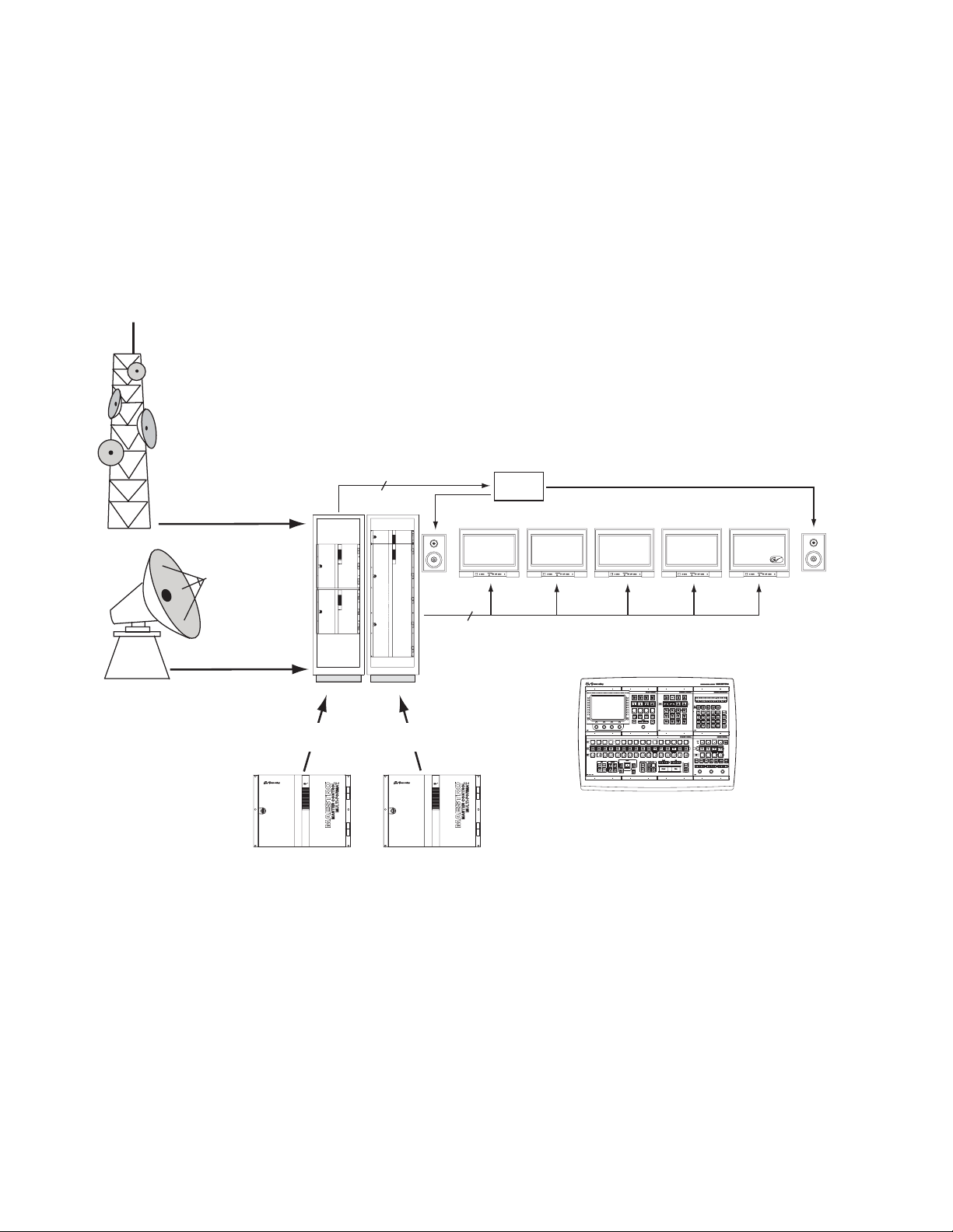
Monitor Follow Operation
In multi-processor (multi-channel) systems, the control room monitors can
now switch automatically to the channel being controlled by the control
panel. In the example shown in Figure 1, the operator is controlling eight
Maestro channels from a single hardware control panel. During monitor
follow operation, the monitor outputs of the channel being controlled are
automatically switched to the control room monitors.
Figure 1. Monitor Follow Operation
Off-Air Return
Video
audio
router
Network Programming
audio (Mon Out) signals for each channel
Channels 1-4 Channels 5-8
1 stereo pair
and
Video (PGM, PST, Clean Feed) and
5 video
Off-Air RTN
D-to-A
converter
Network
Clean Feed
Maestro Control Panel
PST
PGM
Although this example shows a control room equipped with stereo monitors, more speakers can be added (e.g., to allow Dolby 5.1 monitoring).
12 Maestro — Release Notes
Page 13
Monitor Follow Configuration
Monitor Follow operation is configured using the Monitor Follow table in
the Input/Output Sets group (“4th Step”) in the Maestro Configuration
Editor.
Monitor Follow Table
This table is used to describe the connections between matrix router inputs
and matrix router outputs when a channel delegation operation is performed from the control panel at the specified IP Address. Any router input
may be switched to any router output. These router inputs do not necessarily need to be connected to Maestro outputs although many of them will
be Maestro-related as in the examples below.
A separate table must be created for each channel (i.e., for each Maestro
Processor). Each table is given a name and assigned to a channel using the
Channel Setup table. The figures below represent two monitor follow
tables, one named SD-MonFllw which will be assigned to the channel
“WXYZ-SD” and another named HD-MonFllw which will be assigned to
the channel “WXYZ-HD.”
Monitor Follow Operation
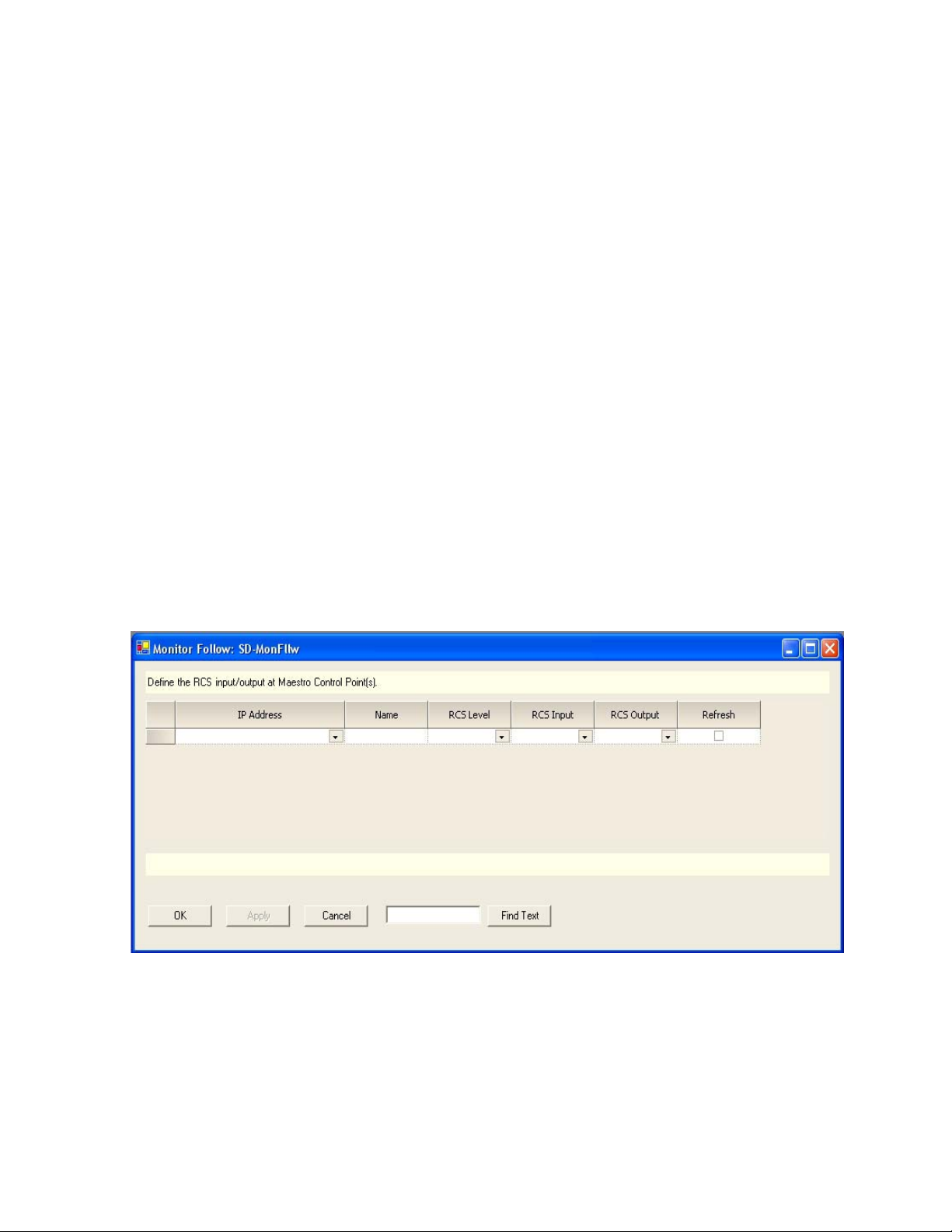
Figure 2 shows a new Monitor Follow table. An explanation of the table
entries appears below the table.
Figure 2. Monitor Follow Table
IP Address
The IP address of the control panel (hardware control panel or GUI PC
panel server card) from which channel delegation operations may be performed which should cause monitor follow router switches. The source for
the available selections is the Network Description table.
Maestro — Release Notes 13
Page 14

Version 1.500
Name
A user-specified name for a router input/router output pair to be switched
when a channel delegation operation is performed. Some examples are
PGM, PST, Off-air Return, etc. Any name is valid but it should describe the
source being directed to the monitors.
RCS Level
Router Control System (RCS) Level. This is the router level which contains
the router inputs and router outputs which will be switched when a
channel delegation operation is performed from the device at the specified
IP address. The RCS Level is selected from a list of all router levels defined
in the router control system and made available for use in Maestro.
RCS Input
A named router input (as defined in the selected Router Control System
Level) to which the source to be switched to the desired monitor is connected.
RCS Output
A named router output (as defined in the selected Router Control System
Level) which is connected to the monitor to which the designated source
input should be switched. This switch will take place when a channel delegation operation is performed.
Refresh
If this box is checked, the router inputs and outputs will be refreshed
approximately every 15 seconds and the designated routes will be re-established if they have changed.
Note If post-delegation operator control of what is routed to the monitors is
desired, this box should not be checked. With the box unchecked, a routing
of monitor outputs as defined in the Monitor Follow table would take place on
initial channel delegation; however, the operator could perform manual
routes to the monitor outputs after the delegation operation. Maestro would
only re-establish the Monitor Follow configured routes upon execution of
another channel delegation operation.
14 Maestro — Release Notes
Page 15
Monitor Follow Configuration Examples
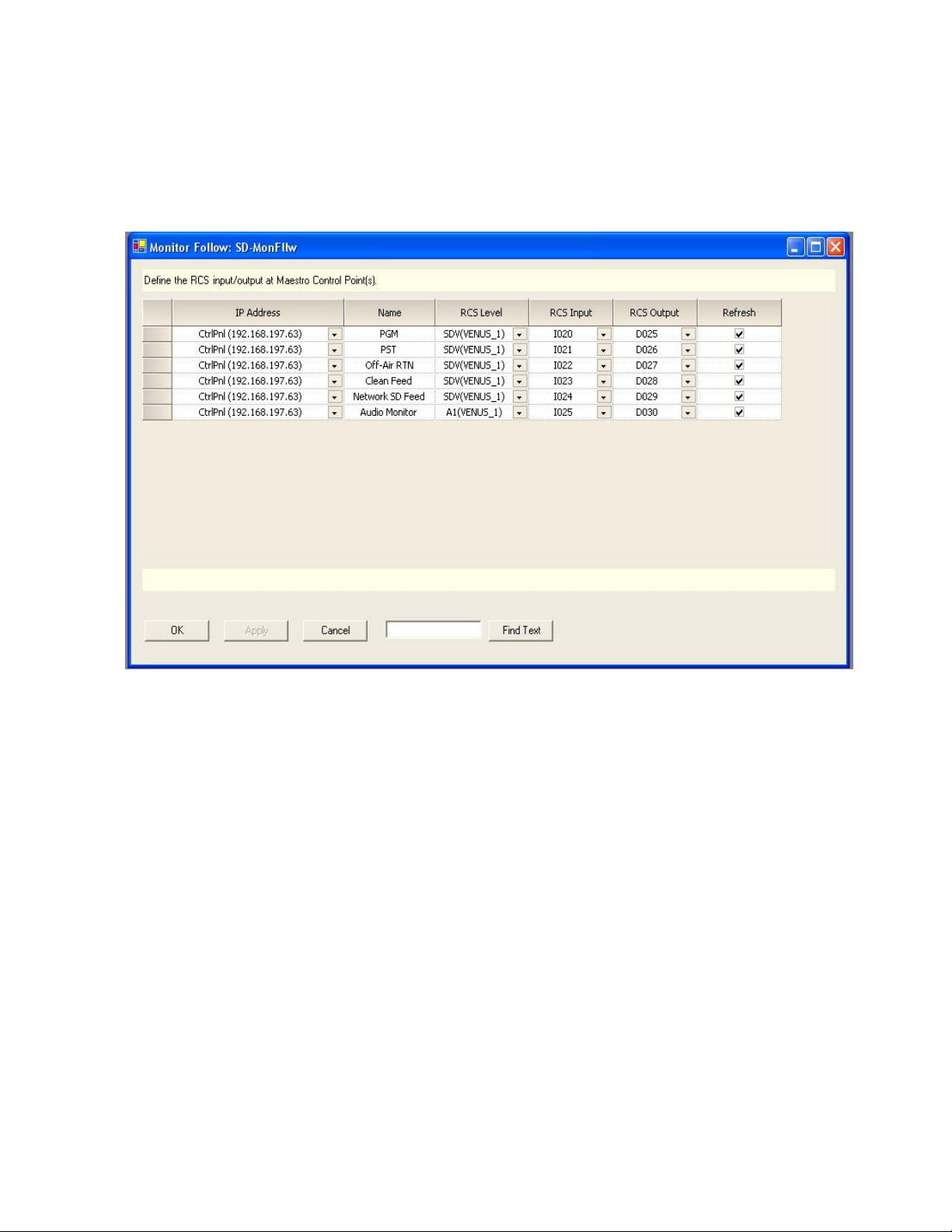
Figure 3 shows a sample Monitor Follow configuration for an SD channel
with stereo audio.
Figure 3. “SD” Channel Monitor Follow Configuration
Monitor Follow Operation
In Figure 3 sources defined as PGM, PST, Off-Air RTN, Clean Feed,
Network SD Feed and Audio Monitor are switched to the Master Control
room video and audio monitors when the channel “WXYZ-SD” is under
the control of the control panel at IP address 192.168.197.63. PGM, PST and
Clean Feed video as well as Audio Monitor are output from the SD Maestro
channel. Off-Air Return and SD Network Feeds are not Maestro outputs;
however they can be switched to the monitors whenever the “WXYZ-SD”
channel is the active channel on the control panel.
The first entry in SD-MonFllw table describes the following actions, physical connections and result (assuming this table is the assigned Monitor
Follow table for the channel “WXYZ-SD”):
• When the control panel with IP address 192.168.197.63 takes control of
the channel “WXYZ-SD” the router will automatically perform the
switches defined in this row.
• The PGM output on the Maestro rear panel for the channel “WXYZ-SD”
is wired to the router input labelled I020 on the SDV level.
Maestro — Release Notes 15
Page 16
Version 1.500
• Input I020 is switched to output D025 (also on the SDV level) which is
wired to the PGM video monitor in the master control room.
• The video source currently active on the PGM bus of the Maestro
“WXYZ-SD” channel thus appears on the PGM monitor in the master
control room.
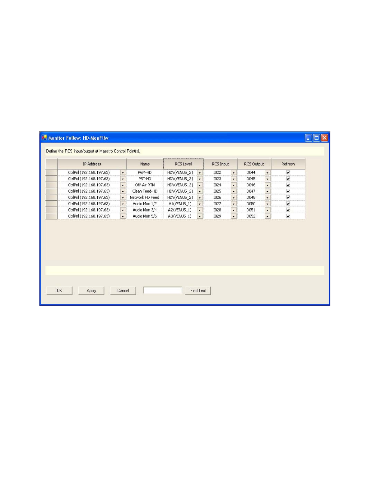
Figure 4 shows a sample configuration for an HD channel with discrete 5.1
surround audio.
Figure 4. “HD” Channel Monitor Follow Configuration
In Figure 4 sources defined as PGM HD, PST HD, Off-Air RTN, Clean Feed
HD, Network HD Feed and Audio Mon 1/2, Audio Mon 3/4 and Audio
Mon 5/6 are switched to the Master Control room video and audio monitors when the channel “WXYZ-HD” is controlled by the control panel at IP
address 192.168.197.63. PGM HD, PST HD and Clean Feed HD video as
well as three AES audio pairs (for 5.1 surround sound) are output from the
HD Maestro channel. Off-Air Return and HD Network Feeds are not
Maestro outputs; however they are switched to the monitors whenever the
channel “WXYZ-HD” is selected from the control panel.
16 Maestro — Release Notes
Page 17
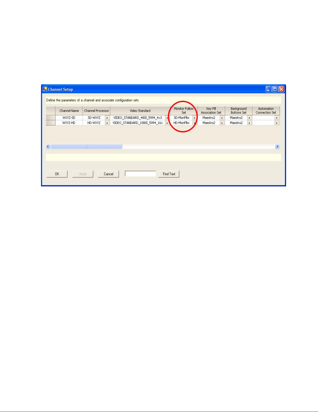
Channel Setup Table
After a Monitor Follow table has been created for each channel, use the
Channel Setup table to assign the tables to the appropriate channels as seen
in Figure 5.
Figure 5. Channel Setup Table
Monitor Follow Operation
Note The Monitor Follow Set designation appears further into the Channel Setup
table than shown here. When designating a Monitor Follow Set to be used for
a particular channel, use the horizontal scroll bar until you find the Monitor
Follow Set column.
Maestro — Release Notes 17
Page 18
Version 1.500
Ø
Main
C
Lfe
LsR
1
Ø
Lt
Rt
Ø
D S
Sp
Aux Monitor Point in Audio Control Panel
The audio control panel allows the operator to select which audio source is
routed to the audio monitors. In addition to the audio sources previously
supported, it is now possible to direct Aux bus audio to the monitors. The
supported audio sources are as follows:
•Program
•Preset
• Clean Feed
• Off-Air (Mon In on Maestro rear panel)
•Aux
• Mix 1, Mix 1 (Pgm), Mix 1 (Pst)
• Mix 2, Mix 2 (Pgm), Mix 2 (Pst)
• Mix 3, Mix 3 (Pgm), Mix 3 (Pst)
• Mix 4, Mix 4 (Pgm), Mix 4 (Pst)
Options
Program
Preset
Aux
Clean Feed
Off-Air
Mix 1
Mix 2
Mix 3
Mix 4
Since there only eight buttons on the left side of the screen to which to
assign possible monitor points, Clean Feed and Off-Air are assigned to the
same soft button. Pressing the small black button to the left toggles between
the two selections.
Monitor Point selections are shown in Figure 6.
Figure 6. Audio Panel - Monitor Point Selection
AUDIO CONTROL
Main D StrDolby 5.1
+3
+2
+1
0 VU
-1
-2
-3
-5
-7
-10
-20
LR
Aux / Main Stereo
< Source Name >
Dolby 5.
Ø
Ø
Lf RfCLfe Ls Rs Lt Rt M
Phase
Normal
Mix To
Main Stereo
Level
+
2.3 dB
Dolby 5.1
Surround
Dolby + 2
Spanish
French
Dolby-E
Group
Channel
Mapping
Home
Span Fren
an
Fren
tr
Ø
Balance
<
1.6 dB
M
s
Clean
Feed
ID
1
5.1 Lt-Rt Stereo
Reset
Mix To
Clean
Feed
ID
2
Monitor
- 3 4 . 1
Mix To
Clean
Feed
Amin
2
d B
Mix To
Clean
Feed
EMRG
BCST
Mono
Dim
P
G
M
P
S
T
ALM
18 Maestro — Release Notes
Page 19

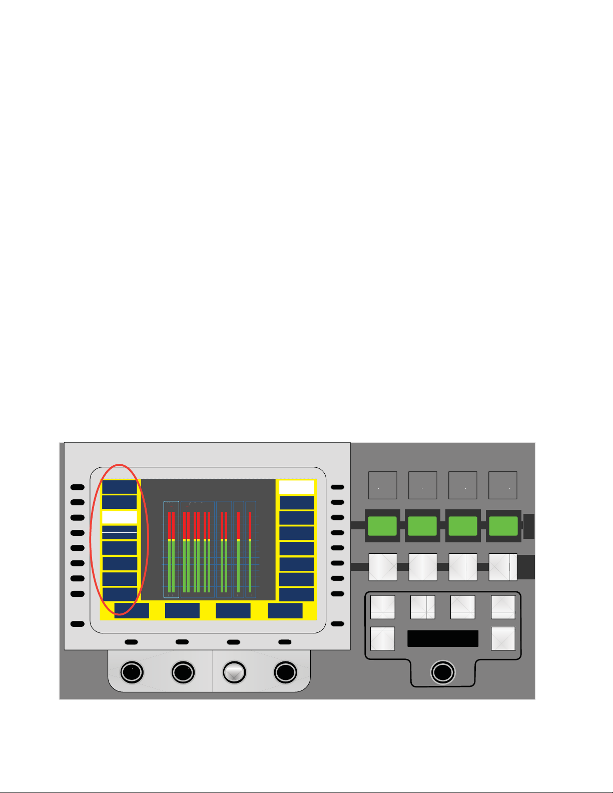
Audio Monitor Source Tally
Ø
Main
C
Lfe
LsR
1
Ø
Lt
Rt
Ø
D S
Sp
In the Audio Control panel screen, the “U” - shaped area around the left
and right edges and bottom of the screen in which the soft buttons appear
is called the “button area.” In many Audio Control screens, this button area
now has a background color that indicates whether or not the source currently active on the selected audio monitor point is contributing to Program
content, Preset content or neither.
• If the active monitor point source is contributing to Program content,
the button area background will be red as shown in Figure 7.
• If the active monitor point source is contributing to Preset content, the
button area background will be yellow as shown in Figure 8.
• If the active monitor point source is contributing to neither Program nor
Preset content, the button area background will be blue as shown in
Figure 9.
Figure 7. Monitor Point Contribution to Program
Audio Monitor Source Tally
AUDIO CONTROL
Options
ALM
Program
Preset
Aux
Clean Feed
Off-Air
Mix 1
Mix 2
Mix 3
Mix 4
Main D StrDolby 5.1
+3
+2
+1
0 VU
-1
-2
-3
-5
-7
-10
-20
LR
Aux / Main Stereo
< Source Name >
Dolby 5.
Ø
Ø
Lf RfCLfe Ls Rs Lt Rt M
Phase
Normal
Mix To
Main Stereo
Level
+
2.3 dB
Dolby 5.1
Surround
Dolby + 2
Spanish
French
Dolby-E
Group
Channel
Mapping
Home
Span Fren
an
Fren
tr
Ø
Balance
<
1.6 dB
M
s
Clean
Feed
ID
1
5.1 Lt-Rt Stereo
Mix To
Clean
Feed
ID
2
Mix To
Clean
Feed
Amin
2
Monitor
Reset
- 3 4 . 1
d B
Notice that the selected monitor point is the Aux bus. In the example in
Figure 7, the active source on the Aux bus is currently contributing to the
Program content (for example, as part of an on-air DVE effect). On the
Source Control panel, the button for that source on the Aux bus would also
be tallied with red illumination.
Mix To
Clean
Feed
EMRG
BCST
Mono
Dim
P
G
M
P
S
T
Maestro — Release Notes 19
Page 20

Version 1.500
Ø
Main
C
Lfe
LsR
1
Ø
Lt
Rt
Ø
D S
Sp
Figure 8. Monitor Point Contribution to Preset
AUDIO CONTROL
Options
ALM
Program
Preset
Aux
Clean Feed
Off-Air
Mix 1
Mix 2
Mix 3
Mix 4
Main D StrDolby 5.1
+3
+2
+1
0 VU
-1
-2
-3
-5
-7
-10
-20
LR
Aux / Main Stereo
< Source Name >
Dolby 5.
Ø
Ø
Lf RfCLfe Ls Rs Lt Rt M
Phase
Normal
Mix To
Main Stereo
Level
+
2.3 dB
Dolby 5.1
Surround
Dolby + 2
Spanish
French
Dolby-E
Group
Channel
Mapping
Home
Span Fren
an
Fren
tr
Ø
Balance
<
1.6 dB
M
s
Clean
Feed
ID
1
5.1 Lt-Rt Stereo
Mix To
Clean
Feed
ID
2
Mix To
Clean
Feed
Amin
2
Monitor
Reset
- 3 4 . 1
d B
Notice that the selected monitor point is the Aux bus. In the example in
Figure 8, the active source on the Aux bus is currently contributing to the
Preset content (for example, as part of a DVE effect preset to go on air with
the next transition). On the Source Control panel, the button for that source
on the Aux bus would also be tallied with yellow illumination.
Mix To
Clean
Feed
EMRG
BCST
Mono
Dim
P
G
M
P
S
T
20 Maestro — Release Notes
Page 21

Figure 9. Monitor Point Not Contributing to Program or Preset
Ø
Main
C
Lfe
LsR
1
Ø
Lt
Rt
Ø
D S
Sp
Audio Monitor Source Tally
AUDIO CONTROL
Options
ALM
Program
Preset
Aux
Clean Feed
Off-Air
Mix 1
Mix 2
Mix 3
Mix 4
Main D StrDolby 5.1
+3
+2
+1
0 VU
-1
-2
-3
-5
-7
-10
-20
LR
Aux / Main Stereo
< Source Name >
Dolby 5.
Ø
Ø
Lf RfCLfe Ls Rs Lt Rt M
Phase
Normal
Mix To
Main Stereo
Level
+
2.3 dB
Dolby 5.1
Surround
Dolby + 2
Spanish
French
Dolby-E
Group
Channel
Mapping
Home
Span Fren
an
Fren
tr
Ø
Balance
<
1.6 dB
M
s
Clean
Feed
ID
1
5.1 Lt-Rt Stereo
Mix To
Clean
Feed
ID
2
Mix To
Clean
Feed
Amin
2
Monitor
Reset
- 3 4 . 1
d B
Notice that the selected monitor point is the Aux bus. In the example in
Figure 9, the active source on the Aux bus is currently not contributing to
Program or Preset content. It may have been selected as part of a DVE
effect; however, DVE is not currently active. The source is, therefore, not
contributing to on-air Program content nor is it preset to go to air on the
next transition. On the Source Control panel, the button for that source on
the Aux bus would also be tallied with blue illumination.
Mix To
Clean
Feed
EMRG
BCST
Mono
Dim
P
G
M
P
S
T
Note In most cases, the tally color for a source on the PGM, PST or AUX bus will
match the button area background color on the Audio Control panel when
that bus is the active monitor point. However, under certain circumstances, it
is possible that the colors will not match. For example, if a DVE is selected
which has an Aux video enter mode and a Pgm audio mode, the PST bus tally
color will be blue for any source on that bus; however, if Preset is the active
monitor point in the Audio Control panel, the background button color will be
yellow. This occurs because the source selected on the PST bus will not be
contributing to Program content on the next transition (only AUX and PGM
are involved). The audio associated with the Aux source will be contributing
to the Program content on the next transition as it will become the active PGM
source on the next transition; therefore, Aux audio is currently Preset and the
button area background color is yellow.
Maestro — Release Notes 21
Page 22

Version 1.500
Audio/Video Breakaway
Before proceeding with the explanation of how to use the audio/video
breakaway capabilities introduced in Maestro software v1.5, it is important
to distinguish between audio/video breakaways and audio/video splits.
These definitions apply to the discussion which follows.
Breakaway: Selecting a combination of audio/video signals that are not
normally associated with each other and are assigned to different source
buttons. As an example, using one background button to select video from
“Server 1” and another background button to select audio from “Studio B.”
A breakaway can be performed on as many different buttons (sources) as
there are groups. For example, one background button may be used to
select video from “Server 1,” another button to select the “Main Stereo”
group from “Studio B,” and a third background button to select the “Dolby
5.1” group from '”Tape 2.”
The result of a breakaway is that multiple source buttons will be tallied to
indicate all sources which are contributing video or audio groups to the onair content.
Split: Selecting a combination of audio/video signals that are not normally
associated with each other and assigning those signals to the same background button. This allows the creation of a mixed source via the assignment of groups from multiple sources to a single button. Pressing the
button for that source would result in the routing of the multiple sources
assigned to that button. For example, one background button may be used
to select video from “Server 1” and audio from “Studio B.'”
Note Dynamic splits (i.e. user-created splits using control panel buttons) are NOT
supported in Maestro due to control panel limitations and the inability to
communicate all necessary information to the operator. Furthermore, given
the restrictions imposed on systems utilizing embedded audio, multiple
source splits would not be possible. Prior versions of Maesto software supported a V/A indicator on the PGM bus LCD button to indicate the presence
of a dynamic split using that source. This indicator is no longer needed and
should no longer appear on the PGM bus LCD buttons.
Static splits can be configured for non-embedded audio sources via the
Maestro Configuration Editor. A static split is a combination of video and
audio from different router sources. The mnemonic assigned to the LCD
button should represent the configured split and not just one of the
assigned sources.
22 Maestro — Release Notes
Page 23

Audio/Video Breakaway
An audio or video breakaway is performed with the Video and Audio
Source Control buttons located on the Source Control panel as shown in
Figure 10.
Figure 10. Video and Audio Source Control Buttons
E
Video Breakaway
In order to execute a video breakaway, the operator performs the following
steps:
1. Depress and hold the Video Source Control button. While the button is
depressed, it will remain illuminated.
Note On the GUI control panel, the Video Source Control button will toggle on and
off with each touch since it cannot be held down.
2. Select the desired video source on the desired background bus (PGM,
PST or AUX). The selected video source will tally high (brighter
illumination) while the source(s) from which the audio is derived tallies
low (dimmer illumination).
3. Release the Video Source Control button. Button illumination will
extinguish and the breakaway will be active.
If a breakaway is active on the PGM, PST or AUX bus, selecting a different
source on the same bus (without the Video our Audio Source Control
button depressed) will result in the de-selection of all breakaways on that
bus and the selection of the “as configured” desired source. If a breakaway
is desired with the new source, the steps above must be repeated.
Maestro — Release Notes 23
Page 24

Version 1.500
Audio Breakaway
It is possible to create audio breakaways by selecting one or more audio
groups from one or more background bus source buttons. These breakaways can include the following:
• All audio groups from a single source
• One or more audio groups from multiple sources
Before initiating a breakaway, the audio monitor point must be set to Program, Preset or Aux. If one of these is not the active monitor point, the error
screen in Figure 11 appears.
Figure 11. Audio Breakaway Error - Incorrect Monitor Point
AUDIO CONTROL
Options
ALM
Program
Preset
Aux
Clean Feed
Off-Air
Mix 1
Mix 2
Mix 3
Mix 4
Multi-Source Audio Breakaway
Please select Program, Preset
or Aux Monitor Point
+2
+1
0 VU
-1
-2
-3
-5
-7
-10
-20
LR LfRfCLfe Ls Rs Lt Rt M
Mix To
Clean
Feed
ID
1
Mix To
Clean
Feed
ID
2
Mix To
Clean
Feed
Amin
2
Mix To
Clean
Feed
EMRG
BCST
P
G
M
P
S
T
M
Home
5.1 Lt-Rt Stereo
Monitor
Reset
- 3 4 . 1
d B
Mono
Dim
24 Maestro — Release Notes
Page 25

Audio/Video Breakaway
Audio Breakaway - All Audio Groups From a Single Source
In order to execute an audio breakaway of all audio groups from a single
background bus source, the operator performs the following steps:
1. Depress and hold the Audio Source Control button. While the button is
depressed, it will remain illuminated. The Audio Source Control button
must remain depressed throughout the breakaway operation.
Note On the GUI control panel, the Audio Source Control button will toggle on and
off with each touch since it cannot be held down.
If the error screen in Figure 11 appears, release the Audio Source
Control button, select a valid monitor point (Program, Preset or Aux) in
the Audio Control Home screen and depress and hold the Audio
Source Control Button again.
Note Releasing the Audio Source Control button at any time during the Audio
Breakaway process will result in all operations to that point in the process
being cancelled and the Audio Source Control button illumination will be
extinguished.
With the Audio Source Control button depressed, the Audio Control
panel screen will display either Figure 12 Audio Breakaway Status Screen
or Figure 13 Multi-Source Audio Breakaway - Source Selection Screen. The
screen that is initially displayed will be the one last used in the most
recent audio breakaway operation.
2. To breakaway all audio groups for a particular background bus (PGM,
PST, AUX), press the desired source button on the appropriate bus. The
source from which the audio is broken away will tally low (dim
illumination). To perform a breakaway of selected groups from one or
more sources, proceed to Audio Breakaway - One Or More Audio Groups
From Multiple Sources.
3. Release the Audio Source Control button. The Audio Source Control
button illumination will extinguish and the breakaway will be active.
If a breakaway is active on the PGM, PST or AUX bus, selecting a different
source on the same bus (without the Video our Audio Source Control
button depressed) will result in the de-selection of all breakaways on that
bus and the selection of the “as configured” desired source. If a breakaway
is desired with the new source, the steps above must be repeated.
Maestro — Release Notes 25
Page 26

Version 1.500
Audio Breakaway - One Or More Audio Groups From Multiple Sources
Before performing a breakaway, it is important to understand the functions
of the Audio Breakaway Status Screen in Figure 12.
Figure 12. Audio Breakaway Status Screen
AUDIO CONTROL
Options
ALM
Main Stereo
<Source>
Dolby 5.1
<Source>
Dolby + 2
<Source>
Spanish
<Source>
French
<Source>
Scroll
Input
Audio Breakaway Status
<Bus>
Multi-Source
Breakaway
Main Stereo
<Status>
Dolby 5.1
<Status>
Dolby + 2
<Status>
Spanish
<Status>
French
<Status>
Scroll
Output
Home
Mix To
Clean
Feed
ID
1
5.1 Lt-Rt Stereo
Reset
Mix To
Clean
Feed
ID
2
Monitor
- 3 4 . 1
Mix To
Clean
Feed
Amin
2
d B
Mix To
Clean
Feed
EMRG
BCST
Mono
Dim
The Audio Breakaway Status Screen provides the following information and
controls:
Audio Input Group Name and <Source> - Appears on the left side of the screen.
•
The audio input group name is the first line of text and the mnemonic
for the selected source for that group appears on the second line. Since
Maestro has no way of representing this information on the LCD
buttons of the background busses, it is from this status screen that the
audio groups to be broken away and sources are identified
P
G
M
P
S
T
Audio Output Group Name and <Status> - Appears on the right side of the
•
screen. Audio output group names come from the Audio Output Set
defined in the Maestro Configuration Editor. The first line of text is the
audio group name. The second line of text is the group status. The
<Status> line will be blank unless the named audio group is not defined
for the selected source. In this case, the <Status> line will display
“Muted-no map.”
Note Any audio output group(s) that is not defined for that source, either explicitly
or via channel mapping, will be muted upon selection. It will display as
“Muted-no map” in the Audio Output Group status line.
26 Maestro — Release Notes
Page 27

Audio/Video Breakaway
• Scroll Input - The first knob (from the left) is used to scroll the audio input
group names vertically when more than eight group names have been
defined. One “click” of the knob will scroll the name up or down
depending upon the direction. Turning the knob to the right scrolls the
list up. Turning the knob to the left scrolls the list down. Pressing the
button above the knob resets the list to the default position in which the
first audio group is aligned with the top left button.
Active Background Bus - The second knob (from the left) is used to change
•
the active background bus for breakaways. The default label is the bus
currently active as the Audio Monitor point on Audio Control panel
Home screen (Program, Preset or Aux). The active bus can be changed
by turning the knob. Changing the bus will result in the input group
names and associated source mnemonics being updated to reflect those
associated with the selected bus. The channel mapping displayed in the
Audio Breakaway screen will reflect the channel mapping associated
with the selected bus. Pressing the button above the knob will result in
resetting the bus to the default Audio Monitor point.
•
Multi-Source Breakaway - The third knob (from the left) is labelled Multi-
Source Breakaway. The knob itself has no function; however, the button
above the knob is used to toggle between the Audio Breakaway Status
screen and the Multi-Source Breakaway screen where breakaways can
be created.
Scroll Output - The fourth knob (from the left) is used to scroll the audio
•
output group names vertically when more than eight group names
have been defined. One “click”of the knob will scroll the name up or
down depending upon the direction. Turning the knob to the right
scrolls the list up. Turning the knob to the left scrolls the list down.
Pressing the button above the knob resets the list to the default position
in which the first audio group is aligned with the top right button.
When the appropriate selections have been made in the Audio Break-
away Status Screen, press the button above the third knob to display the
Multi-Source Audio Breakaway - Source Selection Screen.
In order to execute an audio breakaway of one or more audio groups from
multiple background bus sources, the operator performs the following
steps:
1. Depress and hold the Audio Source Control button. While the button is
depressed, it will remain illuminated. The Audio Source Control button
must remain depressed throughout the breakaway operation.
Releasing the Audio Source Control button at any time during the
Audio Breakaway process will result in all operations to that point in
the process being cancelled and the Audio Source Control button
illumination will be extinguished.
Maestro — Release Notes 27
Page 28

Version 1.500
Note On the GUI control panel, the Audio Source Control button will toggle on and
off with each touch since it cannot be held down.
2. Select the Multi-Source Audio Breakaway - Source Selection Screen (if it is
not the active screen) by pressing the
Multi-Source Breakaway button
associated with the third (from the left) knob under the audio control
screen. This button acts as a toggle between the Audio Breakaway
Status screen and the Multi-Source Audio Breakaway screen.
Figure 13. Multi-Source Audio Breakaway - Source Selection Screen
AUDIO CONTROL
Options
ALM
1
VTR1
2
VTR2
3
VTR3
4
Server 1
5
Server 2
6
Server 3
7
Sat 1
8
Sat 2
Multi-Source Audio Breakaway
1) Select Breakaway Source
+2
2) Select Breakaway Group(s)
+1
0 VU
-1
-2
3) Confirm Breakaway by selecting
-3
same Source on desired
-5
-7
Background Bus
-10
-20
LR LfRfCLfe Ls Rs Lt Rt M
Breakaway
M
Status
3. The Multi-Source Audio Breakaway - Source Selection Screen displays the
steps for performing a breakaway. The first step is to select the
breakaway source. The 16 soft buttons (eight on the left side and eight
on the right side) are labeled with the source names assigned to the 16
background bus LCD buttons. The first line of text is a number
corresponding to the background LCD button number (from 1 to 16 left
to right on the PGM bus). The second line of text is the mnemonic/
name of the source assigned to that button.
9
Sat 3
10
EMRG BCST
11
Bars
12
Apology
13
ID1
14
15
16
Net East
Home
Mix To
Clean
Feed
ID
1
5.1 Lt-Rt Stereo
Reset
Mix To
Clean
Feed
ID
2
Monitor
- 3 4 . 1
Mix To
Clean
Feed
Amin
2
d B
Mix To
Clean
Feed
EMRG
BCST
Mono
Dim
P
G
M
P
S
T
Select the source from which audio group(s) should be broken away by
pressing the small black button next to the desired source label. Once
the source is selected, its button number and name appear in light blue
text under Step 1) Select Breakaway Source. The second step, 2) Select
Breakaway Group(s), will now be highlighted in yellow text.
28 Maestro — Release Notes
Page 29

Figure 14. Multi-Source Audio Breakaway - Group Selection Screen
Audio/Video Breakaway
AUDIO CONTROL
Options
ALM
Main Stereo
Dolby 5.1
Dolby + 2
Spanish
French
Multi-Source Audio Breakaway
1) Select Breakaway Source:
Button 5 - Server 2
+2
2) Select Breakaway Group(s)
+1
0 VU
-1
-2
3) Confirm Breakaway by selecting
-3
same Source on desired
-5
-7
Background Bus
-10
-20
L R Lf RfCLfe Ls Rs Lt Rt M
Breakaway
M
Status
4. The 16 soft buttons (eight on the left side and eight on the right side) are
labeled with the Audio Input Set audio group names associated with
the source selected in Step 3 above.
Home
Mix To
Clean
Feed
ID
1
5.1 Lt-Rt Stereo
Reset
Mix To
Clean
Feed
ID
2
Monitor
- 3 4 . 1
Mix To
Clean
Feed
Amin
2
d B
Mix To
Clean
Feed
EMRG
BCST
Mono
Dim
P
G
M
P
S
T
Select the desired group(s) to be broken away by pressing the black
button next to the desired group name(s). The group name label soft
button for each selected group is highlighted. Pressing the black button
next to an already selected group deselects that group. As one or more
groups are selected, the screen will be similar to the one shown in
Figure 15.
Note In the example in Figure 15, the Main Stereo, Dolby 5.1 and Dolby + 2 groups
from the Server 2 source will be broken away and will be switched. The
Spanish and French groups will not be switched.
Maestro — Release Notes 29
Page 30

Version 1.500
Figure 15. Multi-Source Audio Breakaway - Confirm Breakaway Screen
AUDIO CONTROL
Options
ALM
Main Stereo
Dolby 5.1
Dolby + 2
Spanish
French
Multi-Source Audio Breakaway
1) Select Breakaway Source:
Button 5 - Server 2
+2
2) Select Breakaway Group(s)
+1
0 VU
-1
-2
3) Confirm Breakaway by selecting
-3
same Source on desired
-5
-7
Background Bus
-10
-20
LR LfRfCLfe Ls Rs Lt Rt M
Breakaway
M
Status
5. To confirm (execute) the breakaway, press the background bus button
(on the PGM, PST or AUX bus) that corresponds to the source that
appears highlighted beneath Step 1 in the Multi-Source Audio Breakaway
- Confirm Breakaway Screen.
Home
Mix To
Clean
Feed
ID
1
5.1 Lt-Rt Stereo
Reset
Mix To
Clean
Feed
ID
2
Monitor
- 3 4 . 1
Mix To
Clean
Feed
Amin
2
d B
Mix To
Clean
Feed
EMRG
BCST
Mono
Dim
P
G
M
P
S
T
If any source button on the background busses is pressed other than the
source highlighted beneath Step 1 in the Multi-Source Audio Breakaway -
Confirm Breakaway Screen, the breakaway will not be executed and the
Multi-Source Audio Breakaway - Confirm Breakaway Error Screen in
Figure 16 will appear with Step 3 highlighted in red to indicate the error
condition.
To correct the error condition, select the correct source as indicated
under step 1 in the screen.
30 Maestro — Release Notes
Page 31

Audio/Video Breakaway
Figure 16. Multi-Source Audio Breakaway - Confirm Breakaway Error Screen
AUDIO CONTROL
Options
ALM
Main Stereo
Dolby 5.1
Dolby + 2
Spanish
French
Multi-Source Audio Breakaway
1) Select Breakaway Source:
Button 5 - Server 2
+2
2) Select Breakaway Group(s)
+1
0 VU
-1
-2
3) Confirm Breakaway by selecting
-3
same Source on desired
-5
-7
Background Bus
-10
-20
L R Lf RfCLfe Ls Rs Lt Rt M
Breakaway
M
Status
6. Release the Audio Source Control button. The Audio Source Control
button illumination will be extinguished and the Audio Control panel
display will return to the previously active audio control screen.
Home
Mix To
Clean
Feed
ID
1
5.1 Lt-Rt Stereo
Reset
Mix To
Clean
Feed
ID
2
Monitor
- 3 4 . 1
Mix To
Amin
Clean
Feed
2
d B
Mix To
Clean
Feed
EMRG
BCST
Mono
Dim
P
G
M
P
S
T
Note If a breakaway is active on the PGM, PST or AUX bus, selecting a different
source on the same bus (without the Video or Audio Source Control button
depressed) will result in the de-selection of all breakaways on that bus and
the selection of the “as configured” desired source. If a breakaway is desired
with the new source, the steps above must be repeated.
Maestro — Release Notes 31
Page 32

Version 1.500
Ø
Main
C
Lfe
LsR
1
Ø
Lt
Rt
Ø
D S
Sp
Dynamic Channel Mapping
Dynamic channel mapping is the operator-controlled process of mapping
audio input groups into audio output groups from the control panel (hardware control panel or GUI).
Static channel maps configured via the Audio Input Set tables in the
Maestro Configuration Editor are the default channel maps for their associated sources.
If a predefined mapping between audio input groups and audio output
groups does not exist, or, the operator wishes to alter existing static channel
mappings, dynamic channel mapping makes that possible.
The Channel Mapping screen is accessed by pressing the small black button
to the right of the
screen as seen in Figure 17.
Figure 17. Audio Control Home Screen - Channel Mapping
Channel Mapping soft button on the Audio Control Home
AUDIO CONTROL
Options
ALM
Program
Preset
Aux
Clean Feed
Off-Air
Mix 1
Mix 2
Mix 3
Mix 4
Main D StrDolby 5.1
+3
+2
+1
0 VU
-1
-2
-3
-5
-7
-10
-20
LR
Aux / Main Stereo
< Source Name >
Dolby 5.
Ø
Ø
Lf RfCLfe Ls Rs Lt Rt M
Phase
Normal
Mix To
Main Stereo
Level
+
2.3 dB
Dolby 5.1
Surround
Dolby + 2
Spanish
French
Dolby-E
Group
Channel
Mapping
Home
Span Fren
an
Fren
tr
Ø
Balance
<
1.6 dB
M
s
Clean
Feed
ID
1
5.1 Lt-Rt Stereo
Mix To
Clean
Feed
ID
2
Mix To
Clean
Feed
Amin
Monitor
Reset
- 3 4 . 1
When the Channel Mapping button is pressed, a screen similar to the one
shown in Figure 18 appears.
2
d B
Mix To
Clean
Feed
EMRG
BCST
Mono
Dim
P
G
M
P
S
T
32 Maestro — Release Notes
Page 33

Figure 18. Channel Mapping Screen
Dynamic Channel Mapping
AUDIO CONTROL
Options
ALM
Main Stereo
<Source>
Dolby 5.1
<Source>
Dolby + 2
<Source>
Spanish
<Source>
French
<Source>
Scroll
Input
< Monitor Point > / < Source Name >
Default
Mapping
Un-Map
Main Stereo
<Status>
Dolby 5.1
<Status>
Dolby + 2
<Status>
Spanish
<Status>
French
<Status>
Scroll
Output
Home
Mix To
Clean
Feed
ID
1
5.1 Lt-Rt Stereo
Reset
Mix To
Clean
Feed
ID
2
Monitor
- 3 4 . 1
Mix To
Clean
Feed
Amin
2
d B
The Channel Mapping Screen provides the following information and controls:
<Monitor Point> - Indicates the audio source (Program, Preset, Aux, Clean
•
Feed, etc.) being monitored on the Audio Control Home Screen.
Mix To
Clean
Feed
EMRG
BCST
Mono
Dim
P
G
M
P
S
T
Note The background color behind the soft buttons indicates the status of the
audio being monitored. If it is red, it is on-air and contributing to Program
content. If it is yellow, it will go to air on the next transition and is contributing
to Preset content. If it is blue, it is not currently on-air nor will it be going to
air on the next transition. For more information, see Audio Monitor Source
Tally on page 19.
• <Source Name> - Indicates the name/mnemonic of the source whose
input group is currently mapped to the monitored output group.
Audio Input Group Name and <Source> - Appears on the left side of the screen.
•
The audio input group name is the first line of text and the mnemonic
for the selected source for that group appears on the second line.
Audio Output Group Name - Appears on the right side of the screen. Audio
•
output group names come from the Audio Output Set defined in the
Maestro Configuration Editor. The first line of text is the audio group
name. The second line of text is the group status. The <Status> line will
be blank unless the named audio group is not defined for the selected
source.
Maestro — Release Notes 33
Page 34

Version 1.500
Note Any audio output group(s) that is not defined for that source, either explicitly
or via channel mapping, will be muted upon selection. It will display as
“Muted-no map” in the Audio Output Group status line.
• Scroll Input - The first knob (from the left) is used to scroll the audio input
group names vertically when more than eight group names have been
defined. One “click” of the knob will scroll the name up or down
depending upon the direction. Turning the knob to the right scrolls the
list up. Turning the knob to the left scrolls the list down. Pressing the
button above the knob resets the list to the default position in which the
first audio group is aligned with the top left button.
Default Mapping - Pressing this button will reset the channel mapping to
•
the Audio Input Set defined in the selected configuration for the
selected video source. The knob (second from the left) has no function.
Un-Map - Pressing this button will allow audio output groups to be un-
•
mapped from their associated input groups. The knob (third from the
left) has no function. See Un-Mapping Channels on page 38 for details.
Scroll Output - The fourth knob (from the left) is used to scroll the audio
•
output group names vertically when more than eight group names
have been defined. One “click”of the knob will scroll the name up or
down depending upon the direction. Turning the knob to the right
scrolls the list up. Turning the knob to the left scrolls the list down.
Pressing the button above the knob resets the list to the default position
in which the first audio group is aligned with the top right button.
34 Maestro — Release Notes
Page 35

Channel Mapping Process
Audio channel mapping is performed by executing the following steps:
1. On the Channel Mapping Screen, select an audio input group by
pressing the small black button to the left of the desired group name.
Selecting a group causes the group name and source label to be
highlighted in a light blue color.
Note On the GUI, the soft buttons (group name labels) are used to make selections
on the Audio Control panel. On the hardware Audio Control panel, the LCD
screen is not a touch screen and only the small black hard button is used to
make a selection.
Audio input group selection is mutually exclusive. Only one group at a
time may be selected. Selecting a different group will cause the previously selected group to be deselected and the highlight color will extinguish. Pressing the small black button for an already selected group
will also cause that group to be deselected.
2. Select an audio output group by pressing the small black button to the
right of the desired group name. Selecting the output group causes the
following to occur:
Dynamic Channel Mapping
a. The selected audio input group will be mapped to the selected
audio output group. This is indicated by a line and arrow from the
input group to the output group.
b. The selected audio output group will be highlighted and the audio
monitor will be switched to that group.
c. The selected audio input group will be deselected and the highlight
color will be extinguished.
If no audio input group is selected before selecting the audio output
group, no mapping occurs but the audio monitor switches to the
selected audio output group.
Note Channel remapping is a one-to-n relationship. Each audio input group can be
mapped to one or more audio output groups; however, each audio output
group can be associated with only one audio input group.
3. Repeat Step 1 and Step 2 above until all desired audio channel maps are
complete.
Note Dynamic channel mappings performed while breakaways are active are tem-
porary. These channel maps are not stored and recalled with Source Memory.
Dynamic channel mapping performed while breakaways are not active (i.e.
audio from a single source) will be automatically stored and recalled as part
of Source Memory.
To return to the Home screen on the Audio Control display, press the Home
button.
Maestro — Release Notes 35
Page 36

Version 1.500
Audio Output Group Substitution
Typically, there is a one-to-one correspondence between audio input
groups and audio output groups as seen in Figure 18 on page 33. However,
it is possible in some cases that an audio input group does not exist for all
audio output groups. In this case, it may be desirable to map one input
group to several output groups so that an audio signal exists on all output
groups. Figure 19 shows an example of this where the “Main Stereo” audio
input group is mapped to the “Spanish” and “French” Mono output groups
since there are no Spanish and French audio input groups in the source.
Figure 19. Audio Output Group Substitution
AUDIO CONTROL
Options
ALM
Main Stereo
<Source>
Dolby 5.1
<Source>
Dolby + 2
<Source>
Scroll
Input
< Monitor Point > / < Source Name >
Default
Mapping
Un-Map
This scenario requires a down mix of the stereo input group to the mono
output groups. Given the available audio groups in Maestro (mono, stereo,
Dolby 5.1, Dolby 7.1 and Dolby E Pass Through), there is a known set of
possible channel mappings and down-mix, up-mix definitions. These mappings are built into Maestro and require no configuration.
Main Stereo
<Status>
Dolby 5.1
<Status>
Dolby + 2
<Status>
Spanish
<Status>
French
<Status>
Scroll
Output
Home
Mix To
Clean
Feed
ID
1
5.1 Lt-Rt Stereo
Reset
Mix To
Clean
Feed
ID
2
Monitor
- 3 4 . 1
Mix To
Clean
Feed
Amin
2
d B
Mix To
Clean
Feed
EMRG
BCST
Mono
Dim
P
G
M
P
S
T
36 Maestro — Release Notes
Page 37

Dynamic Channel Mapping
Another typical scenario might involve the mapping of a single stereo
input group to all output groups which may be mono, stereo or multichannel surround. Figure 20 is an example of this type of mapping.
Figure 20. Stereo Audio Mixer Source Remapping
AUDIO CONTROL
Options
ALM
Main Stereo
<Source>
Scroll
Input
< Monitor Point > / < Source Name >
Default
Mapping
Un-Map
Main Stereo
<Status>
Dolby 5.1
<Status>
Dolby + 2
<Status>
Spanish
<Status>
French
<Status>
Scroll
Output
Home
Mix To
Clean
Feed
ID
1
5.1 Lt-Rt Stereo
Reset
Mix To
Clean
Feed
ID
2
Monitor
- 3 4 . 1
Mix To
Clean
Feed
Amin
2
d B
In this scenario, both a down mix to mono and an up mix to multi-channel
surround groups would be required. These mappings are built into
Maestro and require no configuration.
Mix To
Clean
Feed
EMRG
BCST
Mono
Dim
P
G
M
P
S
T
Maestro — Release Notes 37
Page 38

Version 1.500
Un-Mapping Channels
If a mapping exists between an audio input group and one or more audio
output groups and that mapping is no longer desirable or necessary, it is
possible to undo those mappings.
To un-map one or more audio output groups from an audio input group the
operator performs the following steps:
1. On the Channel Mapping Screen, press the small black button under
Un-Map label.
the
Un-Map button highlight color changes to red indicating that the Un-
The
Map process has been initiated.
2. Select the audio output group (right side of display) which you wish to
un-map from its associated audio input group by pressing the small
black button next to the group name label.
The mapping, as indicated by the arrow from the input group to the
output group is deleted. See Figure 21.
Options
ALM
Main Stereo
<Source>
Dolby 5.1
<Source>
Dolby + 2
<Source>
Scroll
Input
3. Repeat Step 1 and Step 2 for all groups you wish to Un-Map.
Figure 21. Un-Mapping Channels
< Monitor Point > / < Source Name >
Default
Mapping
Un-Map
Main Stereo
<Status>
Dolby 5.1
<Status>
Dolby + 2
<Status>
Spanish
<Status>
French
<Status>
Scroll
Output
Home
Mix To
Clean
Feed
ID
1
5.1 Lt-Rt Stereo
Reset
Mix To
Clean
Feed
ID
2
Monitor
- 3 4 . 1
AUDIO CONTROL
Mix To
Clean
Feed
Amin
2
d B
Mix To
Clean
Feed
EMRG
BCST
Mono
Dim
P
G
M
P
S
T
In this example, the Spanish and French output groups (shown in Figure 19
mapped to the Main Stereo input group) have been un-mapped.
38 Maestro — Release Notes
Page 39

Battery Charging Status
The Maestro Deployment Control Center now displays the battery
charging status of each Maestro component in the Network Description
table. See Figure 22.
Figure 22. Maestro Deployment Control Center Battery Charging Status Display
Battery Charging Status
Placing the cursor over the battery status icon for a Maestro component displays hover text which indicates the battery status and battery charger
status for that particular component.
The battery status icons and their descriptions appear in Table 3 .
Table 3. Battery Charging Status Icons and Descriptions
Icon Description Icon Description Icon Description
Battery: Charged
Charger: Enabled
Battery: Charging
Charger: Enabled
Battery: Discharged
Charger: Enabled
Battery: Not Present
Battery: Present
Charger: Unknown
Battery: Charged
Charger: Disabled
Battery: Discharged
Charger: Disabled
Battery: Not Present
Battery: Not Present
Charger: Unknown
Battery: Unknown
Charger: Enabled
Battery: Unknown
Charger: Disabled
Charger: Enabled
Charger: Disabled
Maestro — Release Notes 39
Page 40

Version 1.500
Software Upgrade Procedure
CAUTION Portions of this procedure will interrupt video and audio signals passing
through the system. Users of this equipment should consult with Grass
Valley Technical Support personnel before proceeding.
Maestro Deployment PC
Note In some installations, the “deployment PC” will be the same as the GUI PC.
Requirements
• A period of time where the Maestro system can be taken off-line (externally bypassed).
• Windows XP Service Pack 2.
• In order to upgrade the Maestro software, the Maestro configuration
computer will need access to the installation CD or downloaded installation files.
• The configuration from the existing operational Maestro system will be
used to complete the Maestro upgrade.
40 Maestro — Release Notes
Page 41

Installing the Maestro Software Package
Note It is recommended that all default values be used during the installation.
1. Make a copy of the current configuration set:
a. Launch the Maestro Configuration Editor by going to “Start > All
Programs > Thomson > Maestro Configuration Editor.”
b. Use “File > Open” to open the current configuration set.
c. Use “File > Save As” to create a copy of the set.
As a suggestion, add “v14” to the name.
d. Use “File > Save As” again to create another copy of the set.
As a suggestion, add “v15” to the name.
e. Close all Maestro applications.
2. The previous version of Maestro software must be uninstalled before a
new version can be installed. The software can be manually removed
by following the steps below. It can also be automatically removed by
initiating the new software installation procedure in Step 3.
Software Upgrade Procedure
CAUTION If you are uninstalling v1.3 or v1.4 software, you must use the Administrator
account (login). If you are uninstalling v1.2 or prior software, you must use
the account (login) used when that software was installed.
a. Using the Windows Control Panel, select Add or Remove
Programs.
b. Remove the Maestro Software Package.
This will not remove user data.
c. Close the Windows Control Panel.
3. Insert the new Maestro software CD.
As shown in Figure 23, when the installation auto runs from the CD, or
is started manually, previously installed Maestro software is automatically detected. The operator is prompted to confirm uninstallation of
this software before proceeding with the installation of the new software.
Maestro — Release Notes 41
Page 42

Version 1.500
Figure 23. Automatic Detection of Prior Software Version
a. Click the Next button to proceed with removal of the previous
software version.
A popup will appear that asks if the install should continue. Click on
Next. Go to Step 4.
If the installation does not automatically start, the process will have to
be started manually:
b. Select Start > Run.
A window similar to that shown in Figure 24 should appear.
Figure 24. Run Dialog Box
c. Enter “E:\MaestroInstall.exe” where E: is the CD Drive.
d. Click the OK button.
42 Maestro — Release Notes
Page 43

Software Upgrade Procedure
Note If you enter “Setup.exe” in the Run dialog box instead of ‘MaestroInstall.exe,”
the window in Figure 25 appears and the prior Maestro software version
must be manually removed through Add/Remove Programs in the Windows
Control Panel. If this window appears, click the OK button and return to
Step 2 on page 41.
Figure 25. Setup.exe Add/Remove Programs Prompt
A popup will appear that asks if the install should continue; select Next.
Go to Step 4.
4. A popup will indicate the default destination folder. Select Next.
5. For Setup Type, select Complete.
6. When the “Ready to Install” menu appears, select Install.
The window shown in Figure 26 will appear.
Figure 26. Installing Maestro Software Package
When the software installation is complete, the window shown in Figure 27
will appear.
Maestro — Release Notes 43
Page 44

Version 1.500
Figure 27. Maestro Software Package Installation Complete
7. Select Finish.
Installation of the Maestro Software Package on the PC is now complete.
Note If the installation fails to complete and you see the error message “Error 1001
-- the specified service already exists,” you may need to manually remove the
Maestro Jupiter Router Service software. Refer to Manually Removing the
Maestro Jupiter Router Service Software on page 45.
44 Maestro — Release Notes
Page 45

Software Upgrade Procedure
Manually Removing the Maestro Jupiter Router Service Software
Perform this procedure only if you see the error message “Error 1001 -- the
specified service already exists” referred to in the Note on page 44.
1. Go to “Control Panel > Administrative Tools > Services.”
2. Right click on “MaestroJupiterRouterService” and select Stop.
3. Go to “Start > Run” and enter “regedit.”
4. Go to “HKEY_LOCAL_MACHINE > SYSTEM > CurrentControlSet >
Services.”
5. Highlight “MaestroJupiterRouterService.” Right click and delete this
item.
6. Close all windows and reboot. Repeat Step 1 above and confirm that
MaestroJupiterRouterService is not listed.
7. Proceed with re-installation of the new software, starting with Step 3 on
page 41.
Maestro — Release Notes 45
Page 46

Version 1.500
Re-compiling the Configuration File
It is highly recommended that all configuration sets to be used with
Maestro software version 1.5 be recompiled with the v1.5 Configuration
Editor. This will add Bkgd D as an available input for embedded audio
breakaways.
Recompiling is required if performing a software update when the prior
software was v1.3 or older. Changes have been made to the structure of the
Monitor Follow configuration table.
1. Launch the Maestro Configuration Editor by going to “Start > All
Programs > Thomson > Maestro Configuration Editor.”
2. Select the Maestro configuration set to be re-compiled by going to “File
> Open > Thomson” and selecting the set.
This should be the configuration set created for v1.500 use (Step d on
page 41).
3. If the system displays a Validation Report, you must check the
indicated table(s) and make corrections as indicated.
You can use the links in the Description column to display the table(s).
4. Save the configuration file.
5. Compile the file by going to “File > Compile Channel Data.”
6. Proceed to Updating the System Configuration and Software below.
46 Maestro — Release Notes
Page 47

Updating the System Configuration and Software
1. Launch the Maestro Deployment control center by selecting “Start > All
Programs > Thomson > Maestro Deployment Center.
A Maestro Deployment Control Center window similar to that shown
in Figure 28 appears.
Figure 28. Maestro Deployment Control Center (example)
Software Upgrade Procedure
2. (Optional) Select Show Log to provide detailed monitoring of the update
process.
3. In the Configuration box:
a. Verify that the Folder field has the correct path to the Maestro
configuration directory. (Default = C:\Thomson)
b. In the “File:” drop down field, select the Maestro configuration set
to be activated.
This should be the configuration set updated and compiled for v1.500
use (Step 5 on page 46).
Maestro — Release Notes 47
Page 48

Version 1.500
c. The Configuration box contains two buttons: Update Only and Update
and Apply
•
•
.
Update Only - Downloads the selected configuration file to the
boards, but, does not apply it as the running configuration. The
selected configuration files appears in the “Pending>>” row.
The currently active configuration appears in the “Running>>”
rows.
Update & Apply - Downloads the selected configuration file to the
boards and applies it as the running configuration.
Click on the
This will update the contents of the “Pending>>” and “Running>>”
rows in the Board Configuration and Active Configuration columns
and make the selected configuration the active configuration.
Note If the Update Only button is clicked, the configuration file does not become
the active configuration until the Apply Pending button is clicked to activate
the “pending” configuration.
CAUTION The following step will interrupt the video and audio signals passing through
the system for about 1 minute.
4. In the Software Application box:
a. The “Folder” field should indicate “C:\MaestroEmbedded.”
b. In the Frame Processor Tar File Name field:
--For LTC systems (those using Linear Time Code) select
“MaestroMC_1.500.2841.950.LTC.tar.” (When used, LTC is connected to pins 43 and 44 of the GPIO connector on the rear panel.)
--For VITC systems (those using Vertical Interval Time Code) select
“MaestroMC_1.500.2841.950.VITC.tar.”
Update & Apply button.
c. In the Control Panel Tar File Name, field, select
“MaestroCP_1.500.2841.950.tar.”
5. Click the Select All button (lower right corner of menu).
Alternatively, each board can be updated independently by clicking on
the "Board Name" field or all at the same time by using the "Select All"
button.
48 Maestro — Release Notes
Page 49

Software Upgrade Procedure
6. The Software Application box contains two buttons: Update Only and
Update and Apply.
Update Only - Downloads the selected configuration file to the
•
boards, but, does not apply it as the running configuration. The
selected configuration files appears in the “Pending>>” row.
The currently active configuration appears in the “Running>>”
rows.
Update & Apply - Downloads the selected configuration file to the
•
boards and applies it as the running configuration.
CAUTION The following step will interrupt the video and audio signals passing through
the system for about 1 minute.
Click on the Update & Apply button.
This will update the contents of the “Pending>>” and “Running>>”
rows in the Board Configuration and Active Configuration columns
and make the selected configuration the active configuration.
This will update the contents of the “Running>>” rows in the Version
columns.
Note If the Update Only button is clicked, the configuration file does not become
the active configuration until the Apply Pending button is clicked to activate
the “pending” configuration.
7. Verify that the new Configuration and Application versions are
“Running” as seen in Figure 29.
8. Proceed to Checking the Boot ROM Versions on page 51.
Maestro — Release Notes 49
Page 50

Version 1.500
Figure 29. Maestro Deployment Control Center Software Version Status
50 Maestro — Release Notes
Page 51

Checking the Boot ROM Versions
Maestro software version 1.4 and above require the Processor and hardware control panel boot ROMs to be current. (Older versions of the boot
ROMs will operate under v1.4 and above but this would require the
deployment PC and system software to be active at all times.)
Note The procedure documented in this section can only be done after upgrading
to v1.5 of the Maestro Software Package and updating the software following
the instructions in the prior section. Previous software versions do not
support checking the Boot ROM version in the manner described below. If
you have not upgraded to the v1.5 software, you must use the Telnet procedure documented in the v1.4 Release Notes.
1. In the Maestro Deployment Control Center window, select the
Processor for which you wish to check the Boot ROM version. The row
for the selected Processor will have a dark background.
2. Right-click on the FPGA version number in the “Running>>” row of
the selected Processor. A window similar to the one seen in Figure 30
appears.
Software Upgrade Procedure
Figure 30. Processor Board Boot ROM and FPGA/CPLD Update Window
3. Verify that the date that appears in the “Loaded” column for the
BOOTROM is Dec 14 2006.
• If, as in the example in Figure 30, you see an older date, or no date
at all, the Boot ROM should be updated. Contact Grass Valley Technical Support for update instructions.
Maestro — Release Notes 51
Page 52

Version 1.500
4. If there is another Processor (channel) in the system, repeat Step 1
above and following steps. If not, go to Step 5.
5. In the Maestro Deployment Control Center window, select the control
panel for which you wish to check the Boot ROM version.
For a hardware control panel, this will be a CP Panel Server board. For
a GUI control panel, this will be a PCI Panel Server board.
6. Right-click on the FPGA version number in the “Running>>” row of
the selected Control Panel. A window similar to the one seen in
Figure 31 appears.
Figure 31. Control Panel Boot ROM and FPGA/CPLD Update Window
7. Verify that the date that appears in the “Loaded” column for the
BOOTROM is Apr 19 2006.
• If you see an older date, or no date at all, the Boot ROM should be
updated. Contact Grass Valley Technical Support for update
instructions.
• If the Boot ROM version checks OK, go to Step 8.
8. If there is another control panel in the system, repeat Step 5 above and
following steps. If all boot ROMs check OK, proceed to Checking the GUI
Control Panel for Proper LAN Settings on page 53.
52 Maestro — Release Notes
Page 53

Software Upgrade Procedure
Checking the GUI Control Panel for Proper LAN Settings
Beginning with Maestro software version 1.4, the “Panel Server IP” address
and the "Local IP” address for the Maestro GUI must now use control LAN
addresses only. In releases prior to 1.4, the GUI application would connect
and run over the facility LAN; this is no longer possible with version 1.500.
The following steps should be taken to ensure that the GUI application is
set for the correct addresses:
1. With Maestro’s GUI up and running, click on the Settings button. This
will open the Application Settings window.
2. Double-click (or select and press Alter) the Panel Server IP setting.
3. Specify the control LAN address of the Panel Server card associated
with the GUI.
This will switch the view back to the first Application Settings window.
To look up the GUI control LAN address, go to “Maestro Configuration
Editor > Network Description Table.” Then check the Board Type
“GUI” row and the “Control LAN IP Address” column.
4. Double-click (or select and press Alter) the Local IP setting.
5. Select the control LAN address of the PC associated with the GUI.
This will switch the view back to the first Application Settings window.
To look up the PC control LAN address, go to “Start > Control Panel >
Network Connections.” Double-click on the card used for the control
LAN. Then go to Properties > Internet Protocol > Properties.
6. Close the Application Settings window. The GUI should then connect
and work properly.
Note If you have difficulty making this change or if the GUI is not functioning prop-
erly after this change, please contact Technical Support.
7. Proceed to Updating FPGAs/CPLDs on page 54.
Maestro — Release Notes 53
Page 54

Version 1.500
Updating FPGAs/CPLDs
(FPGA = Field Programmable Gate Array. CPLD = Complex Programmable Logic Device.)
1. Updating FPGAs/CPLDs on the Processor board(s):
Note Some of the FPGAs on the Processor are updated using the Software Version
Update and Apply procedure described above. The remaining FPGAs on the
Processor are updated using the procedure below.
a. In the board Status section of the Maestro Deployment control
center, select the Processor to update.
b. Right-click on the “Running” FPGA field for this Processor. See
Figure 32.
Figure 32. “Running” FPGA Version
This will display the FPGA/CPLD update menu. See Figure 33.
54 Maestro — Release Notes
Page 55

Figure 33. Processor Board FPGA/CPLD Update Menu
Software Upgrade Procedure
This menu shows the names of all FPGAs/CPLDs on the Processor
and the version number of the gateware currently running
(“Loaded”) in each device. Certain of the FPGA-type components
and all of the CPLD-type components can be updated using this
menu, and if a newer (“current”) version of gateware is available for
those components the menu will indicate the new version number
and display a check box.
Note A Current version may have a smaller number than the corresponding Loaded
version. If FPGA/CPLD updates were performed with prior Maestro software
versions, the only item to be updated with version 1.5 will be the ALARM
CPLD as seen in Figure 33.
c. Check the “Select All” box.
Note Do not check “Gennum A” or “Gennum B” if no DVE board is installed. Doing
so will cause the update to fail.
d. Select Update.
You will be asked to confirm the update.
CAUTION The following step will interrupt the video and audio signals passing through
the system.
e. Answer Yes.
Maestro — Release Notes 55
Page 56

Version 1.500
f. From this point there are two possibilities:
• A popup will show that the Processor update was successful.
Repeat Step 1 above if another Processor is present. Otherwise,
go to Step 2 below.
• An error message may indicate that the “physical JTAG chain is
broken.” If this message appears, the FPGAs/CPLDs on the Processor cannot be updated. Discontinue the v1.500 installation
and contact Technical Support.
2. Updating FPGAs/CPLDs on the hardware control panel(s):
a. In the board Status section of the screen, select the hardware control
panel to update.
b. Right-click on the FPGA field for this control panel.
This will display the FPGA/CPLD update menu. See Figure 34
Figure 34. Control Panel FPGA/CPLD Update Menu
This menu shows the names of all FPGAs/CPLDs on the control
panel and the version number of the gateware now running
(“loaded”) in each device. Certain FPGA-type components and all
of the CPLD-type components can be updated using this menu, and
if a newer (“current”) version of gateware is available for those
components the menu will indicate the new version number and
display a check box.
c. Check the “Select All” box.
d. Select Update.
You will be asked to confirm the update.
56 Maestro — Release Notes
Page 57

Software Upgrade Procedure
CAUTION The following step will cause the control panel to become inoperative while
the update is in progress.
e. Answer Yes.
f. From this point there are several possibilities:
• A popup will show that the control panel update was successful. Repeat Step 2 above if another control panel is present.
When all FPGAs/CPLDs have been updated, the v1.500
upgrade is complete.
• An error message may indicate that the “physical JTAG chain is
broken.” The CP Panel Server board, which is located within the
control panel, may need to be replaced. This procedure is
described in Field Modification Note 075079500, Maestro Pro-
cessor Backup Battery, CP Server, and CP FPGA Upgrade. For more
information, contact Technical Support.
g. An error message may indicate that a module (sub panel) on the
hardware control panel “reported an incorrect module ID.” In this
case, refer to Field Modification Note 075079500, Maestro Processor
Backup Battery, CP Server, and CP FPGA Upgrade.
Maestro — Release Notes 57
Page 58

Version 1.500
58 Maestro — Release Notes
 Loading...