

GRASS VALLEY KAYENNE XL PACKAGE 7.0.3 - INSTALLATION AND SERVICE MANUAL REV 8-2010, Kayenne XL Package Installation And Service Manual
Page 1

Kayenne XL Package
KAYAK HD DIGITAL PRODUCTION SWITCHER
Installation and Service Manual
Software Version 7.0.3
071870003
AUGUST 2010
Page 2
Affiliate with the N.V. KEMA in The Netherlands
CERTIFICATE
Certificate Number: 510040.001
The Quality System of:
Thomson Inc, and it’s wordwide Grass Valley division affiliates DBA
GRASS VALLEY
Headquarters
400 Providence Mine Rd
Nevada City, CA 95959
United States
15655 SW Greystone Ct.
Beaverton, OR 97006
United States
10 Presidential Way
Suite 300
Woburn, MA 01801
United States
Kapittelweg 10
4827 HG Breda
The Nederlands
7140 Baymeadows Way
Ste 101
Jacksonville, FL 32256
United States
2300 So. Decker Lake Blvd.
Salt Lake City, UT 84119
United States
Rue du Clos Courtel
CS 31719
35517 Cesson-Sevigné Cedex
France
1 rue de l’Hautil
Z.I. des Boutries BP 150
78702 Conflans-Sainte
Honorine Cedex
France
Technopole Brest-Iroise
Site de la Pointe du Diable
CS 73808
29238 Brest Cedex 3
France
40 Rue de Bray
2 Rue des Landelles
35510 Cesson Sevigné
France
Spinnereistrasse 5
CH-5300 Turgi
Switzerland
Brunnenweg 9
D-64331 Weiterstadt
Germany
Carl-Benz-Strasse 6-8
67105 Schifferstadt
Germany
Including its implementation, meets the requirements of the standard:
ISO 9001:2008
Scope:
The design, manufacture and support of video and audio hardware and software products and
related systems
.
This Certificate is valid until: June 14, 2012
This Certificate is valid as of: June 14, 2009
Certified for the first time: June 14, 2000
H. Pierre Sallé
President
KEMA-Registered Quality
The method of operation for quality certification is defined in the KEMA General Terms
And Conditions For Quality And Environmental Management Systems Certifications.
Integral publication of this certificate is allowed.
KEMA-Registered Quality, Inc.
4377 County Line Road
Chalfont, PA 18914
Ph: (215)997-4519
Fax: (215)997-3809
CRT 001 073004
ccredited By:
ANAB
A
Page 3

Kayenne XL Package
KAYAK HD DIGITAL PRODUCTION SWITCHER
Installation and Service Manual
Software Version 7.0.3
071870003
AUGUST 2010
Page 4
Contacting Grass Valley
International
Support Centers
Local Support
Centers
(available
during normal
business hours)
France
24 x 7
Australia and New Zealand: +61 1300 721 495 Central/South America: +55 11 5509 3443
Middle East: +971 4 299 64 40 Near East and Africa: +800 8080 2020 or +33 1 48 25 20 20
Europe
+800 8080 2020 or +33 1 48 25 20 20
Hong Kong, Taiwan, Korea, Macau: +852 2531 3058 Indian Subcontinent: +91 22 24933476
Asia
Southeast Asia/Malaysia: +603 7805 3884 Southeast Asia/Singapore: +65 6379 1313
China: +861 0660 159 450 Japan: +81 3 5484 6868
Belarus, Russia, Tadzikistan, Ukraine, Uzbekistan: +7 095 2580924 225 Switzerland: +41 1 487 80 02
S. Europe/Italy-Roma: +39 06 87 20 35 28 -Milan: +39 02 48 41 46 58 S. Europe/Spain: +34 91 512 03 50
Benelux/Belgium: +32 (0) 2 334 90 30 Benelux/Netherlands: +31 (0) 35 62 38 42 1 N. Europe: +45 45 96 88 70
Germany, Austria, Eastern Europe: +49 6150 104 444 UK, Ireland, Israel: +44 118 923 0499
Copyright © Thomson, Inc. All rights reserved.
This product may be covered by one or more U.S. and foreign patents.
United States/Canada
24 x 7
+1 800 547 8949 or +1 530 478 4148
Grass Valley Web Site
The www.grassvalley.com web site offers the following:
Online User Documentation — Current versions of product catalogs, brochures,
data sheets, ordering guides, planning guides, manuals, and release notes
in .pdf format can be downloaded.
FAQ Database — Solutions to problems and troubleshooting efforts can be
found by searching our Frequently Asked Questions (FAQ) database.
Software Downloads — Download software updates, drivers, and patches.
4 Kayenne XL Package — Installation and Service Manual
Page 5

Contents
Safety Summary
Section 1 — Introduction. . . . . . . . . . . . . . . . . . . . . . . . . . . . . . . . . . . . . . . . . . . . . . . . 21
Safety Terms and Symbols. . . . . . . . . . . . . . . . . . . . . . . . . . . . . . . . . . . . . . . . . . . . . . . 9
Terms in This Manual. . . . . . . . . . . . . . . . . . . . . . . . . . . . . . . . . . . . . . . . . . . . . . . . . 9
Terms on the Product . . . . . . . . . . . . . . . . . . . . . . . . . . . . . . . . . . . . . . . . . . . . . . . . . 9
Symbols on the Product . . . . . . . . . . . . . . . . . . . . . . . . . . . . . . . . . . . . . . . . . . . . . . 10
Warnings . . . . . . . . . . . . . . . . . . . . . . . . . . . . . . . . . . . . . . . . . . . . . . . . . . . . . . . . . . . . 10
Cautions . . . . . . . . . . . . . . . . . . . . . . . . . . . . . . . . . . . . . . . . . . . . . . . . . . . . . . . . . . . . . 11
General . . . . . . . . . . . . . . . . . . . . . . . . . . . . . . . . . . . . . . . . . . . . . . . . . . . . . . . . . . . . . . 21
Using Open Sources Software . . . . . . . . . . . . . . . . . . . . . . . . . . . . . . . . . . . . . . . . . 21
Copyrights . . . . . . . . . . . . . . . . . . . . . . . . . . . . . . . . . . . . . . . . . . . . . . . . . . . . . . . . . 21
Overview . . . . . . . . . . . . . . . . . . . . . . . . . . . . . . . . . . . . . . . . . . . . . . . . . . . . . . . . . . . . 22
Kayenne XL Package . . . . . . . . . . . . . . . . . . . . . . . . . . . . . . . . . . . . . . . . . . . . . . . . . . 22
Kayak HD Video Processor Frames . . . . . . . . . . . . . . . . . . . . . . . . . . . . . . . . . . . . 22
Kayenne XL Control Surfaces . . . . . . . . . . . . . . . . . . . . . . . . . . . . . . . . . . . . . . . . . 22
Flat or Curved Control Panel Orientation . . . . . . . . . . . . . . . . . . . . . . . . . . . . . 24
Control Panel Stripes. . . . . . . . . . . . . . . . . . . . . . . . . . . . . . . . . . . . . . . . . . . . . . . 24
Control Panel Modules . . . . . . . . . . . . . . . . . . . . . . . . . . . . . . . . . . . . . . . . . . . . . 24
Touch Screen Menu Panel and PC Menu Control . . . . . . . . . . . . . . . . . . . . . . 25
Panel Control Unit . . . . . . . . . . . . . . . . . . . . . . . . . . . . . . . . . . . . . . . . . . . . . . . . . 25
Satellite Panels . . . . . . . . . . . . . . . . . . . . . . . . . . . . . . . . . . . . . . . . . . . . . . . . . . . . 26
Redundant Power Supplies . . . . . . . . . . . . . . . . . . . . . . . . . . . . . . . . . . . . . . . . . . . 26
Supported Control Protocols. . . . . . . . . . . . . . . . . . . . . . . . . . . . . . . . . . . . . . . . . . . . 27
Specifications . . . . . . . . . . . . . . . . . . . . . . . . . . . . . . . . . . . . . . . . . . . . . . . . . . . . . . . . . 28
Kayenne XL Package. . . . . . . . . . . . . . . . . . . . . . . . . . . . . . . . . . . . . . . . . . . . . . . . . 28
Section 2 — Control Surfaces. . . . . . . . . . . . . . . . . . . . . . . . . . . . . . . . . . . . . . . . . . . 33
Introduction . . . . . . . . . . . . . . . . . . . . . . . . . . . . . . . . . . . . . . . . . . . . . . . . . . . . . . . . . . 33
Control Panel Assembly. . . . . . . . . . . . . . . . . . . . . . . . . . . . . . . . . . . . . . . . . . . . . . . . 33
Control Panel Cooling. . . . . . . . . . . . . . . . . . . . . . . . . . . . . . . . . . . . . . . . . . . . . . . . 34
4-ME 35 Control Panel, Curved with Attached Aux . . . . . . . . . . . . . . . . . . . . . . 34
Control Panel Cut Out. . . . . . . . . . . . . . . . . . . . . . . . . . . . . . . . . . . . . . . . . . . . . . 35
Control Panel Mounting Points . . . . . . . . . . . . . . . . . . . . . . . . . . . . . . . . . . . . . . 36
4-ME 35 Control Panel, Flat with Attached Aux. . . . . . . . . . . . . . . . . . . . . . . . . . 38
4-ME 25 Control Panels . . . . . . . . . . . . . . . . . . . . . . . . . . . . . . . . . . . . . . . . . . . . . . 39
3-ME 35 Control Panel, Curved with Attached Aux . . . . . . . . . . . . . . . . . . . . . . 40
3-ME 25 Control Panels . . . . . . . . . . . . . . . . . . . . . . . . . . . . . . . . . . . . . . . . . . . . . . 41
2-ME 35 Control Panel, Curved with Attached Aux . . . . . . . . . . . . . . . . . . . . . . 42
2-ME 25 Control Panels . . . . . . . . . . . . . . . . . . . . . . . . . . . . . . . . . . . . . . . . . . . . . . 43
2-ME 35 Control Panel, Flat without Aux . . . . . . . . . . . . . . . . . . . . . . . . . . . . . . . 44
1-ME 15 Control Panel without Local Aux . . . . . . . . . . . . . . . . . . . . . . . . . . . . . . 45
Separately Mounted Local Aux Panel (35 & 25 Models). . . . . . . . . . . . . . . . . . . 46
Control Panel Module Installation . . . . . . . . . . . . . . . . . . . . . . . . . . . . . . . . . . . . . 47
Tray Internal Cabling . . . . . . . . . . . . . . . . . . . . . . . . . . . . . . . . . . . . . . . . . . . . . . 47
Module Insertion and Removal . . . . . . . . . . . . . . . . . . . . . . . . . . . . . . . . . . . . . . 47
Changing the Display-Protecting Glasses . . . . . . . . . . . . . . . . . . . . . . . . . . . . . 51
Control Panel Tray-PCU Connections . . . . . . . . . . . . . . . . . . . . . . . . . . . . . . . . 51
Kayenne XL Package — Installation and Service Manual 5
Page 6

— Contents
Touch Screen Menu Panel Installation . . . . . . . . . . . . . . . . . . . . . . . . . . . . . . . . . . . 53
Menu Panel Dimensions . . . . . . . . . . . . . . . . . . . . . . . . . . . . . . . . . . . . . . . . . . . . . 53
Menu Panel Connectors. . . . . . . . . . . . . . . . . . . . . . . . . . . . . . . . . . . . . . . . . . . . . . 54
Additional Kayenne XL Menu Panels . . . . . . . . . . . . . . . . . . . . . . . . . . . . . . . . . . 55
Menu Panel Cooling. . . . . . . . . . . . . . . . . . . . . . . . . . . . . . . . . . . . . . . . . . . . . . . . . 55
Menu Panel Articulated Arm Installation. . . . . . . . . . . . . . . . . . . . . . . . . . . . . . . 56
Satellite Panels . . . . . . . . . . . . . . . . . . . . . . . . . . . . . . . . . . . . . . . . . . . . . . . . . . . . . . . 57
One Module Version . . . . . . . . . . . . . . . . . . . . . . . . . . . . . . . . . . . . . . . . . . . . . . . . 58
Overview . . . . . . . . . . . . . . . . . . . . . . . . . . . . . . . . . . . . . . . . . . . . . . . . . . . . . . . . 58
Dimensions. . . . . . . . . . . . . . . . . . . . . . . . . . . . . . . . . . . . . . . . . . . . . . . . . . . . . . . 59
Two Module Version . . . . . . . . . . . . . . . . . . . . . . . . . . . . . . . . . . . . . . . . . . . . . . . . 60
Overview . . . . . . . . . . . . . . . . . . . . . . . . . . . . . . . . . . . . . . . . . . . . . . . . . . . . . . . . 60
Cutout Dimensions . . . . . . . . . . . . . . . . . . . . . . . . . . . . . . . . . . . . . . . . . . . . . . . . 61
Section 3 — Kayak HD Frames. . . . . . . . . . . . . . . . . . . . . . . . . . . . . . . . . . . . . . . . . 63
General Rack Mounting Instructions. . . . . . . . . . . . . . . . . . . . . . . . . . . . . . . . . . . . . 63
Weight Distribution . . . . . . . . . . . . . . . . . . . . . . . . . . . . . . . . . . . . . . . . . . . . . . . . . 63
Cooling Requirements . . . . . . . . . . . . . . . . . . . . . . . . . . . . . . . . . . . . . . . . . . . . . . . 63
Power Connections. . . . . . . . . . . . . . . . . . . . . . . . . . . . . . . . . . . . . . . . . . . . . . . . . . 63
Kayak HD 8-RU Video Processor Frame Installation . . . . . . . . . . . . . . . . . . . . . . . 64
8-RU Frame Dimensions . . . . . . . . . . . . . . . . . . . . . . . . . . . . . . . . . . . . . . . . . . . . . 64
8-RU Frame Rack Mounting . . . . . . . . . . . . . . . . . . . . . . . . . . . . . . . . . . . . . . . . . . 66
8-RU Frame Connectors. . . . . . . . . . . . . . . . . . . . . . . . . . . . . . . . . . . . . . . . . . . . . . 67
Internal Redundant Power Supply Option . . . . . . . . . . . . . . . . . . . . . . . . . . . . 68
Kayak HD 4-RU Video Processor Frame Installation . . . . . . . . . . . . . . . . . . . . . . . 69
4-RU Frame Dimensions . . . . . . . . . . . . . . . . . . . . . . . . . . . . . . . . . . . . . . . . . . . . . 69
4-RU Frame Rack Mounting . . . . . . . . . . . . . . . . . . . . . . . . . . . . . . . . . . . . . . . . . . 70
4-RU Frame Connectors. . . . . . . . . . . . . . . . . . . . . . . . . . . . . . . . . . . . . . . . . . . . . . 71
Internal Redundant Power Supply Option . . . . . . . . . . . . . . . . . . . . . . . . . . . . 71
Panel Control Unit (PCU) . . . . . . . . . . . . . . . . . . . . . . . . . . . . . . . . . . . . . . . . . . . . . . 72
PCU Dimensions. . . . . . . . . . . . . . . . . . . . . . . . . . . . . . . . . . . . . . . . . . . . . . . . . . . . 72
PCU Frame Rack Mounting . . . . . . . . . . . . . . . . . . . . . . . . . . . . . . . . . . . . . . . . . . 74
PCU Connectors . . . . . . . . . . . . . . . . . . . . . . . . . . . . . . . . . . . . . . . . . . . . . . . . . . . . 75
Internal Redundant Power Supply Option . . . . . . . . . . . . . . . . . . . . . . . . . . . . 76
Section 4 — System Cabling . . . . . . . . . . . . . . . . . . . . . . . . . . . . . . . . . . . . . . . . . . . 77
Overview . . . . . . . . . . . . . . . . . . . . . . . . . . . . . . . . . . . . . . . . . . . . . . . . . . . . . . . . . . . . 77
Network Cabling . . . . . . . . . . . . . . . . . . . . . . . . . . . . . . . . . . . . . . . . . . . . . . . . . . . . . 78
Multiple Kayenne XL Workplaces . . . . . . . . . . . . . . . . . . . . . . . . . . . . . . . . . . . . . 80
Customer Supplied Ethernet Routers and Switches . . . . . . . . . . . . . . . . . . . . 82
Factory Default Network Settings . . . . . . . . . . . . . . . . . . . . . . . . . . . . . . . . . . . 82
Kayenne XL Cabling . . . . . . . . . . . . . . . . . . . . . . . . . . . . . . . . . . . . . . . . . . . . . . . . . . 83
ME and Local Aux Stripe Connections . . . . . . . . . . . . . . . . . . . . . . . . . . . . . . . . . 83
Touch Screen Menu Panels (Used with PCU) . . . . . . . . . . . . . . . . . . . . . . . . . . . 83
Satellite Panel Mapping . . . . . . . . . . . . . . . . . . . . . . . . . . . . . . . . . . . . . . . . . . . . . . 86
Rules . . . . . . . . . . . . . . . . . . . . . . . . . . . . . . . . . . . . . . . . . . . . . . . . . . . . . . . . . . . . 86
Connection Example. . . . . . . . . . . . . . . . . . . . . . . . . . . . . . . . . . . . . . . . . . . . . . . 86
Video Cabling for all Kayenne XL Switchers. . . . . . . . . . . . . . . . . . . . . . . . . . . . . . 87
Inputs . . . . . . . . . . . . . . . . . . . . . . . . . . . . . . . . . . . . . . . . . . . . . . . . . . . . . . . . . . . 87
Outputs . . . . . . . . . . . . . . . . . . . . . . . . . . . . . . . . . . . . . . . . . . . . . . . . . . . . . . . . . . 87
Reference Input . . . . . . . . . . . . . . . . . . . . . . . . . . . . . . . . . . . . . . . . . . . . . . . . . . . 87
Video Timing and Delay . . . . . . . . . . . . . . . . . . . . . . . . . . . . . . . . . . . . . . . . . . . . . . . 88
6 Kayenne XL Package — Installation and Service Manual
Page 7

Timing Analyzer . . . . . . . . . . . . . . . . . . . . . . . . . . . . . . . . . . . . . . . . . . . . . . . . . . . . 90
Time Zones and the Autotiming Window. . . . . . . . . . . . . . . . . . . . . . . . . . . . . . . 91
Kayenne XL Input Timing Range . . . . . . . . . . . . . . . . . . . . . . . . . . . . . . . . . . . . . . 92
Pin Assignments . . . . . . . . . . . . . . . . . . . . . . . . . . . . . . . . . . . . . . . . . . . . . . . . . . . . . . 93
GPI / Tally Connections. . . . . . . . . . . . . . . . . . . . . . . . . . . . . . . . . . . . . . . . . . . . . . 96
Kayenne XL GPI and Tally Interface. . . . . . . . . . . . . . . . . . . . . . . . . . . . . . . . . . 96
GPI Inputs . . . . . . . . . . . . . . . . . . . . . . . . . . . . . . . . . . . . . . . . . . . . . . . . . . . . . . . . 97
GPI Input Structure . . . . . . . . . . . . . . . . . . . . . . . . . . . . . . . . . . . . . . . . . . . . . . . . 98
GPI / Tally Outputs. . . . . . . . . . . . . . . . . . . . . . . . . . . . . . . . . . . . . . . . . . . . . . . . 99
Section 5 — Maintenance. . . . . . . . . . . . . . . . . . . . . . . . . . . . . . . . . . . . . . . . . . . . . . 107
Introduction . . . . . . . . . . . . . . . . . . . . . . . . . . . . . . . . . . . . . . . . . . . . . . . . . . . . . . . . . 107
Servicing Precautions . . . . . . . . . . . . . . . . . . . . . . . . . . . . . . . . . . . . . . . . . . . . . . . 107
Grass Valley Web Site. . . . . . . . . . . . . . . . . . . . . . . . . . . . . . . . . . . . . . . . . . . . . . . 107
Grass Valley Customer Support FAQ Database. . . . . . . . . . . . . . . . . . . . . . . . . 107
Reset Procedures . . . . . . . . . . . . . . . . . . . . . . . . . . . . . . . . . . . . . . . . . . . . . . . . . . . . . 108
Video Processor Frame . . . . . . . . . . . . . . . . . . . . . . . . . . . . . . . . . . . . . . . . . . . . . . 108
Panel Control Unit (PCU). . . . . . . . . . . . . . . . . . . . . . . . . . . . . . . . . . . . . . . . . . . . 109
Setting Up IP Addresses. . . . . . . . . . . . . . . . . . . . . . . . . . . . . . . . . . . . . . . . . . . . . . . 110
Setting IP Address at Panel and Mainframe . . . . . . . . . . . . . . . . . . . . . . . . . . . . 110
Setting IP Address at Menu Panel PC . . . . . . . . . . . . . . . . . . . . . . . . . . . . . . . . . . . 114
Software Update . . . . . . . . . . . . . . . . . . . . . . . . . . . . . . . . . . . . . . . . . . . . . . . . . . . . . 116
Installing the Sidepanel Software . . . . . . . . . . . . . . . . . . . . . . . . . . . . . . . . . . . . . 116
Installing Panel and Mainframe Software . . . . . . . . . . . . . . . . . . . . . . . . . . . . . . 121
Install a KayenneXL Stand Alone GUI on a Notebook PC . . . . . . . . . . . . . . . . 126
Hardware Requirements. . . . . . . . . . . . . . . . . . . . . . . . . . . . . . . . . . . . . . . . . . . 126
Windows Drivers. . . . . . . . . . . . . . . . . . . . . . . . . . . . . . . . . . . . . . . . . . . . . . . . . 126
Installation . . . . . . . . . . . . . . . . . . . . . . . . . . . . . . . . . . . . . . . . . . . . . . . . . . . . . . 126
Driver Installation . . . . . . . . . . . . . . . . . . . . . . . . . . . . . . . . . . . . . . . . . . . . . . . . 127
Install the Touch Screen Driver . . . . . . . . . . . . . . . . . . . . . . . . . . . . . . . . . . . . . 130
Calibrate the Touch Screen. . . . . . . . . . . . . . . . . . . . . . . . . . . . . . . . . . . . . . . . . 133
Sidepanel Registry Settings . . . . . . . . . . . . . . . . . . . . . . . . . . . . . . . . . . . . . . . . 135
Verify the Kayenne XL GUI Working Properly . . . . . . . . . . . . . . . . . . . . . . . 139
Main Panel Adjustments . . . . . . . . . . . . . . . . . . . . . . . . . . . . . . . . . . . . . . . . . . . . . . 140
Joystick Calibration . . . . . . . . . . . . . . . . . . . . . . . . . . . . . . . . . . . . . . . . . . . . . . . . 140
Fader Calibration. . . . . . . . . . . . . . . . . . . . . . . . . . . . . . . . . . . . . . . . . . . . . . . . . . . 142
Touchscreen Calibration. . . . . . . . . . . . . . . . . . . . . . . . . . . . . . . . . . . . . . . . . . . . . 144
Control Panel Unit (PCU) Bios Settings. . . . . . . . . . . . . . . . . . . . . . . . . . . . . . . . . . 147
Panel Processor . . . . . . . . . . . . . . . . . . . . . . . . . . . . . . . . . . . . . . . . . . . . . . . . . . . . 147
Menu Processor . . . . . . . . . . . . . . . . . . . . . . . . . . . . . . . . . . . . . . . . . . . . . . . . . . . . 148
Mainframe BIOS Settings. . . . . . . . . . . . . . . . . . . . . . . . . . . . . . . . . . . . . . . . . . . . . . 150
Software Option License . . . . . . . . . . . . . . . . . . . . . . . . . . . . . . . . . . . . . . . . . . . . . . 152
Available Options and Configuration Licenses . . . . . . . . . . . . . . . . . . . . . . . . . 153
Installing Licenses . . . . . . . . . . . . . . . . . . . . . . . . . . . . . . . . . . . . . . . . . . . . . . . . . . 154
Automatically Installation of Licenses . . . . . . . . . . . . . . . . . . . . . . . . . . . . . . . . . 155
Manually Installation of Licenses . . . . . . . . . . . . . . . . . . . . . . . . . . . . . . . . . . . . . 156
Assign Sources . . . . . . . . . . . . . . . . . . . . . . . . . . . . . . . . . . . . . . . . . . . . . . . . . . . . . 157
Reset Button Crossbar. . . . . . . . . . . . . . . . . . . . . . . . . . . . . . . . . . . . . . . . . . . . . . . 159
Rename Sources. . . . . . . . . . . . . . . . . . . . . . . . . . . . . . . . . . . . . . . . . . . . . . . . . . . . 160
Save and Load Mainframe Installation Data. . . . . . . . . . . . . . . . . . . . . . . . . . . . 161
Driver Installation. . . . . . . . . . . . . . . . . . . . . . . . . . . . . . . . . . . . . . . . . . . . . . . . . . . . 162
Intel Chipset Graphics Driver . . . . . . . . . . . . . . . . . . . . . . . . . . . . . . . . . . . . . . . . 162
Touchscreen Hampshire Driver . . . . . . . . . . . . . . . . . . . . . . . . . . . . . . . . . . . . . . 168
Kayenne XL Package — Installation and Service Manual 7
Page 8

— Contents
PLX Driver . . . . . . . . . . . . . . . . . . . . . . . . . . . . . . . . . . . . . . . . . . . . . . . . . . . . . . . . 171
USB Serial Driver . . . . . . . . . . . . . . . . . . . . . . . . . . . . . . . . . . . . . . . . . . . . . . . . . . 176
Assignment of Panel Stripe Connectors . . . . . . . . . . . . . . . . . . . . . . . . . . . . . . . . . 179
Diagnostics . . . . . . . . . . . . . . . . . . . . . . . . . . . . . . . . . . . . . . . . . . . . . . . . . . . . . . . . . 181
Control Panel Module Diagnostics . . . . . . . . . . . . . . . . . . . . . . . . . . . . . . . . . . . 181
PCU Diagnostics . . . . . . . . . . . . . . . . . . . . . . . . . . . . . . . . . . . . . . . . . . . . . . . . . . . 182
Index. . . . . . . . . . . . . . . . . . . . . . . . . . . . . . . . . . . . . . . . . . . . . . . . . . . . . . . . . . . . . . . . . . . . . 183
8 Kayenne XL Package — Installation and Service Manual
Page 9

Safety Summary
Read and follow the important safety information below, noting especially
those instructions related to risk of fire, electric shock or injury to persons.
Additional specific warnings not listed here may be found throughout the
manual.
WARNING Any instructions in this manual that require opening the equipment cover
or enclosure are for use by qualified service personnel only. To reduce the
risk of electric shock, do not perform any servicing other than that contained in the operating instructions unless you are qualified to do so.
Safety Terms and Symbols
Terms in This Manual
Safety-related statements may appear in this manual in the following form:
WARNING Warning statements identify conditions or practices that may result in per-
sonal injury or loss of life.
CAUTION Caution statements identify conditions or practices that may result in damage
to equipment or other property, or which may cause equipment crucial to
your business environment to become temporarily non-operational.
Terms on the Product
The following terms may appear on the product:
DANGER — A personal injury hazard is immediately accessible as you read
the marking.
WARNING — A personal injury hazard exists but is not immediately acces-
sible as you read the marking.
CAUTION — A hazard to property, product, and other equipment is present.
Kayenne XL Package — Installation and Service Manual 9
Page 10
Safety Summary
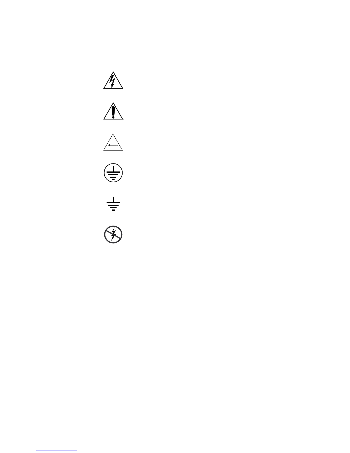
Symbols on the Product
The following symbols may appear on the product:
Indicates that dangerous high voltage is present within the
equipment enclosure that may be of sufficient magnitude to
constitute a risk of electric shock.
Indicates that user, operator or service technician should refer
to product manual(s) for important operating, maintenance,
or service instructions.
This is a prompt to note fuse rating when replacing fuse(s).
The fuse referenced in the text must be replaced with one
having the ratings indicated.
Identifies a protective grounding terminal which must be connected to earth ground prior to making any
connections.
other equipment
Warnings
Identifies an external protective grounding terminal which
may be connected to earth ground as a supplement to an
internal grounding terminal.
Indicates that static sensitive components are present which
may be damaged by electrostatic discharge. Use anti-static
procedures, equipment and surfaces during servicing.
The following warning statements identify conditions or practices that can
result in personal injury or loss of life:
Dangerous voltage or current may be present — Disconnect power and remove
battery (if applicable) before removing protective panels, soldering, or
replacing components.
Do not service alone — Do not internally service this product unless another
person capable of rendering first aid and resuscitation is present.
Remove jewelry — Prior to servicing, remove jewelry such as rings, watches,
and other metallic objects.
Avoid exposed circuitry — Do not touch exposed connections, components or
circuitry when power is present.
10 Kayenne XL Package — Installation and Service Manual
Page 11

Safety Summary
Use proper power cord — Use only the power cord supplied or specified for
this product.
Ground product — Connect the grounding conductor of the power cord to
earth ground.
Operate only with covers and enclosure panels in place — Do not operate this
product when covers or enclosure panels are removed.
Use correct fuse — Use only the fuse type and rating specified for this
product.
Use only in dry environment — Do not operate in wet or damp conditions.
Use only in non-explosive environment — Do not operate this product in an
explosive atmosphere.
High leakage current may be present — Earth connection of product is essential
before connecting power.
Dual power supplies may be present — Be certain to plug each power supply
cord into a separate branch circuit employing a separate service ground.
Disconnect both power supply cords prior to servicing.
Cautions
Double pole neutral fusing — Disconnect mains power prior to servicing.
Use proper lift points — Do not use door latches to lift or move equipment.
Avoid mechanical hazards — Allow all rotating devices to come to a stop before
servicing.
The following caution statements identify conditions or practices that can
result in damage to equipment or other property:
Use correct power source — Do not operate this product from a power source
that applies more than the voltage specified for the product.
Use correct voltage setting — If this product lacks auto-ranging power sup-
plies, before applying power ensure that the each power supply is set to
match the power source.
Provide proper ventilation — To prevent product overheating, provide equip-
ment ventilation in accordance with installation instructions.
Use anti-static procedures — Static sensitive components are present which
may be damaged by electrostatic discharge. Use anti-static procedures,
equipment and surfaces during servicing.
Kayenne XL Package — Installation and Service Manual 11
Page 12

Safety Summary
Do not operate with suspected equipment failure — If you suspect product damage
or equipment failure, have the equipment inspected by qualified service
personnel.
Ensure mains disconnect — If mains switch is not provided, the power cord(s)
of this equipment provide the means of disconnection. The socket outlet
must be installed near the equipment and must be easily accessible. Verify
that all mains power is disconnected before installing or removing power
supplies and/or options.
Route cable properly — Route power cords and other cables so that they ar not
likely to be damaged. Properly support heavy cable bundles to avoid con
nector damage.
Use correct power supply cords — Power cords for this equipment, if provided,
meet all North American electrical codes. Operation of this equipment at
voltages exceeding 130 VAC requires power supply cords which comply
with NEMA configurations. International power cords, if provided, have
the approval of the country of use.
Use correct replacement battery — This product may contain batteries. To
reduce the risk of explosion, check polarity and replace only with the same
or equivalent type recommended by manufacturer. Dispose of used bat
teries according to the manufacturer’s instructions.
-
-
Troubleshoot only to board level — Circuit boards in this product are densely
populated with surface mount technology (SMT) components and applica
tion specific integrated circuits (ASICS). As a result, circuit board repair at
the component level is very difficult in the field, if not impossible. For war
ranty compliance, do not troubleshoot systems beyond the board level.
-
-
12 Kayenne XL Package — Installation and Service Manual
Page 13

Sicherheit – Überblick
Lesen und befolgen Sie die wichtigen Sicherheitsinformationen dieses
Abschnitts. Beachten Sie insbesondere die Anweisungen bezüglich
Brand-, Stromschlag- und Verletzungsgefahren. Weitere spezifische, hier
nicht aufgeführte Warnungen finden Sie im gesamten Handbuch.
WARNUNG Alle Anweisungen in diesem Handbuch, die das Abnehmen der
Geräteabdeckung oder des Gerätegehäuses erfordern, dürfen nur von
qualifiziertem Servicepersonal ausgeführt werden. Um die
Stromschlaggefahr zu verringern, führen Sie keine Wartungsarbeiten
außer den in den Bedienungsanleitungen genannten Arbeiten aus, es sei
denn, Sie besitzen die entsprechende Qualifikationen für diese Arbeiten.
Sicherheit – Begriffe und Symbole
Safety Summary
In diesem Handbuch verwendete Begriffe
Sicherheitsrelevante Hinweise können in diesem Handbuch in der folgenden Form auftauchen:
WARNUNG Warnungen weisen auf Situationen oder Vorgehensweisen hin, die
Verletzungs- oder Lebensgefahr bergen.
VORSICHT Vorsichtshinweise weisen auf Situationen oder Vorgehensweisen hin, die zu
Schäden an Ausrüstungskomponenten oder anderen Gegenständen oder
zum zeitweisen Ausfall wichtiger Komponenten in der Arbeitsumgebung
führen können.
Hinweise am Produkt
Die folgenden Hinweise können sich am Produkt befinden:
GEFAHR — Wenn Sie diesen Begriff lesen, besteht ein unmittelbares Verlet-
zungsrisiko.
WARNUNG — Wenn Sie diesen Begriff lesen, besteht ein mittelbares Verlet-
zungsrisiko.
VORSICHT — Es besteht ein Risiko für Objekte in der Umgebung, den Mixer
selbst oder andere Ausrüstungskomponenten.
Kayenne XL Package — Installation and Service Manual 13
Page 14
Safety Summary
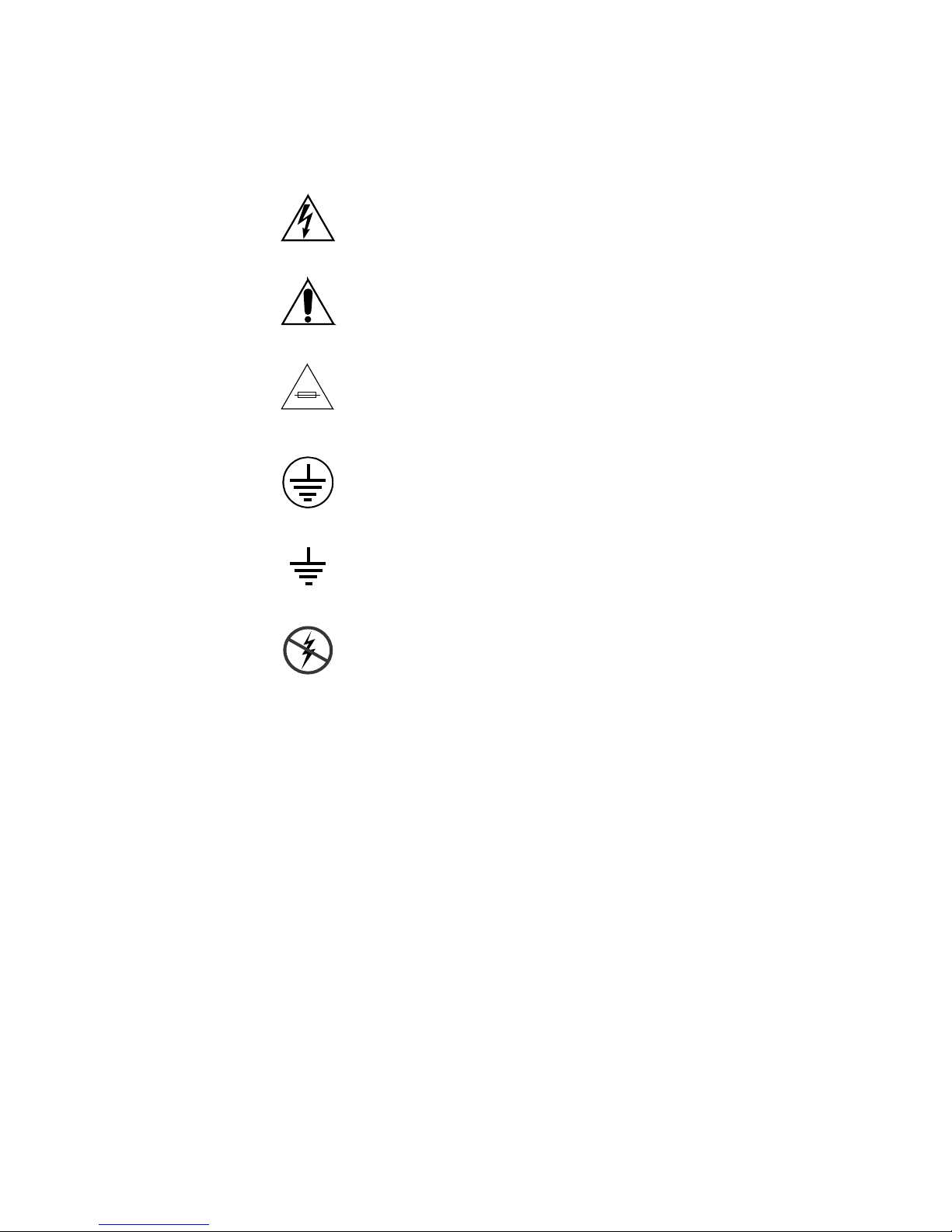
Symbole am Produkt
Die folgenden Symbole können sich am Produkt befinden:
Weist auf eine gefährliche Hochspannung im Gerätegehäuse
hin, die stark genug sein kann, um eine Stromschlaggefahr
darzustellen.
Weist darauf hin, dass der Benutzer, Bediener oder Servicetechniker wichtige Bedienungs-, W
weisungen in den Produkthandbüchern lesen sollte.
Dies ist eine Aufforderung, beim Wechsel von Sicherungen
auf deren Nennwert zu achten. Die im Text angegebene Sicherung muss durch eine Sicherung erse
angegebenen Nennwerte besitzt.
Weist auf eine Schutzerdungsklemme hin, die mit dem
Erdungskontakt verbunden werden muss, bevor weitere Ausrüstungskomponenten angeschlossen werden.
artungs- oder Servicean-
tzt werden, die die
Warnungen
Weist auf eine externe Schutzerdungsklemme hin, die als
Ergänzung zu einem internen Erdungskontakt an die Erde
angeschlossen werden kann.
Weist darauf hin, dass es statisch empfindliche Komponenten
gibt, die durch eine elektrostatische Entladung beschädigt
werden können. Verwenden Sie antistatische Prozeduren,
Ausrüstung und Oberflächen während der Wartung.
Die folgenden Warnungen weisen auf Bedingungen oder Vorgehensweisen
hin, die Verletzungs- oder Lebensgefahr bergen:
Gefährliche Spannungen oder Ströme — Schalten Sie den Strom ab, und ent-
fernen Sie ggf. die Batterie, bevor sie
oder Komponenten austauschen.
Servicearbeiten nicht alleine ausführen — Führen Sie interne Servicearbeiten nur
aus, wenn eine weitere Person anwesend ist, die erste Hilfe leisten und
Wiederbelebungsmaßnahmen einleiten kann.
Schutzabdeckungen abnehmen, löten
Schmuck abnehmen — Legen Sie vor Servicearbeiten Schmuck wie Ringe,
Uhren und andere metallische Objekte ab.
14 Kayenne XL Package — Installation and Service Manual
Page 15

Safety Summary
Keine offen liegenden Leiter berühren — Berühren Sie bei eingeschalteter Strom-
zufuhr keine offen liegenden Leitungen, Komponenten oder Schaltungen.
Richtiges Netzkabel verwenden — Verwenden Sie nur das mitgelieferte Netzk-
abel oder ein Netzkabel, das den Spezifikationen für dieses Produkt
entspricht.
Gerät erden — Schließen Sie den Erdleiter des Netzkabels an den Erdung-
skontakt an.
Gerät nur mit angebrachten Abdeckungen und Gehäuseseiten betreiben — Schalten Sie
dieses Gerät nicht ein, wenn die Abdeckungen oder Gehäuseseiten entfernt
wurden.
Richtige Sicherung verwenden — Verwenden Sie nur Sicherungen, deren Typ
und Nennwert den Spezifikationen für dieses Produkt entsprechen.
Gerät nur in trockener Umgebung verwenden — Betreiben Sie das Gerät nicht in
nassen oder feuchten Umgebungen.
Gerät nur verwenden, wenn keine Explosionsgefahr besteht — Verwenden Sie dieses
Produkt nur in Umgebungen, in denen keinerlei Explosionsgefahr besteht.
Hohe Kriechströme — Das Gerät muss vor dem Einschalten unbedingt geerdet
werden.
Doppelte Spannungsversorgung kann vorhanden sein — Schließen Sie die beiden
Anschlußkabel an getrennte Stromkreise an. Vor Servicearbeiten sind beide
Anschlußkabel vom Netz zu trennen.
Zweipolige, neutrale Sicherung — Schalten Sie den Netzstrom ab, bevor Sie mit
den Servicearbeiten beginnen.
Fassen Sie das Gerät beim Transport richtig an — Halten Sie das Gerät beim Trans-
port nicht an Türen oder anderen beweglichen Teilen fest.
Gefahr durch mechanische Teile — Warten Sie, bis der Lüfter vollständig zum
Halt gekommen ist, bevor Sie mit den Servicearbeiten beginnen.
Vorsicht
Die folgenden Vorsichtshinweise weisen auf Bedingungen oder Vorgehensweisen hin, die zu Schäden an Ausrüstungskomponenten oder
anderen Gegenständen führen können:
Gerät nicht öffnen — Durch das unbefugte Öffnen wird die Garantie ungültig.
Richtige Spannungsquelle verwenden — Betreiben Sie das Gerät nicht an einer
Spannungsquelle, die eine höhere Spannung liefert als in den Spezifika
tionen für dieses Produkt angegeben.
Kayenne XL Package — Installation and Service Manual 15
-
Page 16

Safety Summary
Gerät ausreichend belüften — Um eine Überhitzung des Geräts zu vermeiden,
müssen die Ausrüstungskomponenten entsprechend den Installationsan
weisungen belüftet werden. Legen Sie kein Papier unter das Gerät. Es
könnte die Belüftung behindern. Platzieren Sie das Gerät auf einer ebenen
Oberfläche.
Antistatische Vorkehrungen treffen — Es gibt statisch empfindliche Kompo-
nenten, die durch eine elektrostatische Entladung beschädigt werden können. Verwenden Sie antistatische Prozeduren, Ausrüstung und
Oberflächen während der Wartung.
CF-Karte nicht mit einem PC verwenden — Die CF-Karte ist speziell formatiert.
Die auf der CF-Karte gespeicherte Software könnte gelöscht werden.
Gerät nicht bei eventuellem Ausrüstungsfehler betreiben — Wenn Sie einen Produk-
tschaden oder Ausrüstungsfehler vermuten, lassen Sie die Komponente
von einem qualifizierten Servicetechniker untersuchen.
Kabel richtig verlegen — Verlegen Sie Netzkabel und andere Kabel so, dass Sie
nicht beschädigt werden. Stützen Sie schwere Kabelbündel ordnungs
gemäß ab, damit die Anschlüsse nicht beschädigt werden.
-
-
Richtige Netzkabel verwenden — Wenn Netzkabel mitgeliefert wurden, erfüllen
diese alle nationalen elektrischen Normen. Der Betrieb dieses Geräts mit
Spannungen über 130 V AC erfordert Netzkabel, die NEMA-Konfigura
tionen entsprechen. Wenn internationale Netzkabel mitgeliefert wurden,
sind diese für das Verwendungsland zugelassen.
Richtige Ersatzbatterie verwenden — Dieses Gerät enthält eine Batterie. Um die
Explosionsgefahr zu verringern, prüfen Sie die Polarität und tauschen die
Batterie nur gegen eine Batterie desselben Typs oder eines gleichwertigen,
vom Hersteller empfohlenen Typs aus. Entsorgen Sie gebrauchte Batterien
entsprechend den Anweisungen des Batterieherstellers.
Das Gerät enthält keine Teile, die vom Benutzer gewartet werden können.
Wenden Sie sich bei Problemen bitte an den nächsten Händler.
-
16 Kayenne XL Package — Installation and Service Manual
Page 17

Consignes de sécurité
Il est recommandé de lire, de bien comprendre et surtout de respecter les
informations relatives à la sécurité qui sont exposées ci-après, notamment
les consignes destinées à prévenir les risques d’incendie, les décharges élec
triques et les blessures aux personnes. Les avertissements complémentaires, qui ne sont pas nécessairement repris ci-dessous, mais présents dans
toutes les sections du manuel, sont également à prendre en considération.
AVERTISSEMENT Toutes les instructions présentes dans ce manuel qui concernent
l’ouverture des capots ou des logements de cet équipement sont
destinées exclusivement à des membres qualifiés du personnel de
maintenance. Afin de diminuer les risques de décharges
électriques, ne procédez à aucune intervention d’entretien autre
que celles contenues dans le manuel de l’utilisateur, à moins que
vous ne soyez habilité pour le faire.
Safety Summary
-
Consignes et symboles de sécurité
Termes utilisés dans ce manuel
Les consignes de sécurité présentées dans ce manuel peuvent apparaître
sous les formes suivantes:
AVERTISSEMENT Les avertissements signalent des conditions ou des pratiques
susceptibles d’occasionner des blessures graves, voire même
fatales.
ATTENTION Les mises en garde signalent des conditions ou des pratiques
susceptibles d’occasionner un endommagement à l’équipement ou
aux installations, ou de rendre l’équipement temporairement non
opérationnel, ce qui peut porter préjudice à vos activités.
Signalétique apposée sur le produit
La signalétique suivante peut être apposée sur le produit:
DANGER — risque de danger imminent pour l’utilisateur.
AVERTISSEMENT — Risque de danger non imminent pour l’utilisateur.
MISE EN GARDE — Risque d’endommagement du produit, des installations
ou des autres équipements.
Kayenne XL Package — Installation and Service Manual 17
Page 18
Safety Summary
Symboles apposés sur le produit
Les symboles suivants peut être apposés sur le produit:
Signale la présence d’une tension élevée et dangereuse dans le
boîtier de l’équipement ; cette tension peut être suffisante
pour constituer un r
Signale que l’utilisateur, l’opérateur ou le technicien de maintenance doit faire référence au(
naissance des instructions d’uti
d’entretien.
Il s’agit d’une invite à prendre note du calibre du fusible lors
du remplacement de ce dernier. Le fusible auquel il est fait
référence dans le texte doit être remplacé par un fusible du
même calibre.
Identifie une borne de protection de mise à la masse qui doit
être raccordée correctement avant de procéder au raccordement des autres équipements.
isque de décharge électrique.
x) manuel(s) pour prendre con-
lisation, de maintenance ou
Avertissements
Identifie une borne de protection de mise à la masse qui peut
être connectée en tant que borne de mise à la masse supplémentaire.
Signale la présence de composants sensibles à l’électricité statique et qui sont susceptibles d’ê
décharge électrostatique. Utilisez des procédures, des équipements et des surfaces antistatique
d’entretien.
Les avertissements suivants signalent des conditions ou des pratiques susceptibles d’occasionner des blessures graves, voire même fatales:
Présence possible de tensions ou de courants dangereux — Mettez hors tension,
débranchez et retirez la pile (le cas échéant) avant de déposer les couvercles
de protection, de défaire une soudure ou de remplacer des composants.
Ne procédez pas seul à une intervention d’entretien — Ne réalisez pas une interven-
tion d’entretien interne sur ce produit
pour fournir les premiers soins en cas d’accident.
si une personne n’est pas présente
tre endommagés par une
s durant les interventions
Retirez tous vos bijoux — Avant de procéder à une intervention d’entretien,
retirez tous vos bijoux, notamment les bagues, la montre ou tout autre objet
métallique.
18 Kayenne XL Package — Installation and Service Manual
Page 19

Safety Summary
Évitez tout contact avec les circuits exposés — Évitez tout contact avec les connex-
ions, les composants ou les circuits exposés s’ils sont sous tension.
Utilisez le cordon d’alimentation approprié — Utilisez exclusivement le cordon
d’alimentation fourni avec ce produit ou spécifié pour ce produit.
Raccordez le produit à la masse — Raccordez le conducteur de masse du cordon
d’alimentation à la borne de masse de la prise secteur.
Utilisez le produit lorsque les couvercles et les capots sont en place — N’utilisez pas
ce produit si les couvercles et les capots sont déposés.
Utilisez le bon fusible — Utilisez exclusivement un fusible du type et du
calibre spécifiés pour ce produit.
Utilisez ce produit exclusivement dans un environnement sec — N’utilisez pas ce
produit dans un environnement humide.
Utilisez ce produit exclusivement dans un environnement non explosible — N’utilisez
pas ce produit dans un environnement dont l’atmosphère est explosible.
Présence possible de courants de fuite — Un raccordement à la masse est indis-
pensable avant la mise sous tension.
Mises en garde
Deux alimentations peuvent être présentes dans l’équipement — Assurez vous que
chaque cordon d’alimentation est raccordé à des circuits de terre séparés.
Débranchez les deux cordons d’alimentation avant toute intervention.
Fusion neutre bipolaire — Débranchez l’alimentation principale avant de pro-
céder à une intervention d’entretien.
Utilisez les points de levage appropriés — Ne pas utiliser les verrous de la porte
pour lever ou déplacer l’équipement.
Évitez les dangers mécaniques — Laissez le ventilateur s’arrêter avant de pro-
céder à une intervention d’entretien.
Les mises en garde suivantes signalent les conditions et les pratiques susceptibles d’occasionner des endommagements à l’équipement et aux installations:
N’ouvrez pas l’appareil — Toute ouverture prohibée de l’appareil aura pour
effet d’annuler la garantie.
Utilisez la source d’alimentation adéquate — Ne branchez pas ce produit à une
source d’alimentation qui utilise une tension supérieure à la tension nomi
nale spécifiée pour ce produit.
Kayenne XL Package — Installation and Service Manual 19
-
Page 20

Safety Summary
Assurez une ventilation adéquate — Pour éviter toute surchauffe du produit,
assurez une ventilation de l’équipement conformément aux instructions
d’installation. Ne déposez aucun document sous l’appareil — ils peuvent
gêner la ventilation. Placez l’appareil sur une surface plane.
Utilisez des procédures antistatiques - Les composants sensibles à l’électricité
statique présents dans l’équipement sont susceptibles d’être endommagés
par une décharge électrostatique. Utilisez des procédures, des équipements
et des surfaces antistatiques durant les interventions d’entretien.
N’utilisez pas la carte CF avec un PC — La carte CF a été spécialement formatée.
Le logiciel enregistré sur la carte CF risque d’être effacé.
N’utilisez pas l’équipement si un dysfonctionnement est suspecté — Si vous sus-
pectez un dysfonctionnement du produit, faites inspecter celui-ci par un
membre qualifié du personnel d’entretien.
Acheminez les câbles correctement — Acheminez les câbles d’alimentation et les
autres câbles de manière à ce qu’ils ne risquent pas d’être endommagés.
Supportez correctement les enroulements de câbles afin de ne pas endom
mager les connecteurs.
-
Utilisez les cordons d’alimentation adéquats — Les cordons d’alimentation de cet
équipement, s’ils sont fournis, satisfont aux exigences de toutes les régle
mentations régionales. L’utilisation de cet équipement à des tensions
dépassant les 130
aux exigences des configurations NEMA. Les cordons internationaux, s’ils
sont fournis, ont reçu l’approbation du pays dans lequel l’équipement est
utilisé.
Utilisez une pile de remplacement adéquate — Ce produit renferme une pile. Pour
réduire le risque d’explosion, vérifiez la polarité et ne remplacez la pile que
par une pile du même type, recommandée par le fabricant. Mettez les piles
usagées au rebut conformément aux instructions du fabricant des piles.
Cette unité ne contient aucune partie qui peut faire l’objet d’un entretien
par l’utilisateur. Si un problème survient, veuillez contacter votre distribu
teur local.
V en c.a. requiert des cordons d’alimentation qui satisfont
-
-
20 Kayenne XL Package — Installation and Service Manual
Page 21

Introduction
General
Using Open Sources Software
This product contains free software code released under the GNU General
Public License (GPL) Version 2 (available at
http://www.gnu.org/licenses/gpl.txt) and free software released under
the GNU Lesser General Public License (LGPL) Version 2.1 (available at
http://www.gnu.org/licenses/lgpl.txt) and free software released under
the GNU Lesser General Public License (LGPL) Version 3 (available at
http://www.gnu.org/licenses/lgpl.txt). Anyone may obtain from us a
copy of the source code for those free software packages. The full texts of
the GPLv2, LGPLv2.1, LGPLv3 and GPLv3 are included on this documen
tation/CD-ROM. The source packages for these programs are available for
download at http://www.thomson.net/open-software. Those individuals
without Internet access may request that a CD-ROM or DVD containing the
source code be sent to them by mail. To reimburse the expenses incurred by
creation, handling and postage, we will charge a €12 fee. To request a CD
ROM or DVD of the source code, send an e-mail to our Open Software Rep
resentative jean-pierre.fourche@thomson.net or mail the request, with payment, to Jean-Pierre Fourche, Open Software Representative, Thomson, 46
Quai Alphonse Le Gallo 92100 Boulogne-Billancourt, France.”
Section 1
-
-
Copyrights
BusyBox is licensed under the GNU General Public License, version 2
GNU LESSER GENERAL PUBLIC LICENSE Version 2.1, February 1999 Copyright
(C) 1991, 1999 Free Software Foundation, Inc. 59 Temple Place, Suite 330,
Boston, MA 02111-1307 USA
Kayenne XL Package — Installation and Service Manual 21
Page 22

Section 1 — Introduction
8623266_06
KayakHD-XL 8-RU
Video Processing Frame
KayakHD-XL 4-RU
Video Processing Frame
Overview
The Grass Valley Kayak HD family of multi-format digital production
switchers provides powerful, ground-breaking features designed to meet
the widest range of requirements for live studio, mobile, and post-produc
tion applications. Available in configurations ranging from 1-ME to
4.5-MEs, Kayenne XL Packages combine features available in the Grass
Valley XtenDD, Kalypso and Kayak HD switchers along with additional
capabilities previously unavailable in any video production switcher by
any manufacturer.
Kayenne XL Package
A wide variety of possible system configurations exist to meet different
customer requirements.
The package contains:
• Kayenne XL Control Panel
-
• Kayak HD Mainframe
• Software Licenses
Kayak HD Video Processor Frames
The Kayak HD Video Processor Frame comes in two sizes. The 8-RU full
size frame supports up to 4.5 ME systems. The 4-RU compact frame sup
ports 1-ME through 2.5-ME Kayak HD systems (Figure 1). The number of
boards present in the Kayak HD frame determines the number of MEs
available, as well as the number of video inputs, outputs, GPIs and Tally.
Figure 1. Kayak HD Video Processor Frames
-
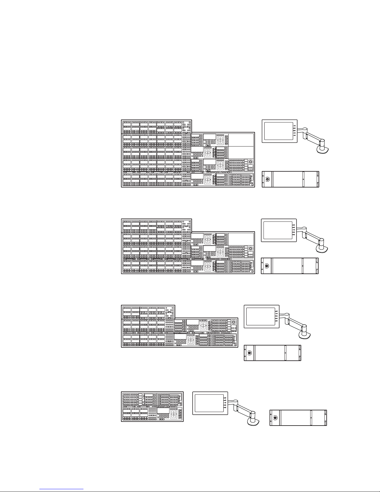
Kayenne XL Control Surfaces
A Kayenne XL control surface consists of a Control Panel, a Menu Panel
with an included articulated support arm, a Panel Control Unit frame, and
22 Kayenne XL Package — Installation and Service Manual
optional Satellite panels. This control surface has an innovative modular
Page 23
Kayenne XL Package
Menu Panel
Menu Panel
Articulated
Arm
8623266_02
Panel Control Unit (PCU)
3-ME 35 Control Panel
Optional
Module
design, permitting customized operator control layouts. Representative
Kayenne XL control surfaces are shown in the following illustrations.
Control panel options are available that do not include the menu panel or
the PCU for adding a panel using one PCU. Up to 8 stripes are supported
on one PCU.
Figure 2. Kayenne XL 4-ME 35 Control Surface
4-ME 35 Control Panel Menu Panel
Optional
Module
Optional
Module
Panel Control Unit (PCU)
Figure 3. Kayenne XL 3-ME 35 Control Surface
Menu Panel
Articulated
Arm
8623266_01
Figure 4. Kayenne XL 2-ME 25 Control Surface
2-ME 25 Control Panel
Figure 5. Kayenne XL 1-ME 15 Control Surface
1-ME 15 Control Panel
Menu Panel
Menu Panel
Panel Control Unit (PCU)
Menu Panel
Articulated
Arm
Panel Control Unit (PCU)
Menu Panel
Articulated
Arm
8623266_03
Kayenne XL Package — Installation and Service Manual 23
8623266_04
Page 24
Section 1 — Introduction
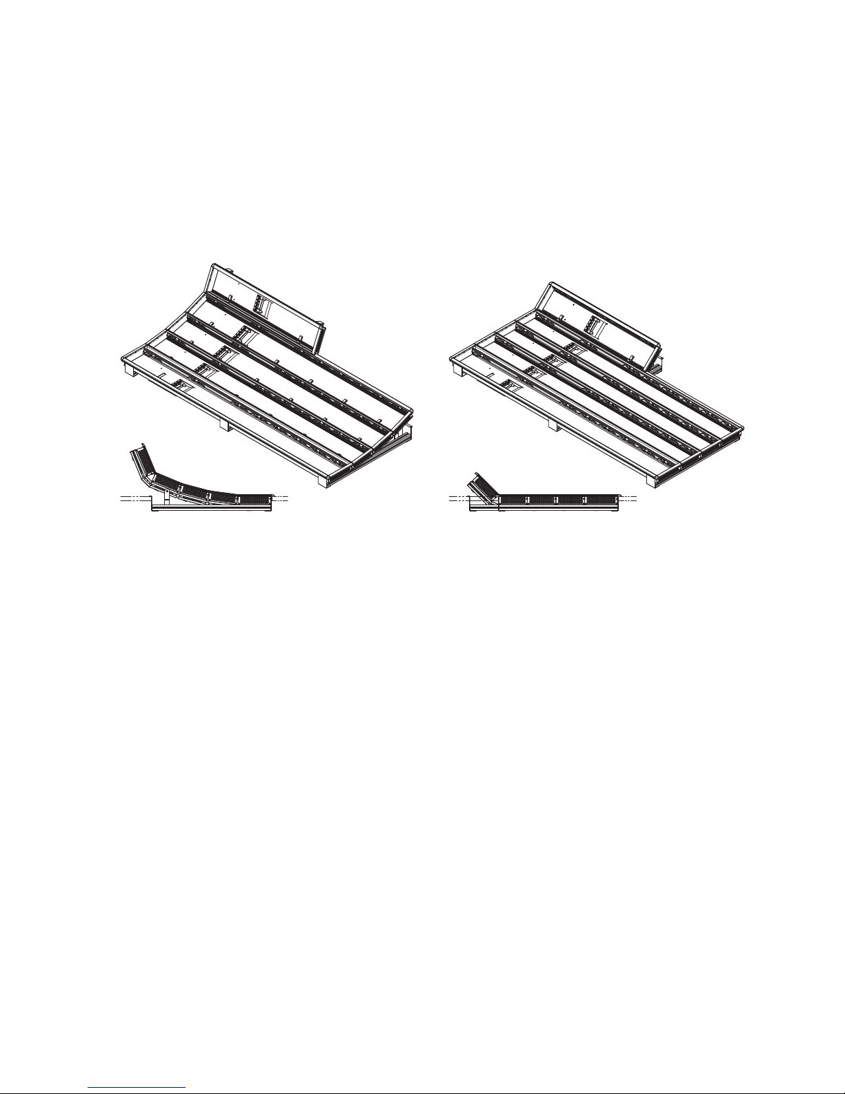
Flat or Curved Control Panel Orientation
Curved Control Panel Assembly
The main Kayenne XL Control Panel supports different physical orientations. Besides a conventional flat surface, a special support design permits
a curved working surface, where the MEs progressively tilt for improved
ergonomics (
Figure 6. Flat and Curved Control Surface Installations
Figure 6).
Straight Control Panel Assembly
Control Panel Stripes
The main Kayenne XL Control Panel is organized into from two to five
stripes. Each stripe consists of a tray that accepts drop-in modules. An ME
stripe has a module for Source Selection, Transition, and individual EMEM
control. Additional Master EMEM, Machine Control, Multi-Function, and
Local Aux modules are dropped in to complete the control surface func
tionality.
Control Panel Modules
The following Kayenne XL Control Panel and Satellite modules are available:
• KAYN-PNL-TRM - Transition Module, used to control ME transitions
and keying.
• KAYN-PNL-LEM - Local EMEM Module, used to control EMEM effects
on that ME stripe.
• KAYN-PNL-MEM - Master EMEM Module, used for delegated EMEM
control of any or all system MEs.
8623266_36
-
• KAYN-PNL-MFM - Multi-Function Module, used for delegated control
of various functions
• KAYN-PNL-DCM - Device Control Module, used for internal and
external device control.
24 Kayenne XL Package — Installation and Service Manual
Page 25
• KAYN-PNL-SRC-35, 25, 15 - Source Module, available in 35, 25, and 15
button widths, used for ME source selection.
• KAYN-PNL-BAR-35, 25, 15 - Panel Bar, available in three sizes to match
various control panel widths, used for device control and macros.
• KAYN-PNL-AUX-35, 25, 15 - Local Aux Module, available in 35, 25, and
15 button widths, used for Aux Bus control.
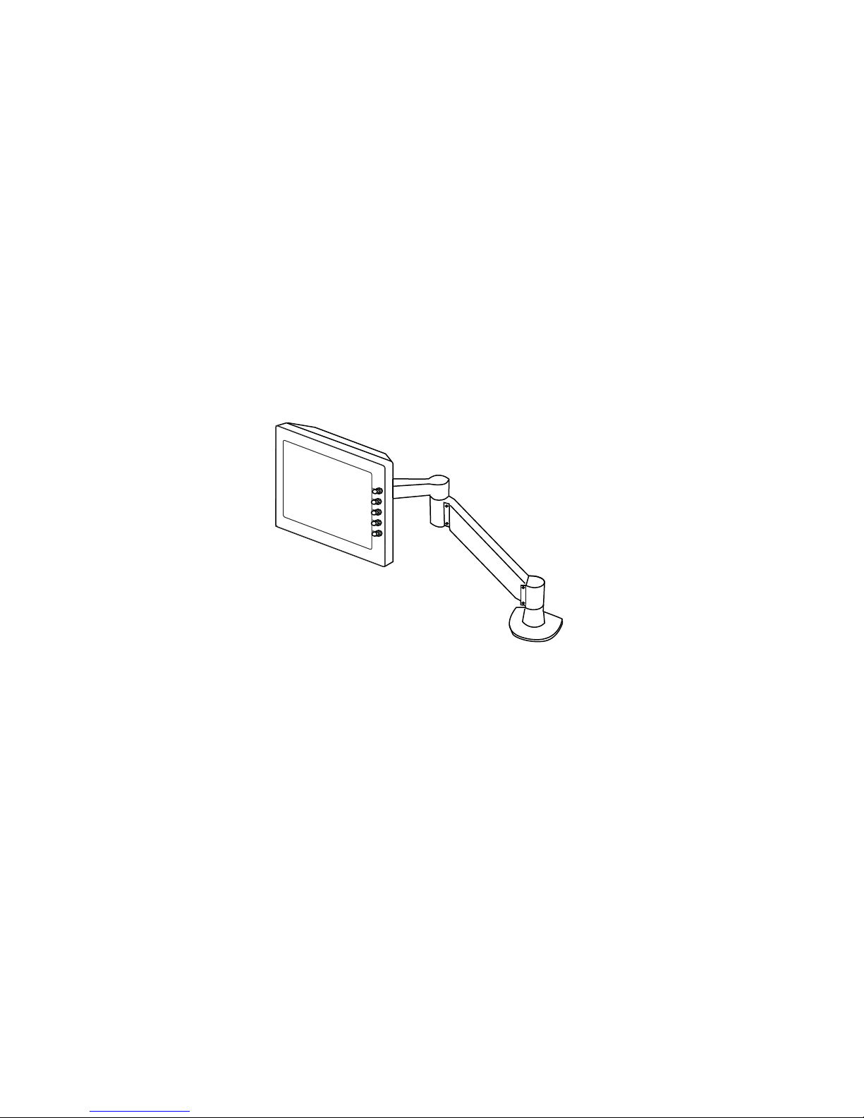
Touch Screen Menu Panel and PC Menu Control
Each Kayenne XL control surface includes a Menu Panel that features a
wide format touch screen display. An articulated arm is also included,
offering a wide variety of installation options (
equipped with standard VESA-75 threads, compatible with this and many
other mounting devices.
Figure 7. Menu Panel with Articulated Arm
Kayenne XL Package
Figure 7). The Menu panel is
An additional touch screen Kayenne XL Menu Panel is available as an
option. It is also possible to run the Kayenne XL menu application on a
standard PC, permitting mouse and keyboard control from a laptop, or
remote control from any location on the network.
Panel Control Unit
The Kayenne XL Control Panel and Touch Screen Menu panel(s) are
powered with a separate rack mount Panel Control Unit (PCU). Control
surface processing and communications are handled by this unit, which
permits the hot-swapping of individual control surface components, if nec
essary, while the rest of the system remains operational. This also allows for
the elimination of cooling fans in the Control Panel and Touch Screen Menu
Panel, making for quiet system operation.
8623266_05
-
Kayenne XL Package — Installation and Service Manual 25
Page 26

Section 1 — Introduction
Satellite Panels
Redundant Power Supplies
Two satellite panel options are available for mounting control panel
modules outside of the main control panel. One option supports one
module and another options supports two modules. Each consumes one
PCU port.
Optional built-in redundant power supplies are available for the Kayak HD
Frame 4-RU and 8-RU Frames. A second power supply is included, stan
dard, in the Kayenne XL Panel Control Unit.
-
26 Kayenne XL Package — Installation and Service Manual
Page 27

Supported Control Protocols
• VTRs (BVW-75)
• AMP (Advanced Media Protocol). For Profile PVS, XP, K2, M Series,
and Turbo DDRs. Available for RS422 Serial or Ethernet.
• Servers (Louth VDCP, Odetics)
• Routers/Routing Control Systems (Trinix™, Venus™, Triton™, and
third party routers; Jupiter™ and Encore™ router control systems)
• Control Systems (Grass Valley Andromeda™ and third-party systems)
• Grass Valley Under Monitor Displays (Serial tally for UMD. Requires
Grass Valley Andromeda™ system or third-part tally box such as Tally
Display Corp. or Image Video.)
• Grass Valley external Remote AUX Panels (CP-300 Series)
• ESAM II for audio-follow-video applications
• Edit controllers (native and Grass Valley Model 100 and 200)
Supported Control Protocols
Kayenne XL Package — Installation and Service Manual 27
Page 28
Section 1 — Introduction
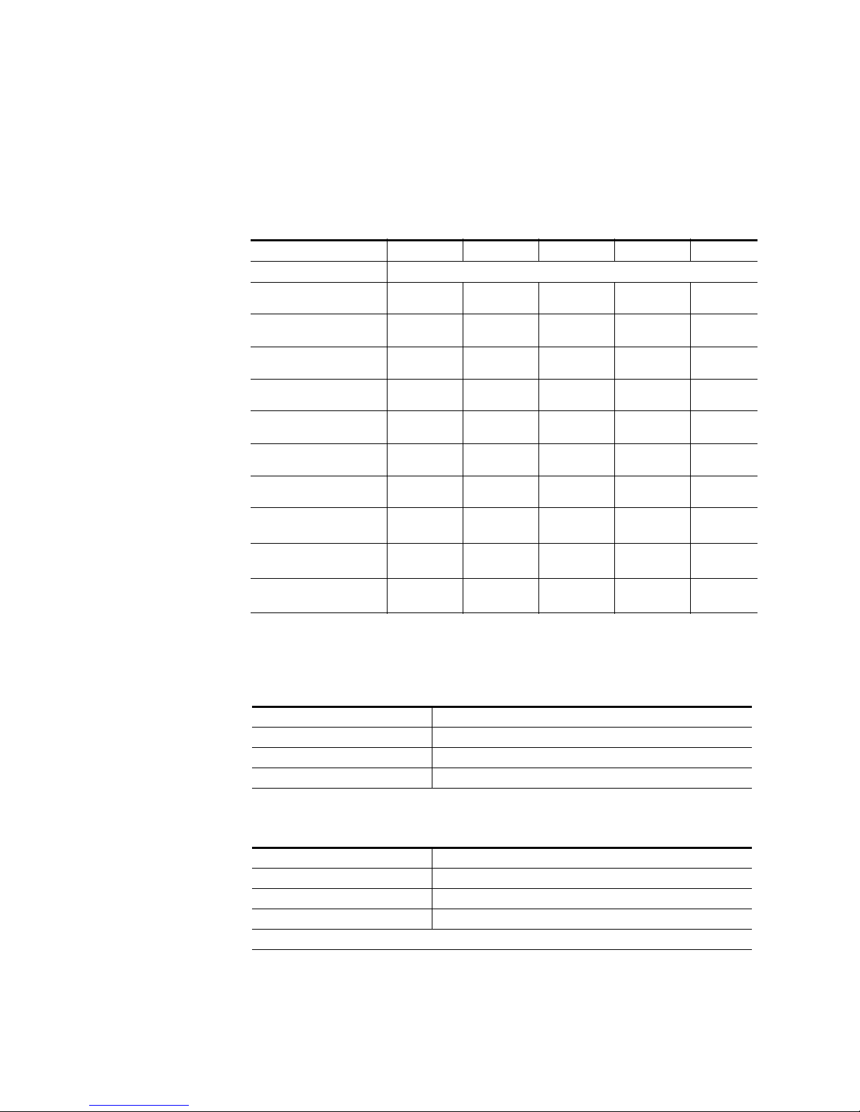
Specifications
Kayenne XL Package
Table 1. Kayenne XL Mechanical Specifications
Component Depth (Flat) Width Height (Flat) Weight
Control Panels
4.5ME-35, w/o Aux Panel
3.5ME-35, w/o Aux Panel
2.5ME-25, w/o Aux Panel
1.5ME-15, w/o Aux Panel
Local Aux Panel-35
Local Aux Panel-25
Menu Panel
Panel Control Unit
(PCU)
Kayak HD
4-RU Frame
Kayak HD
8-RU Frame
a
All weights approximate.
84.3 mm
(3.32 in.)
84.3 mm
(3.32 in.)
84.3 mm
(3.32 in.)
84.3 mm
(3.32 in.)
84.3 mm
(3.32 in.)
84.3 mm
(3.32 in.)
91.7 mm
(3.612 in.)
588.52 mm
(23.17 in.)
546.10 mm
(21.5 in.)
522.73 mm
(20.58 in.)
1533.7 mm
(60.38 in.)
1533.7 mm
(60.38 in.)
1341.7 mm
(52.82 in.)
813.7 mm
621.7 mm
417.85 mm
(16.45 in.)
482.60 mm
(19 in.)
482.60 mm
(19 in.)
482.60 mm
(19 in.)
651.3 mm
(25.6 in.)
270.10 mm
(10.63 in.)
132.59 mm
(5.22 in.)
177.80 mm
(7 in.)
441.96 mm
(17.4 in.)
17.69 kg
(39 lbs)
30.39 kg
(67 lbs)
a
Rack Units
n/a
n/a
n/a
n/a
n/a
n/a
n/a
3
4
8
Table 2. Environmental
Storage temperature -20 to 70 deg C (-4 to 158 deg F)
Operating temperature 0 to 40 deg C (68 to 104 deg F)
Relative humidity 0-95% (non-condensing)
Electromagnetic environment E2 (according to EN55103-1, -2)
Table 3. Network Connections
Type of connection 10/1000 Base T
Protocol TCP(UDP)/IP, Auto speed detection. Auto crossover cable configuration.
Cable and connectors CAT5 UTP, RJ45 connectors;
Max. Cable Length 100m / 300ft
1 Frame and up to 4 PCUs connect without of external hub/switch. Each Frame and PCU has internal Ethernet switch.
28 Kayenne XL Package — Installation and Service Manual
Page 29
Specifications
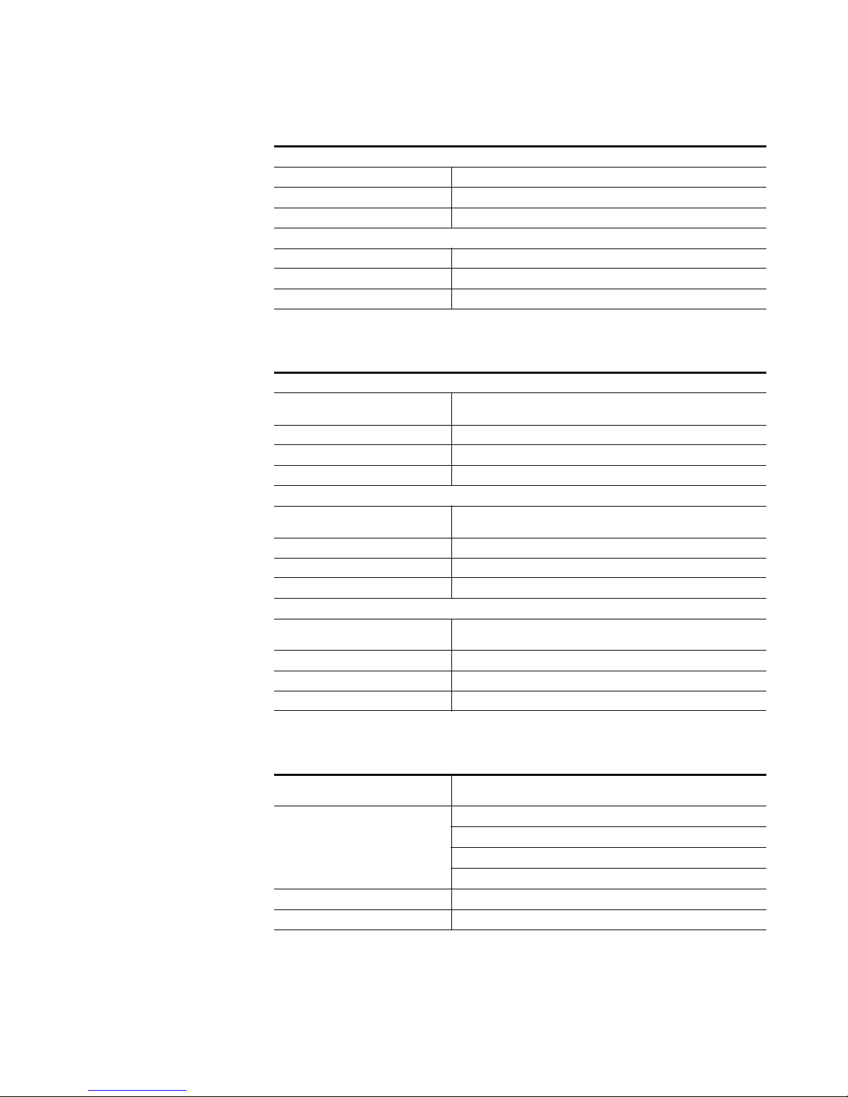
Table 4. PCU Interconnects
Control Panel - PCU Connections
Cable and connectors Custom 7 Pin D style
Number of connections 1 for each Control Panel Stripe, Local Aux Panel, and Satellite Panel
Max. Interconnect Cable Length 15m / 50ft (7.5m / 25ft cable length also available)
Touch Screen Menu Panel - PCU Connection
Cable and connectors Custom 17 Pin D style
Number of connections 1 for each Touch Screen Menu Panel (2 maximum)
Max. Interconnect Cable Length 15m / 50ft (7.5m / 25ft cable length also available)
Table 5. Power
4-RU Frame
Line voltage
Line frequency 50/60Hz +/- 5%
Power consumption max. 400W
Leakage current < 2.5 mA
8-RU Frame
Line voltage
Line frequency 50/60Hz +/- 5%
Power consumption max. 800W
Leakage current < 2.5 mA
Panel Control Unit (required for Control Panel and Touch Screen Menu Panel Operation)
Line voltage
Line frequency 50/60Hz +/- 5%
Power consumption max. 400W
Leakage current < 2.5 mA
100V-240V AC +/-10% autorange, power factor corrected. Automatic linevoltage sensing for 120V and 240V sources.
100V-240V AC +/-10% autorange, power factor corrected. Automatic linevoltage sensing for 120V and 240V sources.
100V-240V AC +/-10% autorange, power factor corrected. Automatic linevoltage sensing for 120V and 240V sources.
Table 6. Serial Digital Video Inputs
Format
Number of Inputs
Return loss > 15 db, 5 MHz to 1.5 GHz
Type of Connector 75 ohm BNC (SMPTE 259M)
Kayenne XL Package — Installation and Service Manual 29
ITU-R656, SMPTE 259M, 270Mbit/s.
SMPTE 292M, 1.5Gbit/s
Frame w/ 1 ME Board: 24
Frame w/ 2 ME Boards: 48
Frame w/ 3 ME Boards: 72
Frame w/ 4 ME Boards: 96
Page 30

Section 1 — Introduction
Table 6. Serial Digital Video Inputs
Interface
Nominal Amplitude 800mV peak-to-peak terminated
Autophasing range TBD
Channel Coding conforms to SMPTE 259M, SMPTE 292M
Ancillary Data Blanked or passed (user selectable)
Embedded audio Blanked or passed (user selectable)
EDH Blanked
Input Impedance 75 ohm
Max cable length
HD Video Formats SMPTE 292M-1998
SD Video Formats SMPTE 259M-1997
HD Video 100 meters using Belden 1694A type cable
SD Video 300 meters using Belden 1694A type cable
Table 7. Serial Digital Video Outputs
Format
ITU-R656, SMPTE 259M, 270Mbit/s.
SMPTE 292M, 1.5Gbit/s
Frame w/ 1 ME Board: 12
Number of Outputs
Frame w/ 2 ME Boards: 24
Frame w/ 3 ME Boards: 36
Frame w/ 4 ME Boards: 48
Return loss > 15 db, 5 MHz to 1.5 GHz
Type of Connector 75 ohm BNC (SMPTE 259M)
Interface
Nominal Amplitude 800 mv peak-to-peak across 75 ohm
Rise & Fall Times
Jitter ITU R 601/656
Output Impedance 75 ohm
DC Offset < 50mV with 75 ohm termination
HD Video Formats SMPTE 292M-1998
SD Video Formats SMPTE 259M-1997
400 to 1400picoseconds 75 ohm termination
between 20% and 80% amplitude
Table 8. Analog Reference Input
Video Standard
Return loss > 40dB, up to 5 MHz
Connectors 2 each BNC loop through for both HD and SD inputs
Impedance 75 ohm external
30 Kayenne XL Package — Installation and Service Manual
For HD Video: Tri-level Sync, Analog equivalent to the standard being used
For SD Video: Color Black, Analog equivalent to the standard being used
Page 31

Table 9. Kayenne XL Video Standards
HD Mode SD Mode
1080i 29.97/30 SMPTE 274M Table 1-4, 5 525i 59.94 SMPTE 259M
1080i 25 SMPTE 274M Table 1-6 625i 50 SMPTE 259M
1080p 24/23.976 SMPTE 274M Table 1-10, 11
1080sF 24/23.976 SMPTE 211 Table 1-15, 16
Specifications
Kayenne XL Package — Installation and Service Manual 31
Page 32

Section 1 — Introduction
32 Kayenne XL Package — Installation and Service Manual
Page 33

Control Surfaces
Introduction
A Kayenne XL Control Surface has a modular Control Panel, a Local Aux
Panel, a Menu Panel, and a Panel Control Unit (PCU) frame. Additional
Touch Screen Menu Panels and Satellite Panels are available as options.
A Control Panel consists of system operation modules, which mount into
trays, which are in turn held in place by a control panel support structure.
One Control Panel tray filled with modules is called a “stripe”. Various
numbers and types of modules and trays can be combined to create a wide
variety of control surface functionality.
Section 2
The Control Panel and Touch Screen Menu Panel’s processing electronics
are located in the Panel Control Unit. These devices cannot operate inde
pendently. Multi-pin cables carry power and communications to these
units.
Kayenne XL Packages ship to the customer as boxed components which are
assembled on site. You will need to know what control panel configura
tion(s) you intend to use at your facility in order to plan your installation
effectively.
Control Panel Assembly
Seven basic Control Panel assemblies are considered standard: 4-ME 25 or
35 button, 3-ME 25 or 35, 2-ME 25 or 35, and 1-ME 15. Each assembly name
identifies the number of MEs present and the number of source selector
buttons in each ME. Kayak HD switchers include an additional half ME
option that does not have separate dedicated hardware. The half ME func
tions are assigned to one of the existing Control Panel MEs.
-
-
-
Kayenne XL Package — Installation and Service Manual 33
Page 34

Section 2 — Control Surfaces
1533.7 mm
60.4 in.
8623266_12
813.5 mm
32.0 in.
1501.5 mm
59.1 in.
622.8 mm
24.5 in.
109.2 mm
4.3 in. 14.3 mm
0.6 in.
275.0 mm
10.8 in.
10.3 mm
0.4 in.
74.0 mm
2.9 in.
Control Panel Cooling
Two Control Panel Assembly orientations are possible, flat and curved. The
curved panel provides improved operator ergonomics, but raises the
Control Panel height which could restrict the visibility of the lower portion
of a monitor wall. An assembled Control Panel can be operated from a
tabletop (the support structure includes rubber feet), or it can be installed
into a cutout.
The Local Aux Panel can be connected to the Control Panel support structure at a 45 degree angle, or it can be mounted separately in its own backsplash cutout.
The following diagrams show some standard Control Panel assemblies.
Specific information for non-standard configurations is not included in this
document.
The Kayenne XL Control Panel is externally powered and does not have
internal cooling fans. The electronics in the panel is convection cooled. If
the panel is mounted in a counter-top, do not enclose the lower portion of
the cutout. Leave the bottom open to to allow passive air movement.
4-ME 35 Control Panel, Curved with Attached Aux
Figure 8. 4-ME 35 Control Panel Dimensions, Curved Installation
34 Kayenne XL Package — Installation and Service Manual
Page 35

Control Panel Cut Out
Figure 9. 4-ME Control Panel Cutout Dimensions, Curved Installation
Control Panel Assembly
4-ME 35 Panel Cutout
1503.5 +/-1 mm
59.2 +/-.04 in.
625 +/-1 mm
24.6 +/-.04 in.
4-ME Panel Curved Install Cutout
1311.5 +/-1 mm
51.6 +/-.04 in.
4-ME 25 Panel Cutout
8623266_14
Kayenne XL Package — Installation and Service Manual 35
Page 36

Section 2 — Control Surfaces
60
50
5
5
Am4 DIN 74
Control Panel Mounting Points
For fastening the control panel in place, please use the six brackets as
shown in
Figure 10 on page 36. Depending on the material of the availabe
desk the control panel can be fastened with sheet metal screws 3.9 mm or
crosshead screws 4 mm
Figure 10. Mounting Detail 4-ME Control Panel
504.5 mm
Small (25) panel type
696.5 mm
Wide (35) panel type
Cutout
720 mm
42.5 mm
36 Kayenne XL Package — Installation and Service Manual
Page 37

Figure 11. 4-ME Support Structure, Curved Installation
855 7 2700
855 7 2700
855 7 2700
8557 27 80
8557 2780
8557 27 80
8557 2 710
8557 27 10
8557 27 10
855 7 2710
8557 2 710
8557 2710
8557 27 10
855 7 2710
8557 27 10
8557 2710
8557 2710
8620 3 170
862 0 3170
8620 31 70
855 7 2890
8557 2890
855 7 2890
8557 28 90
8557 2890
855 7 2890
B
DETAIL B
A
DETAIL A
8557 2830
8557 28 30
8557 2820
8557 2 820
8557 2720
850 0 4420
6x
8620 3200
6x
850 0 442 0
4x
8557 2810
8557 2860
862 0 3180
8620 3180
8500 7620
8500 7620
8620 3180
4x
8500 6460
4x
8620 3180
4x
8500 6460
4x
8620 3 180
4x
8500 6460
4x
850 0 6460
2x
8500 6460
2x
8500 6460
2x
8620 3180
2x
862 0 3180
2x
8557 2860
8620 3180
8620 3180
8500 7620
8500 7620
C
DE TA IL C
8500 4 420
862 0 3200
862 0 3200
8500 44 20
8620 3180
862 0 3180
862 0 3200
850 0 4420
862 0 3200
850 0 442 0
8620 3180
2x
8557 2810
855 7 2800
8500 4420
4x
862 0 3200
4x
8620 3200
4x
8557 2800
8622 5420
3x
8622 5410
3x
Control Panel Assembly
Kayenne XL Package — Installation and Service Manual 37
Page 38

Section 2 — Control Surfaces
4-ME Panel Flat Install Cutout
625 +/-1 mm
24.6 +/-.04 in.
4-ME 35 Panel Cutout
1503.5 +/-1 mm
59.2 +/-.04 in.
1311.5 +/-1 mm
51.6 +/-.04 in.
4-ME 25 Panel Cutout
720 +0-1 mm
28.3 in. +0-.04 in.
773.5 +/-1 mm
30.5 +/-.04 in.
4-ME 35 Control Panel, Flat with Attached Aux
124.0 mm
4.9 in.
Figure 12. 4-ME 35 Control Panel Dimensions, Flat Installation
10.3 mm
0.4 in.
813.5 mm
32.0 in.
1533.7 mm
60.4 in.
10.4 mm
0.4 in.
771.5 mm
30.4 in.
14.3 mm
0.6 in.
720.0 mm
28.3 in.
Figure 13. 4-ME Control Panel Cutout Dimensions, Flat Installation
74.0 mm
2.9 in.
1501.5 mm
59.1 in.
622.8 mm
24.5 in.
14.1 mm
0.6 in.
8623266_17
38 Kayenne XL Package — Installation and Service Manual
Page 39

Figure 14. 4-ME Support Structure, Flat Installation
8557 27 80
8557 2710
8557 27 10
8557 28 90
8557 2890
8620 3180
2x
8500 64 60
2x
8622 5420
5x
8622 5410
5x
8557 2890
8620 3180
2x
8500 6 460
2x
8557 28 90
862 0 3180
2x
8500 6 460
2x
8557 2790
8557 2790
855 7 2890
8620 3180
2x
8500 64 60
2x
8557 2 890
8620 3180
2x
850 0 6460
2x
A
DE TA IL A
855 7 2720
8557 2830
855 7 2830
8557 2820
8557 2 820
8500 4420
6x
862 0 3200
6x
8620 3 200
2x
850 0 442 0
2x
862 0 3180
2x
8620 3 170
862 0 3180
2x
850 0 6460
2x
8620 3170
862 0 3170
862 0 3170
8620 3170
8557 2710
B
DETAIL B
855 7 2710
8557 2720
8557 27 10
8557 2830
855 7 2830
8557 2820
8557 2820
8620 3200
6x
8500 44 20
6x
Control Panel Assembly
Kayenne XL Package — Installation and Service Manual 39
4-ME 25 Control Panels
Control panels with 25 source selection buttons are narrower in width, but
otherwise have the same dimensions as 35 source button models.
Figure 15. 4-ME 25 Control Panel Dimensions
124.0 mm
275.0 mm
10.8 in.
4.9 in.
4-ME 25 Curved Installation
621.5 mm
24.5 in.
4-ME 25 Flat Installation
1309.5 mm
51.6 in.
1341.7 mm
52.8 in.
8623266_32
Page 40

Section 2 — Control Surfaces
8623266_19
1533.7 mm
60.4 in.
813.5 mm
32.0 in.
1501.5 mm
59.1 in.
622.8 mm
24.5 in.
14.8 mm
0.6 in.
14.3 mm
0.6 in.
208.0 mm
8.2 in.
10.3 mm
0.4 in.
74.0 mm
2.9 in.
720.0 mm
28.3 in.
474.1 mm
18.7 in.
13.9 mm
0.5 in.
3-ME 35 Control Panel, Curved with Attached Aux
Figure 16. 3-ME 35 Control Panel Dimensions, Curved Installation
Figure 17. 3-ME Control Panel Cutout Dimensions, Curved Installation
625.0 +/-1 mm
24.6 +/-.04 in.
3-ME 35 Panel Cutout
1503.5 +/-1 mm
59.2 +/-.04 in.
3-ME Panel Curved Install Cutout
720 mm
28.3 in.
32.0 +2 -0 mm
18.7 +.08 in. -0 in.
1311.5 +/- 1 mm
51.6 +/- .04 in.
3-ME 25 Panel Cutout
42.5 +/-1 mm
1.7 +/-.04
491.0 +/-1 mm
19.3 +/-.04 in.
476.0 +/-1 mm
18.7 +/-.04 in.
8623266_19
40 Kayenne XL Package — Installation and Service Manual
Page 41

Figure 18. 3-ME Support Structure, Curved Installation
855 7 2700
855 7 2700
8557 2700
8557 2780
8557 2710
8557 27 10
8557 2710
8557 27 10
8557 2710
8557 27 10
8557 2710
855 7 2710
862 0 3170
8620 31 70
8620 3170
8557 2890
8557 2890
855 7 2890
855 7 2850
8557 2890
8557 28 90
B
DETAIL B
A
DE TA IL A
8557 2830
8557 2830
8557 28 20
855 7 2820
855 7 2720
850 0 442 0
6x
8620 3200
6x
8620 31 80
4x
8500 64 60
4x
862 0 3180
4x
8620 31 80
4x
8500 6460
4x
850 0 6460
2x
8500 6460
2x
850 0 6460
2x
8620 3180
2x
862 0 3180
2x
C
DE TA IL C
8500 4420
8620 3200
862 0 3200
8500 4420
8620 31 80
8620 31 80
850 0 442 0
8620 3200
8500 4420
8620 31 80
2x
855 7 2810
8557 2800
8500 4420
4x
862 0 3200
4x
8622 54 20
4x
8622 5410
4x
8557 2770
850 0 442 0
8x
8620 32 00
8x
8557 28 00
855 7 2810
8557 27 80
8620 3180
850 0 7620
8557 28 60
8500 76 20
862 0 3180
862 0 3180
4x
8620 31 80
8500 76 20
855 7 2860
8620 3180
8500 7620
Control Panel Assembly
3-ME 25 Control Panels
Control panels with 25 source selection buttons are narrower in width, but
otherwise have the same dimensions as 35 source button models.
Figure 19. 4-ME 25 Control Panel Dimensions
208.0 mm
8.2 in.
124.0 mm
4.9 in.
3-ME 25 Curved Installation
621.5 mm
1341.7 mm
52.8 in.
24.5 in.
3-ME 25 Flat Installation
1309.5 mm
51.6 in.
8623266_33
Kayenne XL Package — Installation and Service Manual 41
Page 42

Section 2 — Control Surfaces
2-ME 35 Control Panel, Curved with Attached Aux
158.0 mm
6.2 in.
Figure 20. 2-ME 35 Control Panel Dimensions, Curved Installation
813.5 mm
10.3 mm
0.4 in.
32.0 in.
1533.7 mm
60.4 in.
Figure 21. 2-ME Control Panel Cutout Dimensions, Curved Installation
476.0 +/-1 mm
18.7 +/-.04 in.
474.1 mm
18.7in.
14.3 mm
0.6 in.
2-ME 35 Panel Cutout
1503.5 +/-1 mm
59.2 +/-.04 in.
74.0 mm
2.9 in.
720 mm
28.3 in.
32.0 +2 -0 mm
18.7 +.08 in. -0 in.
2-ME Panel Curved Install Cutout
1501.5 mm
59.1 in.
42.5 +/-1 mm
1.7 +/-.04
476.0 +/-1 mm
18.7 +/-.04 in.
8623266_24
491.0 +/-1 mm
19.3 +/-.04 in.
42 Kayenne XL Package — Installation and Service Manual
1311.5 +/- 1 mm
51.6 +/- .04 in.
2-ME 25 Panel Cutout
8623266_25
Page 43

Figure 22. 2-ME Support Structure, Curved Installation
A
DE TA IL A
B
DE TA IL B
C
DE TA IL C
855 7 2710
862 0 3170
8557 2890
8557 2850
8500 6460
4x
850 0 6460
2x
8620 3180
2x
8557 27 60
8620 31 80
4x
8620 32 00
2x
850 0 442 0
2x
8620 3180
2x
8557 2700
850 0 442 0
8x
862 0 3200
8x
8557 28 00
8557 2810
8557 28 90
8557 2850
8620 31 80
4x
850 0 6460
4x
8500 64 60
2x
8620 31 80
2x
855 7 2770
8620 32 00
2x
8500 4420
2x
8620 3180
2x
8557 2700
8557 2830
8557 2830
855 7 2820
8557 2820
8557 2720
850 0 442 0
6x
8620 3200
6x
8620 3180
850 0 7620
8557 28 60
8500 7620
8620 3180
8557 27 00
8557 27 80
855 7 2710
855 7 2710
8557 2720
8620 31 70
8620 3170
8557 28 90
8620 31 80
4x
8620 31 80
8620 31 80
8620 3180
4x
8620 31 70
8622 5420
3x
8622 5410
3x
8500 7620
8557 28 60
8500 76 20
8620 3180
8620 3180
862366_26
1341.7 mm
52.8 in.
621.5 mm
24.5 in.
2-ME 25 Flat Installation
1309.5 mm
51.6 in.
124.0 mm
4.9 in.
158.0 mm
6.2 in.
2-ME 25 Curved Installation
Control Panel Assembly
Control panels with 25 source selection buttons are narrower in width, but
otherwise have the same dimensions as 35 source button models.
2-ME 25 Control Panels
Figure 23. 2-ME 25 Control Panel Dimensions
Kayenne XL Package — Installation and Service Manual 43
Page 44

Section 2 — Control Surfaces
8623266_21
1501.5 mm
59.1 in.
1533.7 mm
60.4 in.
325.4 mm
12.8 in.
10.3 mm
0.4 in.
74.0 mm
2.9 in.
2-ME 35 Control Panel, Flat without Aux
Figure 24. 2-ME 35 Control Panel Dimensions, Flat Installation
Figure 25. 2-ME Control Panel Cutout Dimensions, Flat Installation
2-ME 35 Panel Cutout
1503.5 +/-1 mm
59.2 +/-.04 in.
327.5 +/-1 mm
12.9 +/-.04 in.
2-ME Panel Flat Install Cutout
(Aux Panel Installed Separately)
1311.5 +/-1 mm
51.6 +/-.04 in.
2-ME 25 Panel Cutout
Figure 26. 2-ME Support Structure, Flat Installation, w/o Aux Panel
8620 3180
2x
8557 2850
8557 2760
862 0 3180
2x
8557 28 50
850 0 6460
2x
862 2 5420
2x
8622 5410
2x
8500 64 60
2x
8620 31 80
8557 28 50
8557 2760
8620 3180
2x
2x
8620 3180
8557 28 50
8557 2760
2x
8500 64 60
2x
8500 64 60
2x
8557 2850
850 0 6460
2x
8623266_22
850 0 6460
2x
8620 3180
2x
8557 2850
8623266_23
44 Kayenne XL Package — Installation and Service Manual
Page 45

1-ME 15 Control Panel without Local Aux
8623266_27
1501.5 mm
28.6 in.
758.3 mm
29.9 in.
325.4 mm
12.8 in.
10.3 mm
0.4 in.
74.0 mm
2.9 in.
327.5 +/-1 mm
12.9 +/-.04 i
n.
8623266_28
728 +/-1 mm
28.7 +/-.04 in.
1-ME 15 Panel Cutout
850 0 4420
6x
850 0 4960
6x
855 7 1480
855 7 1480
855 7 1480
855 7 3180
855 7 3180
850 06460
4x
850 06460
2x
850 06460
2x
862 0 3180
4x
862 0 3180
2x
862 0 3180
2x
8557 2 850
855 7 2850
855 7 2850
2x
855 7 2760
8557 2 760
855 7 3190
855 7 3190
855 7 1480
855 7 2550
855 7 2630
8557 3 150
w/ Silkscreen Kayenne Logo
855 7 3120
862 2 5420
2x
8622 5 410
2x
Figure 27. 2-ME 35 Control Panel Dimensions, Flat Installation
Figure 28. 2-ME Control Panel Cutout Dimensions, Flat Installation
Control Panel Assembly
Figure 29. 2-ME Support Structure Flat Installation, w/o Aux Panel
Kayenne XL Package — Installation and Service Manual 45
Page 46

Section 2 — Control Surfaces
850 0 4420
4x
850 0 4960
4x
855 7 1480
855 7 1480
855 7 1480
855 7 1480
855 7 3180
855 7 3180
850 06460
2x
850 06460
2x
850 06460
2x
850 06460
2x
862 0 3180
2x
862 0 3180
2x
862 0 3180
2x
862 0 3180
2x
855 7 2850
855 7 2850
855 7 2850
855 7 2850
HOUSING CPL. AUX
855 7 258 0 - 35 AU X B UTT ON
855 7 259 0 - 25 AU X B UTT ON
855 7 2710
855 7 2710
855 7 3060 - 3 5 AU X B UT TON
855 7 3070 - 2 5 AU X B UT TON
35 AUX BUTT ON 25 AUX BUTT ON
Silkscreen Kayenne Logo
855 7 3000
855 7 3010
8623266_31
Separately Mounted Local Aux Panel (35 & 25 Models)
Figure 30. Local Aux Panel Separate Installation Dimensions
10.3 mm
0.4 in.
Local Aux 35 Width
813.7 mm
32.0 in.
74.0 mm
15.2 mm
0.60 in.
2.9 in.
15.8 mm
0.62 in.
781.5 mm
30.8 in.
154.7 mm
6.1 in.
156.5 +/-1 mm
6.2+/-.04 in.
8623266_30
Figure 31. Local Aux Support Structure, Tray, and Trim
Local Aux 25 Width
621.7 mm
24.5 in.
589.5 mm
23.2 in.
Local Aux 35 Panel Cutout
783.5 +/-1 mm
30.8 +/-.04 in.
Aux Panel
Installed Separately
591.5 +/-1 mm
23.3 +/-.04 in.
Local Aux 25 Panel Cutout
46 Kayenne XL Package — Installation and Service Manual
Page 47

Control Panel Module Installation
Tray Internal Cabling
Each Kayenne XL Control Panel tray is equipped with a distribution board
located at the bottom of the tray. Each Control Panel module connects to a
module port on this distribution board inside the tray, using a CAT 6
(shielded) style cable. It is very important to understand this port is NOT
used for Ethernet communications. These ports supply power as well as
communications and control signals to the modules.
CAUTION Do not plug any Ethernet device into a Kayenne XL Control Panel Tray’s
internal module port. The Ethernet device will be damaged due to the power
transmitted by that port.
When connecting these internal cables, be sure any excess cable is routed
away from the upper edges of the tray, to prevent pinching the cables when
the modules are inserted. Metal clips in the bottom of the tray are available
for this purpose.
Control Panel Assembly
Note Kayenne XL Module cables inside the tray can be hot swapped safely. How-
ever, the multi-pin cables outside the tray that connect to the PCU cannot be
connected or disconnected while the PCU is powered up.
Module Insertion and Removal
Kayenne XL Control Panel modules are held in place in the trays with
spring metal. Once the internal cables are connected and routed properly,
the module is inserted by angling the front of the module into place in the
front of the tray, and then lowering the rear of the module and pushing
until it clicks into place. See details below.
CAUTION Do not push on display menus or buttons to seat a module, as these items
could crack. Instead, push on the top edge of the gray surface above the
buttons or displays to seat the modules.
Modules are removed by inserting a plastic card into the top to unseat the
springs. Smaller modules have two springs, larger modules have three or
more. Notches in the modules identify where the springs are located.
Kayenne XL Package — Installation and Service Manual 47
Page 48

Section 2 — Control Surfaces
Each module can be taken separately from the mixer.
• Insert a card and push down behind the module at the notch.
Underneath the notches are metal springs, which will be unlocked with the
d. After unlocking all springs one after another, the module releases
car
easily upwards.
• Lift the module and unplug the Cat 6 style cable at the bottom of the
module before removing completly.
48 Kayenne XL Package — Installation and Service Manual
Page 49

Control Panel Assembly
alignment pin
hole
Insert Modules:
• Connect the Cat 6 style cable at the lower surface of the module before
inserting the module. The cable should be looped in order to avoid
damage.
At the front edge of the module there are alignment pins, which must insert
in respective holes in the module tray. If the pins are in the right place, the
module can be tilted easily downwards. A click can be heard when properly engaged.
Note Do not push on display menus or buttons to seat a module, as these items
could crack. Instead, push on the top edge of the gray surface above the
buttons or displays to seat the modules.
Kayenne XL Package — Installation and Service Manual 49
Page 50

Section 2 — Control Surfaces
Removal of the System Bar:
The System Bars are part of the PP control panel stripe only. Each System
Bar is fixed to the tray with one screw. For removal, a 2.5 mm hexagonal
driver (Allen wrench) is required.
• Turn the screws counter clockwise. As the screw is turned the module
rises and the connector is disconnected.
The Extended System Bar is mounted on the left. In addition to the inst
above, a flat cable located on the left has to be removed.
• Press the plug push clamps in order to connect or disconnect the plug.
The dummy panel at the right side can be removed only after removing
the module in front. For that, a cross-point screwdriver is required.
uction
50 Kayenne XL Package — Installation and Service Manual
Page 51

Insert the System Bars:
Control Panel Assembly
• For installing the Extended System Bar first connect the flat cable.
• Place the System bar into the appropriate position.
• Tighten it with the screw without pushing down. The module pulls
itself into the plug while tightening the screw.
•
Changing the Display-Protecting Glasses
Next to the Displays are small grooves where you can pry off the Display
with a small slot screwdriver.
Control Panel Tray-PCU Connections
Connectors on the outside bottom of the tray connect to the PCU, using a
special multi-pin cable that carries both power and communications signals.
Kayenne XL Package — Installation and Service Manual 51
Page 52

Section 2 — Control Surfaces
CAUTION Do not connect or disconnect the multi-pin cables linking a Kayenne XL
Control Panel tray and PCU while the PCU is powered up. Damage to the
equipment can result.
See Section 4-System Cabling for more information about Kayenne XL panel
cable connections.
52 Kayenne XL Package — Installation and Service Manual
Page 53

Touch Screen Menu Panel Installation
Front View
Rear View
Side View, Right
8623266_07
Bottom View
170.9 mm
6.73 in.
245.9 mm
9.68 in.
171.9 mm
6.77 in.
19.1 mm
.79 in.
76.2 mm
3.00 in.
417.8 mm
16.45 in.
270.0 mm
10.63 in.
64.1 mm
2.52 in.
129.4 mm
5.09 in.
8.4 mm
.33 in.
17.3 mm
.68 in.
12.7 mm
5.0 in.
97.5 mm
3.84 in.
97.5 mm
3.84 in.
128.4 mm
5.06 in.
70.6 mm
2.78 in.
40.6 mm
1.60 in.
Menu Panel Dimensions
Figure 32. Menu Panel Dimensions
Touch Screen Menu Panel Installation
Kayenne XL Package — Installation and Service Manual 53
Page 54

Section 2 — Control Surfaces
Side View, Right
Bottom View
USB (2)
USB (2)
DVI USB Type B
Optional use with PC
PCU Connector
Menu Panel Connectors
The Kayenne XL Touch Screen Menu Panel’s processor is located in the
PCU. The Menu panel connects to the PCU with a special multi-pin cable
that carries both power and communications signals.
CAUTION Do not connect or disconnect the multi-pin cables linking a Kayenne XL
Touch Screen Menu Panel tray and PCU while the PCU is powered up.
Damage to the Kayenne XL panel equipment can result.
Figure 33. Menu Panel Connections
See Section 4-System Cabling for more information about Kayenne XL cable
connections.
54 Kayenne XL Package — Installation and Service Manual
Page 55

Additional Kayenne XL Menu Panels
An additional touch screen Kayenne XL Menu Panel is available as an
option. An optional Menu Panel processor board is inserted into the PCU
for this added panel, and another multi-pin power and signal cable is used
for that panel.
It is also possible to run a Kayenne XL Touch Screen Menu Panel with a
standard PC, independent from the PCU. An optional power supply is
available to power the Menu Panel, and a DVI cable connects the PC to the
Menu Panel.
The Kayenne XL menu application can also be run on a standard PC, permitting mouse and keyboard control from a laptop, or remote control from
any location on the network.
If a PC is used for Kayenne XL Menu operation, the PC’s IP address must
be set to a compatible value to work with the rest of the Kayenne XL
system.
Touch Screen Menu Panel Installation
Menu Panel Cooling
The Kayenne XL Touch Screen Menu Panel is externally powered and does
not have internal cooling fans. The unit is convection cooled throught per
forations in the rear of the chassis. Mounting the panel in a free-standing
manner with the articulated Arm allows maximum air movement, and is
the preferred installation method. If an alternative method is used, ensure
that all vents are unobstructed and adequate airflow is available. Do not
install the Menu panel into an enclosed space.
CAUTION Do not install the Menu Panel into an enclosed space. Passive air movement
-
is required for cooling.
Kayenne XL Package — Installation and Service Manual 55
Page 56

Section 2 — Control Surfaces
157 mm
6.18 in.
225.5 mm
8.88 in.
Max
vertical
range
454.7 mm
17.0 in.
Max
horizontal
range
685.8 mm
27.0 in.
114.3 mm
4.5 in.
438.2 mm
17.25 in.
387.4 mm
15.25 in.
195.3 mm
7.69 in.
79.4 mm
3.125 in.
S IDE VIEW
Vertical Range
TOP VIEW
Horizontal Range
TOP VIEW
Arm Folded
Menu Panel Articulated Arm Installation
The Kayenne XL Touch Screen Menu Panel has VESA 75 threads on the
back that can be used to mount the Menu Panel to the supplied articulated
arm, or any VESA compliant mounting system.
Figure 34. Articulated Arm Range of Motion Dimensions
The supplied articulated arm is equipped with a flex-mount system, permitting a variety of mounting options (table-top, wall mount, etc.). See the
documentation provided with the articulated arm for specific installation
instructions.
56 Kayenne XL Package — Installation and Service Manual
Page 57

Satellite Panels
Satellite Panels
Two satellite panel options are available for mounting control panel
modules outside of the main control panel. One option supports one
module and another options supports two modules. Each satellite panel
option consumes one PCU port.
For more details refer sectionsKayenne XL Cabling on page 83 and Satellite
Panel Mapping on page 86
Kayenne XL Package — Installation and Service Manual 57
Page 58

Section 2 — Control Surfaces
One Module Version
Overview
Figure 35. Satellite Panel - Overview One Module Version
58 Kayenne XL Package — Installation and Service Manual
Page 59

Dimensions
326
294
315
41.8
149.9
17.9
63.1
10.4
18
±1
±1
PA NE L C UT OUT
296
152
Figure 36. Satellite Panel - Dimensions One Module Version
Satellite Panels
Kayenne XL Package — Installation and Service Manual 59
Page 60

Section 2 — Control Surfaces
Two Module Version
Overview
Figure 37. Satellite Panel - Overview Two Module Version
60 Kayenne XL Package — Installation and Service Manual
Page 61

Cutout Dimensions
±1
±1
PA NE L CU T OUT
326
41.8
294
315.4
17.9
298.6
18
10.463.1
296
301
Figure 38. Satellite Panel - Dimensions Two Module Version
Satellite Panels
Kayenne XL Package — Installation and Service Manual 61
Page 62

Section 2 — Control Surfaces
62 Kayenne XL Package — Installation and Service Manual
Page 63

Kayak HD Frames
General Rack Mounting Instructions
Weight Distribution
Make sure that you mount the unit in the rack so that it is evenly balanced
to prevent damage to the frame and to avoid creating a hazardous condi
tion.
Section 3
-
Cooling Requirements
The maximum ambient temperature for this unit is 40-degrees C (104degrees F). Installing the frame in a closed or multi-unit rack assembly
together with other units could increase the maximum ambient tempera
ture for this unit. If the unit is installed in a rack, no ventilation openings
should be blocked or otherwise covered. Make sure you install the frame so
that you allow for cooling airflow.
Power Connections
When connecting the unit to the supply circuit be sure that the supply
circuit of the rack is not overloaded. The unit must be well-grounded using
the ground connector on the rear. When connecting the unit in a closed or
multi-unit rack assembly together with other units be sure that the sum of
the touch (leakage) currents for all power supplies does not exceed 3.5 mA.
-
Kayenne XL Package — Installation and Service Manual 63
Page 64

Section 3 — Kayak HD Frames
483 mm
19.0 in.
465 mm
18.31 in.
166 mm
6.5 in.
178 mm
7.0 in.
355 mm
13.97 in.
8451_16_r0
Front view
Kayak HD 8-RU Video Processor Frame Installation
8-RU Frame Dimensions
Figure 39. Kayak HD 8-RU Frame Dimensions 1 of 2
64 Kayenne XL Package — Installation and Service Manual
Page 65

Kayak HD 8-RU Video Processor Frame Installation
523 mm
20.58 in.
541 mm
21.29 in.
Cable Support Wires
442 mm
17.4 in.
8451_13_r1
Top view
37 mm
1.43 in.
Figure 40. Kayak HD 8-RU Frame Dimensions 2 of 2
Kayenne XL Package — Installation and Service Manual 65
Page 66

Section 3 — Kayak HD Frames
Air
Intake
Rear Rack
Support
Air
Exhaust
8451_14_r1
8-RU Frame Rack Mounting
Figure 41. Kayak HD 8-RU Frame Dimensions
CAUTION Mounting using only the front rack ears is sufficient for fixed installations.
Additional support, like the rear rack support or slide rails, is required for
mobile applications.
The Rear Rack support provides additional support and stability for the
Kayak HD frame to ensure that it remains horizontal.
66 Kayenne XL Package — Installation and Service Manual
Page 67

Make sure to provide adequate ventilation for the Kayak HD Frame. When
ON
OFF
M/E 0
(PP)
M/E 1
M/E 2
M/E 3
Expansion
Slot
Controller
(and 0.5 M/E)
Fan Assembly Flash
Memory
Power
Switch
Reset
Button
2 USB
(unused)
Air Filter
Power Supply Unit 1 Power Supply Unit 2 Power Supply Unit 3 (Optional)
RS-232 PS2
Keyboard
VGA
8448 11 r1
installing the frame in the rack, take care that no ventilation holes are
blocked. This can prevent cooling air from reaching the frame and cause it
to overheat.
There are air intake holes on the right side of the frame (as you face the
frame front) and air exhaust holes on the left.
CAUTION A minimum vertical clearance of 7.62 mm (0.3-in.) above the Kayak HD 8-RU
frame door is required to remove the door. When installing the Kayak HD 8RU frame in the rack, take care to leave room for removal of the front door.
The front door lifts off vertically and must have sufficient clearance room in
order to remove it. If you have equipment mounted too close to the Kayak HD
8-RU Frame, you may not be able to remove the door.
8-RU Frame Connectors
Figure 42. Kayak HD 8RU Frame, Front View with Door Removed
Kayak HD 8-RU Video Processor Frame Installation
Kayenne XL Package — Installation and Service Manual 67
Page 68

Section 3 — Kayak HD Frames
Figure 43. Kayak HD 8RU Frame, Backplane View
Video In
1 M/E: 1-24
2 M/E: 1-48
3 M/E: 1-72
4 M/E: 1-96
Video Out
1 M/E: 1-12
2 M/E: 1-24
3 M/E: 1-36
4 M/E: 1-48
GPI In/Out 1-8
Tallly 1-24
SD Reference In
HD Reference In
Tri Level Sync
GPI In/Out 9-16
Tallly 25-48
(2 M/E only)
LAN
(Internal Switch
with 4 Ports)
RS422/485
Serial Ports
(8)
Grounding Lug
(Not used with Kayenne) 100-240V AC
Redundant AC
Power Supply 3
(option)
100-240V AC
Power Supply 2
Internal Redundant Power Supply Option
This option provides redundant power for the Kayak HD video processor.
It slides into an extra power supply slot in the video processor chassis. On
8-RU systems two power supplies are required for the frame. One addi
tional power supply can be used for redundancy.
Power Supply 1
GPI In/Out 17-24
Tallly 49-72
(3 M/E only)
GPI In/Out 25-32
Tallly 73-96
(4 M/E only)
-
8623266_35
68 Kayenne XL Package — Installation and Service Manual
Page 69

Kayak HD 4-RU Video Processor Frame Installation
Kayak HD 4-RU Video Processor Frame Installation
4-RU Frame Dimensions
Figure 44. Kayak HD 4-RU Frame Dimensions
482 mm
19.0 in.
465 mm
18.31 in.
165 mm
6.5 in.
541 mm
21.29 in.
Figure 45. Kayak HD 4-RU Frame Dimensions
442 mm
17.4 in.
Cable Support Wires
177 mm
6.97 in.
8451_15.1_r1
Front view
523 mm
20.58 in.
7.5 mm
0.3 in.
37 mm
1.43 in.
Kayenne XL Package — Installation and Service Manual 69
Top view
8451_15.2_r1
Page 70

Section 3 — Kayak HD Frames
Air
Intake
Rear Rack
Support
Air
Exhaust
8451_05_r3
4-RU Frame Rack Mounting
Figure 46. Kayak HD 4-RU Frame Rack Installation and Cooling Airflowg
Mounting using only the front rack ears is sufficient for fixed installations.
Additional support, like the rear rack support or slide rails, is required for
mobile applications.
The Rear Rack support provides additional support and stability for the
Kayak HD frame to ensure that it remains horizontal.
Make sure to provide adequate ventilation for the Kayak HD Frame. When
installing the frame in the rack, take care that no ventilation holes are
blocked. This can prevent cooling air from reaching the frame and cause it
to overheat.
There are air intake holes on the right side of the frame (as you face the
frame front) and air exhaust holes on the left.
CAUTION A minimum vertical clearance of 7.62 mm (0.3-in.) above the Kayak HD 4-RU
Compact frame door is required to remove the door. When installing the
Kayak HD 4-RU Compact frame in the rack, take care to leave room for
removal of the front door. The front door lifts off vertically and must have sufficient clearance room in order to remove it. If you have equipment mounted
too close to the Kayak HD 4-RU Compact Frame, you may not be able to
remove the door.
70 Kayenne XL Package — Installation and Service Manual
Page 71

4-RU Frame Connectors
ON
OFF
Top M/E Slot
M/E 0 (PP)
Bottom M/E Slot
(M/E 1)
Controller
(and 0.5 M/E)
2 USB
(unused)
Air Filter
Fan Assembly
Flash
Memory
Power
Switch
Reset
Button
RS-232
Power Supply Unit 1 Redundant Power Supply Unit 2 (option)
8448_01_r1
PS2
Keyboard
VGA
OFF-10
AMBER-100
GREEN-1000
LINK/ACTIVITY
8623266_38
(Not used with Kayenne) 100-240V AC
Power Supply 1
Redundant AC
Power Supply 2
(option)
Grounding Lug
GPI In/Out 9-16
Tally 25-48
(2 M/E only)
GPI In/Out 1-8
Tally 1-24
HD Reference In
Tri Level Sync
Video Out
1 M/E: 1-12
2 M/E: 1-24
Video In
1 M/E: 1-24
2 M/E: 1-48
SD Reference In
LAN
(Internal Switch
with 4 Ports)
RS422/485
Serial Ports
(8)
Figure 47. Kayak HD 4RU Frame, Front View with Door Removed
Kayak HD 4-RU Video Processor Frame Installation
Internal Redundant Power Supply Option
Figure 48. Kayak HD 4RU Frame, Backplane View
This option provides redundant power for the Kayak HD video processor.
It slides into an extra power supply slot in the video processor chassis. On
4-RU systems a single power supply is adequate for the frame. One addi
-
tional power supply provides redundancy.
Kayenne XL Package — Installation and Service Manual 71
Page 72

Section 3 — Kayak HD Frames
483 mm
19.0 in.
132.6 mm
5.22 in.
8623266_09
Panel Control Unit (PCU)
PCU Dimensions
Figure 49. Panel Control Unit, Front View Dimensions
72 Kayenne XL Package — Installation and Service Manual
Page 73

18.0 mm
0.71 in.
Panel Control Unit (PCU)
Figure 50. Panel Control Unit, Top View Dimensions
442.0 mm
17.4 in.
530.9 mm
20.90 in.
39.6 mm
1.56 in.
8623266_10
Kayenne XL Package — Installation and Service Manual 73
Page 74

Section 3 — Kayak HD Frames
Air
Intake
Rear Rack
Support
Air
Exhaust
8621266_37
PCU Frame Rack Mounting
Figure 51. Panel Control Unit Rack Installation and Cooling Airflow
74 Kayenne XL Package — Installation and Service Manual
Page 75

PCU Connectors
OFF
ON
100-240V AC
Power Supply 1
Redundant AC
Power Supply 2 (option)
USB (2)
Chassis
Fan
Panel Processor Menu Processor
Second Menu
Processor (Option)
AT
Keyboard
Compact
Flash
Panel
Reset
Menu
Reset
Status
Display &
Boot Switch
Serial Port
Com 1
VGA
Display
Power
Switch
Status
Display &
Boot Switch
Air
Filter
USB (2)
AT
Keyboard
Serial Port
Com 1
VGA
Display
8362_01r0
RS 422/485
AC 1AC 2
PANELS
MENU
GPI
USB
2123456781
ETHERNET SWITCH
PANEL
MAIN
PANEL
AUX
23
1
564
USB
(Panel Processor)
GPI
Grounding Lug
LAN
(Internal Switch
with 6 Ports)
Panel
Main LAN
Panel
Aux LAN
Menu
Panel 1
Panel Stripe
Connectors (8)
Menu
Panel 2
RS422/485
Serial Port
(Panel
Processor)
8362_02r0
100-240V
AC Power 1
Redundant
AC Power 2 (option)
Figure 52. Panel Control Unit, Front View
Panel Control Unit (PCU)
Figure 53. Panel Control Unit, Rear View
CAUTION Do not connect or disconnect the multi-pin cables linking a PCU to a Menu
The Kayenne XL Package uses a Panel Control Unit (PCU). This 3RU rack-
Panel or Control Panel Stripe while the PCU is powered up. Damage to the
Kayenne XL equipment can result.
mount frame powers the Control Panel and Touch Screen Menu Panel(s),
and houses the processors for these devices. The PCU has one processor for
the Control Panel, and another processor for the standard Touch Screen
Menu Panel. An additional Menu Panel processor is available as an option.
Kayenne XL Package — Installation and Service Manual 75
Page 76

Section 3 — Kayak HD Frames
The PCU has an internal Ethernet switch, used for Menu Panel processor
communications. Six Ethernet ports are available on the back. Two ports
used internally for the Menu Panels. An additional Ethernet port is used for
Control Panel processor communications.
See Section 4-System Cabling for more information about Kayenne XL cable
connections.
Internal Redundant Power Supply Option
This option provides redundant power for the Kayenne XL PCU chassis. It
slides into an extra power supply slot in the video processor chassis. A
single power supply is adequate for the PCU frame. One additional power
supply provides redundancy.
76 Kayenne XL Package — Installation and Service Manual
Page 77

System Cabling
8623266_39_r1_ws
Technical
Director’s
Laptop
CD-ROM
Drive
Disable Internet or
Wireless Connections
Isolate Kayenne System
from External Network
Ethernet
Serial Control
Custom Multi-Pin (Menu, 15m / 50ft max length)
Custom Multi-Pin (Panel, 15m / 50ft max length)
Maintenance Only (board front edge)
*
Internal
Control
Kayak HD Video Processor
Frame
Video
Processor
CPU
Compact
Flash
Image
Store
CPU
RAM
Only
Ehternet Switch
1
2
3
4
5
6
7
8
Panel Main LAN
Panel Aux LAN
(not used)
Ehternet Switch
1
2
3
4
5
6
7
8
Kayenne XL PCU
Menu
CPU
Hard
Disk
Menu
CPU
(option)
Hard
Disk
Panel
CPU
Compact
Flash
Menu Panel
Kayenne XL ContrPanel
Remote Aux Panel
Remote Aux Panel
Local Aux Stripe
ME Stripe
ME Stripe
ME Stripe
(Up to 8 Stripe Connections)
USB
RS-422/485
Facility LAN
Switch
Ethernet
Router
USB (2)*
Keyboard, VGA*
RS-232*
RS-422/485 (8)
GPI In/Out
Tally
Keyboard, VGA*
RS-232*
USB (2)*
USB (4)
RS-232*
USB (2)*
Keyboard, VGA*
Overview
The Kayenne XL system uses Ethernet, serial, and USB connections.
Custom multi-pin cabling is also used to connect the Kayenne XL Panel
Control Unit (PCU) to Kayenne XL control surface and Menu Panel compo
nents. The Kayak HD Video Processor Frame and PCU each have built-in
Ethernet switches. Tally outputs and GPI I/O (General Purpose Interface
Input/Output) control is also available (
Figure 54. Kayenne XL System Communications Overview
Section 4
-
Figure 54).
CAUTION The facility network used for your Kayenne XL/Kayak HD system (and other
Kayenne XL Package — Installation and Service Manual 77
video production equipment) should be kept separate from any external network, to prevent network traffic from adversely affecting Kayenne XL system
operation.
Page 78

Section 4 — System Cabling
8623266_40_r1_ws
Internal
Control
Kayak HD Video Processor
Frame
Video
Processor
CPU
Image
Store
CPU
Ehternet Switch
1
2
3
4
5
6
7
8
Panel Main LAN
Panel Aux LAN
(reserved)
Ehternet Switch
1
2
3
4
5
6
7
8
Kayenne XL PCU
Menu
CPU
Menu
CPU
(option)
Panel
CPU
Two Cable PCU Frame Connection
Kayenne XL system power is provided by power supplies built into the
Kayak HD Video Processor Frame and Kayenne XL PCU. Power is routed
to control surface components and Menu Panels from the PCU through the
custom multi-pin cabling. Additional Frame and PCU power supplies are
available for redundancy.
Serial digital video and key input and output signals are connected to the
Kayak HD Video Processor Frame. Specified MatchDef Input pair and
SetDef Output pair connectors on the Frame can be used for internal format
conversion (an optional feature). Separate Video Reference inputs are avail
able for HD and SD formats.
Network Cabling
Network connections are required between the Kayak HD Video Processor
Frame and the PCU. The PCU routes network communications to and from
the Control Panel Stripes and Menu Panels, using custom multi-pin cables.
-
The Ethernet switches built into the Kayak HD Frame and PCU auto-detect
speed and polarity, and are 10/100/1000 Mbps capable. Either straightthrough or crossover Ethernet cabling can be used. Available Ethernet con
nectors may be connected to the Facility LAN or other devices, as needed.
However, should the Kayak HD Frame or PCU power down, the internal
Ethernet switches will also power down, interrupting communication to
devices connected to that Frame’s or PCU’s internal Ethernet switches.
Only connect devices that are Kayenne XL/ Kayak HD system related.
The use of two Ethernet cables to connect the PCU to the Frame is recommended (Figure 55).
Figure 55. PCU to Frame Network Connection Methods
-
78 Kayenne XL Package — Installation and Service Manual
Page 79

Network Cabling
The PCU Ethernet switch to Frame Ethernet switch cable connection is
used for Menu Panel communications. The second cable connects the Panel
PCU directly to the Frame’s Ethernet switch. Using two cables provides
additional Ethernet communications throughput (to support Image Store
file operations) and also offers redundancy. Because the Menu Panel and
the Control Panel have independent cable connections, failure of one of
these cables will not completely disable the Kayenne system. Either the
Menu Panel or the Control Panel will remain operational after a single
network cable failure.
Kayenne XL Package — Installation and Service Manual 79
Page 80

Section 4 — System Cabling
8623266_41_r2_ws
Panel Main LAN
Ehternet Switch
1
2
3
4
5
6
7
8
Kayenne XL PCU
Menu
CPU
Hard
Disk
Menu
CPU
(option)
Hard
Disk
Panel
CPU
Compact
Flash
Menu Panel
Kayenne XL ContrPanel
Local Aux Stripe
ME Stripe
ME Stripe
ME Stripe
Menu Panel
Kayenne XL ContrPanel
ME Stripe
ME Stripe
Kayenne XL SatPanel
Satellite Stripe
Site Boundary
Control Surface Boundary
Ethernet
Custom Multi-Pin (Menu, 15m / 50ft max length)
Custom Multi-Pin (Panel, 15m / 50ft max length)
Kayenne XL Sat Panel
Satellite Stripe
Internal
Control
Kayak HD Video Processor
Frame
Video
Processor
CPU
Image
Store
CPU
Ehternet Switch
1
2
3
4
5
6
7
8
Option
Slot
Kayenne XL Site 2
Control Surface A
Control Surface B
Kayenne XL Site 1
Control Surface A
Control Surface B
Kayak Control Panel
Site 3
(Up to 8 Stripe Connections)
Multiple Kayenne XL Workplaces
A Kayenne XL / Kayak HD system can be divided into two or more workplaces. The system resources (MEs, eDPMs, external devices, etc.) can be
assigned to each workplace, creating two or more switchers with one
Kayenne XL / Kayak HD system.
The Kayenne XL Control Panel system flexibility permits locating these
control surfaces in physically separate locations.
Custom multi-pin cable runs are limited to 15 meters (50 ft.) If this length is
sufficient, a single PCU can be used for an entire multi-suite Kayenne
system (
Figure 56. Worplace Example
Figure 56).
80 Kayenne XL Package — Installation and Service Manual
Page 81

Network Cabling
Using a second PCU, Kayenne XL Panels can be located anywhere on the
network, permitting system control from different rooms, floors, or even
different buildings (
Figure 57. Two Suites Using Two PCUs
Figure 57).
Kayenne XL Site 1
Menu Panel
Kayenne XL ContrPanel
Local Aux Stripe
ME Stripe
ME Stripe
ME Stripe
Kayenne XL Site 2
Menu Panel
Kayenne XL ContrPanel
Local Aux Stripe
ME Stripe
ME Stripe
ME Stripe
8623266_42_r2_ws
Kayenne XL PCU 1
Menu
CPU
Menu
CPU
(option)
Panel Main LAN
Panel
CPU
Kayenne XL PCU 2
Menu
CPU
Menu
CPU
(option)
Panel Main LAN
Panel
CPU
Kayak HD Video Processor
7
1
2
3
4
8
5
Ehternet Switch
6
7
1
2
3
4
8
5
Ehternet Switch
6
Ethernet
(100m / 300ft max single hop length,
unlimited distance using switches)
Frame
1
5
2
6
3
7
4
8
Ehternet Switch
Option
Slot
Suite Boundary
Ethernet
Custom Multi-Pin (Menu, 15m / 50ft max length)
Custom Multi-Pin (Panel, 15m / 50ft max length)
Video
Processor
CPU
Internal
Control
Image
Store
CPU
Kayenne XL Package — Installation and Service Manual 81
Page 82

Section 4 — System Cabling
Customer Supplied Ethernet Routers and Switches
Existing facility Ethernet switches can be used in conjunction with a
Kayenne XL/Kayak HD system. If connecting to a network area outside
that used by the Kayenne XL/Kayak HD system, use of an appropriately
configured Ethernet Router is strongly advised. This reduces network
traffic on the switcher network and keeps it isolated. Any Ethernet switches
added specifically for use with the Kayenne XL/Kayak HD system should
be 1000 Mbps capable for the most efficient operation (see
Table 10. Ethernet Specifications
10BaseT, 100BaseT, 1000BaseT compatible.
Typ e
Cables
Connectors
Length
Speed
Ports
Switch
Unmanaged
Managed
Category 5 cable, 8 conductor twisted pair.
The system will work at lower ratings with reduced performance.
1000BaseT components are highly recommended.
RJ-45 male connector at each end of cable.
100BaseT, 1000BaseT: 328 ft. (100 m) maximum.
10BaseT: 984 ft. (300 m) maximum.
Use additional switches to exceed maximum cable runs.
10/100/1000 Mbps
RJ-45 auto-negotiating 10/100/1000 Mbps; number of ports required
is dependent upon system size. Frame and PCU ports are capable of
1000 Mbps. Using a 1000 Mbps Ethernet switch enhances Image Store
transfer speeds.
Recommended. Configuration not required, but does not provide
remote monitoring capability.
May be used. Requires configuration, but offers remote monitoring
capability.
Tab le 10).
Factory Default Network Settings
Table 11. Kayenne XL/Kayak HD System Default IP Addresses
Device IP Address
Video Processor Frame CPU 192.168.0.170
Image Store CPU 192.168.0.171
Control Panel Surface 1A 192.168.0.173
Touch Screen Menu Panel 1 192.168.0.175
Touch Screen Menu Panel 2 192.168.0.176
All Subnet Masks) 255.255.255.0
All Gateways
(except V1.6.5 software Remote Aux panel)
To integrate Kayenne XL/Kayak HD devices into an existing network, ask
the local network administrator for that network’s subnet mask. Before
changing IP addresses always set the subnet masks of the devices to the
mask of the local network.
192.168.0.1
82 Kayenne XL Package — Installation and Service Manual
Page 83

Kayenne XL Cabling
Connectors on the outside bottom of the Control Panel tray connect to
numbered ports on the PCU, using special multi-pin cables that carry both
power and communications signals. Special cables are also used to connect
the Menu Panels to the PCU.
CAUTION Do not connect or disconnect the multi-pin cables linking a Kayenne XL
ME and Local Aux Stripe Connections
It is recommended that the PCU numbered ports be connected to Control
Panel Stripes in ascending ME order, followed by the Local Aux Stripe.
PCU port connections can be re-mapped, but this order matches the default
configuration. The table below shows the connections for various Kayenne
Control Panel models used in one workplace.
Kayenne XL Cabling
Control Panel tray or Menu Panel to the PCU while the PCU is powered up.
Damage to the Kayenne XL equipment can result.
Table 12. PCU Port to Control Panel Stripe Connections
Control Panel Model PCU Port Panel Stripe
1 ME 1 (top ME)
2 ME 2 (second ME)
4-ME with Local Aux
3-ME with Local Aux
2-ME with Local Aux
1-ME (no Local Aux)
3 ME 3 (third ME)
4 ME 4 (bottom ME)
5 Local Aux Stripe
1 ME 1 (top ME)
2 ME 2 (second ME)
3 ME 3 (bottom ME)
4 Local Aux Stripe
1 ME 1 (top ME)
2 ME 2 (bottom ME)
3 Local Aux Stripe
2 Master EMEM, MFM (top tray)
1 ME (bottom tray)
Touch Screen Menu Panels (Used with PCU)
Connect a single or primary Menu Panel to the PUC Menu 1 connector, using
the supplied custom multi-pin cable. Connect an optional second Menu
Panel to the
Kayenne system configuration.
Menu 2 connector. Menu Panels are assigned to suites during
Kayenne XL Package — Installation and Service Manual 83
Page 84

Section 4 — System Cabling
RS 422/485
AC 1AC 2
PANELS
MENU
GPI
USB
21 2345678
1
ETHERNET SWITCH
PANEL
MAIN
PANEL
AUX
231
564
LAN Connection Mainframe - PCU
(max. 328 ft / 100 m)
Kayenne 8 RU Mainframe
Kayenne Panel Control Unit PCU
Display Panel
Satellite Panel
(Optional)
4-ME 35 Control Panel
Optional
Module
Optional
Module
Local AUX
PP
ME3
ME2
ME1
Second
Display Panel
(Optional)
Proprietary Cables
Cable Set with 7.5 m or 15 m available
Please note the port assignment!
Port 1
Port 8
Port 7
Port 6
Port 5
Port 4
Port 3
Port 2
Port 1
Port 5
Port 4
Port 3
Port 2
LAN
Bridge
Figure 58. Example 4-ME Control Panel
84 Kayenne XL Package — Installation and Service Manual
Page 85

Figure 59. Assignment of the Panel Stripe Connectors
1-ME 15 Control Panel
PCU Port 2
PCU Port 1
2-ME 25 Control Panel
PCU Port 3
PCU Port 1
PCU Port 2
3-ME 35 Control Panel
PCU Port 4
PCU Port 1
PCU Port 2
Kayenne XL Cabling
Optional
Module
PCU Port 3
PCU Port 5
PCU Port 1
PCU Port 2
PCU Port 3
PCU Port 4
4-ME 35 Control Panel
Optional
Module
Optional
Module
Kayenne XL Package — Installation and Service Manual 85
Page 86

Section 4 — System Cabling
Satellite Panel Mapping
Rules
If you connect a Satellite Panel the right mapping to an existing M/M stripe
has to be observed.
Please note the following simple rules.
• An M/E stripe is determined by the existence of a crossbar module
(Rool: No crossbar module, no M/E stripe).
• Local EMEM and Transi Modules are M/E stripe extension modules.
• One Local EMEM within an M/E stripe is necessary to be able to assign
M/Es.
• A Local EMEM (or Transi) Module which is in a stripe without a
crossbar module are mapped to an M/E stripe in the neighbourhood to
supply 1M/E panel layout .
Connection Example
The right mapping will be made by connecting the Satellite Panel to the
proper PCU Port. If a Satellite Panel should be assigned to a special M/E
stripe, identify the port number of this M/E first and use the next higher
port number to connect the Satellite Panel.
Table 13. PCU Port to Control Panel Stripe Connections - Without Satellite Panel
Control Panel Model PCU Port Panel Stripe
4-ME with Local Aux
Table 14. PCU Port to Control Panel Stripe Connections - With Satellite Panel Mapped to ME2
Control Panel Model PCU Port Panel Stripe
4-ME with Local Aux
and Satellite Panel mapped
to ME 2
1 ME 1 (top ME)
2 ME 2 (second ME)
3 ME 3 (third ME)
4 ME 4 (bottom ME)
5 Local Aux Stripe
1 ME 1 (top ME)
2 ME 2 (second ME)
3 Satellite Panel
4 ME 3 (third ME)
5 ME 4 (bottom ME)
6 Local Aux Stripe
Note Satellite Panels equipped with Aux, Master EMEM, Multi Function Control and
86 Kayenne XL Package — Installation and Service Manual
Machine Control Modules no special port mapping is neccessary!
Page 87

Video Cabling for all Kayenne XL Switchers
Video Cabling for all Kayenne XL Switchers
All Kayenne XL system video inputs and outputs are configurable. For
cabling configuration flexibility, each external primary input can be
mapped to any Kayenne XL panel source select button, as can each internal
video system source. Any Kayenne XL system video signal, such as M/E
program, preview, clean feed, or PGM/PST, can be mapped to any output
bus to be accessed on a specific connector, or an output bus can act as an
auxiliary bus.
Inputs
Non-looping video inputs on the back of the Video Processor frame are
numbered 1 through 24 and 25 through 48 on the 4-RU frame. Each accepts
a 270 MHz serial digital video signal, or 1.485 Gb. The number of inputs
that are active depends on the number of full mix/effects or I/O Expansion
modules that are installed in the chassis. There are 24 inputs active for
every mix/effects module and expansion module installed.
Outputs
The outputs on the back of the Video Processor frame are numbered 1
through 12 and 13 through 24 on the 4RU frame. All of the outputs carry
the same video format, as determined by standard selected and by the ref
erence signals connected. The number of outputs that are active depends
on the number of full mix/effects or I/O Expansion modules installed in
the chassis. There are 12 outputs active for every mix/effects and expansion
module installed.
Reference Input
There are two separate, looping reference input pairs. The upper pair
accepts analog 525 or 625 composite video. Burst is not required, but typi
cally facility reference color black is used. Kayenne XL can auto-sense
whether the reference is 525 or 625 and can change the internal standard
accordingly.
The lower looping reference input pair is for HD production and uses
analog tri-level sync.
75-ohm termination of one of each of these looping inputs is required,
either directly on the adjacent connector or at the end of a daisy chain
looping to other equipment.
-
-
Any one of the SDI inputs can also be used as reference in the respective
standard.
Kayenne XL Package — Installation and Service Manual 87
Page 88

Section 4 — System Cabling
Video Timing and Delay
The total delay of a video input to the switcher output can vary according
to the relationship of the input to the switcher reference. The switcher will
automatically autotime inputs that fall within an autotiming window.
Inputs must be within this range to be properly timed at the output. The
calculation of the actual video delay of a specific input is the Nominal
Switcher Delay minus the input time location within the autotiming
window (the time location value can be zero, positive, or negative). A
timing diagram of the input autotiming window and various switcher
delay values is provided in
Figure 60. Switcher Timing Diagram
Figure 60.
Serial Input
Autotiming
Window
+/- B µs
Nominal Reference
Timing
Nominal Switcher Delay
A µs
- B µs + B µs0 µs
Minimum Switcher Delay
C µs
Maximum Switcher Delay
D µs
Nominal Output
Timing
8096_03_05_r1
• For inputs entering the switcher in zero time with the reference, the
total delay through the switcher is the Nominal Switcher Delay (A μs).
• Inputs that reach the switcher at the latest point in the autotiming
window (+B μs) will have a total delay that equals the time required for
switcher processing. This value is the Minimum Switcher Delay (C μs).
• Inputs that reach the switcher at the earliest point in the autotiming
window (-B μs) will have a total delay equal to the Nominal Switcher
Delay (A μs) plus the autotiming window range. This value is the
Maximum Switcher Delay value (D μs).
Note The maximum switcher delay is approximately one line of video.
On Kayak HD/Kayenne XL systems the autotiming window varies
depending on the operating mode. The Timing Analyzer in the Video Set
tings Menu displays this autotiming information (Figure 61 on page 90).
Also see Tab le 15 on page 89 for more detailed information.
88 Kayenne XL Package — Installation and Service Manual
-
Page 89

System Timing
Nominal Switcher Delay
Serial Input Autotiming
Minimum Switcher Delay
~ Maximum Switcher Delay
Video Timing and Delay
Table 15. Kayak HD System Timing, 4.5 ME System
HD Mode SD Mode
720p/
50
21.96 µs 19.79 µs 26.46 µs 23.50 µs 27.20 µs 61.46 µs 61.68 µs
+/- 4.71 µs +/- 2.45 µs +/- 9.12 µs +/- 6.16 µs +/- 9.86 µs +/- 2.10 µs +/- 2.32 µs
17.34 µs 17.34 µs 17.34 µs 17.34 µs 17.34 µs 59.36 µs 59.36 µs
26.67 µs 22.24 µs 35.56 µs 29.66 µs 37.04 µs 63.56 µs 64.00 µs
720p/
59.94/60
1080i & sf/251080i & sf/
29.97/30
1080sf/
23.97/24
525i/
29.97
625i/
25
Kayenne XL Package — Installation and Service Manual 89
Page 90

Section 4 — System Cabling
Timing Analyzer
The Timing menu on switcher systems (accessed via Install – E-Box – Tining)
has a Timing Analyzer pane, which can help when timing the system.
Figure 61. Install - E-Box - Timing Pane
This analyzer reports the timing position of a selected source relative to the
Kayak HD internal sync generator. The source is selected with AUX Bus 1.
The relative position of that source is reported in lines and μs. Positive
values indicate the source is later in time than the internal sync generator,
and negative values indicate the source is earlier.
Kayak HD/Kayenne XL systems have an autotiming window. Sources that
fall within that window will be properly timed throughout the system,
even if the signal is cascaded through multiple MEs.
The Genlock Phase soft knobs adjust the timing of the switcher system relative to the incoming reference.
90 Kayenne XL Package — Installation and Service Manual
Page 91

Time Zones and the Autotiming Window
Autotiming Range
M/E
Processing
Delay
Time
Zone
1
Autotiming Range
M/E
Processing
Delay
Time
Zone
2
Autotiming Range
M/E
Processing
Delay
Time
Zone
3
Autotiming Range
M/E
Processing
Delay
Time
Zone
4
Autotiming Range
M/E
Processing
Delay
Time
Zone
5
Autotiming Range
Aux
Output
Delay
Time
Zone
6
Autotiming
Window
Center of
Autotiming Window
Center of Time Zone 5
Autotiming Range
Too Late for Time Zone 1
Center of Time Zone 1
Autotiming Range
Too Early for Time Zones 5 and 6
8623266_75
Each ME has a fixed amount of delay from its input to output. To allow
reentries to remain in time, ME timings are staggered such that the up
stream ME outputs are in time (or earlier) than down stream ME inputs. A
4-1/2 ME production switcher has six time zones to accommodate reentry
through all the MEs to any output (
into each other, the most up stream ME is in the earliest time zone. Aux
buses and other outputs are always in the latest time zone. The overlapping
range of all the autotimers is the published autotiming window for the
switcher.
Figure 62. Production Switcher Time Zones
Video Timing and Delay
Figure 61). When all MEs are cascaded
Any source fed to the switcher must be within the autotiming range of all
six time zones. If not, the source will be in time on some MEs but not on
others. As illustrated in the figure, a source centered in one time zone’s
autotiming range can be too early or late for other switcher time zones.
Kayenne XL Package — Installation and Service Manual 91
Page 92

Section 4 — System Cabling
Kayak HD/Kayenne XL Input Timing Range
Table 16.
Kayak HD input timing range guide values (Software Verstion V703 with AUX-Transition)
Video
Standard
625/50 864 616 536 448 368 360 200 112 112
525/60 858 690 530 442 362 354 194 106
720p50 1980 1692 1532 1324 1244 1116 956 748 668
720p59 1650 1362 1202 994 914 786 626 418 338
720p60 1650 1362 1202 994 914 786 626 418 338
1080i50 2640 2352 2192 1984 1904 1776 1616 1408 1328
1080i59 2200 1912 1752 1544 1464 1336 1176 968 888
1080i60 2200 1912 1752 1544 1464 1336 1176 968 888
1080 23sF 2750 2462 2302 2094 2014 1886 1726 1518 1438
1080 24sF 2750 2462 2302 2094 2014 1886 1726 1518 1438
1080 25sF 2640 2352 2192 1984 1904 1776 1616 1408 1328
1080 29sF 2200 1912 1752 1544 1464 1336 1176 968 888
1080 30sF 2200 1912 1752 1544 1464 1336 1176 968 888
Pixel/Line
1 M/E
input
timing
Range[Pix]
1.5 M/E
input
timing
Range[Pix]
2 M/E
input
timing
Range[Pix]
2.5 M/E
input
timing
Range[Pix]
3 M/E
input
timing
Range[Pix]
3.5 M/E
input
timing
Range[Pix]
4 M/E
input
timing
Range[Pix]
Range[Pix]
Note Please note, that Aux Transition is not available in 4.5 M/E configuration with
SD video standards 625/50 and 525/60.
4.5 M/E
input
timing
106
92 Kayenne XL Package — Installation and Service Manual
Page 93

Pin Assignments
Pin 1Pin 5
Pin 6Pin 9
D-9 Female
Pin 1Pin 5
Pin 6Pin 9
D-9 Female
RS 422/485 Port (Rear Panel)
Table 17.
The RS485 port that can be used for Machine Control of various devices, or
for switcher control by an external controller.
Pin Assignments
Socket Pin Bus Controller Tributary
1 Chassis Ground Chassis Ground
2 RxA (-) TxA (-)
3 TxB (+) RxB (+)
4 Signal Ground Signal Ground
5 Not used Not used
6 Signal Ground Signal Ground
7 RxB (+) TxB (+)
8 TxA (-) RxA (-)
9 Chassis Ground Chassis Ground
RS 232 Port (Front Side PC Boards)
Table 18.
Socket Pin Signal
1 Chassis Ground
2 Transmit Data
3 Receive Data
4 Not used
5 Signal Ground
6 Not used
7 Clear to Send
8 Request to Send
9 Not used
There is an RS232 serial port, xxx located on front of the Controller Board.
There are in each case one on the Menu Processor, on the Panel Processor
and on the optional second Menu Processor. These ports are used for diag
nostics. If you need to use these ports to diagnose problems with the
Kayenne XL switcher, please contact your Grass Valley Customer Service
Representative.
-
Kayenne XL Package — Installation and Service Manual 93
Page 94

Section 4 — System Cabling
Coaxial A1
Pin 1Pin 2
Coaxial A2
Pin 3
D-Sub Female
D-25 Female
Pin 1
Pin 13
Pin 25
Pin 14
Panel Stripe Connector (8x Rear Panel)
Table 19.
Socket Pin Signal
1 Ground 1
2
48V POS
3 Ground 1
4
48V POS
5 Ground 1
A1 Data OUT
A2 DATA IN
The panel Stripe Connector is used for connecting the Control Panel.
GPI Connector (Rear Panel)
Socket Pin Signal
1 GPI Out 1
2 GPI Out 2
3 GPI Out 3
4 GPI Out 4
5 GPI Out 5
6 GPI Out 6
7 GPI Out 7
8 GPI Out 8
9 GPI Out 9
10 GPI Out 10
11 ---
12 Ground
13 Ground
14 GPI In 1
15 GPI In 2
16 GPI In 3
17 GPI In 4
18 GPI In 5
19 GPI In 6
20 GPI In 7
21 GPI In 8
22 ---
23 ---
24 Ground
25 Ground
94 Kayenne XL Package — Installation and Service Manual
Page 95

15
11 15
VGA
Coaxial A1
Pin 1
Pin 7
Coaxial A2
Pin 8
Pin 15
D-Sub Female
Pin Assignments
VGA (Front Side PC Boards)
Socket Pin Signal
1 Red Video IN
2 Green Video IN
3 Blue Video IN
4 ---
5 Ground
6 Ground
7 Ground
8 Ground
9 ---
10 Ground
11 ---
12 ---
13 Horizontal Sync IN
14 Vertical Sync IN
15 ---
Menu Panel (2x Rear Panel)
Socket Pin Signal
1 Ground 1
2 Ground 1
3 Ground 1
4 Ground 1
5 Ground 1
6 Ground 1
7 Ground 1
8 Ground 1
9 DIFF OUT P
10 DIFF OUT N
11 48V POS
12 Ground 1
13 DIFF OUT P
14 DIFF OUT N
15 Ground 1
A1 DATA OUT
A2 DATA IN
This Connector is for connecting the Menu panel with the Display Panel.
There is also a Connector for the additionaly Display Panel, a Secondary
Menu processor is required.
Kayenne XL Package — Installation and Service Manual 95
Page 96

Section 4 — System Cabling
GPI / Tally Connections
Kayenne XL GPI and Tally Interface
The Kayenne XL GPI / Tally system has universal relays that interface
source tally and GPI Output information to an external system through the
Tally Port connectors. The channels can be assigned in the Setup menu.
Tallies are a source attribute and relays can be assigned to a source when
source definitions are defined in the Setup menu during initial system con
figuration. The nominal rating specification for each relay is 1A, 60 V.
The GPI (General Purpose Interface) and Tally Interface provides a means
to transfer commands to and from the switcher to external customer pro
vided equipment. A “one wire per function” parallel hardware connection
is used.
Connectors and pins are provided to create a mating connector.
The Kayenne XL is highly modular and configurable. This document
describes various possibilities for tally interconnections.
-
-
There are two 50 pin female subminiature 'D' connectors on the rear of the
4-RU Kayak HD frame and four connectors on the rear of the 8-RU
KayalHD-XL frame. Each connector is activated by the presence of a Mix/
Effects module installed in the frame. A one M/E switcher (4-RU or 8-RU
frame) activates only the first connector. Two M/Es activate two connec
tors, and so forth, up to four connectors activated by a four M/E system.
GPI inputs and outputs are assigned as follows:
• GPI in 1 - 8 and GPI/Tally out 1 - 32 routed to the first connector.
• GPI in 9 - 16 and GPI/Tally out 33 - 64 routed to the second connector.
• GPI in 17 - 24 and GPI/Tally out 65 - 96 routed to the third connector
(8-RU frame only).
• GPI in 25 - 32 and GPI/Tally out 97 - 128 routed to the fourth connector
(8-RU frame only).
For pinouts of these connectors refer to the listings in:
• 4 RU and 8RU Frame Tally (GPI In 1-8, GPI Out 1-32) on page 102
• 4 RU and 8RU Frame Tally (GPI In 9-16, GPI Out 33-64) on page 103
• 8 RU Frame Tally (GPI In 17-24, GPI Out 65-96) on page 104
-
• 8 RU Frame Tally (GPI In 25-32, GPI Out 97-128) on page 105
These four connectors do not share any signals in common other than
ground reference and chassis ground. Because of this, some GPI / Tally
interconnects may require external common connections between connec
tors, as explained below.
96 Kayenne XL Package — Installation and Service Manual
-
Page 97

GPI Inputs
Pin Assignments
The purpose of the GPI In pins is to provide a stimulus from the customer's
equipment to the switcher.
A simple connection to the two connectors (or four in the case of the 8-RU
frame) activates the corresponding input. This kind of control is suitable for
a connection to a relay contact or to an open-collector output.
WARNING When connecting to an open-collector output, there is no ground potential
isolation between the Video Processor frame and controlling devices.
Since the circuit ground is led out of the device, the cabling has to be
shielded for this kind of control. Non-shielded cables may cause EMC and/
or ESD problems.
To activate a GPI In you must provide switch closure between a particular
GPI In pin and one of the two GPI In Com pins (Pins 1 and 34).
Kayenne XL Package — Installation and Service Manual 97
Page 98

Section 4 — System Cabling
GPI Input Structure
Figure 63. GPI Input Connections (Typical 2 of 8 connections)
+ 3.3 V
GPI 1
GPI 5
Open
Collector
50-pin Connector
Pin Numbers
18
2
35
19
3
36
20
4
Opto Isolator
(1 of 8)
150 ohm
+ 3.3 V
Opto Isolator
(5 of 8)
150 ohm
1
Ground and
34
Kayak HD FrameUser Equipment
Chassis
Pins 1 and 34 of each of the two (four) connectors are connected to ground.
For applications that span across more than one connector, only one
ground (common) connection is required.
The function of each GPI input is user assignable. The activation of the
function can be programmed to occur on the leading edge or the trailing
edge of the closure, or both edges. The switch must be closed for at least one
field.
98 Kayenne XL Package — Installation and Service Manual
8448_08r0
Page 99

Refer to the Install Menus section of the Kayenne XL User Manual for details
on setting the input signal activating edge.
Refer to the Configuration Menu section of the Kayenne XL User Manual for
details on setting the function of a GPI input.
GPI / Tally Outputs
There is a great deal of flexibility in the hardware and programmability of
the GPI / Tally outputs.
Outputs are arranged in groups of four. Each group has its own common
connection. These are labeled GPI_OUT_COM_A through
GPI_OUT_COM_H for the first connector (corresponding to GPI /Tally
OUTs 1 - 32). These commons can all be tied together, forming one common
bus for all 32 outputs. Alternatively, multiple smaller commons can be con
structed to interface with systems that need isolated common connections.
This common or isolated bus scheme can extend across multiple connec
tors. For example, a 4 M/E system could have all commons of all connectors tied together. All 128 relay closures will connect to one common bus.
Another case may require two isolated common busses - half of the
commons form the first common bus and the other half form the second
common bus.
Pin Assignments
-
-
The example in Figure 64 on page 100 shows two common busses. The first
four outputs (COMMON A) have the common bus tied to ground. This
drives a logic system. The last outputs (COMMON G & COMMON H)
have the common bus tied to +12 volts. This drives a tally lamp system.
Kayenne XL Package — Installation and Service Manual 99
Page 100

Section 4 — System Cabling
Figure 64. GPO Tally Connections
50-pin Connector
Pin Numbers
1A of 32
2A of 32
3A of 32
4A of 32
5B of 32
6B of 32
Common A
Common B
21
5
Logic
38
22
37
39
23
27G of 32
28G of 32
29H of 32
30H of 32
31H of 32
32H of 32
48
32
Common G
Common H
Kayak HD Frame User Equipment
47
49
33
17
50
16
12V Lamp
12V Lamp
12V Lamp
+ 12V DC
8448_09r0
100 Kayenne XL Package — Installation and Service Manual
 Loading...