

Page 1
KAYENNE
VIDEO PRODUCTION CENTER
User Manual
Software Version 2.0
071869102
JANUARY 2011
Page 2
Affiliate with the N.V. KEMA in The Netherlands
CERTIFICATE
Certificate Number: 510040.001
The Quality System of:
Thomson Inc, and its worLdwide Grass Valley division affiliates DBA
GRASS VALLEY
Headquarters
400 Providence Mine Rd
Nevada City, CA 95959
United States
15655 SW Greystone Ct.
Beaverton, OR 97006
United States
10 Presidential Way
Suite 300
Woburn, MA 01801
United States
Kapittelweg 10
4827 HG Breda
The Nederlands
7140 Baymeadows Way
Ste 101
Jacksonville, FL 32256
United States
2300 So. Decker Lake Blvd.
Salt Lake City, UT 84119
United States
Rue du Clos Courtel
CS 31719
35517 Cesson-Sevigné Cedex
France
1 rue de l’Hautil
Z.I. des Boutries BP 150
78702 Conflans-Sainte
Honorine Cedex
France
Technopole Brest-Iroise
Site de la Pointe du Diable
CS 73808
29238 Brest Cedex 3
France
40 Rue de Bray
2 Rue des Landelles
35510 Cesson Sevigné
France
Spinnereistrasse 5
CH-5300 Turgi
Switzerland
Brunnenweg 9
D-64331 Weiterstadt
Germany
Carl-Benz-Strasse 6-8
67105 Schifferstadt
Germany
Including its implementation, meets the requirements of the standard:
ISO 9001:2008
Scope:
The design, manufacture and support of video and audio hardware and software products and
related systems
.
This Certificate is valid until: June 14, 2012
This Certificate is valid as of: June 14, 2009
Certified for the first time: June 14, 2000
H. Pierre Sallé
President
KEMA-Registered Quality
The method of operation for quality certification is defined in the KEMA General Terms
And Conditions For Quality And Environmental Management Systems Certifications.
Integral publication of this certificate is allowed.
KEMA-Registered Quality, Inc.
4377 County Line Road
Chalfont, PA 18914
Ph: (215)997-4519
Fax: (215)997-3809
CRT 001 073004
Accredited By:
ANAB
Page 3

KAYENNE
VIDEO PRODUCTION CENTER
User Manual
Software Version 2.0
071869102
JANUARY 2011
Page 4
Contacting Grass Valley
International
Support Centers
Local Support
Centers
(available
during normal
business hours)
France
24 x 7
Australia and New Zealand: +61 1300 721 495 Central/South America: +55 11 5509 3443
Middle East: +971 4 299 64 40 Near East and Africa: +800 8080 2020 or +33 1 48 25 20 20
Europe
+800 8080 2020 or +33 1 48 25 20 20
Hong Kong, Taiwan, Korea, Macau: +852 2531 3058 Indian Subcontinent: +91 22 24933476
Asia
Southeast Asia/Malaysia: +603 7805 3884 Southeast Asia/Singapore: +65 6379 1313
China: +861 0660 159 450 Japan: +81 3 5484 6868
Belarus, Russia, Tadzikistan, Ukraine, Uzbekistan: +7 095 2580924 225 Switzerland: +41 1 487 80 02
S. Europe/Italy-Roma: +39 06 87 20 35 28 -Milan: +39 02 48 41 46 58 S. Europe/Spain: +34 91 512 03 50
Benelux/Belgium: +32 (0) 2 334 90 30 Benelux/Netherlands: +31 (0) 35 62 38 42 1 N. Europe: +45 45 96 88 70
Germany, Austria, Eastern Europe: +49 6150 104 444 UK, Ireland, Israel: +44 118 923 0499
Copyright © Grass Valley USA, LLC. All rights reserved.
This product may be covered by one or more U.S. and foreign patents.
United States/Canada
24 x 7
+1 800 547 8949 or +1 530 478 4148
Grass Valley Web Site
The www.grassvalley.com web site offers the following:
Online User Documentation — Current versions of product catalogs, brochures,
data sheets, ordering guides, planning guides, manuals, and release notes
in .pdf format can be downloaded.
FAQ Database — Solutions to problems and troubleshooting efforts can be
found by searching our Frequently Asked Questions (FAQ) database.
Software Downloads — Download software updates, drivers, and patches.
4 KAYENNE — User Manual
Page 5

Contents
Preface. . . . . . . . . . . . . . . . . . . . . . . . . . . . . . . . . . . . . . . . . . . . . . . . . . . . . . . . . . . . . . . . . . . . 17
Section 1 — Introduction. . . . . . . . . . . . . . . . . . . . . . . . . . . . . . . . . . . . . . . . . . . . . . . . 19
About This Manual . . . . . . . . . . . . . . . . . . . . . . . . . . . . . . . . . . . . . . . . . . . . . . . . . . . . 17
Standard Documentation Set. . . . . . . . . . . . . . . . . . . . . . . . . . . . . . . . . . . . . . . . . . 17
Other Documentation . . . . . . . . . . . . . . . . . . . . . . . . . . . . . . . . . . . . . . . . . . . . . . . . 17
Overview . . . . . . . . . . . . . . . . . . . . . . . . . . . . . . . . . . . . . . . . . . . . . . . . . . . . . . . . . . . . 19
Kayenne Video Processor Frames . . . . . . . . . . . . . . . . . . . . . . . . . . . . . . . . . . . . . . . 19
Kayenne Control Surfaces . . . . . . . . . . . . . . . . . . . . . . . . . . . . . . . . . . . . . . . . . . . . . . 20
Multiple Suites and Control Surfaces. . . . . . . . . . . . . . . . . . . . . . . . . . . . . . . . . . . 21
Flat or Curved Control Panel Orientation . . . . . . . . . . . . . . . . . . . . . . . . . . . . . . . 21
Control Panel Stripes . . . . . . . . . . . . . . . . . . . . . . . . . . . . . . . . . . . . . . . . . . . . . . . . 22
Control Panel Modules . . . . . . . . . . . . . . . . . . . . . . . . . . . . . . . . . . . . . . . . . . . . . . . 22
Touch Screen Menu Panel and PC Menu Control . . . . . . . . . . . . . . . . . . . . . . . . 23
Panel Control Unit. . . . . . . . . . . . . . . . . . . . . . . . . . . . . . . . . . . . . . . . . . . . . . . . . . . 24
Redundant Power Supplies . . . . . . . . . . . . . . . . . . . . . . . . . . . . . . . . . . . . . . . . . . . . . 24
Supported Control Protocols. . . . . . . . . . . . . . . . . . . . . . . . . . . . . . . . . . . . . . . . . . . . 24
Section 2 — Concepts . . . . . . . . . . . . . . . . . . . . . . . . . . . . . . . . . . . . . . . . . . . . . . . . . . . 25
Introduction . . . . . . . . . . . . . . . . . . . . . . . . . . . . . . . . . . . . . . . . . . . . . . . . . . . . . . . . . . 25
Kayenne System Configuration Overview . . . . . . . . . . . . . . . . . . . . . . . . . . . . . . . . 25
Engineering Setups . . . . . . . . . . . . . . . . . . . . . . . . . . . . . . . . . . . . . . . . . . . . . . . . . . 26
Suite Preferences . . . . . . . . . . . . . . . . . . . . . . . . . . . . . . . . . . . . . . . . . . . . . . . . . . . . 26
Panel Preferences. . . . . . . . . . . . . . . . . . . . . . . . . . . . . . . . . . . . . . . . . . . . . . . . . . . . 27
Signal Routing . . . . . . . . . . . . . . . . . . . . . . . . . . . . . . . . . . . . . . . . . . . . . . . . . . . . . . . . 28
Inputs and Sources . . . . . . . . . . . . . . . . . . . . . . . . . . . . . . . . . . . . . . . . . . . . . . . . . . 28
Source Definition . . . . . . . . . . . . . . . . . . . . . . . . . . . . . . . . . . . . . . . . . . . . . . . . . . 28
Source to Button Mapping . . . . . . . . . . . . . . . . . . . . . . . . . . . . . . . . . . . . . . . . . . 29
Source Naming. . . . . . . . . . . . . . . . . . . . . . . . . . . . . . . . . . . . . . . . . . . . . . . . . . . . 29
Source Patching . . . . . . . . . . . . . . . . . . . . . . . . . . . . . . . . . . . . . . . . . . . . . . . . . . . 29
Source Memory . . . . . . . . . . . . . . . . . . . . . . . . . . . . . . . . . . . . . . . . . . . . . . . . . . . 30
Buses and Crosspoints . . . . . . . . . . . . . . . . . . . . . . . . . . . . . . . . . . . . . . . . . . . . . . . 30
Shifted Sources and Shift Preference . . . . . . . . . . . . . . . . . . . . . . . . . . . . . . . . . . . 31
Mix/Effects (ME). . . . . . . . . . . . . . . . . . . . . . . . . . . . . . . . . . . . . . . . . . . . . . . . . . . . 31
Logical Assignments of MEs . . . . . . . . . . . . . . . . . . . . . . . . . . . . . . . . . . . . . . . . . . 32
Re-Entry . . . . . . . . . . . . . . . . . . . . . . . . . . . . . . . . . . . . . . . . . . . . . . . . . . . . . . . . . . . 33
Utility Buses . . . . . . . . . . . . . . . . . . . . . . . . . . . . . . . . . . . . . . . . . . . . . . . . . . . . . . . . 33
Outputs . . . . . . . . . . . . . . . . . . . . . . . . . . . . . . . . . . . . . . . . . . . . . . . . . . . . . . . . . . . . 33
Output Mapping . . . . . . . . . . . . . . . . . . . . . . . . . . . . . . . . . . . . . . . . . . . . . . . . . . 33
Aux Buses . . . . . . . . . . . . . . . . . . . . . . . . . . . . . . . . . . . . . . . . . . . . . . . . . . . . . . . . 34
Point Of Use . . . . . . . . . . . . . . . . . . . . . . . . . . . . . . . . . . . . . . . . . . . . . . . . . . . . . . . . . . 34
Transitions . . . . . . . . . . . . . . . . . . . . . . . . . . . . . . . . . . . . . . . . . . . . . . . . . . . . . . . . . . . 35
Cut . . . . . . . . . . . . . . . . . . . . . . . . . . . . . . . . . . . . . . . . . . . . . . . . . . . . . . . . . . . . . . . . 35
KAYENNE — User Manual 5
Page 6

Contents
Mix . . . . . . . . . . . . . . . . . . . . . . . . . . . . . . . . . . . . . . . . . . . . . . . . . . . . . . . . . . . . . . . 36
Mix Through Video. . . . . . . . . . . . . . . . . . . . . . . . . . . . . . . . . . . . . . . . . . . . . . . . 36
Non-Additive Mix, Full Additive Mix. . . . . . . . . . . . . . . . . . . . . . . . . . . . . . . . 36
Wipe . . . . . . . . . . . . . . . . . . . . . . . . . . . . . . . . . . . . . . . . . . . . . . . . . . . . . . . . . . . . . . 37
Other Wipe Pattern Generator Uses. . . . . . . . . . . . . . . . . . . . . . . . . . . . . . . . . . 37
Preset Black . . . . . . . . . . . . . . . . . . . . . . . . . . . . . . . . . . . . . . . . . . . . . . . . . . . . . . . . 37
Transition Rate . . . . . . . . . . . . . . . . . . . . . . . . . . . . . . . . . . . . . . . . . . . . . . . . . . . . . 37
Flip Flop Background Buses . . . . . . . . . . . . . . . . . . . . . . . . . . . . . . . . . . . . . . . . . . 38
Look Ahead Preview . . . . . . . . . . . . . . . . . . . . . . . . . . . . . . . . . . . . . . . . . . . . . . . . 38
Current and Next Stack . . . . . . . . . . . . . . . . . . . . . . . . . . . . . . . . . . . . . . . . . . . . . . 38
Key Priority and Transitions. . . . . . . . . . . . . . . . . . . . . . . . . . . . . . . . . . . . . . . . . . 38
Keying . . . . . . . . . . . . . . . . . . . . . . . . . . . . . . . . . . . . . . . . . . . . . . . . . . . . . . . . . . . . . . 39
Matte Fill Key Example . . . . . . . . . . . . . . . . . . . . . . . . . . . . . . . . . . . . . . . . . . . . . . 39
Shaping Video . . . . . . . . . . . . . . . . . . . . . . . . . . . . . . . . . . . . . . . . . . . . . . . . . . . . . . 40
Key Control Signal Adjustment . . . . . . . . . . . . . . . . . . . . . . . . . . . . . . . . . . . . . . . 41
Clip and Gain. . . . . . . . . . . . . . . . . . . . . . . . . . . . . . . . . . . . . . . . . . . . . . . . . . . . . 41
Clip Hi and Clip Lo. . . . . . . . . . . . . . . . . . . . . . . . . . . . . . . . . . . . . . . . . . . . . . . . 43
S-Shaped Key Signals . . . . . . . . . . . . . . . . . . . . . . . . . . . . . . . . . . . . . . . . . . . . . . 43
Additional Keying Controls . . . . . . . . . . . . . . . . . . . . . . . . . . . . . . . . . . . . . . . . . . 44
Key Invert. . . . . . . . . . . . . . . . . . . . . . . . . . . . . . . . . . . . . . . . . . . . . . . . . . . . . . . . 44
Borderline. . . . . . . . . . . . . . . . . . . . . . . . . . . . . . . . . . . . . . . . . . . . . . . . . . . . . . . . 44
Masking . . . . . . . . . . . . . . . . . . . . . . . . . . . . . . . . . . . . . . . . . . . . . . . . . . . . . . . . . 44
Opacity . . . . . . . . . . . . . . . . . . . . . . . . . . . . . . . . . . . . . . . . . . . . . . . . . . . . . . . . . . 45
Key Positioning . . . . . . . . . . . . . . . . . . . . . . . . . . . . . . . . . . . . . . . . . . . . . . . . . . . 45
Key Size . . . . . . . . . . . . . . . . . . . . . . . . . . . . . . . . . . . . . . . . . . . . . . . . . . . . . . . . . 45
Coring . . . . . . . . . . . . . . . . . . . . . . . . . . . . . . . . . . . . . . . . . . . . . . . . . . . . . . . . . . . 45
Show Key . . . . . . . . . . . . . . . . . . . . . . . . . . . . . . . . . . . . . . . . . . . . . . . . . . . . . . . . 45
Linear Key . . . . . . . . . . . . . . . . . . . . . . . . . . . . . . . . . . . . . . . . . . . . . . . . . . . . . . . . . 45
Fixed and Adjustable Linear Keys . . . . . . . . . . . . . . . . . . . . . . . . . . . . . . . . . . . 46
Luminance Key and Self Key . . . . . . . . . . . . . . . . . . . . . . . . . . . . . . . . . . . . . . . . . 47
Chroma Key. . . . . . . . . . . . . . . . . . . . . . . . . . . . . . . . . . . . . . . . . . . . . . . . . . . . . . . . 48
Primary and Secondary Color Suppression . . . . . . . . . . . . . . . . . . . . . . . . . . . 49
Flare Suppression . . . . . . . . . . . . . . . . . . . . . . . . . . . . . . . . . . . . . . . . . . . . . . . . . 49
Chroma Key Shadow Generator. . . . . . . . . . . . . . . . . . . . . . . . . . . . . . . . . . . . . 49
Preset Pattern. . . . . . . . . . . . . . . . . . . . . . . . . . . . . . . . . . . . . . . . . . . . . . . . . . . . . . . 50
Split Key . . . . . . . . . . . . . . . . . . . . . . . . . . . . . . . . . . . . . . . . . . . . . . . . . . . . . . . . . . . 50
Properly and Improperly Shaped Video. . . . . . . . . . . . . . . . . . . . . . . . . . . . . . . . 51
E-MEM (Effects Memory) . . . . . . . . . . . . . . . . . . . . . . . . . . . . . . . . . . . . . . . . . . . . . . 55
Work Buffer . . . . . . . . . . . . . . . . . . . . . . . . . . . . . . . . . . . . . . . . . . . . . . . . . . . . . . . . 55
Keyframe . . . . . . . . . . . . . . . . . . . . . . . . . . . . . . . . . . . . . . . . . . . . . . . . . . . . . . . . . . 55
Effect Register, Work Buffer, and Current Effect. . . . . . . . . . . . . . . . . . . . . . . . . 55
Banks and Registers . . . . . . . . . . . . . . . . . . . . . . . . . . . . . . . . . . . . . . . . . . . . . . . 57
Multiple Keyframes and Timelines . . . . . . . . . . . . . . . . . . . . . . . . . . . . . . . . . . . . 57
Effect Dissolve. . . . . . . . . . . . . . . . . . . . . . . . . . . . . . . . . . . . . . . . . . . . . . . . . . . . . . 59
Effect Sequence . . . . . . . . . . . . . . . . . . . . . . . . . . . . . . . . . . . . . . . . . . . . . . . . . . . . . 60
E-MEM Levels . . . . . . . . . . . . . . . . . . . . . . . . . . . . . . . . . . . . . . . . . . . . . . . . . . . . . . 61
Master Timeline and Multiple Level Keyframe Effects. . . . . . . . . . . . . . . . . . 63
Number of E-MEM Levels and Sublevels . . . . . . . . . . . . . . . . . . . . . . . . . . . . . 64
Default Keyframe . . . . . . . . . . . . . . . . . . . . . . . . . . . . . . . . . . . . . . . . . . . . . . . . . . . 65
Source Memory. . . . . . . . . . . . . . . . . . . . . . . . . . . . . . . . . . . . . . . . . . . . . . . . . . . . . . . 65
Work Buffer, E-MEM, and Source Memory . . . . . . . . . . . . . . . . . . . . . . . . . . . . . 66
Source Memory Organization. . . . . . . . . . . . . . . . . . . . . . . . . . . . . . . . . . . . . . . . . 67
Default Source Memory and Factory Default Source Memory . . . . . . . . . . . . . 69
3-D Digital Effects Concepts. . . . . . . . . . . . . . . . . . . . . . . . . . . . . . . . . . . . . . . . . . . . 69
6 KAYENNE — User Manual
Page 7

Contents
Translation and Transformation . . . . . . . . . . . . . . . . . . . . . . . . . . . . . . . . . . . . . . . 69
Axis Location . . . . . . . . . . . . . . . . . . . . . . . . . . . . . . . . . . . . . . . . . . . . . . . . . . . . . . . 71
Source and Target Space. . . . . . . . . . . . . . . . . . . . . . . . . . . . . . . . . . . . . . . . . . . . . . 71
Post Transform Space . . . . . . . . . . . . . . . . . . . . . . . . . . . . . . . . . . . . . . . . . . . . . . . . 73
Front and Back, Near and Far . . . . . . . . . . . . . . . . . . . . . . . . . . . . . . . . . . . . . . . . . 74
Transform Numbering Systems . . . . . . . . . . . . . . . . . . . . . . . . . . . . . . . . . . . . . . . 74
Screen Coordinates . . . . . . . . . . . . . . . . . . . . . . . . . . . . . . . . . . . . . . . . . . . . . . . . 74
Spin and Rotation Relationship. . . . . . . . . . . . . . . . . . . . . . . . . . . . . . . . . . . . . . . . 76
Path Control . . . . . . . . . . . . . . . . . . . . . . . . . . . . . . . . . . . . . . . . . . . . . . . . . . . . . . . . 77
Paths. . . . . . . . . . . . . . . . . . . . . . . . . . . . . . . . . . . . . . . . . . . . . . . . . . . . . . . . . . . . . 77
Path Vectors . . . . . . . . . . . . . . . . . . . . . . . . . . . . . . . . . . . . . . . . . . . . . . . . . . . . . . 78
Vector Values . . . . . . . . . . . . . . . . . . . . . . . . . . . . . . . . . . . . . . . . . . . . . . . . . . . . . 79
Tension Control . . . . . . . . . . . . . . . . . . . . . . . . . . . . . . . . . . . . . . . . . . . . . . . . . . . 79
Continuity Control. . . . . . . . . . . . . . . . . . . . . . . . . . . . . . . . . . . . . . . . . . . . . . . . . 80
Bias Control. . . . . . . . . . . . . . . . . . . . . . . . . . . . . . . . . . . . . . . . . . . . . . . . . . . . . . . 82
Section 3 — System Operation . . . . . . . . . . . . . . . . . . . . . . . . . . . . . . . . . . . . . . . . . 85
Control Panel Overview. . . . . . . . . . . . . . . . . . . . . . . . . . . . . . . . . . . . . . . . . . . . . . . . 86
4-ME Control Panel . . . . . . . . . . . . . . . . . . . . . . . . . . . . . . . . . . . . . . . . . . . . . . . . . . 86
2-ME Control Panel . . . . . . . . . . . . . . . . . . . . . . . . . . . . . . . . . . . . . . . . . . . . . . . . . . 88
Panel Saver Mode . . . . . . . . . . . . . . . . . . . . . . . . . . . . . . . . . . . . . . . . . . . . . . . . . . . 88
Module Overview . . . . . . . . . . . . . . . . . . . . . . . . . . . . . . . . . . . . . . . . . . . . . . . . . . . 89
Transition Module . . . . . . . . . . . . . . . . . . . . . . . . . . . . . . . . . . . . . . . . . . . . . . . . . 89
Local E-MEM Module . . . . . . . . . . . . . . . . . . . . . . . . . . . . . . . . . . . . . . . . . . . . . . 93
Master E-MEM Module . . . . . . . . . . . . . . . . . . . . . . . . . . . . . . . . . . . . . . . . . . . . 95
Multi-Function Module. . . . . . . . . . . . . . . . . . . . . . . . . . . . . . . . . . . . . . . . . . . . . 96
Source Select Module . . . . . . . . . . . . . . . . . . . . . . . . . . . . . . . . . . . . . . . . . . . . . . 98
Local Aux Module . . . . . . . . . . . . . . . . . . . . . . . . . . . . . . . . . . . . . . . . . . . . . . . . 101
System Bar. . . . . . . . . . . . . . . . . . . . . . . . . . . . . . . . . . . . . . . . . . . . . . . . . . . . . . . 103
Device Control Module. . . . . . . . . . . . . . . . . . . . . . . . . . . . . . . . . . . . . . . . . . . . 105
Delegation. . . . . . . . . . . . . . . . . . . . . . . . . . . . . . . . . . . . . . . . . . . . . . . . . . . . . . . . . 108
ME Delegation . . . . . . . . . . . . . . . . . . . . . . . . . . . . . . . . . . . . . . . . . . . . . . . . . . . 108
Automatic Delegation . . . . . . . . . . . . . . . . . . . . . . . . . . . . . . . . . . . . . . . . . . . . . 109
Multiple Keyer Delegations . . . . . . . . . . . . . . . . . . . . . . . . . . . . . . . . . . . . . . . . 109
DPOP and SPOP Menu Delegation. . . . . . . . . . . . . . . . . . . . . . . . . . . . . . . . . . 110
Menu Panel Overview . . . . . . . . . . . . . . . . . . . . . . . . . . . . . . . . . . . . . . . . . . . . . . . . 112
Menu Panel Description . . . . . . . . . . . . . . . . . . . . . . . . . . . . . . . . . . . . . . . . . . . . . 112
Touch Screen. . . . . . . . . . . . . . . . . . . . . . . . . . . . . . . . . . . . . . . . . . . . . . . . . . . . . 112
Menu Selection . . . . . . . . . . . . . . . . . . . . . . . . . . . . . . . . . . . . . . . . . . . . . . . . . . . 112
Soft Knobs . . . . . . . . . . . . . . . . . . . . . . . . . . . . . . . . . . . . . . . . . . . . . . . . . . . . . . . 112
Menu Screen Organization and Components. . . . . . . . . . . . . . . . . . . . . . . . . . . 113
History and Favorites Modes. . . . . . . . . . . . . . . . . . . . . . . . . . . . . . . . . . . . . . . 115
History Mode . . . . . . . . . . . . . . . . . . . . . . . . . . . . . . . . . . . . . . . . . . . . . . . . . . . . 115
Favorites Mode. . . . . . . . . . . . . . . . . . . . . . . . . . . . . . . . . . . . . . . . . . . . . . . . . . . 116
Quick Tabs . . . . . . . . . . . . . . . . . . . . . . . . . . . . . . . . . . . . . . . . . . . . . . . . . . . . . . 117
Data Pads and Touch Buttons . . . . . . . . . . . . . . . . . . . . . . . . . . . . . . . . . . . . . . 117
Menu Top Line . . . . . . . . . . . . . . . . . . . . . . . . . . . . . . . . . . . . . . . . . . . . . . . . . . . 118
Menu Category Selection . . . . . . . . . . . . . . . . . . . . . . . . . . . . . . . . . . . . . . . . . . 118
Delegation Group. . . . . . . . . . . . . . . . . . . . . . . . . . . . . . . . . . . . . . . . . . . . . . . . . 120
Parameter Control Area . . . . . . . . . . . . . . . . . . . . . . . . . . . . . . . . . . . . . . . . . . . 120
Numeric Keypad . . . . . . . . . . . . . . . . . . . . . . . . . . . . . . . . . . . . . . . . . . . . . . . . . 120
Alphanumeric Keypad . . . . . . . . . . . . . . . . . . . . . . . . . . . . . . . . . . . . . . . . . . . . 121
Scrolling Lists . . . . . . . . . . . . . . . . . . . . . . . . . . . . . . . . . . . . . . . . . . . . . . . . . . . . 121
KAYENNE — User Manual 7
Page 8

Contents
Menu and Panel Interactions. . . . . . . . . . . . . . . . . . . . . . . . . . . . . . . . . . . . . . . 122
Default Keyframe . . . . . . . . . . . . . . . . . . . . . . . . . . . . . . . . . . . . . . . . . . . . . . . . . . . . 124
Button Mapping . . . . . . . . . . . . . . . . . . . . . . . . . . . . . . . . . . . . . . . . . . . . . . . . . . . . . 125
Source Button Mapping. . . . . . . . . . . . . . . . . . . . . . . . . . . . . . . . . . . . . . . . . . . . . 126
Local Panel Source Button Mapping . . . . . . . . . . . . . . . . . . . . . . . . . . . . . . . . 127
Remote Aux Panel Source Button Mapping . . . . . . . . . . . . . . . . . . . . . . . . . . 128
Aux Bus Delegation Button Mapping . . . . . . . . . . . . . . . . . . . . . . . . . . . . . . . . . 130
Map Local Aux Module Delegation Buttons . . . . . . . . . . . . . . . . . . . . . . . . . 130
Map Remote Aux Panel Delegation Buttons. . . . . . . . . . . . . . . . . . . . . . . . . . 130
Source Colors. . . . . . . . . . . . . . . . . . . . . . . . . . . . . . . . . . . . . . . . . . . . . . . . . . . . . . 132
Source Patching . . . . . . . . . . . . . . . . . . . . . . . . . . . . . . . . . . . . . . . . . . . . . . . . . . . . . 134
Source Naming Background Information. . . . . . . . . . . . . . . . . . . . . . . . . . . . . . 134
Engineering Names, Eng IDs, and Logical IDs. . . . . . . . . . . . . . . . . . . . . . . . 134
Alternative Source Names . . . . . . . . . . . . . . . . . . . . . . . . . . . . . . . . . . . . . . . . . 134
Multiple Suites and Source Names. . . . . . . . . . . . . . . . . . . . . . . . . . . . . . . . . . 135
Name Display Hierarchy . . . . . . . . . . . . . . . . . . . . . . . . . . . . . . . . . . . . . . . . . . 135
Source Patch Feature . . . . . . . . . . . . . . . . . . . . . . . . . . . . . . . . . . . . . . . . . . . . . . . 136
Logical Sources . . . . . . . . . . . . . . . . . . . . . . . . . . . . . . . . . . . . . . . . . . . . . . . . . . 137
Using Source Patching for Effects Portability. . . . . . . . . . . . . . . . . . . . . . . . . 137
Source Patching Procedure . . . . . . . . . . . . . . . . . . . . . . . . . . . . . . . . . . . . . . . . 138
Source Rules . . . . . . . . . . . . . . . . . . . . . . . . . . . . . . . . . . . . . . . . . . . . . . . . . . . . . . . . 139
Create a Source Rules Pattern . . . . . . . . . . . . . . . . . . . . . . . . . . . . . . . . . . . . . . . . 140
Store a Source Rules Pattern . . . . . . . . . . . . . . . . . . . . . . . . . . . . . . . . . . . . . . . . . 141
Apply a Source Rules Pattern to other Sources . . . . . . . . . . . . . . . . . . . . . . . . . 141
Source Rules Pattern Hold . . . . . . . . . . . . . . . . . . . . . . . . . . . . . . . . . . . . . . . . . . 141
SetDef MatchDef. . . . . . . . . . . . . . . . . . . . . . . . . . . . . . . . . . . . . . . . . . . . . . . . . . . . . 142
SetDef Output Conversion. . . . . . . . . . . . . . . . . . . . . . . . . . . . . . . . . . . . . . . . . 142
MatchDef Input Conversion . . . . . . . . . . . . . . . . . . . . . . . . . . . . . . . . . . . . . . . 144
E-MEM Control of SetDef MatchDef . . . . . . . . . . . . . . . . . . . . . . . . . . . . . . . . . . 145
SetDef . . . . . . . . . . . . . . . . . . . . . . . . . . . . . . . . . . . . . . . . . . . . . . . . . . . . . . . . . . 147
MatchDef . . . . . . . . . . . . . . . . . . . . . . . . . . . . . . . . . . . . . . . . . . . . . . . . . . . . . . . 148
File Operations . . . . . . . . . . . . . . . . . . . . . . . . . . . . . . . . . . . . . . . . . . . . . . . . . . . . . . 149
Features . . . . . . . . . . . . . . . . . . . . . . . . . . . . . . . . . . . . . . . . . . . . . . . . . . . . . . . . . . 149
Introduction. . . . . . . . . . . . . . . . . . . . . . . . . . . . . . . . . . . . . . . . . . . . . . . . . . . . . . . 149
File Type Extensions . . . . . . . . . . . . . . . . . . . . . . . . . . . . . . . . . . . . . . . . . . . . . . 150
Kayenne Drive Access . . . . . . . . . . . . . . . . . . . . . . . . . . . . . . . . . . . . . . . . . . . . 150
File Storage Organization . . . . . . . . . . . . . . . . . . . . . . . . . . . . . . . . . . . . . . . . . 150
Utilities Pane Operation. . . . . . . . . . . . . . . . . . . . . . . . . . . . . . . . . . . . . . . . . . . . . 151
Copy/Pasting Files . . . . . . . . . . . . . . . . . . . . . . . . . . . . . . . . . . . . . . . . . . . . . . . 151
Delete Files . . . . . . . . . . . . . . . . . . . . . . . . . . . . . . . . . . . . . . . . . . . . . . . . . . . . . . 152
Create Folder . . . . . . . . . . . . . . . . . . . . . . . . . . . . . . . . . . . . . . . . . . . . . . . . . . . . 152
Rename Files . . . . . . . . . . . . . . . . . . . . . . . . . . . . . . . . . . . . . . . . . . . . . . . . . . . . 152
Multi-Select Button . . . . . . . . . . . . . . . . . . . . . . . . . . . . . . . . . . . . . . . . . . . . . . . 152
Show File Operations . . . . . . . . . . . . . . . . . . . . . . . . . . . . . . . . . . . . . . . . . . . . . . . 153
Choose Load . . . . . . . . . . . . . . . . . . . . . . . . . . . . . . . . . . . . . . . . . . . . . . . . . . . . 154
Update Show . . . . . . . . . . . . . . . . . . . . . . . . . . . . . . . . . . . . . . . . . . . . . . . . . . . . 154
Load Show . . . . . . . . . . . . . . . . . . . . . . . . . . . . . . . . . . . . . . . . . . . . . . . . . . . . . . 154
All Files Operations . . . . . . . . . . . . . . . . . . . . . . . . . . . . . . . . . . . . . . . . . . . . . . . . 154
User Setups File Operations . . . . . . . . . . . . . . . . . . . . . . . . . . . . . . . . . . . . . . . . . 156
To Save Panel Prefs or Suite Prefs Files: . . . . . . . . . . . . . . . . . . . . . . . . . . . . . 156
To Save Source Memory Files: . . . . . . . . . . . . . . . . . . . . . . . . . . . . . . . . . . . . .
To Load Panel Prefs, Suite Prefs, or Source Memory Files: . . . . . . . . . . . . . 157
Panel MEM, E-MEM, Macros, Cues, e-DPM, and Router MEM File Ops . . . 157
To Save Register Files: . . . . . . . . . . . . . . . . . . . . . . . . . . . . . . . . . . . . . . . . . . . . 158
157
8 KAYENNE — User Manual
Page 9

To Load Register Files: . . . . . . . . . . . . . . . . . . . . . . . . . . . . . . . . . . . . . . . . . . . . 158
Loading to a Different Set of Registers . . . . . . . . . . . . . . . . . . . . . . . . . . . . . . . 158
Source Rules File Operations. . . . . . . . . . . . . . . . . . . . . . . . . . . . . . . . . . . . . . . . . 159
To Save Source Rules Files . . . . . . . . . . . . . . . . . . . . . . . . . . . . . . . . . . . . . . . . . 159
To Load Source Rules Files. . . . . . . . . . . . . . . . . . . . . . . . . . . . . . . . . . . . . . . . . 159
Eng Setup Operations . . . . . . . . . . . . . . . . . . . . . . . . . . . . . . . . . . . . . . . . . . . . . . . 160
Transitions . . . . . . . . . . . . . . . . . . . . . . . . . . . . . . . . . . . . . . . . . . . . . . . . . . . . . . . . . . 161
Transition Module. . . . . . . . . . . . . . . . . . . . . . . . . . . . . . . . . . . . . . . . . . . . . . . . . . 161
Manual Transitions . . . . . . . . . . . . . . . . . . . . . . . . . . . . . . . . . . . . . . . . . . . . . . . 161
To Perform a Lever Arm Transition . . . . . . . . . . . . . . . . . . . . . . . . . . . . . . . . . 162
To Perform an Auto Transition . . . . . . . . . . . . . . . . . . . . . . . . . . . . . . . . . . . . . 162
Mix Through Video Transition . . . . . . . . . . . . . . . . . . . . . . . . . . . . . . . . . . . . . 163
NAM and FAM Mixed Transitions. . . . . . . . . . . . . . . . . . . . . . . . . . . . . . . . . . 164
Transitions Using E-MEM . . . . . . . . . . . . . . . . . . . . . . . . . . . . . . . . . . . . . . . . . . . 165
Aux Bus Transitions . . . . . . . . . . . . . . . . . . . . . . . . . . . . . . . . . . . . . . . . . . . . . . . . 165
Mix-Only Aux Bus Transitions . . . . . . . . . . . . . . . . . . . . . . . . . . . . . . . . . . . . . 166
Mix and Wipe Transitions . . . . . . . . . . . . . . . . . . . . . . . . . . . . . . . . . . . . . . . . . 167
Key Chaining . . . . . . . . . . . . . . . . . . . . . . . . . . . . . . . . . . . . . . . . . . . . . . . . . . . . . . 167
Creating Chains . . . . . . . . . . . . . . . . . . . . . . . . . . . . . . . . . . . . . . . . . . . . . . . . . . 168
Time Value Entry . . . . . . . . . . . . . . . . . . . . . . . . . . . . . . . . . . . . . . . . . . . . . . . . . . . . 172
E-MEM Operations . . . . . . . . . . . . . . . . . . . . . . . . . . . . . . . . . . . . . . . . . . . . . . . . . . . 173
Learning Registers. . . . . . . . . . . . . . . . . . . . . . . . . . . . . . . . . . . . . . . . . . . . . . . . . . 173
Learn a Register in the Current Bank . . . . . . . . . . . . . . . . . . . . . . . . . . . . . . . . 173
Learn a Register from a Different Bank . . . . . . . . . . . . . . . . . . . . . . . . . . . . . . 173
Recalling Registers . . . . . . . . . . . . . . . . . . . . . . . . . . . . . . . . . . . . . . . . . . . . . . . . . 174
Recall a Register in the Current Bank . . . . . . . . . . . . . . . . . . . . . . . . . . . . . . . . 174
Recall a Register from a Different Bank . . . . . . . . . . . . . . . . . . . . . . . . . . . . . . 174
Clearing Registers . . . . . . . . . . . . . . . . . . . . . . . . . . . . . . . . . . . . . . . . . . . . . . . . . . 174
To Clear the Current Register . . . . . . . . . . . . . . . . . . . . . . . . . . . . . . . . . . . . . . 174
To Clear a Different Register . . . . . . . . . . . . . . . . . . . . . . . . . . . . . . . . . . . . . . . 174
To Run an Effect. . . . . . . . . . . . . . . . . . . . . . . . . . . . . . . . . . . . . . . . . . . . . . . . . . . . 175
E-MEM Sequences. . . . . . . . . . . . . . . . . . . . . . . . . . . . . . . . . . . . . . . . . . . . . . . . . . 175
To Learn a Sequence of Registers . . . . . . . . . . . . . . . . . . . . . . . . . . . . . . . . . . . 175
To Play a Sequence of Registers. . . . . . . . . . . . . . . . . . . . . . . . . . . . . . . . . . . . . 175
To Break a Sequence . . . . . . . . . . . . . . . . . . . . . . . . . . . . . . . . . . . . . . . . . . . . . . 175
Basic Effect Editing . . . . . . . . . . . . . . . . . . . . . . . . . . . . . . . . . . . . . . . . . . . . . . . . . 175
Inserting a Keyframe . . . . . . . . . . . . . . . . . . . . . . . . . . . . . . . . . . . . . . . . . . . . . . 176
Deleting a Keyframe . . . . . . . . . . . . . . . . . . . . . . . . . . . . . . . . . . . . . . . . . . . . . . 179
Editing a Keyframe Duration. . . . . . . . . . . . . . . . . . . . . . . . . . . . . . . . . . . . . . . . . 179
Showing Keyframe Durations . . . . . . . . . . . . . . . . . . . . . . . . . . . . . . . . . . . . . . 179
Changing the Duration of a New Keyframe . . . . . . . . . . . . . . . . . . . . . . . . . . 180
Modifying an Existing Keyframe Duration . . . . . . . . . . . . . . . . . . . . . . . . . . . 181
Restoring KF Duration Default to the Keypad . . . . . . . . . . . . . . . . . . . . . . . . 181
Editing Effect Duration. . . . . . . . . . . . . . . . . . . . . . . . . . . . . . . . . . . . . . . . . . . . . . 181
Editing Effect Duration with the Control Panel . . . . . . . . . . . . . . . . . . . . . . . 182
Editing Effect Duration with the Menu Panel . . . . . . . . . . . . . . . . . . . . . . . . . 182
Editing Effect Durations of Individual Levels. . . . . . . . . . . . . . . . . . . . . . . . . 183
E-MEM Modify All Operations. . . . . . . . . . . . . . . . . . . . . . . . . . . . . . . . . . . . . . . 184
E-MEM Learn Auto Recall . . . . . . . . . . . . . . . . . . . . . . . . . . . . . . . . . . . . . . . . .
Editing Path Control . . . . . . . . . . . . . . . . . . . . . . . . . . . . . . . . . . . . . . . . . . . . . . . . 185
To Change Path Control Values in an Effect:. . . . . . . . . . . . . . . . . . . . . . . . . . 186
General Curve Tips . . . . . . . . . . . . . . . . . . . . . . . . . . . . . . . . . . . . . . . . . . . . . . . 187
Cutting and Pasting Path Values. . . . . . . . . . . . . . . . . . . . . . . . . . . . . . . . . . . . 187
Controlling Smooth Path Windup. . . . . . . . . . . . . . . . . . . . . . . . . . . . . . . . . . . 187
185
Contents
KAYENNE — User Manual 9
Page 10

Contents
E-MEM Transitions. . . . . . . . . . . . . . . . . . . . . . . . . . . . . . . . . . . . . . . . . . . . . . . . . 188
E-MEM Transition Rules . . . . . . . . . . . . . . . . . . . . . . . . . . . . . . . . . . . . . . . . . . 188
To Build Background E-MEM Transitions: . . . . . . . . . . . . . . . . . . . . . . . . . . . 189
To Build Keyer E-MEM Transitions: . . . . . . . . . . . . . . . . . . . . . . . . . . . . . . . . 190
To Change the Length of an E-MEM Transition: . . . . . . . . . . . . . . . . . . . . . . 190
To Prevent Elements from Transitioning in E-MEMs: . . . . . . . . . . . . . . . . . 191
Return to Normal Technique: . . . . . . . . . . . . . . . . . . . . . . . . . . . . . . . . . . . . . . 191
Source Holds in Effects . . . . . . . . . . . . . . . . . . . . . . . . . . . . . . . . . . . . . . . . . . . . . 191
To Set a Source Hold in a New Effect . . . . . . . . . . . . . . . . . . . . . . . . . . . . . . . 192
To Set a Source Hold in an Existing Effect . . . . . . . . . . . . . . . . . . . . . . . . . . . 193
Reusing Effects . . . . . . . . . . . . . . . . . . . . . . . . . . . . . . . . . . . . . . . . . . . . . . . . . . . . 193
E-MEM and Macro Interaction . . . . . . . . . . . . . . . . . . . . . . . . . . . . . . . . . . . . . . . 194
Macros in an E-MEM . . . . . . . . . . . . . . . . . . . . . . . . . . . . . . . . . . . . . . . . . . . . . 194
E-MEM Prefs Macro Sublevel Assignment . . . . . . . . . . . . . . . . . . . . . . . . . . . 195
Preventing Assigned Macros from Running. . . . . . . . . . . . . . . . . . . . . . . . . . 195
To Add a Macro to an E-MEM . . . . . . . . . . . . . . . . . . . . . . . . . . . . . . . . . . . . . 195
Advanced E-MEM Operations . . . . . . . . . . . . . . . . . . . . . . . . . . . . . . . . . . . . . . . 197
Partial Keyframing . . . . . . . . . . . . . . . . . . . . . . . . . . . . . . . . . . . . . . . . . . . . . . . 197
Define E-MEM . . . . . . . . . . . . . . . . . . . . . . . . . . . . . . . . . . . . . . . . . . . . . . . . . . . 200
Background Matte . . . . . . . . . . . . . . . . . . . . . . . . . . . . . . . . . . . . . . . . . . . . . . . . . . . 204
Multi-Function Module Matte Controls . . . . . . . . . . . . . . . . . . . . . . . . . . . . . . . 204
Matte Menu Controls . . . . . . . . . . . . . . . . . . . . . . . . . . . . . . . . . . . . . . . . . . . . . . . 205
iDPM Operations . . . . . . . . . . . . . . . . . . . . . . . . . . . . . . . . . . . . . . . . . . . . . . . . . . . . 206
Multi-Function Module . . . . . . . . . . . . . . . . . . . . . . . . . . . . . . . . . . . . . . . . . . . . . 206
Delegation . . . . . . . . . . . . . . . . . . . . . . . . . . . . . . . . . . . . . . . . . . . . . . . . . . . . . . 206
Parameter and Soft Knob Controls. . . . . . . . . . . . . . . . . . . . . . . . . . . . . . . . . . 207
Transform Menu . . . . . . . . . . . . . . . . . . . . . . . . . . . . . . . . . . . . . . . . . . . . . . . . . . . 208
Transforms Menu Delegation . . . . . . . . . . . . . . . . . . . . . . . . . . . . . . . . . . . . . . 209
Global Channel Assignments . . . . . . . . . . . . . . . . . . . . . . . . . . . . . . . . . . . . . . 209
Global Channel Control Over Multiple MEs . . . . . . . . . . . . . . . . . . . . . . . . . 212
Secondary Global Channel . . . . . . . . . . . . . . . . . . . . . . . . . . . . . . . . . . . . . . . . 212
Key Off Control . . . . . . . . . . . . . . . . . . . . . . . . . . . . . . . . . . . . . . . . . . . . . . . . . . 214
Easy Cube Control . . . . . . . . . . . . . . . . . . . . . . . . . . . . . . . . . . . . . . . . . . . . . . . 214
Keyer Partition Visibility . . . . . . . . . . . . . . . . . . . . . . . . . . . . . . . . . . . . . . . . . . 214
Split Layered Mode. . . . . . . . . . . . . . . . . . . . . . . . . . . . . . . . . . . . . . . . . . . . . . . 215
Transform Controls. . . . . . . . . . . . . . . . . . . . . . . . . . . . . . . . . . . . . . . . . . . . . . . 215
Crop Controls . . . . . . . . . . . . . . . . . . . . . . . . . . . . . . . . . . . . . . . . . . . . . . . . . . . 216
Reverse Controls . . . . . . . . . . . . . . . . . . . . . . . . . . . . . . . . . . . . . . . . . . . . . . . . . 216
Path Controls . . . . . . . . . . . . . . . . . . . . . . . . . . . . . . . . . . . . . . . . . . . . . . . . . . . . 216
Clear Transforms. . . . . . . . . . . . . . . . . . . . . . . . . . . . . . . . . . . . . . . . . . . . . . . . . 216
Corner Pinning . . . . . . . . . . . . . . . . . . . . . . . . . . . . . . . . . . . . . . . . . . . . . . . . . . . . 217
Corner Pinning and Cropping . . . . . . . . . . . . . . . . . . . . . . . . . . . . . . . . . . . . . 218
Corner Pinning Menu. . . . . . . . . . . . . . . . . . . . . . . . . . . . . . . . . . . . . . . . . . . . . 219
Corner Pinning with the Multi-Function Module . . . . . . . . . . . . . . . . . . . . . 223
Borderline Menu . . . . . . . . . . . . . . . . . . . . . . . . . . . . . . . . . . . . . . . . . . . . . . . . . . . 226
Shadow Controls. . . . . . . . . . . . . . . . . . . . . . . . . . . . . . . . . . . . . . . . . . . . . . . . . 226
Shadow Crop Controls. . . . . . . . . . . . . . . . . . . . . . . . . . . . . . . . . . . . . . . . . . . . 227
Glow Pane . . . . . . . . . . . . . . . . . . . . . . . . . . . . . . . . . . . . . . . . . . . . . . . . . . . . . . 227
Film Look Menu . . . . . . . . . . . . . . . . . . . . . . . . . . . . . . . . . . . . . . . . . . . . . . . . . . . 228
Kurl Menu . . . . . . . . . . . . . . . . . . . . . . . . . . . . . . . . . . . . . . . . . . . . . . . . . . . . . . . .
Position/Size Modulation Mode . . . . . . . . . . . . . . . . . . . . . . . . . . . . . . . . . . . 230
Page Turn/Roll Mode . . . . . . . . . . . . . . . . . . . . . . . . . . . . . . . . . . . . . . . . . . . . 232
Ripple Mode. . . . . . . . . . . . . . . . . . . . . . . . . . . . . . . . . . . . . . . . . . . . . . . . . . . . . 234
Slits Mode. . . . . . . . . . . . . . . . . . . . . . . . . . . . . . . . . . . . . . . . . . . . . . . . . . . . . . . 235
229
10 KAYENNE — User Manual
Page 11

Contents
Sphere Mode. . . . . . . . . . . . . . . . . . . . . . . . . . . . . . . . . . . . . . . . . . . . . . . . . . . . . 236
Splits Mirrors Menu . . . . . . . . . . . . . . . . . . . . . . . . . . . . . . . . . . . . . . . . . . . . . . . . 238
Splits Pane. . . . . . . . . . . . . . . . . . . . . . . . . . . . . . . . . . . . . . . . . . . . . . . . . . . . . . . 238
Splits & Mirrors Modifiers Pane . . . . . . . . . . . . . . . . . . . . . . . . . . . . . . . . . . . . 239
Defocus Menu . . . . . . . . . . . . . . . . . . . . . . . . . . . . . . . . . . . . . . . . . . . . . . . . . . . . . 240
Defocus Pane . . . . . . . . . . . . . . . . . . . . . . . . . . . . . . . . . . . . . . . . . . . . . . . . . . . . 240
NAM Matte Pane . . . . . . . . . . . . . . . . . . . . . . . . . . . . . . . . . . . . . . . . . . . . . . . . . 241
Lighting Menu . . . . . . . . . . . . . . . . . . . . . . . . . . . . . . . . . . . . . . . . . . . . . . . . . . . . . 241
Light Type Pane . . . . . . . . . . . . . . . . . . . . . . . . . . . . . . . . . . . . . . . . . . . . . . . . . . 242
Shadow Control Pane . . . . . . . . . . . . . . . . . . . . . . . . . . . . . . . . . . . . . . . . . . . . . 242
Light Type Pane . . . . . . . . . . . . . . . . . . . . . . . . . . . . . . . . . . . . . . . . . . . . . . . . . . 242
Light Control Pane. . . . . . . . . . . . . . . . . . . . . . . . . . . . . . . . . . . . . . . . . . . . . . . . 243
Lighting Path Controls . . . . . . . . . . . . . . . . . . . . . . . . . . . . . . . . . . . . . . . . . . . . 244
Lighting with Page Turn/Roll Effects . . . . . . . . . . . . . . . . . . . . . . . . . . . . . . . 244
Lighting and Post Transform Space . . . . . . . . . . . . . . . . . . . . . . . . . . . . . . . . . 244
Output Recursive Menu . . . . . . . . . . . . . . . . . . . . . . . . . . . . . . . . . . . . . . . . . . . . . 245
Output Recursive Presets . . . . . . . . . . . . . . . . . . . . . . . . . . . . . . . . . . . . . . . . . . 245
Output Recursive Modes . . . . . . . . . . . . . . . . . . . . . . . . . . . . . . . . . . . . . . . . . . 246
eDPM Operations . . . . . . . . . . . . . . . . . . . . . . . . . . . . . . . . . . . . . . . . . . . . . . . . . . . . 252
Kayenne Version 2.0 and Later . . . . . . . . . . . . . . . . . . . . . . . . . . . . . . . . . . . . . . . 252
eDPM Partitioning. . . . . . . . . . . . . . . . . . . . . . . . . . . . . . . . . . . . . . . . . . . . . . . . . . 253
eDPM Definable Sub-levels . . . . . . . . . . . . . . . . . . . . . . . . . . . . . . . . . . . . . . . . . . 254
Aux Delegation . . . . . . . . . . . . . . . . . . . . . . . . . . . . . . . . . . . . . . . . . . . . . . . . . . . . 255
Assigning Sources . . . . . . . . . . . . . . . . . . . . . . . . . . . . . . . . . . . . . . . . . . . . . . . . . . 256
Source Ops Menu. . . . . . . . . . . . . . . . . . . . . . . . . . . . . . . . . . . . . . . . . . . . . . . . . 257
Source Ops from the Control Panel . . . . . . . . . . . . . . . . . . . . . . . . . . . . . . . . . . . 258
Assigning Sources . . . . . . . . . . . . . . . . . . . . . . . . . . . . . . . . . . . . . . . . . . . . . . . . 258
Split Key . . . . . . . . . . . . . . . . . . . . . . . . . . . . . . . . . . . . . . . . . . . . . . . . . . . . . . . . 258
Button Mapping eDPMs to an ME . . . . . . . . . . . . . . . . . . . . . . . . . . . . . . . . . . . . 258
eDPMs and the MFM . . . . . . . . . . . . . . . . . . . . . . . . . . . . . . . . . . . . . . . . . . . . . . . 258
eDPM Mode Menus . . . . . . . . . . . . . . . . . . . . . . . . . . . . . . . . . . . . . . . . . . . . . . . . 259
eDPM Effects Menus. . . . . . . . . . . . . . . . . . . . . . . . . . . . . . . . . . . . . . . . . . . . . . . . 260
eDPM Category Menus . . . . . . . . . . . . . . . . . . . . . . . . . . . . . . . . . . . . . . . . . . . . . 261
File Ops Menu . . . . . . . . . . . . . . . . . . . . . . . . . . . . . . . . . . . . . . . . . . . . . . . . . . . 261
E-MEM & Timeline Menu . . . . . . . . . . . . . . . . . . . . . . . . . . . . . . . . . . . . . . . . . 261
Source Ops Menu. . . . . . . . . . . . . . . . . . . . . . . . . . . . . . . . . . . . . . . . . . . . . . . . . 262
Picture Menu . . . . . . . . . . . . . . . . . . . . . . . . . . . . . . . . . . . . . . . . . . . . . . . . . . . . 263
Keyer Menu . . . . . . . . . . . . . . . . . . . . . . . . . . . . . . . . . . . . . . . . . . . . . . . . . . . . . 264
eDPM Menu . . . . . . . . . . . . . . . . . . . . . . . . . . . . . . . . . . . . . . . . . . . . . . . . . . . . . 264
Wipes Menu . . . . . . . . . . . . . . . . . . . . . . . . . . . . . . . . . . . . . . . . . . . . . . . . . . . . . 264
Split Key . . . . . . . . . . . . . . . . . . . . . . . . . . . . . . . . . . . . . . . . . . . . . . . . . . . . . . . . . . . . 265
Keyer Priority. . . . . . . . . . . . . . . . . . . . . . . . . . . . . . . . . . . . . . . . . . . . . . . . . . . . . . . . 266
Key Store. . . . . . . . . . . . . . . . . . . . . . . . . . . . . . . . . . . . . . . . . . . . . . . . . . . . . . . . . . . . 268
Key Store Operations . . . . . . . . . . . . . . . . . . . . . . . . . . . . . . . . . . . . . . . . . . . . . . . 268
Grabbing and Using a Key Store Image. . . . . . . . . . . . . . . . . . . . . . . . . . . . . . . . 269
Chroma Key Operating Notes. . . . . . . . . . . . . . . . . . . . . . . . . . . . . . . . . . . . . . . . . . 271
Introduction . . . . . . . . . . . . . . . . . . . . . . . . . . . . . . . . . . . . . . . . . . . . . . . . . . . . . . . 271
Auto Setup . . . . . . . . . . . . . . . . . . . . . . . . . . . . . . . . . . . . . . . . . . . . . . . . . . . . . . . . 271
Manual Chroma Key Adjustments . . . . . . . . . . . . . . . . . . . . . . . . . . . . . . . . . . . . 273
Access Keyer Menu and Delegate Keyer . . . . . . . . . . . . . . . . . . . . . . . . . . . . . 274
Primary Suppression . . . . . . . . . . . . . . . . . . . . . . . . . . . . . . . . . . . . . . . . . . . . . . 274
Key Controls . . . . . . . . . . . . . . . . . . . . . . . . . . . . . . . . . . . . . . . . . . . . . . . . . . . . . 276
Secondary Color Suppression . . . . . . . . . . . . . . . . . . . . . . . . . . . . . . . . . . . . . . 277
Extra Chroma Key Controls . . . . . . . . . . . . . . . . . . . . . . . . . . . . . . . . . . . . . . . . 279
KAYENNE — User Manual 11
Page 12

Contents
Pattern Mix . . . . . . . . . . . . . . . . . . . . . . . . . . . . . . . . . . . . . . . . . . . . . . . . . . . . . . . . . 280
Copy/Swap. . . . . . . . . . . . . . . . . . . . . . . . . . . . . . . . . . . . . . . . . . . . . . . . . . . . . . . . . 281
Copy Swap Menus . . . . . . . . . . . . . . . . . . . . . . . . . . . . . . . . . . . . . . . . . . . . . . . . . 281
Copy Swap ME Menu. . . . . . . . . . . . . . . . . . . . . . . . . . . . . . . . . . . . . . . . . . . . . 283
Copy Swap Wipes Menu . . . . . . . . . . . . . . . . . . . . . . . . . . . . . . . . . . . . . . . . . . 283
Copy Swap Mattes Menu. . . . . . . . . . . . . . . . . . . . . . . . . . . . . . . . . . . . . . . . . . 287
Copy Swap Keyer Menu . . . . . . . . . . . . . . . . . . . . . . . . . . . . . . . . . . . . . . . . . . 288
Copy Swap Source Memory Menu. . . . . . . . . . . . . . . . . . . . . . . . . . . . . . . . . . 289
Copy Swap Macro Menu . . . . . . . . . . . . . . . . . . . . . . . . . . . . . . . . . . . . . . . . . . 291
Copy Swap Timeline Menu . . . . . . . . . . . . . . . . . . . . . . . . . . . . . . . . . . . . . . . . 292
Copy/Swap with the Multi-Function Module. . . . . . . . . . . . . . . . . . . . . . . . . . 294
ME Copy/Swap. . . . . . . . . . . . . . . . . . . . . . . . . . . . . . . . . . . . . . . . . . . . . . . . . . 294
Keyer Copy/Swap . . . . . . . . . . . . . . . . . . . . . . . . . . . . . . . . . . . . . . . . . . . . . . . 295
e-DPM Copy Swap . . . . . . . . . . . . . . . . . . . . . . . . . . . . . . . . . . . . . . . . . . . . . . . 295
Bus Linking . . . . . . . . . . . . . . . . . . . . . . . . . . . . . . . . . . . . . . . . . . . . . . . . . . . . . . . . . 297
Overview . . . . . . . . . . . . . . . . . . . . . . . . . . . . . . . . . . . . . . . . . . . . . . . . . . . . . . . . . 297
Examples . . . . . . . . . . . . . . . . . . . . . . . . . . . . . . . . . . . . . . . . . . . . . . . . . . . . . . . . . 297
Bus Linking Menu . . . . . . . . . . . . . . . . . . . . . . . . . . . . . . . . . . . . . . . . . . . . . . . . . 298
Source Substitution Tables . . . . . . . . . . . . . . . . . . . . . . . . . . . . . . . . . . . . . . . . . . 299
Table Setup, Linked Source Buttons. . . . . . . . . . . . . . . . . . . . . . . . . . . . . . . . . 300
Configuring Source Tables . . . . . . . . . . . . . . . . . . . . . . . . . . . . . . . . . . . . . . . . 300
Storing (Copying) Source Table Substitutions to another Source table . . . 301
Changing Source Tables for a Bus Link. . . . . . . . . . . . . . . . . . . . . . . . . . . . . . 301
Source Table File Operations. . . . . . . . . . . . . . . . . . . . . . . . . . . . . . . . . . . . . . . 302
Linking Busses. . . . . . . . . . . . . . . . . . . . . . . . . . . . . . . . . . . . . . . . . . . . . . . . . . . . . 302
Linking Busses one-to-one. . . . . . . . . . . . . . . . . . . . . . . . . . . . . . . . . . . . . . . . . 302
Linking Multiple Busses. . . . . . . . . . . . . . . . . . . . . . . . . . . . . . . . . . . . . . . . . . . 303
Link Management . . . . . . . . . . . . . . . . . . . . . . . . . . . . . . . . . . . . . . . . . . . . . . . . 307
Bus Linking Operation. . . . . . . . . . . . . . . . . . . . . . . . . . . . . . . . . . . . . . . . . . . . . . 307
Source Override. . . . . . . . . . . . . . . . . . . . . . . . . . . . . . . . . . . . . . . . . . . . . . . . . . 308
Bus Pair Rules . . . . . . . . . . . . . . . . . . . . . . . . . . . . . . . . . . . . . . . . . . . . . . . . . . . 308
Device Control Operations . . . . . . . . . . . . . . . . . . . . . . . . . . . . . . . . . . . . . . . . . . . . 309
System Bar Device Control . . . . . . . . . . . . . . . . . . . . . . . . . . . . . . . . . . . . . . . . . . 309
Local Aux Module Device Control . . . . . . . . . . . . . . . . . . . . . . . . . . . . . . . . . . . 310
Ganging . . . . . . . . . . . . . . . . . . . . . . . . . . . . . . . . . . . . . . . . . . . . . . . . . . . . . . . . 310
Multi-Function Module Device Control . . . . . . . . . . . . . . . . . . . . . . . . . . . . . . . 311
Single Device Control . . . . . . . . . . . . . . . . . . . . . . . . . . . . . . . . . . . . . . . . . . . . . 311
Multiple Device Control. . . . . . . . . . . . . . . . . . . . . . . . . . . . . . . . . . . . . . . . . . . 315
GOTO Mode. . . . . . . . . . . . . . . . . . . . . . . . . . . . . . . . . . . . . . . . . . . . . . . . . . . . . 316
Device Control with the Device Control Module . . . . . . . . . . . . . . . . . . . . . . . 317
Device Selection. . . . . . . . . . . . . . . . . . . . . . . . . . . . . . . . . . . . . . . . . . . . . . . . . . 319
Gangs . . . . . . . . . . . . . . . . . . . . . . . . . . . . . . . . . . . . . . . . . . . . . . . . . . . . . . . . . . 319
Q-MEM . . . . . . . . . . . . . . . . . . . . . . . . . . . . . . . . . . . . . . . . . . . . . . . . . . . . . . . . . 321
Learning a Q-MEM Register with a Single Device . . . . . . . . . . . . . . . . . . . . . . 322
Learning a Q-MEM Register with Multiple Devices. . . . . . . . . . . . . . . . . . . . . 322
Learning Devices with Letter Buttons . . . . . . . . . . . . . . . . . . . . . . . . . . . . . . . 322
Learning Additional Devices. . . . . . . . . . . . . . . . . . . . . . . . . . . . . . . . . . . . . . . 323
Learning Only Device Associations into a Register. . . . . . . . . . . . . . . . . . . . 324
Learning Clips for Devices without Affecting Letter Button Associations
Cues and Gangs. . . . . . . . . . . . . . . . . . . . . . . . . . . . . . . . . . . . . . . . . . . . . . . . . . 324
Status Display . . . . . . . . . . . . . . . . . . . . . . . . . . . . . . . . . . . . . . . . . . . . . . . . . . . . . 325
E-MEM Control of External Devices . . . . . . . . . . . . . . . . . . . . . . . . . . . . . . . . . . 326
Introduction . . . . . . . . . . . . . . . . . . . . . . . . . . . . . . . . . . . . . . . . . . . . . . . . . . . . . 326
Configuration. . . . . . . . . . . . . . . . . . . . . . . . . . . . . . . . . . . . . . . . . . . . . . . . . . . . 326
324
12 KAYENNE — User Manual
Page 13

Contents
Operation . . . . . . . . . . . . . . . . . . . . . . . . . . . . . . . . . . . . . . . . . . . . . . . . . . . . . . . 327
Timecode Entry . . . . . . . . . . . . . . . . . . . . . . . . . . . . . . . . . . . . . . . . . . . . . . . . . . 327
Multiple Events on the Same Keyframe . . . . . . . . . . . . . . . . . . . . . . . . . . . . . . 328
Device Control with the Menu Panel . . . . . . . . . . . . . . . . . . . . . . . . . . . . . . . . . . 328
Loading Clips . . . . . . . . . . . . . . . . . . . . . . . . . . . . . . . . . . . . . . . . . . . . . . . . . . . . 329
Clip Directory (AMP Protocol) . . . . . . . . . . . . . . . . . . . . . . . . . . . . . . . . . . . . . 329
Timeline Event Information and Work Buffer Values . . . . . . . . . . . . . . . . . . 330
Examples . . . . . . . . . . . . . . . . . . . . . . . . . . . . . . . . . . . . . . . . . . . . . . . . . . . . . . . . 330
Router Interface Operation . . . . . . . . . . . . . . . . . . . . . . . . . . . . . . . . . . . . . . . . . . . . 338
Introduction . . . . . . . . . . . . . . . . . . . . . . . . . . . . . . . . . . . . . . . . . . . . . . . . . . . . . . . 338
Features . . . . . . . . . . . . . . . . . . . . . . . . . . . . . . . . . . . . . . . . . . . . . . . . . . . . . . . . . . . 339
Router Interface Operation . . . . . . . . . . . . . . . . . . . . . . . . . . . . . . . . . . . . . . . . . . 339
Controls . . . . . . . . . . . . . . . . . . . . . . . . . . . . . . . . . . . . . . . . . . . . . . . . . . . . . . . . . 339
Operation . . . . . . . . . . . . . . . . . . . . . . . . . . . . . . . . . . . . . . . . . . . . . . . . . . . . . . . 340
Control Panel Router Interface Operation . . . . . . . . . . . . . . . . . . . . . . . . . . . . . . 340
Controls . . . . . . . . . . . . . . . . . . . . . . . . . . . . . . . . . . . . . . . . . . . . . . . . . . . . . . . . . 340
Operation . . . . . . . . . . . . . . . . . . . . . . . . . . . . . . . . . . . . . . . . . . . . . . . . . . . . . . . 341
Menu Panel Router Interface Operation . . . . . . . . . . . . . . . . . . . . . . . . . . . . . . . 341
R-MEM . . . . . . . . . . . . . . . . . . . . . . . . . . . . . . . . . . . . . . . . . . . . . . . . . . . . . . . . . . . 344
Introduction . . . . . . . . . . . . . . . . . . . . . . . . . . . . . . . . . . . . . . . . . . . . . . . . . . . . . 344
Features . . . . . . . . . . . . . . . . . . . . . . . . . . . . . . . . . . . . . . . . . . . . . . . . . . . . . . . . . 344
R-MEM Menu Operation . . . . . . . . . . . . . . . . . . . . . . . . . . . . . . . . . . . . . . . . . . 345
E-MEM Control of R-MEM . . . . . . . . . . . . . . . . . . . . . . . . . . . . . . . . . . . . . . . . . . 347
Introduction . . . . . . . . . . . . . . . . . . . . . . . . . . . . . . . . . . . . . . . . . . . . . . . . . . . . . 347
E-MEM Prefs Assignment . . . . . . . . . . . . . . . . . . . . . . . . . . . . . . . . . . . . . . . . . 348
Learning R-MEMs on the Control Panel . . . . . . . . . . . . . . . . . . . . . . . . . . . . . 348
Changing R-MEM on an Existing E-MEM Register . . . . . . . . . . . . . . . . . . . . 349
Loading R-MEM Registers . . . . . . . . . . . . . . . . . . . . . . . . . . . . . . . . . . . . . . . . . 350
Empty R-MEM Keyframes . . . . . . . . . . . . . . . . . . . . . . . . . . . . . . . . . . . . . . . . . 350
ME Split Mode Operation . . . . . . . . . . . . . . . . . . . . . . . . . . . . . . . . . . . . . . . . . . . . . 350
Introduction . . . . . . . . . . . . . . . . . . . . . . . . . . . . . . . . . . . . . . . . . . . . . . . . . . . . . . . 350
ME Split Mode . . . . . . . . . . . . . . . . . . . . . . . . . . . . . . . . . . . . . . . . . . . . . . . . . . . . . 352
Control Panel Controls . . . . . . . . . . . . . . . . . . . . . . . . . . . . . . . . . . . . . . . . . . . . . . 353
Control Panel ME Partition Delegation . . . . . . . . . . . . . . . . . . . . . . . . . . . . . . 353
Source Selection . . . . . . . . . . . . . . . . . . . . . . . . . . . . . . . . . . . . . . . . . . . . . . . . . . 353
Transition Module . . . . . . . . . . . . . . . . . . . . . . . . . . . . . . . . . . . . . . . . . . . . . . . . 354
Local E-MEM Module . . . . . . . . . . . . . . . . . . . . . . . . . . . . . . . . . . . . . . . . . . . . . 354
Master E-MEM Module . . . . . . . . . . . . . . . . . . . . . . . . . . . . . . . . . . . . . . . . . . . 355
Split Local E-MEM Module Register Save to Disk . . . . . . . . . . . . . . . . . . . . . 355
ME Copy . . . . . . . . . . . . . . . . . . . . . . . . . . . . . . . . . . . . . . . . . . . . . . . . . . . . . . . . 355
Split MEs and E-MEM Control . . . . . . . . . . . . . . . . . . . . . . . . . . . . . . . . . . . . . . . 355
Partition Boundary . . . . . . . . . . . . . . . . . . . . . . . . . . . . . . . . . . . . . . . . . . . . . . . 355
Split ME E-MEM Level Assignments . . . . . . . . . . . . . . . . . . . . . . . . . . . . . . . . 356
ME Partitions Menu. . . . . . . . . . . . . . . . . . . . . . . . . . . . . . . . . . . . . . . . . . . . . . . 356
Split Layered Mode . . . . . . . . . . . . . . . . . . . . . . . . . . . . . . . . . . . . . . . . . . . . . . . . . 358
Split Layered Mode Menu Controls . . . . . . . . . . . . . . . . . . . . . . . . . . . . . . . . . 359
Control Panel Controls in Split Layered Mode . . . . . . . . . . . . . . . . . . . . . . . . 360
Macros. . . . . . . . . . . . . . . . . . . . . . . . . . . . . . . . . . . . . . . . . . . . . . . . . . . . . . . . . . . . . . 361
Introduction . . . . . . . . . . . . . . . . . . . . . . . . . . . . . . . . . . . . . . . . . . . . . . . . . . . . . . . 361
Macro Recording . . . . . . . . . . . . . . . . . . . . . . . . . . . . . . . . . . . . . . . . . . . . . . . . . 361
Macro Playback . . . . . . . . . . . . . . . . . . . . . . . . . . . . . . . . . . . . . . . . . . . . . . . . . . 362
Macro Attachments . . . . . . . . . . . . . . . . . . . . . . . . . . . . . . . . . . . . . . . . . . . . . . . 363
Macro Control Button Group. . . . . . . . . . . . . . . . . . . . . . . . . . . . . . . . . . . . . . . . . 364
Macro Button Function Summary . . . . . . . . . . . . . . . . . . . . . . . . . . . . . . . . . . . 364
KAYENNE — User Manual 13
Page 14

Contents
Macro Menus. . . . . . . . . . . . . . . . . . . . . . . . . . . . . . . . . . . . . . . . . . . . . . . . . . . . . . 365
Using Macros. . . . . . . . . . . . . . . . . . . . . . . . . . . . . . . . . . . . . . . . . . . . . . . . . . . . . . 365
Accessing Shifted Macros . . . . . . . . . . . . . . . . . . . . . . . . . . . . . . . . . . . . . . . . . 365
Recording a Macro with the Control Panel. . . . . . . . . . . . . . . . . . . . . . . . . . . 366
Recording a Macro with the Menu Panel . . . . . . . . . . . . . . . . . . . . . . . . . . . . 366
Inserting a Delay . . . . . . . . . . . . . . . . . . . . . . . . . . . . . . . . . . . . . . . . . . . . . . . . . 367
Playing Back a Macro Register . . . . . . . . . . . . . . . . . . . . . . . . . . . . . . . . . . . . . 367
Attaching a Macro to a Panel Button Using the Control Panel . . . . . . . . . . 367
Attaching a Macro Using the Menu . . . . . . . . . . . . . . . . . . . . . . . . . . . . . . . . . 368
Playing an Attached Macro . . . . . . . . . . . . . . . . . . . . . . . . . . . . . . . . . . . . . . . . 369
Removing a Macro Attachment . . . . . . . . . . . . . . . . . . . . . . . . . . . . . . . . . . . . 369
Appending to a Macro with the Control Panel . . . . . . . . . . . . . . . . . . . . . . . 369
Appending to a Macro in the Menu. . . . . . . . . . . . . . . . . . . . . . . . . . . . . . . . . 369
Appending a Macro to Another Macro in the Menu. . . . . . . . . . . . . . . . . . . 370
Saving Macro Registers . . . . . . . . . . . . . . . . . . . . . . . . . . . . . . . . . . . . . . . . . . . 370
Loading Macro Registers . . . . . . . . . . . . . . . . . . . . . . . . . . . . . . . . . . . . . . . . . . 370
Using a Macro for Multiple Copies or Swaps. . . . . . . . . . . . . . . . . . . . . . . . . 370
Macros and E-MEMs . . . . . . . . . . . . . . . . . . . . . . . . . . . . . . . . . . . . . . . . . . . . . . . 371
E-MEM Recalls in a Macro. . . . . . . . . . . . . . . . . . . . . . . . . . . . . . . . . . . . . . . . . 371
ClipStore (Image Store Clips) . . . . . . . . . . . . . . . . . . . . . . . . . . . . . . . . . . . . . . . . . . 372
Summit/Solo Software Version . . . . . . . . . . . . . . . . . . . . . . . . . . . . . . . . . . . . . . 372
ClipStore as an External Device . . . . . . . . . . . . . . . . . . . . . . . . . . . . . . . . . . . . 373
Kayenne Control Panel Operation . . . . . . . . . . . . . . . . . . . . . . . . . . . . . . . . . . . . 374
ClipStore Menu Operations . . . . . . . . . . . . . . . . . . . . . . . . . . . . . . . . . . . . . . . . . 374
Clip Replay. . . . . . . . . . . . . . . . . . . . . . . . . . . . . . . . . . . . . . . . . . . . . . . . . . . . . . 374
Recording Clips . . . . . . . . . . . . . . . . . . . . . . . . . . . . . . . . . . . . . . . . . . . . . . . . . . 379
Editing Clips . . . . . . . . . . . . . . . . . . . . . . . . . . . . . . . . . . . . . . . . . . . . . . . . . . . . 382
File Operations . . . . . . . . . . . . . . . . . . . . . . . . . . . . . . . . . . . . . . . . . . . . . . . . . . 395
Image Store (Stills) . . . . . . . . . . . . . . . . . . . . . . . . . . . . . . . . . . . . . . . . . . . . . . . . . . . 397
File Format. . . . . . . . . . . . . . . . . . . . . . . . . . . . . . . . . . . . . . . . . . . . . . . . . . . . . . . . 397
Setup Information. . . . . . . . . . . . . . . . . . . . . . . . . . . . . . . . . . . . . . . . . . . . . . . . . . 397
Image Store Input Aux Delegate Mapping . . . . . . . . . . . . . . . . . . . . . . . . . . . 397
Image Store Operations . . . . . . . . . . . . . . . . . . . . . . . . . . . . . . . . . . . . . . . . . . . . . 398
Menu Panel . . . . . . . . . . . . . . . . . . . . . . . . . . . . . . . . . . . . . . . . . . . . . . . . . . . . . 398
Image Store Library . . . . . . . . . . . . . . . . . . . . . . . . . . . . . . . . . . . . . . . . . . . . . . 415
File Transfers . . . . . . . . . . . . . . . . . . . . . . . . . . . . . . . . . . . . . . . . . . . . . . . . . . . . 415
Shared Image Folder on a Networked PC. . . . . . . . . . . . . . . . . . . . . . . . . . . . 418
Kalypso Still Image Conversion . . . . . . . . . . . . . . . . . . . . . . . . . . . . . . . . . . . . 421
Backup & Restore . . . . . . . . . . . . . . . . . . . . . . . . . . . . . . . . . . . . . . . . . . . . . . . . 423
Device Control. . . . . . . . . . . . . . . . . . . . . . . . . . . . . . . . . . . . . . . . . . . . . . . . . . . 425
Newton Modular Control . . . . . . . . . . . . . . . . . . . . . . . . . . . . . . . . . . . . . . . . . . . . . 428
Introduction. . . . . . . . . . . . . . . . . . . . . . . . . . . . . . . . . . . . . . . . . . . . . . . . . . . . . . . 428
Installation on Kayenne . . . . . . . . . . . . . . . . . . . . . . . . . . . . . . . . . . . . . . . . . . . . . 428
Newton Controls Configuration. . . . . . . . . . . . . . . . . . . . . . . . . . . . . . . . . . . . . . 429
External Device Newton Menu Description. . . . . . . . . . . . . . . . . . . . . . . . . . . . 430
Delegation Pvw Bus . . . . . . . . . . . . . . . . . . . . . . . . . . . . . . . . . . . . . . . . . . . . . . 430
Input Selection. . . . . . . . . . . . . . . . . . . . . . . . . . . . . . . . . . . . . . . . . . . . . . . . . . . 431
Setup Selector. . . . . . . . . . . . . . . . . . . . . . . . . . . . . . . . . . . . . . . . . . . . . . . . . . . . 431
Newton Channel Information . . . . . . . . . . . . . . . . . . . . . . . . . . . . . . . . . . . . . . 431
Newton Controls . . . . . . . . . . . . . . . . . . . . . . . . . . . . . . . . . . . . . . . . . . . . . . . . . 431
14 KAYENNE — User Manual
Page 15

Glossary . . . . . . . . . . . . . . . . . . . . . . . . . . . . . . . . . . . . . . . . . . . . . . . . . . . . . . . . . . . . . . . . . 433
Index . . . . . . . . . . . . . . . . . . . . . . . . . . . . . . . . . . . . . . . . . . . . . . . . . . . . . . . . . . . . . . . . . . . . . 441
Contents
KAYENNE — User Manual 15
Page 16

Contents
16 KAYENNE — User Manual
Page 17

Preface
About This Manual
The Kayenne User Manual is designed for operators of Kayenne systems.
Standard Documentation Set
The standard Kayenne documentation set consists of a:
• User Manual,
• Installation & Service Manual,
• Release Notes, and
• Release Notes Addendum.
The Kayenne User Manual contains background information about the
Kayenne Video Production Center, and describes operating procedures.
This manual can be used while learning about Kayenne, and for enhancing
your basic knowledge of the system.
The Kayenne Installation & Service Manual contains information about
installing, configuring, and maintaining the system.
The Kayenne Release Notes contain information about new features and
system enhancements for a specific software version, and also includes
software installation procedures. Always check the release notes for your
current system software before you begin operating your system.
The Kayenne Release Notes Addendum contains corrected and known issues
about the system software.
Other Documentation
The Switcher Products Protocols Manual is available for developers and software engineers to use to design interfaces to the Kayenne system.The
KAYENNE — User Manual17
Page 18

Preface
18 KAYENNE — User Manual
Page 19

Introduction
Note For reader convenience this identical Section 1 is included at the beginning
Overview
The Grass Valley Kayenne family of multi-format digital production
switchers provides powerful, ground-breaking features designed to meet
the widest range of requirements for live studio, mobile, and post-produc
tion applications. Available in configurations ranging from 1.5-ME to
4.5-MEs, Kayenne systems combine features and functionality available in
the current Grass Valley Kalypso, KayakHD, and XtenDD switchers along
with additional capabilities previously unavailable in any video produc
tion switcher from any manufacturer.
Section 1
of each Kayenne manual. If you are already familiar with this material you can
skip to the next section.
-
-
A wide variety of possible Kayenne system configurations exist to meet different customer requirements.
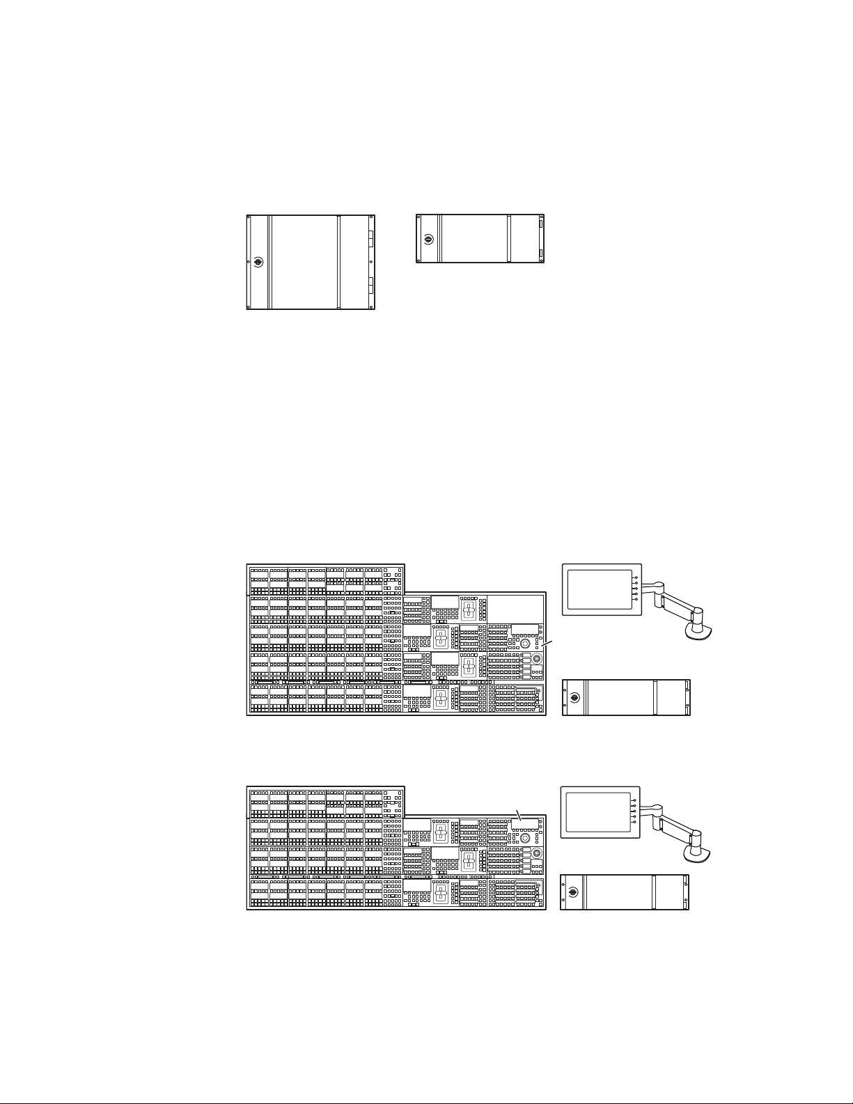
Kayenne Video Processor Frames
The Kayenne Video Processor Frame is available in two sizes. The 8-RU full
size frame supports up to 4.5 ME systems. The 4-RU compact frame sup
ports 1.5-ME through 2.5-ME Kayenne systems (Figure 1). The number of
licensed boards present in the Kayenne frame determines the number of
-
KAYENNE — User Manual 19
Page 20
Section 1 — Introduction
8623266_06
Kayenne 8-RU
Video Processor Frame
Kayenne 4-RU
Video Processor Frame
4-ME 35 Control Panel Menu Panel
Menu Panel
Articulated
Arm
8623266_01
Panel Control Unit (PCU)
Optional Device
Control Module
Optional
Module
Menu Panel
Menu Panel
Articulated
Arm
8623266_02
Panel Control Unit (PCU)
3-ME 35 Control Panel
Optional Device
Control Module
MEs available, as well as the number of video inputs, outputs, GPIOs and
Relay Tallies.
Figure 1. Kayenne Video Processor Frames
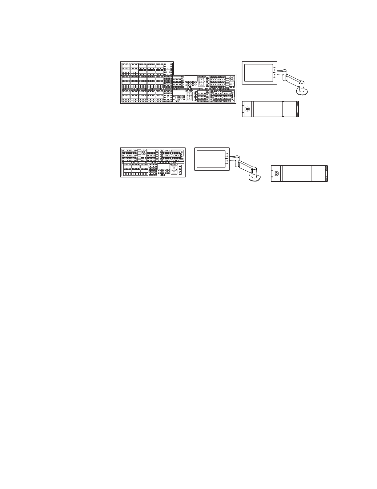
Kayenne Control Surfaces
A Kayenne control surface typically consists of a Control Panel, a Menu
Panel with an included articulated support arm, a Panel Control Unit
(PCU) frame, and optional Satellite Panels. This control surface has an
innovative modular design. Representative Kayenne control surfaces are
shown in the following illustrations.
Figure 2. Kayenne 4-ME 35 Control Surface
Figure 3. Kayenne 3-ME 35 Control Surface
20 KAYENNE — User Manual
Page 21
Kayenne Control Surfaces
Menu Panel
Menu Panel
Articulated
Arm
8623266_04
Panel Control Unit (PCU)
1-ME 15 Control Panel
Figure 4. Kayenne 2-ME 25 Control Surface
2-ME 25 Control Panel
Figure 5. Kayenne 1-ME 15 Control Surface
Menu Panel
Menu Panel
Articulated
Arm
Panel Control Unit (PCU)
8623266_03
The modular design and use of a separate PCU supports the hot-replacement of individual Control Panel components, if necessary, while the rest
of the system remains operational.
Multiple Suites and Control Surfaces
A Kayenne system can be subdivided into two suites, if desired, each of
which can have two control surfaces. Hardware resources in the Video Pro
cessor Frame can be assigned to an individual suite during configuration,
essentially creating two separate switchers from one Kayenne system. A
Kayenne PCU can support two control surfaces using its eight available
ports.
Flat or Curved Control Panel Orientation
The main Kayenne Control Panel supports different physical orientations.
Besides a conventional flat surface, a special support design permits a
curved working surface, where the MEs progressively tilt for improved
ergonomics (
Figure 6).
-
KAYENNE — User Manual 21
Page 22

Section 1 — Introduction
Hold
Hold
A
Hold
BU1U2
Hold
Far
Key
Split
Rules
Hold
EMEM
Sec
Aux
Pri
Key
3
Key
1
Macro
Key
5
Key
4
Key
2
RtrKeKey
6
EMEM
Macroro
Rev
Rwd
Run
Tr
ans
Rate
Auto
Run
Pa
nel
Mem
Menu
Mix
Transns
PVW
Tr
ans
Rate
EMEM
Runun
Ptntn
Limit
Pst
BLK
Key
1
Key
2
Key
3
Key
4
Key
5
Key
6
Key1
Cut
Key2
Cut
Key4
Cut
Key3
Cut
Key6
Cut
Key5
Cut
Key1
Auto
Key2
Auto
Key3
Auto
Key4
Auto
Key6
Auto
Cut
Auto
Key5
Auto
Userer5Userer
6
Userer4W
ipe2W
ipe
1
Userer3Userer2Userer
1
Key
Prior
Control Panel Stripes
Figure 6. Curved and Flat Control Surface Installations
Flat Control Panel AssemblyCurved Control Panel Assembly
8623266_36
The main Kayenne Control Panel is organized into from one to five Stripes.
Each Stripe consists of a tray and its complement of drop-in modules. An
ME Stripe has a module for Source Selection, Transition, and individual
E-MEM control (
Figure 7). Additional Master E-MEM, Machine Control,
Multi-Function, and Local Aux modules are populated to complete the
control surface functionality.
Figure 7. Portion of Control Panel ME Stripe
Key
Key
Hold
Key
Spl
Hold
Hold
Hold
Key
Macro
Far
Key
Key
Rules
Sec
Hold
Key
Key
Key
EMEM
ipe
Cut
Key
ipe
Auto
Source Module (35, 25, or 15) Local E-MEM ModuleTransition Module
Control Panel Modules
The following Kayenne modules are available:
ans
EMEM
Lim
Key
Key
Ke
Ke
Auto
Cut
Ke
Ke
Auto
Cut
Ke
Ke
Auto
Cut
Ke
Ke
Auto
Cut
Ke
Ke
Auto
Cut
Ke
Ke
Auto
Cut
EMEM
ans
nel
Rate
Mem
Me
Ma
Run
Rev
Rwd
Run
8623266_54
• KAYN-PNL-TRM - Transition Module
• KAYN-PNL-LEM - Local E-MEM Module
• KAYN-PNL-MEM - Master E-MEM Module
22 KAYENNE — User Manual
• KAYN-PNL-MFM - Multi-Function Module
Page 23
• KAYN-PNL-SRC-35, 25, 15 - Source Module, available in 35, 25, and 15
button widths.
Note 15 button widths are only available with 1-ME Control Panels.
• KAYN-PNL-AUX-35, 25 - Local Aux Module, available in 35 and 25
button widths.
• KAYN-PNL-BAR-35, 15 - System Bar, available in two sizes to match
various Control Panel widths.
• KAYN-PNL-DCM - Device Control Module, available as an option for
3 and 4-ME panels and as a satellite panel module.
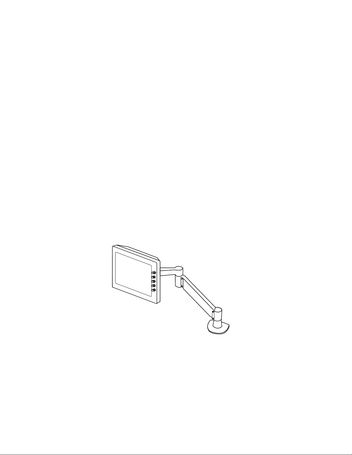
Touch Screen Menu Panel and PC Menu Control
Each Kayenne control surface includes a Menu Panel that features a wide
format 15 in. touch screen display. An articulated arm is also included,
offering a wide variety of installation options (
has a standard VESA-75 hole pattern and M4 threads, compatible with this
and many other mounting devices.
Kayenne Control Surfaces
Figure 8). The Menu Panel
The Menu Panel has four USB ports, two on the right side edge of the panel
and two on the back for keyboard and mouse (wired or wireless are sup
ported).
Figure 8. Menu Panel with Articulated Arm
8623266_05
An additional touch screen Kayenne Menu Panel is available as an option
(additional Menu Controller Board is required in the PCU).
It is also possible to run the Kayenne Menu application on a standard PC,
permitting mouse and keyboard control from a laptop, or remote control
from any location on the network.
-
KAYENNE — User Manual 23
Page 24

Section 1 — Introduction
Panel Control Unit
The Kayenne Control Panel and Menu Panel(s) are powered from a separate rack mount Panel Control Unit (PCU). Control surface processing and
communications are handled by this unit. The PCU eliminates the need for
cooling fans in the Control Panel and Menu Panels, making for quiet
system operation.
Redundant Power Supplies
Optional built-in redundant power supplies are available for the Kayenne
4-RU and 8-RU Frames. An additional redundant power supply is stan
dard with the Kayenne PCU.
Supported Control Protocols
-
All Kayenne systems support the following control interfaces and types of
external devices:
• Serial control of VTR/DDR (BVW, AMP, and Odetics protocols),
• Ethernet control of DDR channels (AMP protocol),
• Peripheral Bus II protocol,
• Tally (Contact Closure and Serial),
• GPI Inputs and Outputs,
• Routing Control Systems (Jupiter, Encore, SMS-7000, and third party
routers), and
• Grass Valley Editor protocol.
24 KAYENNE — User Manual
Page 25

Concepts
Introduction
Section 2
In general, any video switcher receives multiple video inputs, performs
signal processing on selected input signals, and then outputs the processed
video. Efficient real time switcher operation is essential for live production,
and can save valuable time in post production environments as well.
Several innovative concepts are employed in the Kayenne Video Produc
tion Center to enhance its operational speed and flexibility. Understanding
these concepts, as well as basic switcher fundamentals, will help you take
full advantage of the exceptional power of the Kayenne system.
-
Kayenne System Configuration Overview
The Kayenne Video Production Center is designed for operational flexibility, and can be configured to fit various applications. Different Kayenne
systems can have different capabilities, or the same Kayenne system can be
re-configured to have different capabilities at different times. The system
has also been designed to support multiple users on the same system, but
remains suitable for use by a single operator. For these reasons, it is impor
tant for you to have a basic understanding of how a Kayenne system is configured.
The way a Kayenne Video Production Center is wired into your facility
affects the Kayenne system’s capabilities. For example, the number and
types of sources physically connected to the system obviously determines
what video the system can handle. However, because Kayenne system
inputs and outputs can be configured, once video cables are physically con
nected they need not be moved. Configuration settings also control many
other capabilities that affect Kayenne system behavior.
-
-
KAYENNE — User Manual25
Page 26

Section 2 — Concepts
Engineering Setups
Kayenne Video Production Center configuration information is divided
into three areas, to simplify and increase the speed of reconfiguring the
system. The basic areas of Kayenne configuration are:
• Engineering Setups (settings established by the engineer in charge that
affect the entire system, which never need to be changed by operators),
• Suite Preferences (settings for a suite that affect all the operators
working in that suite, that are designed to suit a particular show or production style and ensure a consistent working environment), and
• Preferences (settings that give the operator the ability to customize his
individual work surface to meet his personal preferences).
All Kayenne configuration settings are non-volatile. Disk save and load
operations are available that allow users to store configuration information
on removable media for easy transport and for use as backup copies.
Engineering Setups control how the Kayenne Video Production Center’s
major components behave and interact, and how the Kayenne system inter
acts with the rest of the facility. Engineering Setups are not likely to change
on a daily basis and so are grouped separately from the Suite and Panel
Preferences. Facility maintenance personnel or the engineer in charge of a
production truck generally manages Engineering Setups.
Note It is not recommended that you store Engineering Setup files with Show files.
Engineering Setups information includes:
• Acquired Resources menu (if assigning ME 50 (half ME) to a logical
ME)
• Networking IP addresses,
• Source definition (described later in this section),
• Output assignment (identifying which output connectors are Program,
which are Preview, etc.),
• External device interfaces (DDRs, VTRs, DPM, Router, etc.),
• Control surface and suite definitions,
• Single Suite or (for Resource Sharing) Multi Suite operating mode, and
-
• Various other system functions.
Suite Preferences
A Kayenne suite corresponds to a control room, where there is a grouping
of one or more control surfaces. Suite Preferences define how all the control
26 KAYENNE — User Manual
Page 27

Kayenne System Configuration Overview
surfaces associated with a Kayenne suite behave when they control the
Kayenne system. Some parameters (for example, safe title displays) must
be identical to all Kayenne users involved in a session. Suite Preferences
can substantially change system behavior, not just a user’s view of the
system. Suite Preferences are intended for day-to-day or session-to-session
changes in Kayenne system operating behavior and so are open for modi
fication by operators.
The Resource Sharing feature makes it possible to configure the Kayenne
system with two suites, corresponding to two different work envrion
ments. Each suite can be operated with its own Suite Preferences settings.
Suite Preferences include:
• Resource Allocation
• Source patching
• Safe title, preview behavior, etc.,
• Default Source Memory (initial keying and video processing settings
used for each source on each bus),
-
-
• Default Keyframe (initial settings for many other user controls), and
• Various other suite preferences.
Panel Preferences
Panel Preferences allow users to customize a Kayenne control surface to
suit their personal operational style. Panel Preferences apply to only one
control surface, and only affect the behavior of the panel controls available
to a single operator. Panel Preferences do not change Kayenne system capa
bilities.
The Resource Sharing feature makes it possible to configure each of the two
two suites with two different control surfaces. Each control surface can run
its own Panel Preferences settings.
Panel Preferences include:
• Source to button mapping (described later in this section),
• Aux bus delegation button mapping,
• Panel color scheme,
•Source color,
-
• Macro and E-MEM start number, and
•DPOP prefs.
KAYENNE — User Manual27
Page 28

Section 2 — Concepts
Signal Routing
Inputs and Sources
Incoming video signals are connected to the Kayenne system via connectors on input modules located at the back of the Kayenne Video Processor
frame. All inputs are serial digital (SMPTE 259M, CCIR 601). Signals from
external devices not operating in this standard will need to be converted.
Some devices (for example, a camera providing serial digital output) may
provide a video signal that can be received on a single connector. However,
other devices may output multiple signals. For example, a character gener
ator usually provides a signal with two components (commonly called
video and key). Some incoming signals may also originate from devices the
Kayenne system can control (Router, DPM, DDR).
Note Although the character generator utilizes two inputs, it should
be defined as only a single Video/Key source (CGx). It is not
required to source define or button map the character generator’s Key signal.
-
For a Kayenne Video Production Center, the term source refers to all the
video signals and other attributes associated with a device. This is a funda
mental concept. The Kayenne system is based on sources, not input signals
or crosspoints. Each source can be given a descriptive name, but has an ID
number for absolute identification. The Kayenne system uses ID numbers,
not source names or input connectors, to identify each source. Defining
each source is an important aspect of the Kayenne system.
Source Definition
When the Kayenne system is first configured, all sources are defined so the
incoming signals from each device can be used effectively. This is usually
done by engineering personnel, not operators, and once set these defini
tions are not changed. A source definition data file tells the system how
many signals a source has (video only, or video and key), which physical
inputs to route whenever a particular source is selected, the default pro
cessing of the source’s key signal (if present), and what external devices (if
any) are associated with that source. Tally is another important attribute of
a source. On-air tally relays are related to sources, not physical inputs or
source select buttons. The source definition process includes assigning a
name to each source. Once sources are defined, they are mapped to specific
source selection buttons. The user is then able to select the source by
pressing its button, and the Kayenne system automatically manages all the
necessary signals, performs any default processing, and enables any addi
tional control capabilities associated with that source.
-
-
-
-
28 KAYENNE — User Manual
Page 29

Source definition data is stored as a part of Engineering Setups. Only one
set of source definition data can be active on a Kayenne system at a time.
Note that source definition is separate from source memory (part of Suite
Prefs), and specifies what processing is to be applied to the source and can
dynamically change during system operation.
Source to Button Mapping
Source to button mapping makes it possible to organize sources on
Kayenne Control Panels in a preferred order. For example, cameras can be
placed on the left side or the right side of the button row, whichever is pre
ferred. Source mapping is distinct from source definition, as source
mapping only involves the location of sources on the Control Panel and
does not affect any capabilities defined for the sources. Note that E-MEM
effects store the source IDs, not the source select buttons, so remapping or
unmapping of sources will not change the appearance of recalled effects.
On the Kayenne system, button mapping for each Control Panel bank and
Local Aux Module can be different.
Signal Routing
-
Source Naming
Names can be given to sources. The Kayenne system actually supports different source naming schemes, with associated IDs, to accommodate different needs.
Engineering ID – An unchanging numeric value associated with a source. This
value is used to unambiguously identify each source from an engineering
perspective, regardless of how it may have been named. On-air tally uses
Engineering IDs so the proper device always receives tally.
Engineering Name – An editable name that can be associated with a source,
intended for use by facility engineers to ease source identification. An Engi
neering name may that of a particular hard wired device (Cam 1), or it may
indicate a patch bay location or a router source or destination. Naming
sources in this manner can help engineers configure and re-configure their
facility wiring.
Logical ID – An unchanging numeric value associated with a source used in
a production environment. E-MEMs, source selection, macros, source
memory, and source rules, all use Logical IDs.
Alternative Names – Alternative editable names that can also be associated
with a Logical ID. Generally alternative names are short to make larger
characters appear in the Kayenne system Displays.
-
Source Patching
The Kayenne system allows logical sources to be associated with different
engineering sources. A source patch table is used to map Logical IDs to
Engineering IDs. This table acts like a patch bay. It then becomes possible
KAYENNE — User Manual29
Page 30
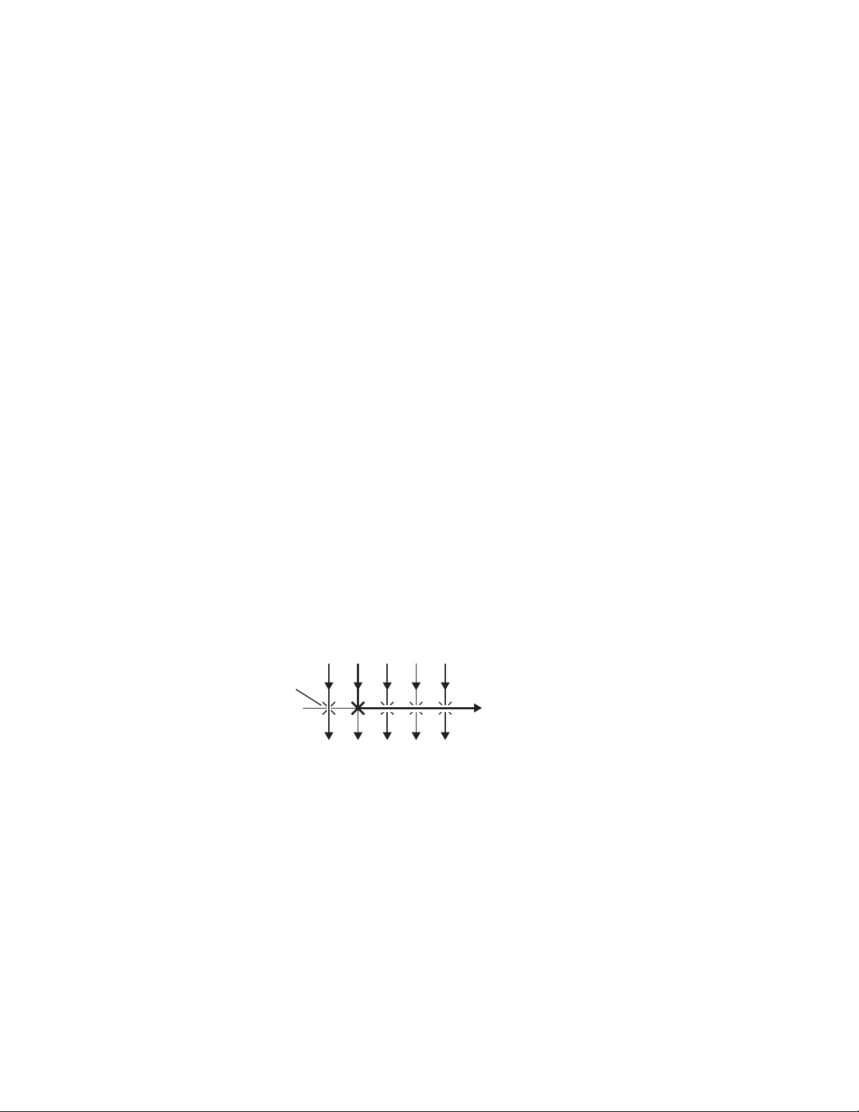
Section 2 — Concepts
Source Memory
Buses and Crosspoints
to use effects in different environments. For example, effects created in one
production truck equipped with one set of devices can be used in a dif
-
ferent truck with different devices by modifying the source patch table.
Source Patching associates all attributes of a defined source’s tally and attributes if included, for example: key signal, external device settings, and
router destination settings.
Keying and other parameters can be saved to a separate source memory for
every Kayenne system source. These parameters can be applied automati
cally whenever that source is selected. See Source Memory on page 65 for
specific information.
A bus is technically defined as a signal path where one of several available
inputs can be selected to feed a single output. A crosspoint is an electronic
switch that allows a signal to pass when the switch is closed. On video
switchers, a bus can be constructed containing a series of crosspoints,
which permits selecting which one of several incoming signals will be sent
out the bus. In
Figure 9, source 2 has been selected on the background A
bus. This signal can now be called background video and is available for
further processing.
-
Figure 9. Buses with Crosspoints
Source Signal Inputs
12345
Crosspoint
Switch
Background A Bus
Signals Continue to Other Buses
061_00_20
Buttons on a Control Panel can be used to control the switching of crosspoints. The buttons are usually arranged horizontally, making it easy to
imagine the available signals coming in from the top, and the single bus
output signal going out the right side.
In earlier generation switchers, the terms crosspoint button and crosspoint bus
have been used in reference to Control Panel source selection. For a
Kayenne system, the terms source button and source bus will be used. These
terms better reflect a system operating philosophy that is based on sources
rather than crosspoints. The Kayenne system does not directly associate a
source select button with a physical crosspoint. The association goes first
30 KAYENNE — User Manual
Page 31

Signal Routing
through source to button mapping, then through source definition to find
the physical inputs.
On the Kayenne system, a single source button can control crosspoints on
different buses simultaneously. For example, during keying on an ME, both
the video and key signals of a source can be selected with a single button
press. In this case two different crosspoints on separate buses (key fill bus
and key cut bus) are actually switched when the button is pressed. In the
upper part of
Figure 10, the video component of source 2 in the figure has
been selected on the key fill bus and becomes the key fill signal for subsequent keying. The key component of source 2 selected on the key cut bus
becomes the key cut signal for keying. The lower part of
Figure 10 shows
how the same source (source 4) can be selected for both the key fill and key
cut signals.
Figure 10. Multiple Crosspoint Control
Source Signal Inputs
123 45
Key
Key Video Key Video Video Only Video OnlyVideo
1 3 4 5
Single Button Controls Both Crosspoints
1 3 4 5
2
2
Single Button Sends Same Signal to Both Buses
Shifted Sources and Shift Preference
There are four levels of shift with Kayenne. See Source Button Mapping on
page 126 for more information.
Key 1 Fill Bus
Key 1 Cut Bus
Key 2 Fill Bus
Key 2 Cut Bus
0618_00_21_r1
Mix/Effects (ME)
An ME is a subsystem of a video production switcher that can create a composite of two or more pictures. An ME includes multiple source selection
KAYENNE — User Manual31
Page 32

Section 2 — Concepts
Source Signal Inputs
Crosspoint
Matrix
Keyer
Mixer
Wipe
Generator
M/E
Outputs
Background A
M/E Program
M/E Preview
Background B
Key Cut
Key Fill
buses and provides transition (mix and wipe) and keying capabilities on
the selected signals.
A simple basic ME used in a typical switcher will be used as an example in
the following discussion. A Kayenne ME has added capabilities, but the
basic principles described here will apply. See Section 1 - System Overview
for a simplified diagram of the actual Kayenne ME architecture.
Figure 11. Simplified Mix Effects (ME) Subsystem
The basic ME shown in Figure 11 has an A and a B background bus. These
buses select the background video signals sent to the output of the ME.
Generally the source on the background A bus is the current background
output, and the source on the background B bus is the background video
that will be used next. During most transitions, portions of both back
grounds are output simultaneously. The keyers in the ME allow the inclusion of additional material over the background. Wipe generators also
exist, which create patterns used by the mixer for wipe transitions, or used
by the keyers to modify the signals it sends the mixer. See
Transitions on
page 35 and Keying on page 39 for more information. The processed signal
in an ME is then sent to an ME output, typically program or preview.
32 KAYENNE — User Manual
Each Kayenne ME actually is able to produce up to six outputs (Program A,
Preview A, Program B, C, D, and Preview 2 that is shared by the three addi
tional program outputs). These additional outputs allow great flexibility in
configuring a Kayenne system for special purposes.
Logical Assignments of MEs
A video production switcher can have more than one ME. For example a
4.5-ME Kayenne system has five (ME 1, ME 2, ME 3, ME 4 and PGM
A 4.5-ME frame consists of four full ME cards, A, B, C, and D and the stan
dard Half ME (ME 50). Any frame ME can be assigned to the logical MEs
by using the Eng Setup, Acquire Resources menu. ME 50 could be assigned
as ME 2 or later assigned as PGM/PST on a show-by-show basis. Any of
the frame’s MEs can be assigned to one of the five logical Kayenne MEs.
-
PST).
-
Page 33

Re-Entry
Utility Buses
Signal Routing
Switchers with multiple MEs generally have re-entry capabilities. Re-entry
permits the switcher to select the output of one ME for use as an input
source to another ME. The signals are routed internally.
The Kayenne system supports ME re-entry in any order. For example, an
output of ME 2 can be sent to ME 1, and an output of ME 1 can be sent to
ME 3. Infinite looping re-entry (for example, ME 1 sent to ME 2 and ME 2
sent back to ME 1) is allowed but should be done with great caution.
Besides the standard A and B background buses, each Kayenne ME also
accepts Utility 1 and Utility 2 inputs. Kayenne Utility buses can be used to
select signals for special purposes, and have no relation to the background
buses. For example, a video signal selected on a Utility bus can be used to
fill a keyed Borderline border, to feed a custom pattern into a wipe gener
ator, or create a custom border wash pattern. When the ME is in DoubleTake, Split ME mode, the Utility Buses contribute to the secondary mixer of
that ME allowing for independent ME transitions
-
Outputs
Output Mapping
Video production switchers generate several different video outputs (Program, Preview, etc.). A final program output from PGM PST is typically
sent to the Master Control/Transmission for broadcast and/or to servers or
VTRs for recording. Individual ME program and preview outputs and an
additional switched preview output are sent to monitors in the control
room. These outputs may also be routed elsewhere in the facility. Aux Bus
outputs may also be used for studio display systems, ISO feeds, and
complex clean feeds.
Unlike earlier generation switchers, all the Kayenne system outputs are
configurable. There are no dedicated output connectors. Any signal can be
assigned to any output connector, which provides flexibility and control of
the number of fixed and up to 46 Aux bus outputs the system will have. A
fixed output is always the same, while an Aux bus’s output can change
depending on what source has been selected on that bus. Once the fixed
system outputs have been assigned, all the remaining outputs can be
assigned for use with Aux Buses. When the system is configured, the out
going signals are assigned to connectors on output modules located at the
back of the Kayenne Video Processor.
-
KAYENNE — User Manual33
Page 34

Section 2 — Concepts
Aux Buses
The most important difference between a fixed output and aux bus is that
an operator has control over an aux bus but a fixed output always provides
the same signal. Aux bus outputs also support YUV color correction and
optionally RGB color correction with E-MEM and macro control. If an
output is assigned to a fixed output, any color correction settings are
bypassed and the output is set back to unity default.
Video production switcher Aux Buses can be used to select and route
sources to specific destinations. For example, a source selected on an Aux
Bus can be sent to an ISO recorder for instant replay. This can be done
directly by the Technical Director while he switches the program. Remote
Aux Panels can be used to give different operators control over one or more
Aux Buses.
On the Kayenne system, each Remote Aux Bus panel can have its own
source to button mapping. Source name displays on the 2 RU Local Aux
Module show what source is currently available for each button. Aux Buses
can also be configured in pairs, to send matching key cut and key fill signals
to external devices, Remote Aux Panel IP Address, Logical Aux settings,
and Button Mapping are exclusively saved with the Eng Setup file.
Point Of Use
The Kayenne system can share some resources for use at different locations.
The location where a resource is being used is called a point of use. Different
types of resources are shared differently.
Floating resources (like Transform Engines) move between points of use,
and the parameters controlling these resources are considered part of the
point of use. These resources are used at only one point of use at a time.
When the resource floats to the new location, its behavior changes. For
example, a Transform Engine can be set for 0.25 Z rotation (parameter) on
ME 1 Key 2 (point of use). That same Transform Engine can then be
assigned to ME 2 Key 3 and set to a Z rotation of 0.0. When the Transform
Engine is reassigned back to ME 1 Key 2, the 0.25 Z rotation parameter will
be restored.
Other Kayenne system resources behave differently. For example, wipe
pattern generator resources can be used for an ME wipe transition, as a
preset pattern, as a mask, or at other points of use. It is also possible to
assign the output of the same wipe pattern generator to different points of
use at the same time. For efficient operation, the Kayenne system has
divided the parameters controlling wipe pattern generators and related
utility bus functions into two categories; shared generator parameters and
point of use parameters. The set of parameters for the shared generator are
used by all points of use, so changing one of these parameters will affect all
34 KAYENNE — User Manual
Page 35

Transitions
locations where that wipe pattern generator is being used at that time. Separate sets of point of use parameters, however, are maintained for each
Kayenne system point of use (same as Transform Engines described above).
These settings are used only by each individual point of use, so changing
them will not affect any other point of use. For example, a wipe shape (box,
circle, etc.) is a generator parameter, but the softness of the shape’s edges is
a point of use parameter. If the same wipe generator is used by both an
ME wipe transition and a preset pattern, adjusting softness at one point of
use will not affect the other’s softness settings. However, changing the
pattern shape affects both locations.
Kayenne systems differ from the Grass Valley Model 4000 switchers in the
division between wipe pattern generator and point of use. In the 4000, the
edge is created as part of the generator so all points of use have the same
softness and border width. The Kayenne system duplicates this circuitry
allowing each point of use to have a different edge on the same basic wipe
pattern shape.
Transitions
A transition is a change from one image to another. The Kayenne system
supports three basic types of transitions:
•Cut
•Mix
•Wipe
A transition can be applied to the entire picture, or to only the background
or keyed elements of the picture, and can include multiple elements. See
Current and Next Stack on page 38 for information on transitions involving
more than one element.
Cut
A cut is an instantaneous switch from one image to another (between successive video fields or frames). The simplest type is a hot cut, accomplished
by selecting a different source on a bus feeding an ME output. This only
changes that bus’s contribution to the output, and does not change what
elements may be involved in the output (the same buses are involved).
The Kayenne system also provides cut transitions, where the elements
involved in a composite can be changed instantaneously. Different buses
can be included or excluded, causing changes in the resulting composite
image. Background cut transitions on an ME are first selected on the Back
ground B bus to allow previewing the upcoming picture before it is cut onair.
KAYENNE — User Manual35
-
Page 36

Section 2 — Concepts
Crossfade
Transition
Start End
Midpoint
Current
Picture
Picture
Intensity
Next
Picture
Current
Picture
Next
Picture
NAM, FAM
Transition
Start End
Midpoint
Mix
Mix Through Video
Non-Additive Mix, Full Additive Mix
A mix is a transition from one picture to another where the new picture
fades in as the existing picture fades out. During a standard mix transition
a superimposition of both pictures, each at a lower intensity, is visible.
The Kayenne system allows mixing from one background to another and
to mix up to six separate keys on or off over a background. Background and
key mixes can be done separately or simultaneously.
A Mix Through Video transition is a special mix transition that incorporates a third intermediate video source. This type of transition can mix from
one video source, through a matte or Utility bus video source, to the final
video source, all as one transition.
Non Additive Mix (NAM) and Full Additive Mix (FAM) are special mix
transitions that the Kayenne system supports besides normal crossfade
transitions. Picture elements in NAM and FAM transitions are composited
differently through the time of the transition(
Figure 12).
Figure 12. Normal, NAM and FAM Mixes
NAM transitions pass only the brightest regions of each picture to the
output. During the first half of a NAM transition the original picture retains
its original intensity while the next picture mixes to full intensity. Brighter
areas in the new picture replace any corresponding darker areas of the pre
vious picture. During the second half of a NAM transition the previous
picture mixes out of the darker areas of the new picture. FAM transitions
also first fade a new picture to full intensity and then fade the old picture
out, but both full intensity pictures are mixed together to the output during
the transition. The resulting signal is clipped at white level to prevent gen
erating illegal video.
-
-
36 KAYENNE — User Manual
Page 37

Wipe
A wipe is a transition from one picture to another in which the edge of a
shape moves across the screen, revealing the new picture. Wipe transitions
can be applied to backgrounds, to keys, or to both simultaneously. A wipe
transition shape can be selected from a variety of patterns, and these pat
terns can be adjusted in several ways (position, aspect ratios, edge attributes, etc.).
Each Kayenne ME has two separate wipe systems, each of which can be
assigned a different wipe pattern and be adjusted independently. These
systems can each use one of the two available complex wipe pattern gener
ators with advanced capabilities. It is also possible to combine these wipes
to create extremely complicated wipe transition shapes, and generally this
is used only by advanced operators. Utility bus video signals can also be
used to generate a custom pattern for a wipe transition or other purposes.
Other Wipe Pattern Generator Uses
Wipe pattern generator circuitry can be used for purposes that do not
involve transitions. Each Kayenne ME has the two complex wipe pattern
generators described above, and each of its six Keyers also has a simple
pattern generator and a box pattern generator, making a total of six. These
pattern generators can also be used for Preset Pattern, Masking, and Matte
Was he s.
Transitions
-
-
Preset Black
Preset Black is a special type of transition, where the picture transitions to
black, and then transitions out of black to the new picture. Preset Black is
really two transitions, one to and one from black, and so requires two oper
ator commands to complete. Preset Black can be used with any transition
type (cut, mix, or wipe). The entire picture goes to black, even if all the tran
sition elements involved in the picture were not selected.
Transition Rate
Cut transitions are instantaneous, but mix and wipe transitions have durations. Transition durations can be set in advance to a specific transition rate,
and be initiated by pressing a button the Control Panel. It is also possible to
manually control transitions using a lever arm.
On the Kayenne system, one transition rate can be assigned to the main
transition of each ME. This type of transition can be controlled by that ME’s
lever arm. Each of the six keyers on each ME can also be assigned its own
transition rate, initiated with a separate Key Mix button on that ME.
-
-
KAYENNE — User Manual37
Page 38

Section 2 — Concepts
Flip Flop Background Buses
Look Ahead Preview
At the completion of a transition, the background buses swap their source
selections (flip flop). This makes the upper bus always act as the on-air bus,
and the lower bus act as a preset bus. The operator can reliably setup the
next source on the lower bus without disturbing the source selected on the
on-air upper bus.
For example, if a transition begins with source 1 on Background A and goes
to source 2 on Background B, as soon at the transition to source 2 completes,
source 2 will be taken to the Background A bus (without disturbing the
output of that ME). The source 1 selection will also be immediately taken to
the Background B bus.
If a preview monitor is configured for Look Ahead Preview mode, the end
result of the upcoming transition can be viewed on that monitor. This lets
the operator know in advance what will occur for that next transition. The
mode you select for each preview monitor depends on the number of mon
itors available and the individual requirements of the facility.
-
Current and Next Stack
Kayenne uses a current and next stack approach for transitions that involve
multiple elements. The current stack is the current ME output including
any keys that are on. The next stack is defined by the current stack and
whatever next transition elements have been selected. Look ahead preview
always displays the next stack. Next transition elements affecting stacks are
Keys 1 - 4, background, and key priority.
Kayenne transitions always occur from the current stack to the next stack.
For example, if the current stack has Key 1 over Background A, and the next
stack specifies Key 2 over Background B, a mix transition will occur
between the composites (Key 1 over A to Key 2 over B). This is different
from mixing Key 1 off, Key 2 on, and mixing between A and B at the same
time, which would cause the keys to go transparent over their background
during the transition. On the Kayenne system, opacity is retained
throughout the transition, so midway through this example Key 1 remains
fully keyed over Background A, and Key 2 is fully keyed over Background
B. The transition occurs between these two fully keyed composites.
Key Priority and Transitions
The six keyers on a Kayenne ME can be assigned priorities. This determines
the layering of the keys. The highest priority key appears on top, while
38 KAYENNE — User Manual
Page 39

Keying
Keying
keyers with lower priority may be partially or fully hidden behind those
with higher key priorities. The backgrounds always have the lowest pri
ority. Changes in key priority can be included as a part of a transition. Like
any other transition, the current stack will transition to the key priority of
the next stack. For example, suppose the current stack has Keys 1, 2, and 3
in that key priority order over Background A, and the next stack specifies
key priority order 3, 2, 1. A mix transition will occur between the 1, 2, 3
composite order to the 3, 2, 1 composite order. All three keys will remain
fully keyed over the background, and will mix to their new key priority
order.
Keying inserts part of one picture into another to create a composite picture. Keying involves three signals:
• background,
• key cut, used to specify where to cut a hole in the background, and
-
• key fill, used to fill the hole in the background. The fill can be an
incoming video signal or it can be an internally generated matte.
A separate key cut input signal is not necessarily required for keying. For
example, a self key (also called a video key) uses the same input signal for
both key cut and key fill.
The Kayenne system supports the following types of keys:
• Linear Key (fixed and adjustable)
• Luminance Key
• Preset Pattern
• Chroma Key (option)
The Kayenne system also supports self keys and split keys.
Matte Fill Key Example
One of the earliest keying techniques was to use an art card and camera to
perform a luminance key with a matte fill. This type of key is a good
example for explaining basic keying principles because three separate and
independent incoming signals are used.
To insert a green logo into background video, the logo can be printed in
white on black paper and a camera can be focused on it. The signal from the
camera can be selected as the key cut signal and green matte video can be
selected as the key fill signal sent to the keyer. The key cut signal is then
adjusted (clipped) to ignore the black paper and use only the white logo
KAYENNE — User Manual39
Page 40

Section 2 — Concepts
LOGO
LOGO
shape to cut a hole in the background video. The keyer then shapes the key
fill to precisely match the logo-shaped hole cut in the background and fills
it with green matte video. This creates a green logo inserted into the back
ground (Figure 13). Because luminance values of the key cut signal are
used to cut the hole in the background this is called a luminance key.
Figure 13. Matte Fill Luminance Keying Example
Background
-
Shaping Video
LOGO
Key Cut
Key Fill
In this keying discussion illustrations rather than actual screen images are
used for simplicity, and because the printing process has difficulty cap
turing the subtleties of soft key edges.
In the matte key example above, the key fill signal was a full raster color
that did not match the shape of the key cut signal. This key fill signal is
accurately called non-shaped video, but may also be referred to as unshaped
video since both signal types are processed identically during keying.
LOGO
Background with Matte Key Inserted
0618_00_32_r1
-
Some external devices (e.g., character generators) provide a key cut signal
and an already processed companion key fill signal. A key fill signal that
correctly matches the key cut signal is called shaped video. During keying,
properly shaped key fill video can be summed with a background signal
(with a hole cut) and achieve the desired result. When the shaping is per
formed by the source device, the Kayenne system can use a standard clip
40 KAYENNE — User Manual
and gain setting defined during system configuration to create the key cut
control signal, and so relieve the operator of having to adjust clip and gain
manually.
-
Page 41

Keying
If a key fill does not match the hole in the background (like in the matte key
example above), the key fill needs to be shaped by the switcher. By multi
plying the key fill signal with the key control signal the unwanted areas of
the fill can be made black, shaping the video to match the hole before it is
summed with the background. Key fill video must be shaped using the key
cut signal actually used to create the hole in the background. Video shaped
with a different key cut signal will not key correctly.
The Kayenne system, as well as some external devices like DPMs, can also
divide a shaped video signal by its own key signal. The result is called
unshaped video. For optimum image quality, shaping and unshaping oper
ations should be minimized. In general, devices should be installed and
configured in a manner that prevents them from having to unshape
incoming video just to reshape it again afterwards.
Specifying whether source signals are shaped or unshaped is part of the
Kayenne system configuration process (source definition). Properly shaped
video is an important aspect of keying. See
Video on page 51 for more information.
Note that an unshaped signal viewed directly will show harsh edge artifacts due to dividing by a small number. This is normal and expected.
Keying this signal will clean up its appearance.
Properly and Improperly Shaped
-
-
Key Control Signal Adjustment
During keying, the selected key cut signal can be converted into a key
control signal. It is the key control signal that actually cuts the hole in the
background video. Adjusting the key control signal (Clip and Gain) is
essential in the keying process. The art of setting up a good key is to use just
enough Gain to suppress any imperfections in the incoming key signals.
Setting Gain too high can cause ragged key edges.
The Kayenne system provides two methods for adjusting the key control
signal, Clip and Gain, and Clip Hi and Clip Lo. Note that the same basic
keying process is controlled by either of these methods.
Clip and Gain
The Clip and Gain operation selects a threshold of the selected key cut
video that will be used to cut the hole in the background video. Clip con
trols the threshold, and Gain controls the softness of the key edges and any
translucent areas. High portions of the key cut signal specifies what video
is retained, and low portions determine what video is removed. Interme
diate levels specify a soft blend of the background and fill video
Figure 14).
(
-
-
KAYENNE — User Manual41
Page 42

Section 2 — Concepts
0618_00_31_r1
Key Cut
Signal
Key Control
Signal
Key Control
Signal
Inverted
(Hole Cutter)
Video
Retained
Mix of
Background
and Fill Video
Video
Removed
Background Video
Removd
Background Video
Retained
Clip
Gain
Figure 14. Key Clip, Gain, and Key Control Signal
Clip and Gain control is appropriate for high gain keys (see below), to
easily adjust where the relatively hard transition from background to fill
occurs. In this mode, changing the Clip control moves the threshold up and
down without affecting Gain, which is adjusted separately with its own
Gain control.
High Gain, Low Gain, and Unity Gain
A high gain key has a narrow range, creating harder key edges. A low gain
key has a wider range, creating softer key edges. Linear keys typically use
minimal gain (also called unity gain) to completely preserve the soft edges
of the keys (
that go below unity gain.
Figure 15. Keying Gain Values
Gain
Clip
High Gain Low Gain
On the Kayenne system, Gain has a percentage value. A Gain value of 50%
requires a luminance change of 50% of the distance between black and
white to produce a keying signal ranging from transparent to opaque. A
gain value of 100% (unity gain) uses the entire range between black and
white for this transparent to opaque transition. A gain value of 0% pro
duces the hard key edges (a high gain key).
42 KAYENNE — User Manual
Figure 15). Note that the Kayenne system also supports keys
Gain
Gain
Clip
Clip
Unity Gain
-
0618_00_30_r1
Page 43

Clip Hi and Clip Lo
Key Cut
Signal
Clip
Gain
0618_00_29
Clip Hi
Clip Lo
The Kayenne system also supports a Clip Hi and Clip Lo mechanism. With
Clip Hi and Clip Lo, two thresholds are established. The upper threshold
specifies at what point video will be completely removed from the back
ground, and the lower threshold determines at what point background
video will be retained completely intact (
Figure 16. Key Hi, Clip Lo vs. Clip and Gain
In this mode, Gain changes when either control is adjusted. The difference
between the upper and lower keying thresholds is equivalent to gain:
Keying
-
Figure 16).
Clip Hi = Clip + Gain/2
Clip Lo = Clip – Gain/2
Clip Hi and Lo control is more appropriate for low gain keys, to allow independent control of the two thresholds. For example, when adjusting a
linear key the operator wants to control where the fill becomes opaque
(Clip Hi) and where the fill becomes transparent (Clip Low). In Clip Hi/Lo
mode adjusting the point of opacity does not change the point of transpar
ency, and vice versa.
Clip, Gain, Clip Hi and Clip Low adjustments always interact. Changing
one always results in changes to two other values. Changing Clip Hi or Clip
Low changes both Clip and Gain, not just Gain.
S-Shaped Key Signals
On the Kayenne system, an S-shaping function is applied to the edges of
luminance keys. S-shaping smooths the sharp corners of a luminance key
control signal, which helps prevent banding artifacts. S-shaping a signal
minimally affects the key edges, and does not move key thresholds or affect
the overall gain of the key (
-
Figure 17).
KAYENNE — User Manual43
Page 44

Section 2 — Concepts
Figure 17. S-Shaped Luminance Key Control Signal
Key Control Signal
S-shaping is generally not applied to linear keys because the external
device usually applies an S-shaping function when it generates the key cut
and key fill signals. S-shaping should not be applied twice.
Additional Keying Controls
The following additional controls are available for keying.
Key Invert
Keys can be inverted, causing holes to be cut in the background where a
normal key retains the background, and vice versa. Key invert makes the
white areas of the key cut signal produce transparency, and the black areas
produce opacity, the opposite of a standard key.
Borderline
The Borderline feature generates borders around keys. The key signal is
delayed and/or enlarged, and the extra bordering space can be filled with
matte or video. Borderline can be adjusted in size, and in horizontal and
vertical placement.Variations on Borderline include Shadow, Extrude, and
Outline.
S-Shaped
Key Control Signal
0618_00_33_r1
Masking
Masking defines areas that are protected from keying (Inhibit Mask) or
always key (Force Mask). The shape of the mask can originate from a wipe
pattern generator or by a selected mask signal (typically a key fill signal
delivered via one of the Utility buses).
With the Kayenne SuperStore option, the mask signal can be a frozen page
of video or a key fill. Complex mask shapes are often easier to draw by
hand than to create with multiple wipe patterns. The Kayenne system sup
ports drawing masks into a SuperStore page using a third party graphics
tablet.
44 KAYENNE — User Manual
-
Page 45

Opacity
The opacity of a key can be adjusted. When opacity is reduced below 100%
some background video is allowed to show through areas where it is nor
mally excluded. Key opacity is an adjustment to the overall intensity of the
key, and is separate from Clip and Gain controls. Note that a common
mistake is to set opacity to zero and forget that adjustment was made,
which can cause confusion later when that key is selected but not visible.
Key Positioning
Key positioning allows slight adjustment of the horizontal position of the
key cut signal relative to the key fill signal. This is useful if the timing of the
two signals at the switcher inputs are not matched properly. This is gener
ally only a problem if the cut or fill follow analog paths from source to
switcher or if the source has video/key timing adjustments which have
been set to compensate for other delays within the facility.
Key Size
Keying
-
-
Key size allows the key cut signal to be narrowed slightly. This can greatly
enhance self keys and chroma keys that have been reshaped.
Coring
Coring helps reduce video noise in Chroma keys. Coring is used when a
key fill signal has noise in areas that are supposed to be transparent. When
noise exists in these areas it can appear in the background portion of the
keyed composite. Coring replaces the noisy black areas outside the shaped
fill with clean black before it is summed, eliminating the noise.
Show Key
Although the key control signal is not directly visible in the final video
output, this signal can be previewed as a black and white image using the
Show Key function. White areas of a show key indicate areas of complete
opacity, black indicate complete transparency, and gray areas indicate
translucent areas of the key. The whiter the show key signal, the more
opaque the key will be. This key preview signal reflects all the adjustments
that have been made to the key control signal.
Linear Key
A linear key typically uses separate key cut and key fill input signals that
are intended to be used for linear keying. The key cut and key fill are
usually anti-aliased (soft edged) shaped signals created by a character gen
erator or graphics system. There may also be translucent areas intended to
KAYENNE — User Manual45
-
Page 46

Section 2 — Concepts
LOGO
LOGO
LOGO
LOGO
LOGO
allow some background to show through the key (watermarks). The level
of the key cut signal determines where and how deeply the hole will be cut
into the background. The intended soft edge and translucency of the key
can then be faithfully reproduced (
Figure 18. Linear Keying
Figure 18).
LOGO
Background Video
LOGO
Key Cut Key Control
Clip
Gain
Key Fill
Note The soft edges in the illustrations in this part of the manual are simulated. The
LOGO
(typically unchanged)
key edges are actually gradients, which allows these edges to blend smoothly
with the background.
Key Hole in Background
x
Invert
+
Completed
Linear Key
0618_00_61
46 KAYENNE — User Manual
Fixed and Adjustable Linear Keys
The Kayenne system supports both fixed and adjustable linear keys. A
fixed linear key uses clip and gain values defined in system configuration
to create the key cut signal. Typically these values are Clip
Gain (equivalent to Clip Hi 100%, Clip Lo 0%). Once fixed linear key values
are defined, these sources can be used easily without the operator having
to set up the key every time it is used.
An adjustable linear key provides the operator limited control over Clip
and Gain (or Clip Hi/Lo) values. This lets the operator fine tune the set
tings if the normal fixed linear values are not producing a good enough key.
50% and unity
-
Page 47

Luminance Key and Self Key
A luminance key uses the luminance of an incoming source to specify
where to cut the hole in the background. The earlier example of a matte fill
key is a type of luminance key. Luminance keying is typically done on
sources that do not have an accompanying key cut signal, like a video
camera. The key cut signal must be generated from the incoming video
signal, using clip and gain controls. When only one source is used for both
key cut and key fill, the key is called a Self key or Video key. The same key
source signal is multiplied by the key cut signal to create the key fill, and
then the signals are summed (
Figure 19. Luminance Keying (Self Key)
Keying
Figure 19).
Background Video
Key Source
(video only)
Key Hole in Background
x
Invert
Clip
Gain
Key Control
+
Completed
Luminance Key
Key Fill
x
Clip and Gain (or Clip Hi/Lo) controls for luminance keys offer wide
adjustment ranges. On the Kayenne system, an S-shaping function is also
applied to the edges of luminance keys.
0619_00_62
KAYENNE — User Manual47
Page 48

Section 2 — Concepts
Chroma Key
A chroma key is a key that detects color (rather than luminance) in a video
image and replaces it with a new background. For example, a reporter may
be in a studio sitting in front of a backdrop with a blue or green backing
color, and the new background can be a mountain scene. The completed
chroma key contains the mountain scene replacing the backing color, cre
ating the illusion that the reporter is sitting in front of the mountain
(
Figure 20).
Figure 20. Chroma Key (Additive or Multiplicative)
Background Video
Chroma Key Source
(video only)
Backing Colors Selected Key Control
Chroma Key
Primary
Suppression
Chroma Key Fill
Backing Color Suppressed
Invert
Clip
Gain
Chroma Key Fill
Backing Color Removed
x
Multiplicative Chroma Key
Key Hole in Background
x
Invert
+
Completed
Chroma Key
Chroma Key
Secondary
Suppression
Additive Chroma Key
The terms foreground and background are often a source of confusion
when used for chroma keys. Foreground refers to the people or objects in a
chroma key scene that are in front of the colored backdrop. Background
refers to the scene that will replace the backing color (same as a linear or
luminance key) in the final picture. Background does not refer to the back
drop of the foreground scene.
48 KAYENNE — User Manual
0618_00_63
-
Page 49

Chroma keys are performed by suppressing the backing color in the foreground scene, cutting a hole in the background, and then combining the
two processed signals. When conditions are ideal, complete suppression of
the backing color is possible and the hole cut in the background will match
the suppressed foreground, permitting these two signals to be added suc
cessfully. This is called an additive chroma key (used when the Kayenne
system Foreground Reshaping feature is off). When conditions do not
permit adequate backing color suppression, the foreground with its
backing color suppressed can be multiplied by the keying signal to prevent
contaminating areas of the background outside the keyed area. This is
called a multiplicative chroma key (used when the Kayenne system Fore
ground Reshaping feature is on). Setting up a successful chroma key setup
involves many more adjustments than other keys. No amount of adjust
ment, however, can overcome problems caused by an improperly set up
studio chroma key scene.
Primary and Secondary Color Suppression
As described above, chroma key primary color suppression replaces the
old backing color with black before replacing it with the new background
video. It usually has a very low selectivity and therefore suppresses a wide
range of colors. The goal is to suppress as much of the backing color as pos
sible without affecting foreground regions.
Keying
-
-
-
-
Secondary suppression is essentially a second chroma keyer that can be
used to deal with areas where the backing color passes through some trans
lucent portion of the foreground object, like smoke or liquid. This also
includes hair since fine detail often mixes with the backing color. The goal
of secondary suppression is to restore the natural color of the foreground
object. In general, medium to high selectivity values will be used.
Primary and secondary suppression adjustments are used to select the hue
to be replaced and for adjusting the luminance and chrominance levels in
the areas of the picture where suppression is applied.
Flare Suppression
Flare suppression can be used to compensate for backing color reflected
onto foreground objects, or for lens flare (backing color reflections within
the camera lens). In these cases, the foreground object will take on a slight
greenish or bluish tint. Flare suppression subtracts a slight amount of the
primary suppression color from the foreground.
Chroma Key Shadow Generator
The Kayenne system has a shadow generator that can be used to include
shadows that fall on the backing area of the scene in the background.
Shadow offset, range, and density controls are also available that offer
control over the placement and appearance of the added shadow.
-
KAYENNE — User Manual49
Page 50

Section 2 — Concepts
Preset Pattern
A preset pattern uses a wipe pattern generator, rather than an incoming key
cut signal to define the hole cut in the background (
Figure 21). Key clip and
gain controls are not available for a preset pattern, but controls over the
location, size, border, opacity, and edge softness are available.
Figure 21. Preset Pattern
Background
Pattern Key Cut
Split Key
Background with Preset Pattern Inserted
Key Fill
0618_00_71_r1
A split key uses an alternative key cut signal for keying. On the Kayenne
system, a key split is performed by selecting the desired key fill signal, then
selecting an alternative signal to be used as the key cut (
Figure 22. Split Key
123 45
1 3 4 5
Video Only Key Video Key Video Key VideoVideo Only
Key Fill Bus
Key Cut Bus
2
Split Key, Alternative Key Cut Signal Selected
Figure 22).
0618_00_36
Note that if the key fill video has been shaped by an external device, this
previously shaped video will not match the different key cut signal selected
50 KAYENNE — User Manual
Page 51

for the split key. Split keys normally treat the fill as unshaped since by def-
DPM Key Signal DPM Shaped Key Fill DPM Unshaped Key Fill
inition a split key uses a fill that is not related to the cut. The Kayenne
system gives the operator the ability to override this assumption for use
when a cut and fill are brought into the switcher from two separate sources,
such as a pair of DDRs producing related video and key signals.
Properly and Improperly Shaped Video
The following illustrations show the results of using correctly and incorrectly shaped video. In these examples, the video fill comes from a DPM
that provides both a key signal and a fill video signal (a linear key). The
DPM’s key signal, fill video that has been set as a shaped output, and fill
video set as unshaped is shown in
Figure 23. Video and Key Signals from DPM
Keying
Figure 23.
KAYENNE — User Manual51
Page 52

Section 2 — Concepts
When the shaping is configured properly (using either shaped or unshaped
key fill) the desired output is the result (
Figure 24. Correctly Shaped DPM Key Example
Figure 24).
When the DPM provides a shaped video output but the key is processed as
though it were unshaped, the shaped video does not completely fill the key
hole in the background so a dark halo appears around the key (
Figure 25. Incorrect Key with Dark Halo
Figure 25).
52 KAYENNE — User Manual
Page 53

Keying
In this case the shaped input is incorrectly shaped again, sometimes called
a double-multiply (
Figure 26. Incorrect Keying with Shaped Input
Figure 26).
Background Key Hole in Background
Correct Key
x
Invert
+
Key Control
x
Shaping Circuit On
Shaped
Key Fill
When the DPM provides an unshaped video output but the key is processed as though it were shaped, excessive luminance occurs where the key
fill video and key hole edges overlap, producing a white halo around the
key (
Figure 27).
Figure 27. Incorrect Key With White Halo
Doubly-Shaped
Video
Incorrect Key
with Dark Halo
0618_00_34
In this case the unshaped video fails to be shaped at all (Figure 28)
KAYENNE — User Manual53
Page 54

Section 2 — Concepts
Figure 28. Incorrect Keying with Unshaped Key Fill
Background Key Hole in Background
Correct Key
x
Invert
+
Key Control
Shaping Circuit Off
Unshaped
Key Fill
Recognizing the appearance of improperly shaped video helps you know
how to correct the problem should it occur.
Unshaped
Video
Incorrect Key
with White Halo
0618_00_35
54 KAYENNE — User Manual
Page 55

E-MEM (Effects Memory)
Grass Valley developed the E-MEM (Effects Memory) system to provide a
way of storing effects for later use. An effect defines parameter settings that
determine how the selected video sources are processed. An E-MEM effect
is learned into an effect register, and can then be recalled at a later time with
a single button press. Effects can be edited after they have been learned,
and effect data can also be saved to and loaded from disk.
Work Buffer
The work buffer is a fundamental aspect of system operation. The work
buffer contains the current state of the system, specifying the sources
selected and the video processing applied to those sources. The work buffer
tracks all the system parameters, including those that do not have controls
delegated. As the operator delegates and alters Control Panel and menu
settings, the associated parameters in the work buffer change. If any altered
work buffer parameters affect the video outputs of the switcher, the
appearance of these outputs will change accordingly.
E-MEM (Effects Memory)
Keyframe
A single set of processing control settings can be called a keyframe. A keyframe defines the state of all or a portion of the switcher. Keyframes are
stored in E-MEM effect registers. Two types of information are associated
with a keyframe:
• On/off settings, including source selections, and
• Parameter settings.
For example, an effect can consist of a keyframe specifying source 1 on
ME-1’s background A bus, source 2 on its background B bus, a horizontal
wipe transition type, and a border. These are button settings, as they can be
turned on and off. The border could be thick and colored red. These are
parameter settings because a range of continuous values are available.
Effect Register, Work Buffer, and Current Effect
For clarity, the following description uses single keyframe effects. Multiple
keyframe effects are discussed later (see
The Kayenne system has 1000 E-MEM registers (numbered 0 - 999) able to
store operational settings for immediate recall. Effect register data must be
applied to the work buffer before these settings can affect the system. When
an effect register is recalled, keyframe data is loaded into the work buffer,
and that register number becomes the current effect (
page 57).
Figure 29). The current
KAYENNE — User Manual55
Page 56

Section 2 — Concepts
0618_00_37
Effect
Registers
Work
Buffer
Effect 1
Recalled
012 99
Effect 1
Settings
Current
Effect
Effect 1
Keyframe
0618_00_38_r1
Effect
Registers
Work
Buffer
Operational
Change,
Effect Register
Unaffected
012 99
Settings
Modified
Current
Effect
Effect 1
Keyframe
(no change)
effect is an important concept, as it defines a relationship between the effect
registers and the work buffer. Only a current effect can be run or edited.
Figure 29. Work Buffer and Current Effect
The work buffer actually holds a copy of some of the effect register information. When an operator changes a control setting manually, the work
buffer settings change but the effect register data itself remains unaltered
(
Figure 30).
Figure 30. Work Buffer Operational Change
When an effect is learned, the current operational settings in the work
buffer are loaded into the specified effect register, overwriting any informa
tion that was in that register. If a register different from the current effect is
learned, the information is loaded into it and that register becomes the
current effect. In this case the original effect register will not be altered, and
can be instantly recalled to return the system to its earlier state (
-
Figure 31).
56 KAYENNE — User Manual
Page 57

Figure 31. Learn Operation Changes Effect Register
Work
Buffer
Effect 2
Settings
E-MEM (Effects Memory)
Effect 2 Learned,
Effect Register
Replaced with
Work Buffer Data
Effect
Registers
012 99
Effect registers can be locked to prevent them from being altered, and they
can be saved to disk and reloaded and recalled for use at a later time.
Banks and Registers
The Kayenne Local E-MEM and Master E-MEM Modules are optimized for
rapid recall of effects during live production. The Kayenne system’s 1000
effect registers can be thought of as being organized into pages (numbered
0 (0-99) and 100-900) and banks (numbered 0 to 9), with each bank con
taining ten registers (also numbered 0 to 9). For example:
• register 46 means page 0, bank 4, register 6 or
• register 226 means Page 200, bank 2, register 6.
Note Pages 100-900 are accessed by pressing the Page hard button on the Local
E-MEM Module or the PAGE soft button on the Master E-MEM Module in the
E-MEM mode.
Effect 1
Keyframe
(no change)
Effect 2
Keyframe
Current
Effect
0618_00_39
-
This organization is for user convenience, to allow immediate single button
effect recall from ten different registers, and for clearing, copying, and
saving to and from disk banks of registers with a single operation.
Multiple Keyframes and Timelines
A timeline is an arrangement of keyframes in linear time order. A multiple
keyframe effect contains a series of two or more keyframes on a timeline.
Each keyframe has a position on the timeline, specifying its location in time
in the effect. The timespan from one keyframe to the next keyframe can be
considered that keyframe’s duration. The sum of these durations generally
determine the total duration in time of the effect.
KAYENNE — User Manual57
Page 58

Section 2 — Concepts
Current
Effect
Timeline with
Keyframes
Effect 1
Recalled
Effect
Registers
012
0618_02_44_r1
99
Effect 1
KF 1
Interpolator
KF 1 2 3
Work
Buffer
When a multiple keyframe effect is recalled from an E-MEM register, only
its first keyframe is loaded into the work buffer (
Figure 32). This is exactly
the same as the recall of a single keyframe effect.
Figure 32. Keyframe Effect
The only difference between a single and multiple keyframe effect is a multiple keyframe effect can be run after it has been recalled. Running an effect
changes the state of the system from keyframe to keyframe. During the
effect run the values between the keyframes are usually interpolated
(
Figure 33).
Figure 33. Keyframe Effect Run
Effect
Registers
Work
Buffer
012
Effect 1
KF 1 - 2
Interpolated
Interpolator
KF 1 2 3
Current
Effect
Current Effect
Run Between
KF 1 and KF 2
99
0618_02_45_r1
58 KAYENNE — User Manual
Page 59

E-MEM (Effects Memory)
The interpolated work buffer values created during the effect run do not
exist in the effect register. Instead, path information saved in the effect
determines the type of interpolation to be used between each pair of key
frames.
As each keyframe location is encountered on the timeline, the work buffer
values at that moment in time will exactly match those specified by that
keyframe in the effect register. Note that this is very similar to an effects dis
solve and effects sequence of multiple registers, but keyframing uses only
one register and also offers path control.
A keyframe in an effect can be changed by applying work buffer values
back to the current effect register (Modify). The new values can modify an
existing keyframe, or they can be inserted between keyframes (called
inserting on the path). It is also possible to Learn, rather than Modify, an
existing effect. However, the Learn operation overwrites all existing key
frames in the effect with one new set of work buffer values. A single keyframe effect is the result, and all the other keyframes in that effect are lost.
-
-
-
Effect Dissolve
Effect dissolve produces a smooth transition from the current state of the
work buffer to the state defined in a recalled register. Effect dissolve first
takes to the source and other button settings specified as a starting point in
the effect register. The parameter settings in the work buffer then smoothly
change so they match the settings of the recalled effect register. Effect dis
solve can also simultaneously perform a transition to the specified ending
sources at a specified duration. An interpolator is used to smoothly change
the parameters settings involved in an effect dissolve. Before performing an
effect dissolve, source and other button settings in the work buffer should
be compatible with those in the effect dissolve register. This prevents an
abrupt change when the new button settings are taken, and so permits
smooth transitions between sources. One way this can be accomplished is
by using two different, but complimentary, effect registers.
For example, if register 2 contains compatible button settings, it can be
recalled into the work buffer. If an effect dissolve is then performed to reg
ister 3, the transition occurs and the parameters from register 2 in the work
buffer are interpolated to those of register 3. Register 3 becomes the new
current effect (
Figure 34).
-
-
KAYENNE — User Manual59
Page 60

Section 2 — Concepts
Figure 34. Effect Dissolve
Work
Buffer
Effect 2
Settings
Interpolated To
Effect 3
Effect
Dissolve
Effect
Registers
Note that the effect dissolve does not occur directly between two registers,
and the transition aspect is handled separately from the interpolated
parameter values. If work buffer parameter settings are changed before an
effect dissolve, the current modified work buffer values (but not the source
and button settings) will be smoothly interpolated to the new register
values.
Effect Sequence
Copy Of Work
Buffer Before
Effect Dissolve
Effect 2
Keyframe
0123
Previous Current
Effect
Interpolator
Effect 3
Keyframe
New Current
Effect
99
0618_01_40_r0
Effect sequence allows the operator to chain a set of specified effect registers together. Recalling the first register can initiate a sequential recall of all
the registers in the sequence. As each register is recalled, its settings will be
applied to the work buffer and the appearance of the system’s output
signals will change if they are affected. Delays can be programmed that
determine when the next register in the sequence will be recalled. Effect
dissolves can also occur as each register is recalled, though this is not
required (
Figure 35).
60 KAYENNE — User Manual
Page 61

Figure 35. Effects Sequence
Work
Buffer
Effect 0
Settings
Interpolated To
Effect 1
E-MEM (Effects Memory)
Midway Throgh
Effect Sequence
2- 0 - 1 - 3
With Effect
Dissolve
Start End
E-MEM Levels
Effect 1
Keyframe
Effect 2
Keyframe
Effect 3
Keyframe
031
Current
Effect
99
0618_00_43_r2
Effect
Registers
Effect 0
Keyframe
0123
In the above example, recalling effect 2 as a sequence will proceed from register 2 to register 0 to register 1 to register 3. A sequence can begin from any
of the effect registers in the sequence. For example, in the above example if
register 0 is recalled, the sequence will proceed from register 0 to register 1
to register 3.
Effect dissolves can occur within a sequence. The interpolator described
earlier is used to smoothly change to the next register in the sequence.
The E-MEM system is divided into functional areas, called levels. Each
effect level corresponds to a specific set of system operational controls, or
to an individual interface to an external device. Effect levels are used to
allow the operator to store and recall settings for specific system control
areas without disturbing settings for other control areas. For example, on a
4-ME Kayenne system each ME has its own level. Each level also has its
own set of effect registers. The settings for ME
changing the settings for ME
2, ME 3, or PGM PST. The work buffer is actu-
1 can be recalled without
ally divided into sections that correspond to each effect level.
The earlier E-MEM discussion was simplified to explain basic concepts.
Actually, register learn and recall operations and work buffer modifications
apply to each level of an effect, though multiple levels of an effect can be
changed simultaneously. Settings for each level’s E-MEM register is
applied to the corresponding level of the work buffer (
KAYENNE — User Manual61
Figure 36).
Page 62

Section 2 — Concepts
Recalling
Multiple
E-MEM
Levels
Current
Effect
Current
Effect
Current
Effect
1
Work
Buffer
Effect
Registers
02
1
3
2
99
Level 1
Effect 1 Settings
Level 2
Effect 1 Settings
Level 3
Effect 1 Settings
Effect
Levels
Recalling
Multiple
E-MEM
Levels
Current
Effect
Current
Effect
Current
Effect
1
Work
Buffer
Effect
Registers
02
1
3
2
99
Level 1
Effect 1 Settings
Level 2
Effect 1 Settings
Level 3
Effect 2 Settings
Effect
Levels
Figure 36. E-MEM Levels
If only one effect level is selected for a recall, the resulting change is only
applied to its level in the work buffer. The other levels of the work buffer
remain unaltered. Note that this makes is possible to have current effects
from different registers, also called a skewed effect (
Figure 37. Single Level Recall
Figure 37).
62 KAYENNE — User Manual
Page 63

Master Timeline and Multiple Level Keyframe Effects
Current Effects
1
Work
Buffer
Interpolator
Level 3 1 2 3
1 2 3 4
Master TL
0618_02_46_r1
Level 1 1 2 3 4
Level 2 1 2 3
Multiple Level
Keyframe Effect
Run To
Master Timeline
Keyframe 3
299
Level 1
Effect 1 KF 3
Level 2
Effect 1 KF 2
Level 3
Effect 1 KF 2-3 Int.
Effect
Registers
0
1
3
2
Effect
Levels
A master timeline exists to coordinate the activity of the individual level
timelines. The master timeline contains a master timeline keyframe at
every point in time where a keyframe exists on any of the level timelines.
Keyframes from the levels are projected to the master timeline. If more than
one level has a keyframe at a particular time, only one keyframe is pro
jected to the master timeline. The master timeline keyframe can be considered a representation of the sum total of all the parameters in all the
timelines that have keyframes at that point in time. However, the master
timeline and its keyframes are an organizational tool only. Master timeline
keyframes are not saved to a register or to the work buffer. The master time
line is constructed in real time, depending on what levels are in use by the
effect.
When a multiple level keyframe effect is run, each level generally runs
simultaneously, guided by the location of a time cursor on the master time
line. The time cursor represents the current time of the effect. As the time
cursor moves, the work buffer is updated with the changing parameters.
Figure 38 shows an effect with its time cursor located on master timeline
keyframe 3.
E-MEM (Effects Memory)
-
-
-
Figure 38. Keyframe Effect and Master Timeline
KAYENNE — User Manual63
Page 64

Section 2 — Concepts
Number of E-MEM Levels and Sublevels
An edit cursor is also available, which can be used during effect editing.
Usually the time and edit cursors are superimposed on one another and
move as one. When separated, editing actions occur at the edit cursor loca
tion.
The Kayenne E-MEM system has 31 levels with dedicated Enable buttons
in the Master E-MEM Module (see
including an independent secondary level (Split Mode). A secondary
E-MEM level is attached to another level. This peer relationship is one
directional. The Secondary level is controlled by the level to which it is
attached, but not vice versa.
The Kayenne E-MEM system also has several sublevels. E-MEM sublevels
can be assigned to an E-MEM level, which provides flexibility in config
uring the Kayenne E-MEM system to control desired portions of the
switcher and related devices.
Each Aux bus, Image Store output, GPI output, PBus device, External
Device, etc. is a sublevel. The associations of sublevels to levels is com
pletely flexible. Any sublevel can be assigned to any level. For example, a
DDR or PBus device can be mapped to an ME level. This can be useful if,
for example, a specific ME is always used for a replay effect. The external
device playing back the animation, an Image Store output and possibly
other sublevels can all be assigned to that ME's Primary level and the Local
E-MEM Module will control the entire effect. Sublevels can also be discon
nected from E-MEM control by assigning them to no level.
Master E-MEM Module on page 95),
-
-
-
-
Each ME also has sublevels for each keyer, each complex wipe generator,
each keyer's transform engine parameters, etc. Unlike other sublevels, all
ME sublevels are always mapped to either the ME primary level or the ME
secondary level, based on the DoubleTake ME partition information. The
ME partition boundary information is itself a special sublevel, but contains
no key frames since changing the ME partition within an effect is not pos
sible.
Auto Recall and Effect Levels
The Kayenne system has an Auto Recall feature. This feature makes a
recalled effect automatically enable all the levels (and associated sublevels)
that were involved in that effect when the effect was learned. This is a
useful feature, since is can be difficult to remember all the levels involved
in every learned effect, and time is required to manually enable levels
before recall. The Auto Recall feature is on by default, but can be turned off
to permit manual level enabling.
-
64 KAYENNE — User Manual
Page 65

Default Keyframe
An important E-MEM concept is the Default Keyframe. A Default Keyframe is a standard collection of effect settings. When the work buffer is
cleared, the initial settings it receives will be those defined as the Default
Keyframe. The Default Keyframe does not alter effect registers and does
not change current source selections or panel delegations, which should
only be changed directly by the operator (
Figure 39. Default Keyframe
Suite Preferences
Keyframe
Settings
Factory
Default
Settings
Defined by User
Default
Default
Keyframe
Keyframe
Source Memory
Figure 39).
Work
Buffer
Source Memory
Effect
Keyframe
Effect
Registers
0
1
Current
Effect Register
99
0618_00_83_r2
The operator can define exactly what these default settings should be (Suite
Preference), and these settings can be stored and reused to meet varying
requirements. A separate set of factory default settings also exist that
cannot be changed, but may be loaded to the Default Keyframe and then to
the work buffer, typically for system test and initial system installation.
Source memory is a Kayenne system feature that retains the last settings of
keying and video processing parameters used for each source on each bus.
Source memory permits the operator to hot cut from one key to another and
retain the settings for each source. Source memory keying settings include
Clip, Gain, Borderline, Mask, and many other parameters used for various
keying functions. Video processing (proc amp) settings include Lumi
nance, Chrominance, DC Offset, etc. The source memory feature can be
turned on and off by the operator.
KAYENNE — User Manual65
Page 66

Section 2 — Concepts
Work Buffer, E-MEM, and Source Memory
When source memory is on, it tracks the work buffer’s source selection for
each bus. Whenever a new source is selected on a bus, the last settings used
by that new source are loaded into the work buffer from source memory.
Source memory settings are automatically updated when corresponding
values in the work buffer are changed. For example, suppose Source 1 has
a clip level of 50%, and Source 2 has a clip level of 70%. Selecting Source
1
applies its last used source memory setting to the work buffer (50%).
Adjusting its Clip level to 40% in the work buffer also modifies the corre
sponding source memory of Source 1. Selecting Source 2 recalls its last used
source memory settings (70%), not those used by Source
Source
the setting used by Source 2 (
Figure 40. Source Memory and Work Buffer
1 again applies its modified setting of 40%, not its earlier setting or
Figure 40).
Source
Memory
Last Keyer and Video
Processing Settings:
- Every Source on every Bus
- Key Fill
- Key Cut
- Every Key Cut Mode
New Source
Selected
Change In
Work Buffer
Work
Buffer
Original or
Modified
Current Effect
Settings
1. Selecting
Factory
Default
Source
Memory
Default
Source Memory
Effect
Keyframe
Current
Effect Register
0618_00_59
Source memory is separate from the E-MEM system, though they are
related to one another through the work buffer. When an effect is learned
to a register, the keyer and video processing settings for the sources
involved are saved to that register. When an effect register is recalled, the
sources selected on a bus will use settings from the recalled register, not
from source memory. This recall changes the work buffer. When source
memory is on, the source memory for each source involved in the recall is
updated with the changed work buffer values, and so each source memory
will initially have the same values as the recalled register. Subsequent
changes to work buffer settings will update the source memory of each
source, but these changes are only saved to an E-MEM register if the effect
is learned.
66 KAYENNE — User Manual
Page 67

Source Memory Organization
0618_00_69
Linear Key Settings
Lum Key Settings
Chroma Key Settings
Preset Pattern Settings
Proc Amp settings
Key Cut Source ID #
General Settings
(includes Mode)
S 1
S 1
S 1
Bus 1
Bus 2
Bus 3
Bus n
Key Cut
Key Fill
Bus 3, Source 2 Source Memory Settings
(Fixed Linear Key)
S 2
S 2
S 2
S 3
S 3
S 3
S 4
S 4
S 4
S n
Linear Key Settings
Lum Key Settings
Chroma Key Settings
Preset Pattern Settings
Proc Amp settings
Key Cut Source ID #
General Settings
(includes Mode)
Key Cut
Key Fill
Bus 2, Source 4 Source Memory Settings
(Preset Pattern Key)
Each source on each Kayenne bus has its own source memory. Source
memory parameters for each source are organized into groups to allow
some settings to be remembered and applied independently to meet dif
ferent requirements (Figure 41).
Figure 41. Source Memory Organization
Source Memory
-
KAYENNE — User Manual67
Because a Kayenne source may have two signals (key cut and key fill), different groups of source memory parameters are associated with each
signal. The Kayenne system key buses always have key cut and key fill sig
nals. The background A and B buses that do not have key cut signals do not
use the key cut group of source memory parameters.
Source memory for the key fill signal has video processing (proc amp)
parameters, and also specifies which key cut signal to use. Source memory
for the key cut signal contains all the keying parameter settings. Some of
these keying parameters are in turn organized into four subgroups, or key
modes. These modes correspond to linear key, luminance key, chroma key,
and preset pattern. A parameter specifying which of the four modes is
being used is included in the key cut portion of source memory. This means
with source memory on, selecting a source with a key fill and a key cut
signal will automatically apply any proc amp settings to the key fill, select
the last used key cut signal which specifies the key mode, and the last used
key memory settings for that key mode will be applied to the key cut signal.
-
Page 68

Section 2 — Concepts
0618_00_70
Split Key with
Source 2 Key Fill,
Source 4 Key Cut
Linear Key Settings
Lum Key Settings
Chroma Key Settings
Preset Pattern Settings
Proc Amp settings
Key Cut Source ID #
General Settings
(includes Mode)
S 1Bus 1
Key Cut
Key Fill
S 2 S 3 S 4
Linear Key Settings
Lum Key Settings
Chroma Key Settings
Preset Pattern Settings
Proc Amp settings
Key Cut Source ID #
General Settings
(includes Mode)
Key Cut
Key Fill
Bus 1, Source 2 Source Memory Settings Bus 1, Source 4 Source Memory Settings
This organizational structure allows source memory to retain different settings for the same source, and it also accommodates split keys.
Because each source on each bus has its own source memory, different settings can be used for the same source on different buses. For example,
Camera 1 on ME 1 Key 2 can be set up as a chroma key. At the same time,
Camera 1 on ME 1 Key 3 can be set up as a luminance key with a black and
white proc amp setup. Calling up that same source on different buses pro
vides different keying effects.
Different source memory settings are retained for the different key modes.
These different settings can be applied to the same source on the same bus,
as needed. For example, a camera source on ME
1 Key 1 can be setup for
both a chroma key and a preset pattern. The operator can choose the key
type for that source as the session requires. Choosing a chroma key will
recall its latest chroma key source memory settings, which can then be
altered without changing the preset pattern source memory settings.
Choosing preset pattern on that same source and bus later in the session
will recall its unaltered source memory settings.
When a key split is performed a different key cut signal is selected for use.
On a Kayenne system with source memory on, that new key cut source’s
key mode and keyer settings will be used for the split key (
Figure 42). This
is different from the Grass Valley 4000 switcher, which associated its source
memory only with the key fill signal.
-
Figure 42. Source Memory and Split Key
68 KAYENNE — User Manual
Page 69

Default Source Memory and Factory Default Source Memory
X Axis Translate Y Axis Translate Z Axis Translate
(moved farther away)
Y
Z
X
0865_10
Y
Z
X
Y
Z
X
Default source memory settings can be set for every Kayenne source, and
these defaults can be restored by an operator when desired (
defaults for a source are not bus specific. The same default values for a
source are used on every Kayenne bus. Default source memory is a Suite
Preference.
A fixed factory default source memory that cannot be changed by the end
user is also included in every Kayenne system. Factory default source
memory is provided to be a starting point for building a custom source
memory set.
3-D Digital Effects Concepts
The Kayenne Transform Engine option provides 3-D planar image translation and transformation from within the Kayenne system. Image translation has special basic concepts and terminology you should understand in
order to get the most out of using the option.
3-D Digital Effects Concepts
Figure 40). The
Translation and Transformation
Translation is a subset of transformation, and involves picture movement
along the X, Y, and Z axis. The picture is simply relocated to a different
place and does not change in actual size or shape (
page 69).
Figure 43. Picture Translation
Transformation includes translation, and also includes these other functions:
Size — Enlargement and reduction of the picture area while it remains in the
same plane in 3-D space. This is different from picture translation in the Z
axis, where the picture retains its original size, but appears smaller when
moved away, and larger when moved closer.
Picture Translation on
KAYENNE — User Manual69
Page 70

Section 2 — Concepts
Y Rotate
(Around X Axis)
Z Axis Rotate
0865_12_r1
Y
Z
X
X Rotate
(Around Y Axis)
Y
Z
X
Y
Z
X
Rotate — Picture rotation about the reference axis in the X, Y, and Z dimen-
sions (Figure 44). Rotate is limited to ± one half revolution, and will always
take the shortest path to the new position. Rotate uses Quaternian math to
calculate the move with increased accuracy. Multiple rotations are per
-
formed with the Spin function.
Figure 44. Rotate
Spin — Supports multiple rotations about the reference axis in the X, Y, and
Z directions. Spin supports fractional values, and is similar to Rotate when
the move is less than ±. one half revolution. Spin uses Euler math to calcu
late the move, which is not quite as precise as Quaternian, but permits multiple rotations. Spin applies transform values in Z, X, Y order, so editing
effects in this axis order provides the best control of the effect.
-
Note Following broadcast conventions, moving the Joystick forward or back along
the Joystick’s Y axis rotates the top of the picture forward or back (a rotation
about the X reference axis). Similarly, moving the Joystick left or right along
the Joystick’s X axis rotates the side picture left or right (a rotation about the
Y reference axis).
Figure 45. Aspect, Skew, Perspective
Y
X
Z
Aspect Skew Perspective
Y
X
Z
Y
X
Z
Aspect — Scaling the X or Y components of the picture. X axis changes affect
horizontal size, Y axis changes affect vertical size (
Figure 45). Z axis
changes affect both X and Y dimensions, and is the same as Size.
Skew — Slanting the picture in the X (horizontal) and Y (vertical) directions
(
Figure 45).
0865_11
Perspective — Changing the viewer’s apparent viewpoint of a picture. This
only applies when a picture is tilted so part of it is farther from the viewer.
70 KAYENNE — User Manual
Page 71

Axis Location
Axis At
Center of Picture
Axis Off
Center of Picture
Axis Off Screen
Y
Z
X
Y
Z
X
X
Y
Z
Z Axis Rotation at Different Axis Locations
0865_08
3-D Digital Effects Concepts
The farther portion appears smaller than the closer portion, and the
amount of perspective controls how much smaller the distant part is
(
Figure 45). Multi-channel perspective is discussed later in this section.
The axis location of the channel determines the center point of translations,
spins, and rotations for that channel. You can move the axis to a new loca
tion to change the behavior of that channel. The axis location can be within
or outside the screen area (
Figure 46. Frame of Reference Axis Locations
Figure 46).
-
Source and Target Space
The Kayenne Transform Engine uses source and target space frames of reference.
• Source space for a control channel uses that channel’s coordinate
system for reference.
• Target space for a channel uses the next higher level’s coordinate
system for reference.
Being able to use both source and target space can help make effects editing
easier. One frame of reference may offer a simple and easy to understand
context for a picture transform, while in another frame of reference the
same transform may be difficult to understand and control. Kayenne Trans
form Engine effects can also employ both source and target space directed
transforms simultaneously, which can create complex and beautiful effects.
-
KAYENNE — User Manual71
Page 72

Section 2 — Concepts
X
Y
Z
Target
Y
Z
Source
X
Monitor Screen
Transformed
Picture
0865_03
Source Translate
Along X-Axis
Target Translate
Along X-Axis
Y
X
Z
Y
Z
X
0865_04
The simplest example for source and target space concerns a channel that
has been rotated while the global channel remains unchanged (
Figure 47. Source and Target Space
Figure 47).
In this example the source space for the channel is referenced to the picture
itself (tilted back at an angle) while the target space is referenced to the
monitor screen (straight). X axis translations will move this picture differ
ently, depending on whether source or target space is being used
Figure 48).
(
-
Figure 48. Source and Target Space Translation
If the channel is controlled by a global channel, and the global channel itself
has been rotated, an X axis translation will depend on whether the channel
itself or the global channel is being manipulated, and whether source or
target space is being used (
Figure 49 and Figure 50). Note that the target
translate of the channel is the same as a source translate of the global
channel.
72 KAYENNE — User Manual
Page 73

Figure 49. Channel Translate with Global Rotated
X Axis Translation
with Locate 3-D
X Axis Translation
with Post Xform
0865_09
Z
Y
X
3-D Digital Effects Concepts
0865_05
Global Channel
Logical Channel Source Translate
Figure 50. Global Channel Translate with Global Rotated
Global Channel
Global Channel Source Translate
Post Transform Space
Along X-Axis
Y
Z
X
Along X-Axis
Global Channel
Y
Z
X
Logical Channel Target Translate
Along X-Axis
Global Channel
Y
X
Z
Camera Channel
Global Channel Target Translate
Along X-Axis
0865_06
Post transform (Post Xform) is a special transform function that only affects
size and location operations. It does not change the perspective of the
image (
Figure 51). This can be used as a convenient method to quickly
project pictures onto new locations of the screen. For example, if an image
has the right perspective but is partially off screen, it can be brought back
on screen without changing the perspective.
Figure 51. Post Transform Translation
KAYENNE — User Manual73
Page 74

Section 2 — Concepts
Front and Back, Near and Far
All post transform functions are made relative to the monitor screen frame
of reference. For example, a positive X post transform always moves to the
right side of the screen.
Pictures manipulated by a Kayenne Transform Engine have front and back
sides, each of which is revealed in turn as the picture spins or rotates. After
a picture has been translated it can be difficult to determine which side was
originally on the front and which was originally on the back. This distinc
tion can be important when, for example, different sources are being
selected for different sides of an effect.
The Kayenne system uses a “Near” and “Far” convention to ease system
operation. Near is always the side of the picture that is visible (facing
toward the viewer), and Far is the hidden side of the picture (facing away
from the viewer). The current Near side can be either the front side or the
back side of the picture, depending on orientation. For example, to change
the source on the visible image, just change the Near side. To change the
source on the hidden side, change the Far side. You don’t need to know
whether the image being changed is actually the front or back side.
-
Transform Numbering Systems
The Kayenne Transform Engine uses the following numbering systems to
precisely define picture locations, picture size, and picture rotation and
spin.
Screen Coordinates
The Kayenne Transform Engine accommodates two different aspect ratios,
4 x 3 and 16 x 9, selectable via the Video Standards menu. In 4 x 3 mode, the
screen is six units high and eight units wide. In 16 x 9 mode, the screen is
18 units high and 32 units wide. The numbering system begins in the center
of the screen, and has the standard horizontal X axis and the vertical Y axis
(
Figure 52). For simplicity, examples in this manual use the 4 x 3 aspect
ratio.
These coordinates can be used for monitor screen locations (channel target
space with default global channel), or they can be applied to picture loca
tions (channel source space).
-
74 KAYENNE — User Manual
Page 75

Figure 52. Screen Coordinates
X
-Z
+Z
Tar get
Viewer
- 16.67 Screen Units
+ 16.67 Screen Units
0865_02
Source
Source
+3Y
3-D Digital Effects Concepts
+9Y
0865_01
0
+4X-4X
-16X
0
+16X
-9Y
-3Y
Screen units are also used to define Z axis dimension depth in 3-D space.
Positive Z axis values are back behind the picture, and negative values are
in front of the picture (
Figure 53. Viewer Location in 3-D Space
Figure 53).
For perspective calculations the factory default viewpoint places the
viewer -16.67 screen units from the monitor screen surface (4 x 3 aspect
ratio). In this case, moving a full screen image 16.67 screen units back
behind the screen makes the picture appear half its normal size to the
viewer.
Size
Picture size is defined relative to picture screen units. A size of 0.50 indicates a picture is one-half its full size.
Rotation
KAYENNE — User Manual75
Rotation is measured fractionally with respect to 360°. A value of 0.25 indicates a rotation of 90 degrees; 0.50 indicates 180 degrees (maximum rotation). Rotation values can be positive or negative, which determines the
direction of rotation.
Page 76

Section 2 — Concepts
Spin
Spins are measured in number of 360° rotations (up to 999). Fractional spin
values are also supported. A single axis 0.50 spin is the same as a single axis
0.50 rotation. Spin values can be positive or negative, which determines the
direction of spin.
Skew
Skew supports values of ±999, though extreme values will probably rarely
be used.
Aspect
Aspect values are in percentage of the original size, with 1.0 = 100%, 0.5 =
50%, etc.
Perspective
Perspective supports values from 0-100, with 0.06 as the default.
Spin and Rotation Relationship
It is possible to use both Spin and Rotation at the same time in an effect.
When both are used, the transforms are nested so that the values of one
transform are applied after the previous transform values have been calcu
lated. This nesting provides increased control of the effect dynamics.
Source and Target space also affects the transform nesting order
Figure 54. Spin and Rotate Transform Nesting
Spin
Source
Rotate
Source
Rotate
Target
-
Figure 54.
Spin
Target
0618_04_138_r0
76 KAYENNE — User Manual
Page 77

Path Control
Hold Linear
0721_06_45_r1
S-Linear Curve
KF1
Slow
Fast
Fast
Stop
Constant
Speed
Slow
Slow
Slow
Fast
Fast
Slow
KF2
KF3
KF1
KF2
KF3
KF 1
KF2
KF3
KF1
KF2
KF3
Paths
3-D Digital Effects Concepts
Keyframes specify parameter values at specific times in an effect. Most of
the duration of an effect, however, occurs between these keyframes. The
Kayenne system interpolates parameter values between keyframes (inbe
tweening). The trajectory, or path, a manipulated picture travels between
keyframes is determined by how these inbetween values are interpolated.
The Kayenne system offers you several path controls (
HOLD — No interpolation. Keyframes hold their values for their durations,
Figure 55):
then change all at once for the next keyframe.
LINEAR — Applies a linear interpolation between keyframes; no acceleration
or deceleration is applied. Movement is mechanical with a constant
velocity.
S-LINEAR — Applies a linear or straight line motion between keyframes,
with acceleration and deceleration applied at the beginning and end of
each keyframe.At each S-Linear keyframe the motion is stopped for two
fields.
CURVE — This selection causes a rounded path through the keyframe. Paths
are user adjustable with path modifiers (tension, continuity, and bias)
described below.
Figure 55. Path Types
KAYENNE — User Manual77
Page 78

Section 2 — Concepts
KF1
KF2
KF3
Tension
Vector
+
–
+
–
Bias
Vector
Continuity
Vector
0721_06_46_r1
The path concept can also be applied to functions that do not move a
picture across the screen, like matte hue changes. For these functions, the
rate of change of the parameter follows the same path types above. For
example, an S-Linear hue rotation will accelerate and decelerate the speed
of the hue change at the beginning and end of the keyframe.
Tension, Continuity, and Bias Controls
When the CURVE parameter is selected, additional fine-tuning path controls
become available:
TENSION — Controls the length of the tension vector. At a setting of 0.0,
this imaginary line extends an equal distance into and out of the key
frame, and the path through the middle keyframe is curved.
CONTINUITY — Determines the angle of the path into and out of the key-
frame.
BIAS — Determines whether the path will be pulled towards the pre-
vious or the following keyframe.
In the following examples, a physical path is shown between three keyframes. The first keyframe (KF1) is the upper left square; the last keyframe
(KF3) is the lower right square. The adjustments in these examples are
applied to the middle keyframe only (KF2).
-
Path Vectors
With respect to the path between keyframes, each keyframe is made up of
three vector parameters as shown below. The soft knob controls act on these
vector parameters to adjust the path into (entry) and out of (exit) the key
frame. The path through KF2 is parallel to an imaginary line drawn
between KF1 and KF3 (
Figure 56. Path Vectors
-
Figure 56).
78 KAYENNE — User Manual
Page 79

Vector Values
Path vector setting values of ± 1.0 are available, same as the Grass Valley
Kaleidoscope DPM.
Tension Control
In the example below, the keyframes comprise a right angle, so the TENSION
control operates on a 45° line drawn through the keyframe. This line is
referred to as the Tension Vector and is parallel to a line drawn between
adjacent keyframes (
The TENSION soft knob controls the length of the tension vector. The length
of the tension vector is inversely proportional to its parameter value. For
example, at a Tension setting of 0 (zero), this imaginary line extends an
equal distance into and out of the keyframe, and the path through the
middle keyframe is curved. The unmodified KF2 is said to have a correc
tion value of 0.0.
Figure 57. Tension Control Setting Zero
3-D Digital Effects Concepts
Figure 57).
-
Tension
Vector
KF1 KF2
Tension = 0.0
KF3
In the example below, the TENSION control is increased to 1.0, so that the
Tension vector is shortened to non-existence through KF2 (
path enters and leaves the middle keyframe in a straight line as it takes on
an S-Linear motion; decelerating as it enters the middle keyframe and
accelerating as it leaves.
0721_06_47_r0
Figure 58). The
KAYENNE — User Manual79
Page 80

Section 2 — Concepts
Figure 58. Tension Control Setting 1.0
No Tension Vector
KF1
Tension = 1.0
KF2
KF3
0721_06_48_r0
In the example below, the TENSION control has been set to -1.0. This
lengthens the Tension vector, causing the path through the middle key
frame to be longer and broader (Figure 59). The longer path will appear to
make the image speed up through KF2 as it travels from KF1 to KF3.
Figure 59. Tension Control Setting -1.0
Tension
Vector
KF1
Continuity Control
The continuity adjustment determines the angle of the path into and out of
the keyframe. It is represented by a vector 90 degrees to the tension vector
Figure 60). The unmodified path shown is identical to the unmodified
(
path of the other controls.
Tension = -1.0
KF2
KF3
0721_06_49_r0
80 KAYENNE — User Manual
Page 81

3-D Digital Effects Concepts
Continuity = 0.0
KF1 KF2
KF3
+
–
Continuity
Vector
Continuity = 1.0
KF1
KF2
KF3
+
–
Continuity
Vector
Figure 60. Continuity Control Setting Zero
With continuity set to 1.0, the entry path through the keyframe is pulled
positively along the continuity vector. The effect of 1.0 continuity is that of
motion dropping into and then out of the keyframe, similar to a bouncing
ball (
Figure 60).
Figure 61. Continuity Control Setting 1.0
With continuity set to -1.0, the paths between the keyframes become
straight lines, accelerating into the keyframe and decelerating as it leaves
the keyframe (
Figure 62).
KAYENNE — User Manual81
Page 82

Section 2 — Concepts
Figure 62. Continuity Control Setting -1.0
+
KF1
Bias Control
The BIAS control determines whether the path will be pulled towards the
previous or the following keyframe. With extreme settings, all of the
biasing will occur either before or after KF2. With bias set to 0 (zero), the
curve through the keyframe is gentle as shown in
Note A Tension vector must be present for Bias control to be available.
Continuity
Vector
Continuity = -1.0
KF2
–
KF3
0721_06_52_r0
Figure 63.
Figure 63. Bias Control Setting Zero
-
Tension
Vector
+
Bias
KF1
KF2
Bias = 0.0
KF3
Vector
0721_06_53_r0
With the bias set to 1.0, the path is pulled towards the following keyframe.
Entry into and exit from the keyframe is a straight line from the previous
82 KAYENNE — User Manual
Page 83

3-D Digital Effects Concepts
Bias = 1.0
KF1
KF2
KF3
Entry
Bias
Tension
Vector
+
-
0721_06_54_r0
Bias = -1.0
KF1
KF2
KF3
Exit Bias
Tension
Vector
+
-
0721_06_55_r0
keyframe, and the path of the effect travels completely through KF2 before
turning towards KF3 (
Figure 64. Bias Control Setting 1.0
Figure 64).
With the bias set to -1.0, the path is pulled towards the previous keyframe.
Entry into and exit from the keyframe is a straight line to the following key
frame (Figure 65).
Figure 65. Bias Control Setting -1.0
-
KAYENNE — User Manual83
Page 84

Section 2 — Concepts
84 KAYENNE — User Manual
Page 85

System Operation
A basic Kayenne system is equipped with a Control Panel and a Menu
Panel. These separate control components make up a Kayenne control sur
face. A control surface is typically used by a single operator. Interactions
occur between the components of the control surface. For example,
changing controls on the Control Panel ca n cha nge the s tatu s of s oft butt ons
on the Menu Panel, and vice versa. Remote Aux Panels are also available as
an option. These remote panels are typically used by different operators at
different locations.
The basic Kayenne system is operated using button, knob, and lever controls on the Control Panel and Aux panels, and touch screen and knob controls on the Menu Panel. Text and number entry is also possible via a
standard PC computer keyboard. The Control Panel is used during live
operation for fast, real time control. The Menu Panel is generally used in
conjunction with the panel controls to set up effects and for system config
uration. Effects can be saved for future recall, allowing fast and precise
control of complex visual effects in real time.
Section 3
-
-
The Kayenne Video Production Center is an extremely powerful and flexible production tool, but also provides basic operations available on a
typical production switcher.
KAYENNE — User Manual 85
Page 86

Section 3 — System Operation
Control Panel Overview
4-ME Control Panel
The 4-ME Kayenne Control Panel is designed for large scale live productions. Sources are selected in the Source Select Modules on the left side of
each Stripe. Delegated controls for various Hold, Row Delegation, and ME
Bus selection are at the right of each Source Select Module (
Transition, Keying, Local/Master E-MEM, and device control selections are
made on the following:
• KAYN-PNL-TRM - Transition Module
• KAYN-PNL-LEM - Local E-MEM Module
• KAYN-PNL-MEM - Master E-MEM Module
• KAYN-PNL-MFM - Multi-Function Module
• KAYN-PNL-SRC-35, 25, 15 - Source Select Module, available in 35, 25,
and 15 button widths.
Figure 66).
Note 15 button widths are only available with 1-ME Control Panels.
• KAYN-PNL-BAR-35 and 25- System Bar, available in two sizes to match
various Control Panel widths.
• KAYN-PNL-DCM - Device Control Module, available as an option for
3 and 4-ME panels and as a satellite panel module.
The Kayenne Control Panel is shipped in a default configuration
Figure 66), however module configuration can be customized. For more
(
information about module configuration options, refer to the Kayenne
Installation & Service Manual.
86 KAYENNE — User Manual
Page 87

Figure 66. 4-ME Control Panel and Modules
8623267_05
Stripe
1
Master E-MEM
Module
Transition
Module (4)
Multi-Function
Module
Stripe
2
Stripe
3
Stripe
4
Local
Aux
Optional
Module
Local E-MEM
Module (4)
Switched Preview
(On System Bar)
Macro
(On System Bar)
System Bar Device Control (6)
(On System Bar)
Local Aux
(OLED) Source
Name Display
Source Name
Display (OLED)
Source
Selection
Local Aux
Modifiers
Device Control
Module
(Optional)
Bus/Row
Delegation/
Modifiers
Local Aux
Source
Selection
Control Panel Overview
KAYENNE — User Manual 87
Page 88

Section 3 — System Operation
8623267_06
Stripe
1
Local
Aux
Transition
Module (2)
Multi-Function
Module
Stripe
4
Stripe
2
Local E-MEM
Module (2)
Local Aux
Source
Selection
Local Aux
(OLED) Source
Name Display
Local Aux
Modifiers
Master E-MEM
Module
Switched Preview
(On System Bar)
Macro
(On System Bar)
System Bar Device Control (6)
(On System Bar)
Source Name
Display (OLED)
Source
Selection
Bus/Row
Delegation/
Modifiers
2-ME Control Panel
The 2-ME Control Panel is similar to the 4-ME panel (Figure 67). Delegated
controls for various Hold, Row Delegation, and ME Bus selection are at the
right of the Source Select Modules.
Figure 67. 2-ME Control Panel and Modules
Panel Saver Mode
Other Control Panel configurations are available for the Kayenne system,
including 1-ME and 3-ME.
The Kayenne Control Panel will go into Panel Saver or “Sleep” mode, if no
Control Panel buttons are pressed. The Control Panel goes into Panel Saver
mode after 10 minutes of inactivity.
Starting with Kayenne 2.0, the Panel Saver mode for the Control Panel can
be set to 10, 20, 30, or 60 Minutes (default is 10 minutes), in the Multi-Func
tion Module, by pressing from Home: Panl, Bri, and turning the bottom soft
knob labeled
Panel Saver Delay, Minutes.
-
88 KAYENNE — User Manual
Page 89

Module Overview
HoldHold
HoldHold
A
HoldHold
BU1U2
HoldHold
FarFarKeyKey
SplSplit
RulesRules
HoldHold
EMEMEMEM
SecSec
Aux
Pri
KeyKey3KeyKey
1
MacroMacro
KeyKey
5
KeyKey4KeyKey
2
RtrKeKey
6
EMEMEMEM
MaMacroro
RevRev
RwdRwd
RunRun
Transans
RateRate
Auto
Run
Run
Panelnel
MemMem
MeMenu
Mix
Transns
PVW
Transans
Rate
EMEMEMEM
Runun
Ptnt n
LimLimi t
Pst
BLK
KeyKey1KeyKey2KeyKey3KeyKey4KeyKey5KeyKey
6
KeKey1
CutCut
KeKey2
CutCut
KeKey4
CutCut
KeKey3
CutCut
KeKey6
CutCut
KeKey5
CutCut
KeKey 1
Auto
Auto
KeKey 2
Auto
Auto
KeKey 3
Auto
Auto
KeKey 4
Auto
Auto
KeKey 6
Auto
Auto
CutCut AutoAuto
KeKey 5
Auto
Auto
Userer5Userer
6
Userer4Wipeipe2Wipeipe
1
Userer3Userer2Userer
1
Key
Prior
8623266_54
Source Module (35, 25, or 15) Local E-MEM ModuleTransition Module
An ME Stripe has a module for source selection, transition, and individual
E-MEM control (
(optional), Multi-Function, and Local Aux modules are populated to complete the control surface functionality. System operation information and
procedures will be covered more thoroughly later in this chapter.
Figure 68. Portion of Control Panel ME Stripe
Transition Module
Control Panel Overview
Figure 68). Additional Master E-MEM, Device Control
The Transition Module is organized into two control groups, the main transition controls, with status display and transition lever arm, and Keyer
transition controls (
Figure 69). For information about using transitions, see
Transitions on page 161.
Main Transition controls:
• Lever Arm—For manual transitions
• Status Display—Displays bus and keyer delegation and status
• Next Transition Element buttons
• Next Transition Type buttons
• Cut/Auto Transition buttons with Trans Rate display
• Transition Preview and Preset Black buttons
Keyer transition controls:
• K1-K6 (Keyer) Cut buttons
• K1-K6 Auto Transition buttons
KAYENNE — User Manual 89
Page 90

Section 3 — System Operation
Mix
Transns
PVW
Transans
Rate
EMEMEMEM
Runun
Ptntn
LimLimit
Pst
BLK
KeyKey
1
KeyKey
2
KeyKey3KeyKey
4
KeyKey
5
KeyKey
6
KeKey1
CutCut
KeKey2
CutCut
KeKey4
CutCut
KeKey3
CutCut
KeKey6
CutCut
KeKey5
CutCut
KeKey1
AutoAuto
KeKey2
AutoAuto
KeKey3
AutoAuto
KeKey4
AutoAuto
KeKey6
Auto
Auto
CutCut AutoAuto
KeKey5
AutoAuto
Userer
5
Userer
6
Userer
4
Wipeipe
2
Wipeipe
1
Userer
3
Userer
2
Userer
1
Key
Prior
8623266_65
7 7
2 2
BLKBLK
BLKBLK
MIXMIX
BkgdBkgd
MIXMIX
10 10
ME1ME1
MIXMIX
10 10
17 17
MIXMIX
10 10
15 15
23 23
MIXMIX
10 10
12 12
MIXMIX
30 30
BLKBLK
MIXMIX
30 30
i DPMDPM i DPMDPM i DPMDPM i DPMDPM i DPMDPM i DPMDPM
1.001.00
Figure 69. Transition Module Overview
Lever Arm and Bar Graphs
90 KAYENNE — User Manual
The Lever Arm is used to perform manual transitions, giving the same
result as an Auto Transition and is generally used for manual control of the
next selected transition. However, when the
E-MEM Run button is enabled,
the lever arm is delegated to controlling Local or Master E-MEMs.
When the Transition Module is delegated to running Local or Master
E-MEMs, the scaling of the bar graph tracks the percentage of completion
for the entire effect as the effect runs.
The Bar Graph shows the percentage of completion of the transition, per
partition (Primary and Secondary). Manual transitions display bars, auto
transitions are tracked with a single indicator, displaying from 0-100
percent showing the percentage complete of the current transition and the
direction of movement required to complete the transition. The bar graph
is not necessarily identical to the lever arm position. For example, when the
Auto button is pressed, the bar graph will track the transition. For auto tran-
sitions, the bar graphs similarly track the percentage of completion of the
transition (per partition in Split Mode).
The Lever Arm can be split into two separate arms to allow each partition
to be transitioned separately (Primary and Secondary). To unlock the two
lever arms, push the button in on the left arm. To lock, align the two sec
tions and push the button in on the right.
Transition Module Status Display
The Transition Module Status Display has seven columns with four character rows plus one row with both BKGD bus text (column 1) and two rows
of status indicators for keyers 1-6 (
Figure 70).
-
Page 91

Control Panel Overview
Figure 71. Exchange ME Button Icon
8623267_07
7 7
2 2
BLKBLK
BLKBLK
MIXMIX
BkgdBkgd
MIXMIX
10 10
ME1ME1
MIXMIX
10 10
17 17
MIXMIX
10 10
15 15
23 23
MIXMIX
10 10
12 12
MIXMIX
30 30
BLKBLK
MIXMIX
30 30
i DPMDPM i DPMDPM i DPMDPM i DPMDPM i DPMDPMi DPMDPM
Row 1: BKD A source (Green) and video
sources for relevant keyers (Yellow)
Row 2: BKD B source (Green) and key
sources for split keys (Yellow)
Row 3: Utility 1 source (Green) and keyer
transition types (Yellow)
Row 4: Utility 2 source (Green) and keyer
transition rates (Yellow)
Row 5: BKD transition type (Green), iDPM
keyer partition (Primary-White and
Secondary-Green), and keyer ON (Orange)
BKGD
Bus
Keyer 1
Keyer 2
Keyer 3 Keyer 4
Keyer 5 Keyer 6
i-DPM
Keyer
ON/OFF
Primary Partition (White)
Secondary Partition (Green)
ON/OFF
Figure 70. Transition Module Status Display Example
Additionally, when the Key Prior button (Keyer Priority) is pressed on the
Transition Module, Row 4 changes from displaying transition rates to
Keyer Priority for Keyers 1-6 and shows the differences between the current
and next priority stacks.
KAYENNE — User Manual 91
Function Buttons
The top button row, above the lever arm (Figure 69) provides the following
functions (from left to right):
Exchange ME (button icon, left)—Toggle button for fast exchange (tem-
porary delegation) of an ME not delegated to a Stripe (see Exchange
ME on page 108 for more information).
Pat Lim—Inactive.
EMEM Run—Runs an E-MEM from the Local or Master E-MEM Module.
• SPOP (single button push) of the EMEM Run button delegates the
lever arm to control the local E-MEM.
• DPOP (double button push) of the
lever arm to control the Master E-MEM timeline.
• Pressing the E-MEM Run button again, exits the mode.
•Trans Rate—Allows Auto and Key Mix 1-6 buttons having an associated
transition rate to be altered, set, or queried. Once the Trans Rate button
is selected, the associated buttons flash and the Local E-MEM Module
changes to Trans Rate Mode for input. Pressing one of the flashing
buttons indicates that its transition rate is to be set. While holding down
this button any of the other flashing buttons can be pressed for multiple
selection.
EMEM Run button delegates the
Page 92

Section 3 — System Operation
Next Transition Buttons
The Next Transition Element buttons are located just below the status display: BKGD, K1-K6, and Key Prior.
The Next Transition Type buttons are located below the Next Transition
Element buttons:
Selecting one turns the others off if a next transition element button is not
held down.
Cut and Auto Buttons
The Cut and Auto buttons are located at the bottom, middle of the Transition
Module.
• Cut—Executes a cut on the buses selected as being in the set of next tran-
•
A press and release of a Next Transition Element button high tallies the
button and low tallies the others.
Mix, Wipe 1, Wipe 2, and User 1-User 6 (radio buttons).
sition elements.
Auto—causes the selected next transition type to be executed with a
Next Transition Duration.
To multi-select next transition element buttons:
• Press more than one button at a time or,
• Press and hold down any of the eight transition element buttons and
then select one or more of the remaining buttons.
The rule is that while any next transition button is held down, other next
transition buttons can be added or removed from the next transition by tog
gling that button.
Additional Buttons
• Trans PVW (Transition Preview)—When a transition is performed in this
mode, it occurs only on the LAP output. At completion of the transition,
the Transition Preview is auto-cancelled.
Pressing the Trans PVW button causes the button to flash. Both the PGM
and LAP outputs show the current PGM out stack.
•Trig (Trigger)—Inactive
•
PST Black (Preset Black)—Pressing the PST Black button, then pressing the
Cut button, Auto button, or using the lever arm, will delegate the first
transition using Mix or Wipe to black.
-
92 KAYENNE — User Manual
Page 93

Local E-MEM Module
EMEMEMEM
MaMacroro
RevRev
RwdRwd
RunRun
Transans
RateRate
Auto
Run
Run
Panelnel
MemMem
MeMenu
LRNLRN BNK3BNK3
BNK2BNK2
BNK1BNK1
BNK0BNK0
9 9 8 8 7 7
SEQSEQ 6 6 5 5 4 4
DISDIS 3 3
2 2 1 1
BNKBNK Ø . .
1010 E102KFKF04102
The Local E-MEM Module is part of an ME Stripe and is organized into two
sections, the mode area (left), with supporting buttons and status display,
and two rows of function buttons (right) for mode selection and effects
control (
E-MEM Operations on page 173.
Introduced in Kayenne 2.0, Bank buttons BNK 0 - BNK 3 have been added to
the Local E-MEM Modules (right side of keypad) to provide faster access to
banks (
cated, a DPOP of the button takes you to the bank indicated + 4, e.g. one
press for Bank
(DPOP of
DPOPed selection high tallies cyan (blue) color.
Figure 72. Local E-MEM Module Example
Figure 72). For more information about using E-MEMs, see
Figure 72). A single press of the button delegates to the bank indi-
BNK 3 button). The buttons will be unlit for Banks 8 and 9. A
Control Panel Overview
0, DPOP for Bank 4. The highest bank available is Bank 7
KAYENNE — User Manual 93
Page 94

Section 3 — System Operation
EMEM
Macroro
Rev
Rwd
Run
Tr
ans
Rate
Auto
Run
Pa
nel
Mem
Menu
LRN
STR1
9
8
7
6
5
4
3
2
1
BNK
.
Panel
---
Bank 0
STR2
STR3
STR4
AUX
There are several modes available with the Local E-MEM module, accessed
by pressing the following buttons:
• EMEM—Local ME E-MEM recall and edit mode,
•
•
•
•
DELG—Change ME control on selected Stripes,
Panel Mem—Learn and recall panel memory,
Trans Rate —Set transition rates for ME,
Macro—20 Macro recalls can be set to any page using the Page button in
this mode,
• Dissolve Rate—Press
Learn, Dis, Trans R a t e buttons
The Local E-MEM Module display shows specific information for each
mode, for example if the
Panel Mem button is pressed, Panel Memory infor-
mation is displayed as shown in Figure 73.
Figure 73. Local E-MEM Module, Panel Memory Example
Panel
LRN
BNK
7
4
1
Mem
Bank 0
8
5
2
Ø .
9
6
3
AUX
---
STR1
STR2
STR3
STR4
EMEM
Mem
Ma
Rate
Me
Run
Rev
Rwd
ans
nel
94 KAYENNE — User Manual
Run
8623267_14
Page 95

Master E-MEM Module
Autoto
Recall
Autoto
RunRun
Seleelect
All
All
Eff
Dur
Dur
PausePause
Stoptop
NeNext
RevRev RwdRwd
eDPMDPM
PriPri
eDPMDPM
SecSec
ME 1
PriPri
ME 1
SecSec
ME 2
PriPri
ME 2
SecSec
ME 3
Pri
Pri
ME 3
Sec
Sec
ME 4
PriPri
ME 4
SecSec
PGMPGM
PriPri
PGMPGM
SecSec
RunRun
EMEMEMEM
EditEdit
eDPMDPM
Eff
MSC1 IS-2IS-1PARTMSC5
MSC2 IS-4IS-3AUXMSC6
MSC3 IS-6IS-5GPIMSC7
MSC4 PAGEEXTPBUSMSC8
10 102 KF04 E102 Ø2:ØØ:
LRN 9
8 7
SEQ 6 5 4
DIS 3 2 1
BNK
BNK3
BNK2
BNK1
BNK0
0 .
862367_08_r1
The Master E-MEM Module (Figure 74) is not part of a Stripe, it provides
E-MEM control across the Control Panel and Local Aux Module. The
Master E-MEM Module can control the entire Kayenne effects system,
including e-DPM. The 19 Enable/Delegate buttons (
GPI, PBUS, IS 1-6, and EXT)
determined by the mode selection (Run control verses Edit).
Introduced in Kayenne 2.0, Bank buttons BNK 0 - BNK 3 have been added to
the Master E-MEM Module (right side of keypad) to provide faster access
to banks (
cated, a DPOP of the button takes you to the bank indicated + 4, e.g. one
press for Bank
(DPOP of
DPOPed selection high tallies cyan (blue) color.
Figure 74. Master E-MEM Module Example
Figure 74). A single press of the button delegates to the bank indi-
BNK 3 button). The buttons will be unlit for Banks 8 and 9. A
Control Panel Overview
MISC 1-8, PART, AUX,
are used to both enable and delegate, which is
0, DPOP for Bank 4. The highest bank available is Bank 7
KAYENNE — User Manual 95
Page 96

Section 3 — System Operation
The following describes the Master E-MEM Module organization
(
Figure 74):
• Two rows of delegation buttons (left side),
• One row of Function and Mode buttons across the top (left),
• Jog Knob with LED (top right)—Rotating this knob clockwise advances
• Below the Jog Knob (right side) is the Bar Display that also shows the
• Just left of the Bar Display is the Jog Enable button (enables the Jog
• In the center are the Level buttons with displays. The Level buttons
through the effect. Rotating the knob counter-clockwise moves the
effect position backwards. The degree of rotation advances the current
effect position (time) proportional to the effect duration (not to keyframes). Two full rotations moves from one end of an effect to the other.
The status display above the Jog Knob displays the current effect’s position (M-SS-FF).
current effect position, and the
Knob) and the
have two modes:
Pause, Stop Next, and Rew effects function buttons,
REW and Run effects buttons.
• Enables for run control and
• Delegates for keyframe editing.
Multi-Function Module
The Multi-Function Module with positioner, delegates to the following
functions:
• Keyer Modifiers,
•Mask Modifiers,
• Matte Modifiers,
•Wipes,
•e-DPM,
•i-DPM,
• Copy/Swap utilities,
• Device control, and
• Source Selection.
96 KAYENNE — User Manual
Page 97

Control Panel Overview
Wipeipe
1
KeyKey
5
KeyKey
3
KeyKey
1
Wipeipe
2
KeyKey
6
KeyKey
4
KeyKey
2
ME1
Adel Last
ME2 WipeeDPMiDPMMattMaskKeys
ME3 Swap SSel
Cams
CopyDevs
PGM Panl
8623267_09_r1
Figure 75. Multi-Function Module Example
The following describes the Multi-Function Module organization
Figure 75):
(
• Function button row (top left), with six Keyer (Key 1-Key 6) buttons and
Wipe 1 and Wipe 2 buttons for delegating to a keyer for the selected ME.
• Below the function row is the main delegation area with buttons and
status display:
• The first column (left) are radio buttons for delegating the MEs, for
example
Adel button (right)—ON supports ‘Auto Delegation’ of this module
•
ME 1, ME 2, ME 3, and PGM as shown in Figure 75.
when selecting a source on a key bus, delegating a keyer in the bus
control section of any Source Module, selecting a keyer in any Next
Transition section of any ME, and selecting Wipe 1 or Wipe 2 in any
Tran sit ion Mo dul e,
Last button (far right)—Toggles between current and previous dele-
•
gation modes,
HOME button (only displayed when not at the Home position)—
•
Moves the display to the top or ‘Home’ level,
KAYENNE — User Manual 97
Page 98

Section 3 — System Operation
HoldHold
HoldHold
A
HoldHold
BU1U2
HoldHold
FarFarKeyKey
SplSpli t
RulesRules
HoldHold
EMEMEMEM
SecSec
Aux
Pri
KeyKey
3
KeyKey
1
MacroMacro
KeyKey
5
KeyKey
4
KeyKey
2
RtrKeKey
6
PGM
KEY1
KEY2
2ND3RD
ME3 AME2 AME1 ABkgd1Bkgd2
27262524232221
2524232221
2ND3RD
ME3 AME2 AME1 ABkgd1Bkgd2
2726
UTIL1
UTIL2
8623627_10
Note The HOME, Adel, and Last buttons change position in some delegated
• Knob row with LEDs (middle-right) provides adjustment and display
• Joystick (top-right) performs multiple functions depending on the del-
Note Starting with Kayenne 2.0, the joystick can be calibrated from the MFM: from
modes, for example in Copy or Swap mode, these buttons move from the
main delegation area to the Multi-Function area just below the joystick.
• The other buttons in the main delegation area, when in the Home
position, delegate to: Keys, Masks, Mattes, i-DPM, e-DPM Wipe,
Device, Copy, Swap, Source Select, and Panel Preference. When
pressed, the LEDs and buttons are delegated to those modes and
modifiers,
of parameters for delegated functions (Figure 75),
egation, for example for keyers the joystick positions a delegated keyer
(X,Y, and Z axis), but with device control the joystick performs jog
control operations (Up, Down, Fast Forward, Rewind—center button
performs Mark-In),
Home, press Panl, Cali and follow the instructions displayed on the MFM.
• Multi-Function area, (bottom-right) below the joystick, supports
various delegated functions, for example Copy/Swap and Devices.
•The
XFER button, displayed in the Multi-Function area for certain
functions, assigns control of values and status display for the five
other buttons in the group to the five soft knobs. Pressing one of the
soft knobs delegates control for numeric entry in the main delegation area. Pressing
Source Select Module
The Source Select Module is available in three configurations: 15, 25, and 35
button models.
Figure 76. Source Module Example
Enter completes the numeric entry operation.
98 KAYENNE — User Manual
Page 99

Control Panel Overview
Introduced in Kayenne 2.0:
• Outlines have been added to border the display text; this is now the
default. Outlines can be toggled off/on in the MFM: from Home, press
the
Panl, Bri, buttons then toggle the OUTL (under Joystick) button.
• Inserting a space in the Source Name wraps the text to the second line.
For example typing
to the next line of the OLED button display.
The Source Module can be viewed as being in two sections; left for source
selection buttons, in groups of five, with SND (Source Name Display)
display and right, with function and delegation buttons (and one display)
for that ME (
Figure 76).
CAM then a space then the number 3 would wrap ‘3’
Source Select Buttons and SND
The following describes the Source Module organization for source select
buttons (
• Source Selection buttons (left)—Can be mapped and delegated to
Figure 76):
buses, macros, routers, etc. and there are no limits to mapping so the
same function or source can be mapped numerous times, and saved in
Panel Memory (Local E-MEM Module/File Ops, Panel Mem menu).
Source selection buttons can be mapped as:
• Switcher sources—Can be delegated to source selection for any
ME bus, Aux bus/Aux selection, Router control, Macros, or E-MEM
recall,
• Shift function—There are four shift levels 1st (unshifted), 2nd, 3rd,
and 4th,
• Row Delegation function—Mapped to the right-most source select
button (default). The SND (Source Name Display) associated with
the row delegation button indicates the name of the bus or function,
e.g. K2, MACRO, Router, U2, etc.,
• SND LEDs— SNDs have two modes, ‘Full’ and ‘Split’. If both adjacent
rows have identical text for a source, it is displayed in full, i.e. large text.
If the two rows have different text, the SND is split into two rows of
smaller text. SNDs show source names, macro names, router source and
router destination names, Aux bus numbers, etc.
• Shift buttons—Shifts can be mapped anywhere using the
Button Mapping menu (default is 2nd and 3rd on the second and third
source select buttons from the right). Each ME row can have three
buttons labeled 2nd, 3rd, and 4th for shift levels or just 2nd 3rd (when
pressed together delegate to the 4th shifted level, the default), or none
at all and sources can be assigned to these buttons (no shift levels).
User Prefs,
KAYENNE — User Manual 99
Page 100

Section 3 — System Operation
Function and Delegation Buttons
The following describes the function and delegation buttons (Figure 76):
• Hold button—Sets a bus hold on the delegated row.
• ME bus select buttons—
one of these buttons delegates that bus.
Macro select button—Delegates rows 1 and 2 of a Source Module to
•
macros.
Note To delegate one row, hold down the Macro button and press a bus delegation
button or hold down the bus delegation row button and press the Macro
button.
• Key Split button—Creates a split key when a source is selected for the fill
signal, the
row delegated to the key bus.
Far button—The Far modifier is used for DPM rotation transitions.
•
During DPM operations, the side that is seen by the user is defined as
the ‘near side’. To set the far side for the current delegation of a bus,
press and hold the
a source selection for that side.
Aux select button—Delegates Rows 1 and 2 of a Source Module to Aux
•
bus control.
Router select button—Delegates Rows 1 and 2 of a Source Module to
•
Router selection.
Key Split button is held down, and a source is selected on a
K1-K6, A, B, U1, and U2 in columns 2-4, pressing
Far button (and shift button if necessary) and make
Rules Hold button—When pressed (toggle), Source Rules are not applied
•
to that Source Module.
E-MEM select button—Delegates rows 1 and 2 of a Source Module to
•
E-MEMs.
100 KAYENNE — User Manual
 Loading...