

Page 1
KAYENNE K-FRAME
VIDEO PRODUCTION CENTER
User Manual
Software Version 7.0
071887404
JULY 2014
Page 2

CERTIFICATE
Certificate Number: 510040.001
The Quality System of:
Grass Valley USA, LLC and its Grass Valley Affiliates
400 Providence Mine Road
Nevada City, CA 95945
United States
15655 SW Greystone Ct.
Beaverton, OR 97006
United States
4827 HG Breda
Salt Lake City, UT 84119
Including its implementation, meets the requirements of the standard:
ISO 9001:2008
Scope:
The design, manufacture and support of video and audio hardware and software
products and related systems.
This Certificate is valid until: June 14, 2015
This Certificate is valid as of: June 14, 2012
Certified for the first time: June 14, 2000
H. Pierre Sallé
President
DEKRA Certification, Inc
The method of operation for quality certification is defined in the DEKRA General Terms
And Conditions For Quality And Environmental Management Systems Certifications.
Integral publication of this certificate is allowed.
4377 County Line Road
Chalfont, PA 18914
Ph: (215)997-4519
Fax: (215)997-3809
ANAB
Headquarters:
Kapittelweg 10
The Nederlands
2300 So. Decker Lake Blvd.
United States
DEKRA Certification, Inc.
CRT 001 042108
Accredited By:
Page 3

KAYENNE K-FRAME
VIDEO PRODUCTION CENTER
User Manual
Software Version 7.0
071887404
JULY 2014
Page 4

Contacting Grass Valley
International
Support Centers
Local Support
Centers
(available
during normal
business hours)
France
24 x 7
Australia and New Zealand: +61 1300 721 495 Central/South America: +55 11 5509 3443
Middle East: +971 4 299 64 40 Near East and Africa: +800 8080 2020 or +33 1 48 25 20 20
Europe
+800 8080 2020 or +33 1 48 25 20 20
Hong Kong, Taiwan, Korea, Macau: +852 2531 3058 Indian Subcontinent: +91 22 24933476
Asia
Southeast Asia/Malaysia: +603 7492 3303 Southeast Asia/Singapore: +65 6379 1313
China: +861 0660 159 450 Japan: +81 3 5484 6868
Belarus, Russia, Tadzikistan, Ukraine, Uzbekistan: +7 095 2580924 225 Switzerland: +41 1 487 80 02
S. Europe/Italy-Roma: +39 06 87 20 35 28 -Milan: +39 02 48 41 46 58 S. Europe/Spain: +34 91 512 03 50
Benelux/Belgium: +32 (0) 2 334 90 30 Benelux/Netherlands: +31 (0) 35 62 38 42 1 N. Europe: +45 45 96 88 70
Germany, Austria, Eastern Europe: +49 6150 104 444 UK, Ireland, Israel: +44 118 923 0499
Copyright © Grass Valley USA, LLC. All rights reserved.
This product may be covered by one or more U.S. and foreign patents.
United States/Canada
24 x 7
+1 800 547 8949 or +1 530 478 4148
Grass Valley Web Site
The http://www.grassvalley.com/support web site offers the following:
Online User Documentation — Current versions of product catalogs, brochures,
data sheets, ordering guides, planning guides, manuals, and release notes
in .pdf format can be downloaded.
FAQ Database — Solutions to problems and troubleshooting efforts can be
found by searching our Frequently Asked Questions (FAQ) database.
Software Downloads — Download software updates, drivers, and patches.
4 KAYENNE K-FRAME — User Manual
Page 5

Contents
Preface. . . . . . . . . . . . . . . . . . . . . . . . . . . . . . . . . . . . . . . . . . . . . . . . . . . . . . . . . . . . . . . . . . . . 17
Section 1 — Introduction. . . . . . . . . . . . . . . . . . . . . . . . . . . . . . . . . . . . . . . . . . . . . . . . 19
About This Manual . . . . . . . . . . . . . . . . . . . . . . . . . . . . . . . . . . . . . . . . . . . . . . . . . . . . 17
Standard Documentation Set. . . . . . . . . . . . . . . . . . . . . . . . . . . . . . . . . . . . . . . . . . 17
Other Documentation . . . . . . . . . . . . . . . . . . . . . . . . . . . . . . . . . . . . . . . . . . . . . . . . 17
Overview . . . . . . . . . . . . . . . . . . . . . . . . . . . . . . . . . . . . . . . . . . . . . . . . . . . . . . . . . . . . 19
Features. . . . . . . . . . . . . . . . . . . . . . . . . . . . . . . . . . . . . . . . . . . . . . . . . . . . . . . . . . . . . . 19
K-Frame Video Processor. . . . . . . . . . . . . . . . . . . . . . . . . . . . . . . . . . . . . . . . . . . . . . . 20
K-Frame Control Surfaces . . . . . . . . . . . . . . . . . . . . . . . . . . . . . . . . . . . . . . . . . . . . . . 21
Kayenne . . . . . . . . . . . . . . . . . . . . . . . . . . . . . . . . . . . . . . . . . . . . . . . . . . . . . . . . . . . 21
Flat or Curved Control Panel Orientation . . . . . . . . . . . . . . . . . . . . . . . . . . . . . 22
Control Panel Stripes. . . . . . . . . . . . . . . . . . . . . . . . . . . . . . . . . . . . . . . . . . . . . . . 23
Touch Screen Menu Panel . . . . . . . . . . . . . . . . . . . . . . . . . . . . . . . . . . . . . . . . . . 23
Soft Panel (KSP) Option . . . . . . . . . . . . . . . . . . . . . . . . . . . . . . . . . . . . . . . . . . . . . . 24
Menu Application . . . . . . . . . . . . . . . . . . . . . . . . . . . . . . . . . . . . . . . . . . . . . . . . . . . 25
K-Frame System Examples . . . . . . . . . . . . . . . . . . . . . . . . . . . . . . . . . . . . . . . . . . . . . 25
Basic Single Suite Kayenne Panel System . . . . . . . . . . . . . . . . . . . . . . . . . . . . . . . 25
Multiple Suite Kayenne Panel System . . . . . . . . . . . . . . . . . . . . . . . . . . . . . . . . . . 26
Supported Control Protocols. . . . . . . . . . . . . . . . . . . . . . . . . . . . . . . . . . . . . . . . . . . . 27
Section 2 — Setting Panel Preferences. . . . . . . . . . . . . . . . . . . . . . . . . . . . . . . . 29
Control Panel Source Select Button Mapping. . . . . . . . . . . . . . . . . . . . . . . . . . . . . . 29
The Button Mapping Menu . . . . . . . . . . . . . . . . . . . . . . . . . . . . . . . . . . . . . . . . . . . . . 30
Default Control Panel Source Select Button Mapping. . . . . . . . . . . . . . . . . . . . . . . 33
Setting Control Panel Source Select Button Mapping Preferences . . . . . . . . . . . . 34
Assigning Colors to Control Panel Source Select Buttons . . . . . . . . . . . . . . . . . . . 35
Assigning User-defined Colors . . . . . . . . . . . . . . . . . . . . . . . . . . . . . . . . . . . . . . . . 36
Mapping Remote Aux Panel Source Select Buttons on the Control Panel . . . . . . 37
Mapping Remote Aux Panel Delegation Buttons . . . . . . . . . . . . . . . . . . . . . . . . . . 38
Section 3 — Setting Suite Preferences . . . . . . . . . . . . . . . . . . . . . . . . . . . . . . . . 39
About Source Patching. . . . . . . . . . . . . . . . . . . . . . . . . . . . . . . . . . . . . . . . . . . . . . . . . 39
Engineering Names, Eng IDs, and Logical IDs. . . . . . . . . . . . . . . . . . . . . . . . . . . 40
Alternative Source Names . . . . . . . . . . . . . . . . . . . . . . . . . . . . . . . . . . . . . . . . . . . . 40
Multiple Suites and Source Names. . . . . . . . . . . . . . . . . . . . . . . . . . . . . . . . . . . . . 41
Source Name Display Hierarchy. . . . . . . . . . . . . . . . . . . . . . . . . . . . . . . . . . . . . . . 41
Source Patching and Effects Portability . . . . . . . . . . . . . . . . . . . . . . . . . . . . . . . . . 42
Patching Engineering and Fixed Sources to Logical IDs. . . . . . . . . . . . . . . . . . . . . 43
Enable Source Correction on any Source (Globally) . . . . . . . . . . . . . . . . . . . . . . 44
Patch a Key Input from One Source to a Different Source Using Patch Key . . . . 45
Default Keyframe . . . . . . . . . . . . . . . . . . . . . . . . . . . . . . . . . . . . . . . . . . . . . . . . . . . . . 46
KAYENNE K-FRAME — User Manual 5
Page 6

Contents
Learning a Default Keyframe . . . . . . . . . . . . . . . . . . . . . . . . . . . . . . . . . . . . . . . . . . . 47
Preview Prefs . . . . . . . . . . . . . . . . . . . . . . . . . . . . . . . . . . . . . . . . . . . . . . . . . . . . . . . . 48
Safe Area . . . . . . . . . . . . . . . . . . . . . . . . . . . . . . . . . . . . . . . . . . . . . . . . . . . . . . . . . . 48
Crosshair . . . . . . . . . . . . . . . . . . . . . . . . . . . . . . . . . . . . . . . . . . . . . . . . . . . . . . . . . . 49
About ME Viewer. . . . . . . . . . . . . . . . . . . . . . . . . . . . . . . . . . . . . . . . . . . . . . . . . . . 49
About Multiviewer Preferences . . . . . . . . . . . . . . . . . . . . . . . . . . . . . . . . . . . . . . . . . 50
Set Multiviewer Layout Preferences . . . . . . . . . . . . . . . . . . . . . . . . . . . . . . . . . . . 51
File Operations . . . . . . . . . . . . . . . . . . . . . . . . . . . . . . . . . . . . . . . . . . . . . . . . . . . . . . . 52
Features . . . . . . . . . . . . . . . . . . . . . . . . . . . . . . . . . . . . . . . . . . . . . . . . . . . . . . . . . . . 53
Introduction. . . . . . . . . . . . . . . . . . . . . . . . . . . . . . . . . . . . . . . . . . . . . . . . . . . . . . . . 53
GV Switcher Drive Access . . . . . . . . . . . . . . . . . . . . . . . . . . . . . . . . . . . . . . . . . . 53
File Storage Organization . . . . . . . . . . . . . . . . . . . . . . . . . . . . . . . . . . . . . . . . . . 53
Managing Files Using the Utilities Pane Buttons in the File Ops Menus . . . . . . 54
Copy/Pasting Files. . . . . . . . . . . . . . . . . . . . . . . . . . . . . . . . . . . . . . . . . . . . . . . . . . 55
Deleting Files . . . . . . . . . . . . . . . . . . . . . . . . . . . . . . . . . . . . . . . . . . . . . . . . . . . . . 56
Creating a Folder. . . . . . . . . . . . . . . . . . . . . . . . . . . . . . . . . . . . . . . . . . . . . . . . . . 56
Renaming Files . . . . . . . . . . . . . . . . . . . . . . . . . . . . . . . . . . . . . . . . . . . . . . . . . . . 56
GV Switcher File Type Extensions. . . . . . . . . . . . . . . . . . . . . . . . . . . . . . . . . . . . . . . 57
Show Files . . . . . . . . . . . . . . . . . . . . . . . . . . . . . . . . . . . . . . . . . . . . . . . . . . . . . . . . . . . 57
Show File Buttons . . . . . . . . . . . . . . . . . . . . . . . . . . . . . . . . . . . . . . . . . . . . . . . . . . . 57
Create a Show File . . . . . . . . . . . . . . . . . . . . . . . . . . . . . . . . . . . . . . . . . . . . . . . . . . 59
Load a Show File. . . . . . . . . . . . . . . . . . . . . . . . . . . . . . . . . . . . . . . . . . . . . . . . . . . . 60
Load a Show from the Show Load History. . . . . . . . . . . . . . . . . . . . . . . . . . . . . . 61
Updating a Show File. . . . . . . . . . . . . . . . . . . . . . . . . . . . . . . . . . . . . . . . . . . . . . . . 62
All File Type and Directory Management . . . . . . . . . . . . . . . . . . . . . . . . . . . . . . . . 64
Saving Panel Prefs and Suite Prefs Files . . . . . . . . . . . . . . . . . . . . . . . . . . . . . . . . . . 65
Loading Panel Prefs and Suite Prefs Files. . . . . . . . . . . . . . . . . . . . . . . . . . . . . . . . . 65
Saving Source Tables . . . . . . . . . . . . . . . . . . . . . . . . . . . . . . . . . . . . . . . . . . . . . . . . . . 66
Loading Source Tables. . . . . . . . . . . . . . . . . . . . . . . . . . . . . . . . . . . . . . . . . . . . . . . . . 68
Register Files . . . . . . . . . . . . . . . . . . . . . . . . . . . . . . . . . . . . . . . . . . . . . . . . . . . . . . . . . 68
Saving Register Files . . . . . . . . . . . . . . . . . . . . . . . . . . . . . . . . . . . . . . . . . . . . . . . . . . 69
Loading Register Files . . . . . . . . . . . . . . . . . . . . . . . . . . . . . . . . . . . . . . . . . . . . . . . . . 71
Loading to a Different Set of Registers . . . . . . . . . . . . . . . . . . . . . . . . . . . . . . . 72
Saving Source Rules Files . . . . . . . . . . . . . . . . . . . . . . . . . . . . . . . . . . . . . . . . . . . . . . 73
Loading Source Rules Files . . . . . . . . . . . . . . . . . . . . . . . . . . . . . . . . . . . . . . . . . . . . . 74
Saving Eng Setup Files . . . . . . . . . . . . . . . . . . . . . . . . . . . . . . . . . . . . . . . . . . . . . . . . 75
Loading Eng Setup Files . . . . . . . . . . . . . . . . . . . . . . . . . . . . . . . . . . . . . . . . . . . . . . . 76
File Translation From Kayenne . . . . . . . . . . . . . . . . . . . . . . . . . . . . . . . . . . . . . . . . . 77
About K-Frame and Kayenne Show Files. . . . . . . . . . . . . . . . . . . . . . . . . . . . . . . 77
Loading a Kayenne Show into a K-Frame . . . . . . . . . . . . . . . . . . . . . . . . . . . . . . 77
Importing Kalypso Image Store File Types into K-Frame . . . . . . . . . . . . . . . . . 80
Section 4 — Video Mix/Effects . . . . . . . . . . . . . . . . . . . . . . . . . . . . . . . . . . . . . . . . . 81
MEs and Keyers . . . . . . . . . . . . . . . . . . . . . . . . . . . . . . . . . . . . . . . . . . . . . . . . . . . . . . 81
Chroma Key . . . . . . . . . . . . . . . . . . . . . . . . . . . . . . . . . . . . . . . . . . . . . . . . . . . . . . . . . 81
Chroma Key Auto Setup . . . . . . . . . . . . . . . . . . . . . . . . . . . . . . . . . . . . . . . . . . . . . 82
Manual Chroma Key Adjustments . . . . . . . . . . . . . . . . . . . . . . . . . . . . . . . . . . . . 82
Access Keyer Menu and Delegate Keyer . . . . . . . . . . . . . . . . . . . . . . . . . . . . . . . 83
Primary Suppression . . . . . . . . . . . . . . . . . . . . . . . . . . . . . . . . . . . . . . . . . . . . . . . . 83
Extra Chroma Key Controls . . . . . . . . . . . . . . . . . . . . . . . . . . . . . . . . . . . . . . . . . . 85
Setting Up a Chroma Key . . . . . . . . . . . . . . . . . . . . . . . . . . . . . . . . . . . . . . . . . . . . . . 86
Using Auto Setup . . . . . . . . . . . . . . . . . . . . . . . . . . . . . . . . . . . . . . . . . . . . . . . . . . . 86
Reshaping a Chroma Key Using Auto Setup . . . . . . . . . . . . . . . . . . . . . . . . . . . . 87
6 KAYENNE K-FRAME — User Manual
Page 7

Contents
Adjusting Chroma Key Controls. . . . . . . . . . . . . . . . . . . . . . . . . . . . . . . . . . . . . . . 87
Reshaping Chroma Key . . . . . . . . . . . . . . . . . . . . . . . . . . . . . . . . . . . . . . . . . . . . . . 89
Applying Chroma Key Secondary Color Suppression . . . . . . . . . . . . . . . . . . . . 89
Generating Background Mattes . . . . . . . . . . . . . . . . . . . . . . . . . . . . . . . . . . . . . . . . . 91
Splitting a Key . . . . . . . . . . . . . . . . . . . . . . . . . . . . . . . . . . . . . . . . . . . . . . . . . . . . . . . . 92
Setting Keyer Priority . . . . . . . . . . . . . . . . . . . . . . . . . . . . . . . . . . . . . . . . . . . . . . . . . . 94
Transitioning Between Different Keyer Priorities . . . . . . . . . . . . . . . . . . . . . . . . 95
Key Store. . . . . . . . . . . . . . . . . . . . . . . . . . . . . . . . . . . . . . . . . . . . . . . . . . . . . . . . . . . . . 96
Grabbing a Key Store Image . . . . . . . . . . . . . . . . . . . . . . . . . . . . . . . . . . . . . . . . . . . . 98
Setting a Pattern Mix . . . . . . . . . . . . . . . . . . . . . . . . . . . . . . . . . . . . . . . . . . . . . . . . . . 99
About Source Memory . . . . . . . . . . . . . . . . . . . . . . . . . . . . . . . . . . . . . . . . . . . . . . . . 100
Learning Source Memory for a Keyer . . . . . . . . . . . . . . . . . . . . . . . . . . . . . . . . . 101
Deleting Source Memory from a Keyer . . . . . . . . . . . . . . . . . . . . . . . . . . . . . . . . 102
Acquiring DPMs . . . . . . . . . . . . . . . . . . . . . . . . . . . . . . . . . . . . . . . . . . . . . . . . . . . . . 103
Acquire an ME Resource for eDPM . . . . . . . . . . . . . . . . . . . . . . . . . . . . . . . . . . . 103
Release/Acquire DPM Resources between eDPMs/iDPMs. . . . . . . . . . . . . . . 104
Enable/Delegate DPM Channels . . . . . . . . . . . . . . . . . . . . . . . . . . . . . . . . . . . . . . . 105
Enable an iDPM on a Keyer at the Control Panel. . . . . . . . . . . . . . . . . . . . . . . . 105
Delegate eDPM Channels at the Control Panel . . . . . . . . . . . . . . . . . . . . . . . . . 105
Enable a 2D DPM on a Keyer at the Control Panel . . . . . . . . . . . . . . . . . . . . . . 106
Enable DPMs from the Menu . . . . . . . . . . . . . . . . . . . . . . . . . . . . . . . . . . . . . . . . 106
About DPMs . . . . . . . . . . . . . . . . . . . . . . . . . . . . . . . . . . . . . . . . . . . . . . . . . . . . . . . . 107
About 2D DPM . . . . . . . . . . . . . . . . . . . . . . . . . . . . . . . . . . . . . . . . . . . . . . . . . . . . 107
Parameter and Soft Knob Controls . . . . . . . . . . . . . . . . . . . . . . . . . . . . . . . . . . . . 107
DPM Source and Target Space Explained . . . . . . . . . . . . . . . . . . . . . . . . . . . . . . 109
Tally and DPM. . . . . . . . . . . . . . . . . . . . . . . . . . . . . . . . . . . . . . . . . . . . . . . . . . . . . 109
DPM Transform Menu . . . . . . . . . . . . . . . . . . . . . . . . . . . . . . . . . . . . . . . . . . . . . . 109
Enable DPM Transforms in the Menu . . . . . . . . . . . . . . . . . . . . . . . . . . . . . . . . . 110
DPM Global Channel Assignments . . . . . . . . . . . . . . . . . . . . . . . . . . . . . . . . . . . 110
Key Off Control . . . . . . . . . . . . . . . . . . . . . . . . . . . . . . . . . . . . . . . . . . . . . . . . . . . . 112
Easy Cube Control. . . . . . . . . . . . . . . . . . . . . . . . . . . . . . . . . . . . . . . . . . . . . . . . . . 113
Keyer Partition Visibility . . . . . . . . . . . . . . . . . . . . . . . . . . . . . . . . . . . . . . . . . . . . 113
Transform Controls . . . . . . . . . . . . . . . . . . . . . . . . . . . . . . . . . . . . . . . . . . . . . . . . . 114
Crop Controls. . . . . . . . . . . . . . . . . . . . . . . . . . . . . . . . . . . . . . . . . . . . . . . . . . . . . . 114
Reverse Controls . . . . . . . . . . . . . . . . . . . . . . . . . . . . . . . . . . . . . . . . . . . . . . . . . . . 114
Path Controls . . . . . . . . . . . . . . . . . . . . . . . . . . . . . . . . . . . . . . . . . . . . . . . . . . . . . . 114
Clear Transforms . . . . . . . . . . . . . . . . . . . . . . . . . . . . . . . . . . . . . . . . . . . . . . . . . . . 115
Border Menu . . . . . . . . . . . . . . . . . . . . . . . . . . . . . . . . . . . . . . . . . . . . . . . . . . . . . . . . 115
iDPM Borderline Menu . . . . . . . . . . . . . . . . . . . . . . . . . . . . . . . . . . . . . . . . . . . . . . . 116
Shadow Controls . . . . . . . . . . . . . . . . . . . . . . . . . . . . . . . . . . . . . . . . . . . . . . . . . . . 116
iDPM Shadow Crop Controls . . . . . . . . . . . . . . . . . . . . . . . . . . . . . . . . . . . . . . . . 117
Glow Pane Controls . . . . . . . . . . . . . . . . . . . . . . . . . . . . . . . . . . . . . . . . . . . . . . . . 117
Glow Color . . . . . . . . . . . . . . . . . . . . . . . . . . . . . . . . . . . . . . . . . . . . . . . . . . . . . . . . 118
Glow Path Control Pane . . . . . . . . . . . . . . . . . . . . . . . . . . . . . . . . . . . . . . . . . . . . . 118
iDPM Film Look Menu. . . . . . . . . . . . . . . . . . . . . . . . . . . . . . . . . . . . . . . . . . . . . . . . 119
iDPM Kurl Menu. . . . . . . . . . . . . . . . . . . . . . . . . . . . . . . . . . . . . . . . . . . . . . . . . . . . . 119
Kurl Position/Size Modulation Mode . . . . . . . . . . . . . . . . . . . . . . . . . . . . . . . . . 120
Modulation Pane . . . . . . . . . . . . . . . . . . . . . . . . . . . . . . . . . . . . . . . . . . . . . . . . . . . 121
Mod Type Pane . . . . . . . . . . . . . . . . . . . . . . . . . . . . . . . . . . . . . . . . . . . . . . . . . . . . 122
Pattern Pane . . . . . . . . . . . . . . . . . . . . . . . . . . . . . . . . . . . . . . . . . . . . . . . . . . . . . . . 122
Page Turn/Roll Mode. . . . . . . . . . . . . . . . . . . . . . . . . . . . . . . . . . . . . . . . . . . . . . . 123
Page Turn Pane . . . . . . . . . . . . . . . . . . . . . . . . . . . . . . . . . . . . . . . . . . . . . . . . . . . . 124
Show Sides Pane . . . . . . . . . . . . . . . . . . . . . . . . . . . . . . . . . . . . . . . . . . . . . . . . . . . 125
Ripple Mode. . . . . . . . . . . . . . . . . . . . . . . . . . . . . . . . . . . . . . . . . . . . . . . . . . . . . . . . . 126
KAYENNE K-FRAME — User Manual 7
Page 8

Contents
Slits Mode. . . . . . . . . . . . . . . . . . . . . . . . . . . . . . . . . . . . . . . . . . . . . . . . . . . . . . . . . 128
Sphere Mode . . . . . . . . . . . . . . . . . . . . . . . . . . . . . . . . . . . . . . . . . . . . . . . . . . . . . . 129
iDPM Splits Mirrors Menu . . . . . . . . . . . . . . . . . . . . . . . . . . . . . . . . . . . . . . . . . . . . 130
Splits Pane . . . . . . . . . . . . . . . . . . . . . . . . . . . . . . . . . . . . . . . . . . . . . . . . . . . . . . . . 130
Splits & Mirrors Modifiers Pane. . . . . . . . . . . . . . . . . . . . . . . . . . . . . . . . . . . . . . 131
iDPM Defocus Menu . . . . . . . . . . . . . . . . . . . . . . . . . . . . . . . . . . . . . . . . . . . . . . . . . 132
Defocus Pane . . . . . . . . . . . . . . . . . . . . . . . . . . . . . . . . . . . . . . . . . . . . . . . . . . . . . . 132
NAM Matte Pane . . . . . . . . . . . . . . . . . . . . . . . . . . . . . . . . . . . . . . . . . . . . . . . . . . 133
iDPM Lighting Menu. . . . . . . . . . . . . . . . . . . . . . . . . . . . . . . . . . . . . . . . . . . . . . . . . 133
Shadow Control Pane. . . . . . . . . . . . . . . . . . . . . . . . . . . . . . . . . . . . . . . . . . . . . . . 134
Light Type Pane . . . . . . . . . . . . . . . . . . . . . . . . . . . . . . . . . . . . . . . . . . . . . . . . . . . 134
Light Type . . . . . . . . . . . . . . . . . . . . . . . . . . . . . . . . . . . . . . . . . . . . . . . . . . . . . . . . 135
Light Control Pane . . . . . . . . . . . . . . . . . . . . . . . . . . . . . . . . . . . . . . . . . . . . . . . . . 135
Lighting Path Controls. . . . . . . . . . . . . . . . . . . . . . . . . . . . . . . . . . . . . . . . . . . . . . 136
Lighting with Page Turn/Roll Effects . . . . . . . . . . . . . . . . . . . . . . . . . . . . . . . . . 136
Lighting and Post Transform Space. . . . . . . . . . . . . . . . . . . . . . . . . . . . . . . . . . . 136
Output Recursive Menu . . . . . . . . . . . . . . . . . . . . . . . . . . . . . . . . . . . . . . . . . . . . . . 136
Output Recursive Presets . . . . . . . . . . . . . . . . . . . . . . . . . . . . . . . . . . . . . . . . . . . 137
Output Recursive Modes. . . . . . . . . . . . . . . . . . . . . . . . . . . . . . . . . . . . . . . . . . . . 138
Motion Decay Mode. . . . . . . . . . . . . . . . . . . . . . . . . . . . . . . . . . . . . . . . . . . . . . . . 139
Freeze Mode . . . . . . . . . . . . . . . . . . . . . . . . . . . . . . . . . . . . . . . . . . . . . . . . . . . . . . 139
Montage Mode . . . . . . . . . . . . . . . . . . . . . . . . . . . . . . . . . . . . . . . . . . . . . . . . . . . . 140
DPM Global Channel Control Over Multiple MEs . . . . . . . . . . . . . . . . . . . . . . . . 144
Set Up a DPM Secondary Global Channel . . . . . . . . . . . . . . . . . . . . . . . . . . . . . . . 145
Adjust iDPM/2D DPM Border Edges . . . . . . . . . . . . . . . . . . . . . . . . . . . . . . . . . 146
iDPM/2D DPM Border Color. . . . . . . . . . . . . . . . . . . . . . . . . . . . . . . . . . . . . . . . 147
Adjust iDPM/2D DPM Border Edges . . . . . . . . . . . . . . . . . . . . . . . . . . . . . . . . . 147
About eDPMs . . . . . . . . . . . . . . . . . . . . . . . . . . . . . . . . . . . . . . . . . . . . . . . . . . . . . . . 149
eDPM and Effects . . . . . . . . . . . . . . . . . . . . . . . . . . . . . . . . . . . . . . . . . . . . . . . . . . 149
eDPM Partitioning . . . . . . . . . . . . . . . . . . . . . . . . . . . . . . . . . . . . . . . . . . . . . . . . . 150
eDPM Definable Sub-levels. . . . . . . . . . . . . . . . . . . . . . . . . . . . . . . . . . . . . . . . . . 151
Assign Sources . . . . . . . . . . . . . . . . . . . . . . . . . . . . . . . . . . . . . . . . . . . . . . . . . . . . 151
Button Mapping eDPMs to an ME. . . . . . . . . . . . . . . . . . . . . . . . . . . . . . . . . . . . 152
eDPM Mode Menus . . . . . . . . . . . . . . . . . . . . . . . . . . . . . . . . . . . . . . . . . . . . . . . . 153
eDPM 2DPM Menu. . . . . . . . . . . . . . . . . . . . . . . . . . . . . . . . . . . . . . . . . . . . . . . 154
Enabling eDPM 2D DPMs . . . . . . . . . . . . . . . . . . . . . . . . . . . . . . . . . . . . . . . . . 154
eDPM Effects Menus . . . . . . . . . . . . . . . . . . . . . . . . . . . . . . . . . . . . . . . . . . . . . . . 154
eDPM Category Menus . . . . . . . . . . . . . . . . . . . . . . . . . . . . . . . . . . . . . . . . . . . . . 155
File Ops Menu . . . . . . . . . . . . . . . . . . . . . . . . . . . . . . . . . . . . . . . . . . . . . . . . . . . . . 155
E-MEM & Timeline Menu . . . . . . . . . . . . . . . . . . . . . . . . . . . . . . . . . . . . . . . . . . . 156
Source Ops Menu . . . . . . . . . . . . . . . . . . . . . . . . . . . . . . . . . . . . . . . . . . . . . . . . . . 157
Picture Menu . . . . . . . . . . . . . . . . . . . . . . . . . . . . . . . . . . . . . . . . . . . . . . . . . . . . . . 158
Section 5 — Switcher Control . . . . . . . . . . . . . . . . . . . . . . . . . . . . . . . . . . . . . . . . . 161
Basic E-MEM Operations . . . . . . . . . . . . . . . . . . . . . . . . . . . . . . . . . . . . . . . . . . . . . 161
Time Value Entry . . . . . . . . . . . . . . . . . . . . . . . . . . . . . . . . . . . . . . . . . . . . . . . . . . 161
Learning E-MEM Registers from the Control Panel . . . . . . . . . . . . . . . . . . . . . . . 162
Advanced E-MEM Operations: Define E-MEM/Partial Keyframe Settings . 162
Learn a Register in the Current Bank. . . . . . . . . . . . . . . . . . . . . . . . . . . . . . . . . . 163
Learn a Register to a Different Bank . . . . . . . . . . . . . . . . . . . . . . . . . . . . . . . . . . 163
Copying E-MEM Timeline Information with Get and Put . . . . . . . . . . . . . . . . . 164
Recalling E-MEM Registers from the Control Panel. . . . . . . . . . . . . . . . . . . . . . . 165
Clearing E-MEM Registers . . . . . . . . . . . . . . . . . . . . . . . . . . . . . . . . . . . . . . . . . . . . 166
8 KAYENNE K-FRAME — User Manual
Page 9

Contents
Running an E-MEM Effect and Auto Run. . . . . . . . . . . . . . . . . . . . . . . . . . . . . . . . 166
Learning E-MEM Sequences . . . . . . . . . . . . . . . . . . . . . . . . . . . . . . . . . . . . . . . . . . . 167
Macros. . . . . . . . . . . . . . . . . . . . . . . . . . . . . . . . . . . . . . . . . . . . . . . . . . . . . . . . . . . . . . 167
Introduction . . . . . . . . . . . . . . . . . . . . . . . . . . . . . . . . . . . . . . . . . . . . . . . . . . . . . . . 167
Macro Recording . . . . . . . . . . . . . . . . . . . . . . . . . . . . . . . . . . . . . . . . . . . . . . . . . 168
Macro Playback . . . . . . . . . . . . . . . . . . . . . . . . . . . . . . . . . . . . . . . . . . . . . . . . . . 169
Macro Attachments . . . . . . . . . . . . . . . . . . . . . . . . . . . . . . . . . . . . . . . . . . . . . . . 170
Macro Control Button Group. . . . . . . . . . . . . . . . . . . . . . . . . . . . . . . . . . . . . . . . . 171
Macro Button Function Summary . . . . . . . . . . . . . . . . . . . . . . . . . . . . . . . . . . . 171
Macro Menus . . . . . . . . . . . . . . . . . . . . . . . . . . . . . . . . . . . . . . . . . . . . . . . . . . . . . . 172
Accessing Shifted Macros . . . . . . . . . . . . . . . . . . . . . . . . . . . . . . . . . . . . . . . . . . 172
Performing Macro Operations from the Control Panel. . . . . . . . . . . . . . . . . . . . . 173
Recording Macros . . . . . . . . . . . . . . . . . . . . . . . . . . . . . . . . . . . . . . . . . . . . . . . . . . 173
Inserting a Macro Delay . . . . . . . . . . . . . . . . . . . . . . . . . . . . . . . . . . . . . . . . . . . . . 173
Playing Back a Macro Register . . . . . . . . . . . . . . . . . . . . . . . . . . . . . . . . . . . . . . . 173
Pre-Attaching a Macro . . . . . . . . . . . . . . . . . . . . . . . . . . . . . . . . . . . . . . . . . . . . . . 173
Post-Attaching a Macro . . . . . . . . . . . . . . . . . . . . . . . . . . . . . . . . . . . . . . . . . . . . . 174
Attaching Multiple Macros to the Same Button . . . . . . . . . . . . . . . . . . . . . . . . . 174
Removing a Macro Attachment. . . . . . . . . . . . . . . . . . . . . . . . . . . . . . . . . . . . . . . 174
Appending to a Macro . . . . . . . . . . . . . . . . . . . . . . . . . . . . . . . . . . . . . . . . . . . . . . 174
Performing Macro Operations from the Menu. . . . . . . . . . . . . . . . . . . . . . . . . . . . 175
Recording a Macro . . . . . . . . . . . . . . . . . . . . . . . . . . . . . . . . . . . . . . . . . . . . . . . . . 175
Enter a Macro Panel Name. . . . . . . . . . . . . . . . . . . . . . . . . . . . . . . . . . . . . . . . . . . 176
Attaching a Macro . . . . . . . . . . . . . . . . . . . . . . . . . . . . . . . . . . . . . . . . . . . . . . . . . . 176
Playing an Attached Macro . . . . . . . . . . . . . . . . . . . . . . . . . . . . . . . . . . . . . . . . . . 177
Appending to a Macro . . . . . . . . . . . . . . . . . . . . . . . . . . . . . . . . . . . . . . . . . . . . . . 178
Appending a Macro to Another Macro in the Menu . . . . . . . . . . . . . . . . . . . . . 178
Saving Macro Registers . . . . . . . . . . . . . . . . . . . . . . . . . . . . . . . . . . . . . . . . . . . . . 178
Loading Macro Registers . . . . . . . . . . . . . . . . . . . . . . . . . . . . . . . . . . . . . . . . . . . . 179
Macros for Multiple Copies or Swaps . . . . . . . . . . . . . . . . . . . . . . . . . . . . . . . . . . . 179
Macros and E-MEMs . . . . . . . . . . . . . . . . . . . . . . . . . . . . . . . . . . . . . . . . . . . . . . . . . 179
E-MEM Recalls in a Macro. . . . . . . . . . . . . . . . . . . . . . . . . . . . . . . . . . . . . . . . . . . . . 179
About Macros, Suites, and Surfaces . . . . . . . . . . . . . . . . . . . . . . . . . . . . . . . . . . . . . 180
GPI Macros . . . . . . . . . . . . . . . . . . . . . . . . . . . . . . . . . . . . . . . . . . . . . . . . . . . . . . . . 180
Bus Linking . . . . . . . . . . . . . . . . . . . . . . . . . . . . . . . . . . . . . . . . . . . . . . . . . . . . . . . . . 180
Bus Linking Examples . . . . . . . . . . . . . . . . . . . . . . . . . . . . . . . . . . . . . . . . . . . . . . 180
Bus Linking Menu . . . . . . . . . . . . . . . . . . . . . . . . . . . . . . . . . . . . . . . . . . . . . . . . . . 181
Bus Linking Source Substitution Tables. . . . . . . . . . . . . . . . . . . . . . . . . . . . . . . . 183
Linked Source Buttons . . . . . . . . . . . . . . . . . . . . . . . . . . . . . . . . . . . . . . . . . . . . . . 183
Configuring a Source Table with Source Substitutions . . . . . . . . . . . . . . . . . . . 184
Storing (Copying) Source Table Substitutions to another Source Table . . . . . 185
Changing Source Tables for a Bus Link . . . . . . . . . . . . . . . . . . . . . . . . . . . . . . . . 185
Source Table File Operations . . . . . . . . . . . . . . . . . . . . . . . . . . . . . . . . . . . . . . . . . 186
Linking Busses one-to-one . . . . . . . . . . . . . . . . . . . . . . . . . . . . . . . . . . . . . . . . . . . 186
Creating Parallel Bus Links . . . . . . . . . . . . . . . . . . . . . . . . . . . . . . . . . . . . . . . . . . 187
Creating Cascading Bus Links. . . . . . . . . . . . . . . . . . . . . . . . . . . . . . . . . . . . . . . . 188
Bus Linking Rules and Restrictions . . . . . . . . . . . . . . . . . . . . . . . . . . . . . . . . . . . 190
Bus Linking Management . . . . . . . . . . . . . . . . . . . . . . . . . . . . . . . . . . . . . . . . . . . 190
Section 6 — Device Control. . . . . . . . . . . . . . . . . . . . . . . . . . . . . . . . . . . . . . . . . . . . 193
System Bar . . . . . . . . . . . . . . . . . . . . . . . . . . . . . . . . . . . . . . . . . . . . . . . . . . . . . . . . 193
Local Aux Module . . . . . . . . . . . . . . . . . . . . . . . . . . . . . . . . . . . . . . . . . . . . . . . . . . 194
Ganging . . . . . . . . . . . . . . . . . . . . . . . . . . . . . . . . . . . . . . . . . . . . . . . . . . . . . . . . . 194
KAYENNE K-FRAME — User Manual 9
Page 10

Contents
Multi-Function Module . . . . . . . . . . . . . . . . . . . . . . . . . . . . . . . . . . . . . . . . . . . . . 196
Single. . . . . . . . . . . . . . . . . . . . . . . . . . . . . . . . . . . . . . . . . . . . . . . . . . . . . . . . . . . 196
Multiple . . . . . . . . . . . . . . . . . . . . . . . . . . . . . . . . . . . . . . . . . . . . . . . . . . . . . . . . 200
GOTO Mode. . . . . . . . . . . . . . . . . . . . . . . . . . . . . . . . . . . . . . . . . . . . . . . . . . . . . 200
Device Control Module . . . . . . . . . . . . . . . . . . . . . . . . . . . . . . . . . . . . . . . . . . . . . 202
Device Selection. . . . . . . . . . . . . . . . . . . . . . . . . . . . . . . . . . . . . . . . . . . . . . . . . . 203
Gangs . . . . . . . . . . . . . . . . . . . . . . . . . . . . . . . . . . . . . . . . . . . . . . . . . . . . . . . . . . 204
Q-MEM . . . . . . . . . . . . . . . . . . . . . . . . . . . . . . . . . . . . . . . . . . . . . . . . . . . . . . . . . 204
Learning a Q-MEM Register with a Single Device . . . . . . . . . . . . . . . . . . . . . . 206
Learning a Q-MEM Register with Multiple Devices. . . . . . . . . . . . . . . . . . . . . 206
Learning Devices with Letter Buttons . . . . . . . . . . . . . . . . . . . . . . . . . . . . . . . 206
Learning Additional Devices. . . . . . . . . . . . . . . . . . . . . . . . . . . . . . . . . . . . . . . 206
Learning Only Device Associations into a Register. . . . . . . . . . . . . . . . . . . . 207
Learning Clips for Devices without Affecting Letter Button Associations 208
Cues and Gangs. . . . . . . . . . . . . . . . . . . . . . . . . . . . . . . . . . . . . . . . . . . . . . . . . . 208
Status Display . . . . . . . . . . . . . . . . . . . . . . . . . . . . . . . . . . . . . . . . . . . . . . . . . . . . . 208
E-MEM Control of External Devices . . . . . . . . . . . . . . . . . . . . . . . . . . . . . . . . . . 209
Introduction . . . . . . . . . . . . . . . . . . . . . . . . . . . . . . . . . . . . . . . . . . . . . . . . . . . . . 209
Configuration. . . . . . . . . . . . . . . . . . . . . . . . . . . . . . . . . . . . . . . . . . . . . . . . . . . . 210
Operation . . . . . . . . . . . . . . . . . . . . . . . . . . . . . . . . . . . . . . . . . . . . . . . . . . . . . . . 210
Timecode Entry . . . . . . . . . . . . . . . . . . . . . . . . . . . . . . . . . . . . . . . . . . . . . . . . . . 211
Multiple Events on the Same Keyframe . . . . . . . . . . . . . . . . . . . . . . . . . . . . . 211
Device Control with the Menu . . . . . . . . . . . . . . . . . . . . . . . . . . . . . . . . . . . . . . 212
Clip Loading . . . . . . . . . . . . . . . . . . . . . . . . . . . . . . . . . . . . . . . . . . . . . . . . . . . . 212
Clip Directory (AMP Protocol) . . . . . . . . . . . . . . . . . . . . . . . . . . . . . . . . . . . . . 213
Timeline Event Information and Work Buffer Values. . . . . . . . . . . . . . . . . . 213
Operating an External Device from the GV Switcher. . . . . . . . . . . . . . . . . . . . . . 214
Preparing the External Device for Control . . . . . . . . . . . . . . . . . . . . . . . . . . . . . 214
Controlling an External Device (Example) . . . . . . . . . . . . . . . . . . . . . . . . . . . . . 215
Controlling an External Device Using Timeline Events and E-MEM . . . . . . . 216
Playing a Video and Key Pair of Sources in Sync from an External Device . 217
Loading a Clip to Play On Air Later with Auto Start . . . . . . . . . . . . . . . . . . . . 218
Building an Event List . . . . . . . . . . . . . . . . . . . . . . . . . . . . . . . . . . . . . . . . . . . . . . 219
Router Interface Operation . . . . . . . . . . . . . . . . . . . . . . . . . . . . . . . . . . . . . . . . . . . . 219
Introduction. . . . . . . . . . . . . . . . . . . . . . . . . . . . . . . . . . . . . . . . . . . . . . . . . . . . . . . 219
Features . . . . . . . . . . . . . . . . . . . . . . . . . . . . . . . . . . . . . . . . . . . . . . . . . . . . . . . . . . 221
Menu Panel Router Interface Operation . . . . . . . . . . . . . . . . . . . . . . . . . . . . . . . 221
Router Control of Aux Buses . . . . . . . . . . . . . . . . . . . . . . . . . . . . . . . . . . . . . . . . . . 223
Controlling Aux Bus Source Selections from a Router . . . . . . . . . . . . . . . . . . . 224
R-MEM. . . . . . . . . . . . . . . . . . . . . . . . . . . . . . . . . . . . . . . . . . . . . . . . . . . . . . . . . . . . . 225
Introduction . . . . . . . . . . . . . . . . . . . . . . . . . . . . . . . . . . . . . . . . . . . . . . . . . . . . . 225
Features. . . . . . . . . . . . . . . . . . . . . . . . . . . . . . . . . . . . . . . . . . . . . . . . . . . . . . . . . 225
R-MEM Menu Operation . . . . . . . . . . . . . . . . . . . . . . . . . . . . . . . . . . . . . . . . . . 226
E-MEM Control of R-MEM . . . . . . . . . . . . . . . . . . . . . . . . . . . . . . . . . . . . . . . . . . 228
Introduction . . . . . . . . . . . . . . . . . . . . . . . . . . . . . . . . . . . . . . . . . . . . . . . . . . . . . 228
E-MEM Prefs Assignment . . . . . . . . . . . . . . . . . . . . . . . . . . . . . . . . . . . . . . . . . 229
Learning R-MEMs on the Control Panel . . . . . . . . . . . . . . . . . . . . . . . . . . . . . 229
Changing R-MEM on an Existing E-MEM Register. . . . . . . . . . . . . . . . . . . .
Loading R-MEM Registers. . . . . . . . . . . . . . . . . . . . . . . . . . . . . . . . . . . . . . . . . 231
Empty R-MEM Keyframes. . . . . . . . . . . . . . . . . . . . . . . . . . . . . . . . . . . . . . . . . 231
Camera Control with Ethernet Camera Tally . . . . . . . . . . . . . . . . . . . . . . . . . . . . 231
Camera Operations. . . . . . . . . . . . . . . . . . . . . . . . . . . . . . . . . . . . . . . . . . . . . . . . . 232
Source Ops . . . . . . . . . . . . . . . . . . . . . . . . . . . . . . . . . . . . . . . . . . . . . . . . . . . . . . 232
Newton Modular Control . . . . . . . . . . . . . . . . . . . . . . . . . . . . . . . . . . . . . . . . . . . . . 235
230
10 KAYENNE K-FRAME — User Manual
Page 11

Contents
Introduction . . . . . . . . . . . . . . . . . . . . . . . . . . . . . . . . . . . . . . . . . . . . . . . . . . . . . . . 235
Installation on GV Switcher . . . . . . . . . . . . . . . . . . . . . . . . . . . . . . . . . . . . . . . . . . 235
Newton Controls Configuration . . . . . . . . . . . . . . . . . . . . . . . . . . . . . . . . . . . . . . 236
External Device Newton Menu Description . . . . . . . . . . . . . . . . . . . . . . . . . . . . 237
Delegation Pvw Bus. . . . . . . . . . . . . . . . . . . . . . . . . . . . . . . . . . . . . . . . . . . . . . . 238
Input Selection . . . . . . . . . . . . . . . . . . . . . . . . . . . . . . . . . . . . . . . . . . . . . . . . . . . 238
Setup Selector . . . . . . . . . . . . . . . . . . . . . . . . . . . . . . . . . . . . . . . . . . . . . . . . . . . . 238
Newton Channel Information . . . . . . . . . . . . . . . . . . . . . . . . . . . . . . . . . . . . . . 238
Newton Controls . . . . . . . . . . . . . . . . . . . . . . . . . . . . . . . . . . . . . . . . . . . . . . . . . 238
Section 7 — Switching Basics . . . . . . . . . . . . . . . . . . . . . . . . . . . . . . . . . . . . . . . . . 239
About Switching . . . . . . . . . . . . . . . . . . . . . . . . . . . . . . . . . . . . . . . . . . . . . . . . . . . . . 239
Control Panel Overview. . . . . . . . . . . . . . . . . . . . . . . . . . . . . . . . . . . . . . . . . . . . . . . 240
4-ME Control Panel . . . . . . . . . . . . . . . . . . . . . . . . . . . . . . . . . . . . . . . . . . . . . . . . . 240
2-ME Control Panel . . . . . . . . . . . . . . . . . . . . . . . . . . . . . . . . . . . . . . . . . . . . . . . . . 242
Panel Saver Mode . . . . . . . . . . . . . . . . . . . . . . . . . . . . . . . . . . . . . . . . . . . . . . . . . . 242
Module Overview . . . . . . . . . . . . . . . . . . . . . . . . . . . . . . . . . . . . . . . . . . . . . . . . . . 243
Transition Module . . . . . . . . . . . . . . . . . . . . . . . . . . . . . . . . . . . . . . . . . . . . . . . . 243
Local E-MEM Module . . . . . . . . . . . . . . . . . . . . . . . . . . . . . . . . . . . . . . . . . . . . . 247
Master E-MEM Module . . . . . . . . . . . . . . . . . . . . . . . . . . . . . . . . . . . . . . . . . . . 249
Multi-Function Module. . . . . . . . . . . . . . . . . . . . . . . . . . . . . . . . . . . . . . . . . . . . 250
Source Select Module . . . . . . . . . . . . . . . . . . . . . . . . . . . . . . . . . . . . . . . . . . . . . 252
Local Aux Module . . . . . . . . . . . . . . . . . . . . . . . . . . . . . . . . . . . . . . . . . . . . . . . . 256
System Bar. . . . . . . . . . . . . . . . . . . . . . . . . . . . . . . . . . . . . . . . . . . . . . . . . . . . . . . 258
Device Control Module. . . . . . . . . . . . . . . . . . . . . . . . . . . . . . . . . . . . . . . . . . . . 260
Delegation. . . . . . . . . . . . . . . . . . . . . . . . . . . . . . . . . . . . . . . . . . . . . . . . . . . . . . . . . 262
ME Delegation . . . . . . . . . . . . . . . . . . . . . . . . . . . . . . . . . . . . . . . . . . . . . . . . . . . 263
Automatic Delegation . . . . . . . . . . . . . . . . . . . . . . . . . . . . . . . . . . . . . . . . . . . . . 263
Multiple Keyer Delegations . . . . . . . . . . . . . . . . . . . . . . . . . . . . . . . . . . . . . . . . 264
DPOP and SPOP Menu Delegation. . . . . . . . . . . . . . . . . . . . . . . . . . . . . . . . . . 264
Menu Panel Overview . . . . . . . . . . . . . . . . . . . . . . . . . . . . . . . . . . . . . . . . . . . . . . . . 266
Touch Screen . . . . . . . . . . . . . . . . . . . . . . . . . . . . . . . . . . . . . . . . . . . . . . . . . . . . . . 266
Menu Selection. . . . . . . . . . . . . . . . . . . . . . . . . . . . . . . . . . . . . . . . . . . . . . . . . . . . . 266
Soft Knobs. . . . . . . . . . . . . . . . . . . . . . . . . . . . . . . . . . . . . . . . . . . . . . . . . . . . . . . . . 266
Menu Screen Organization and Components. . . . . . . . . . . . . . . . . . . . . . . . . . . 267
History Mode . . . . . . . . . . . . . . . . . . . . . . . . . . . . . . . . . . . . . . . . . . . . . . . . . . . . . . 269
Favorites Mode . . . . . . . . . . . . . . . . . . . . . . . . . . . . . . . . . . . . . . . . . . . . . . . . . . . . 270
Creating a Last Menu Assignment in Favorites Mode . . . . . . . . . . . . . . . . . . . 271
Quick Tabs . . . . . . . . . . . . . . . . . . . . . . . . . . . . . . . . . . . . . . . . . . . . . . . . . . . . . . . . 271
Data Pads and Touch Buttons . . . . . . . . . . . . . . . . . . . . . . . . . . . . . . . . . . . . . . . . 272
Menu Top Line. . . . . . . . . . . . . . . . . . . . . . . . . . . . . . . . . . . . . . . . . . . . . . . . . . . . . 273
Menu Category Selection . . . . . . . . . . . . . . . . . . . . . . . . . . . . . . . . . . . . . . . . . . . . 273
Delegation Group . . . . . . . . . . . . . . . . . . . . . . . . . . . . . . . . . . . . . . . . . . . . . . . . . . 274
Parameter Control Area . . . . . . . . . . . . . . . . . . . . . . . . . . . . . . . . . . . . . . . . . . . . . 274
Numeric Keypad . . . . . . . . . . . . . . . . . . . . . . . . . . . . . . . . . . . . . . . . . . . . . . . . . . . 275
Alphanumeric Keypad . . . . . . . . . . . . . . . . . . . . . . . . . . . . . . . . . . . . . . . . . . . . . . 276
Scrolling Lists . . . . . . . . . . . . . . . . . . . . . . . . . . . . . . . . . . . . . . . . . . . . . . . . . . . . . . 276
Menu and Panel Interactions . . . . . . . . . . . . . . . . . . . . . . . . . . . . . . . . . . . . . . . . . 277
Transitions . . . . . . . . . . . . . . . . . . . . . . . . . . . . . . . . . . . . . . . . . . . . . . . . . . . . . . . . . . 279
Transition Module. . . . . . . . . . . . . . . . . . . . . . . . . . . . . . . . . . . . . . . . . . . . . . . . . . 279
Manual Transitions . . . . . . . . . . . . . . . . . . . . . . . . . . . . . . . . . . . . . . . . . . . . . . . 279
To Perform a Lever Arm Transition . . . . . . . . . . . . . . . . . . . . . . . . . . . . . . . . . 280
To Perform an Auto Transition . . . . . . . . . . . . . . . . . . . . . . . . . . . . . . . . . . . . . 280
KAYENNE K-FRAME — User Manual 11
Page 12

Contents
Performing a Mix Through Video Transition . . . . . . . . . . . . . . . . . . . . . . . . . . . . 281
NAM and FAM Mixed Transitions . . . . . . . . . . . . . . . . . . . . . . . . . . . . . . . . . . . . . 282
Transitions Using E-MEM. . . . . . . . . . . . . . . . . . . . . . . . . . . . . . . . . . . . . . . . . . . . . 283
Aux Bus Transitions. . . . . . . . . . . . . . . . . . . . . . . . . . . . . . . . . . . . . . . . . . . . . . . . . . 283
Trans Lock Button. . . . . . . . . . . . . . . . . . . . . . . . . . . . . . . . . . . . . . . . . . . . . . . . . . 283
Setting Wipe Transition Parameters . . . . . . . . . . . . . . . . . . . . . . . . . . . . . . . . . . 284
Allocating Resources and Setting up the Transition . . . . . . . . . . . . . . . . . . . . . 284
Performing Aux Bus Transitions . . . . . . . . . . . . . . . . . . . . . . . . . . . . . . . . . . . . . 285
Section 8 — Advanced Operations . . . . . . . . . . . . . . . . . . . . . . . . . . . . . . . . . . . . 287
Effect Editing with E-MEM & Timeline . . . . . . . . . . . . . . . . . . . . . . . . . . . . . . . . . 287
Insert a Keyframe . . . . . . . . . . . . . . . . . . . . . . . . . . . . . . . . . . . . . . . . . . . . . . . . . . 287
Insert on a Keyframe With Insert After. . . . . . . . . . . . . . . . . . . . . . . . . . . . . . . . 287
Insert on a Keyframe With Insert Before. . . . . . . . . . . . . . . . . . . . . . . . . . . . . . . 288
Insert After or Insert Before on a Keyframe . . . . . . . . . . . . . . . . . . . . . . . . . . . . 289
Insert on the Path . . . . . . . . . . . . . . . . . . . . . . . . . . . . . . . . . . . . . . . . . . . . . . . . . . 289
Building an Effect By Inserting a Keyframe on the Path . . . . . . . . . . . . . . . . . . . 290
Delete a Keyframe . . . . . . . . . . . . . . . . . . . . . . . . . . . . . . . . . . . . . . . . . . . . . . . . . . . 290
Keyframe Durations. . . . . . . . . . . . . . . . . . . . . . . . . . . . . . . . . . . . . . . . . . . . . . . . . . 291
Changing the Duration of a New Keyframe . . . . . . . . . . . . . . . . . . . . . . . . . . . . . 292
Modifying an Existing Keyframe Duration . . . . . . . . . . . . . . . . . . . . . . . . . . . . . . 292
Restoring KF Duration Default to the Keypad . . . . . . . . . . . . . . . . . . . . . . . . . . . 293
Effect Duration Editing . . . . . . . . . . . . . . . . . . . . . . . . . . . . . . . . . . . . . . . . . . . . . . . 293
Editing Effect Duration with the Control Panel. . . . . . . . . . . . . . . . . . . . . . . . . 293
Editing Effect Duration with the Menu Panel . . . . . . . . . . . . . . . . . . . . . . . . . . 294
Editing Effect Durations of Individual Levels . . . . . . . . . . . . . . . . . . . . . . . . . . 295
E-MEM Modify All Operations . . . . . . . . . . . . . . . . . . . . . . . . . . . . . . . . . . . . . . . . 295
Performing a Modify All Operation . . . . . . . . . . . . . . . . . . . . . . . . . . . . . . . . . . 296
E-MEM Learn Auto Recall . . . . . . . . . . . . . . . . . . . . . . . . . . . . . . . . . . . . . . . . . . . . 297
Changing the Enable Groups Associated with Auto Recall . . . . . . . . . . . . . . . . 297
Setting the Effect Dissolve Rate . . . . . . . . . . . . . . . . . . . . . . . . . . . . . . . . . . . . . . . . 297
Changing Path Control Values in an Effect . . . . . . . . . . . . . . . . . . . . . . . . . . . . . . 297
General Curve Tips . . . . . . . . . . . . . . . . . . . . . . . . . . . . . . . . . . . . . . . . . . . . . . . . . . 298
About Cutting and Pasting Path Values . . . . . . . . . . . . . . . . . . . . . . . . . . . . . . . . . 299
About Controlling Smooth Path Windup. . . . . . . . . . . . . . . . . . . . . . . . . . . . . . . . 299
E-MEM Transitions . . . . . . . . . . . . . . . . . . . . . . . . . . . . . . . . . . . . . . . . . . . . . . . . . . 300
E-MEM Transition Rules . . . . . . . . . . . . . . . . . . . . . . . . . . . . . . . . . . . . . . . . . . . . 300
Building Background E-MEM Transitions . . . . . . . . . . . . . . . . . . . . . . . . . . . . . . . 300
Building Keyer E-MEM Transitions . . . . . . . . . . . . . . . . . . . . . . . . . . . . . . . . . . . . 301
Changing the Length of an E-MEM Transition . . . . . . . . . . . . . . . . . . . . . . . . . . . 302
About Preventing Elements from Transitioning in E-MEMs. . . . . . . . . . . . . . 302
Return to Normal Technique . . . . . . . . . . . . . . . . . . . . . . . . . . . . . . . . . . . . . . . . 303
Source Holds in Effects . . . . . . . . . . . . . . . . . . . . . . . . . . . . . . . . . . . . . . . . . . . . . . . 303
Setting a Source Hold in a New Effect. . . . . . . . . . . . . . . . . . . . . . . . . . . . . . . . . 303
Setting a Source Hold in an Existing Effect. . . . . . . . . . . . . . . . . . . . . . . . . . . . . 304
Reusing Effects . . . . . . . . . . . . . . . . . . . . . . . . . . . . . . . . . . . . . . . . . . . . . . . . . . . . 305
E-MEM and Macro Interaction . . . . . . . . . . . . . . . . . . . . . . . . . . . . . . . . . . . . . . . 306
Macros in an E-MEM . . . . . . . . . . . . . . . . . . . . . . . . . . . . . . . . . . . . . . . . . . . . . . . 306
E-MEM Prefs Macro Sublevel Assignment. . . . . . . . . . . . . . . . . . . . . . . . . . . . . 306
Preventing Assigned Macros from Running . . . . . . . . . . . . . . . . . . . . . . . . . . . 307
Adding a Macro to an E-MEM . . . . . . . . . . . . . . . . . . . . . . . . . . . . . . . . . . . . . . . 307
Partial Keyframing. . . . . . . . . . . . . . . . . . . . . . . . . . . . . . . . . . . . . . . . . . . . . . . . . . . 309
Excluding Sub-Levels in a Level. . . . . . . . . . . . . . . . . . . . . . . . . . . . . . . . . . . . . . 310
12 KAYENNE K-FRAME — User Manual
Page 13

Contents
Rules and Options for Excluding Sublevels . . . . . . . . . . . . . . . . . . . . . . . . . . . . 311
Define E-MEM . . . . . . . . . . . . . . . . . . . . . . . . . . . . . . . . . . . . . . . . . . . . . . . . . . . . . 312
Making E-MEM Sub-levels Definable to Other Levels . . . . . . . . . . . . . . . . . . . 312
About Moving Currently Defined Sub-levels . . . . . . . . . . . . . . . . . . . . . . . . . . . 314
About Additive Keyers . . . . . . . . . . . . . . . . . . . . . . . . . . . . . . . . . . . . . . . . . . . . . . . 316
Using Additive Keyer From the Menu . . . . . . . . . . . . . . . . . . . . . . . . . . . . . . . . . . 316
Super Additive. . . . . . . . . . . . . . . . . . . . . . . . . . . . . . . . . . . . . . . . . . . . . . . . . . . . . 317
Using Additive Keyer From the Control Panel . . . . . . . . . . . . . . . . . . . . . . . . . . . 318
About the Macro Editor . . . . . . . . . . . . . . . . . . . . . . . . . . . . . . . . . . . . . . . . . . . . . . . 319
About the Macro Editor Columns and Rows . . . . . . . . . . . . . . . . . . . . . . . . . . . 320
About Macro Line Editing . . . . . . . . . . . . . . . . . . . . . . . . . . . . . . . . . . . . . . . . . 320
Build a New Macro with Macro Builder . . . . . . . . . . . . . . . . . . . . . . . . . . . . . . . 321
Edit Macro Builder Created Macros . . . . . . . . . . . . . . . . . . . . . . . . . . . . . . . . . . . 323
Insert a Macro Delay . . . . . . . . . . . . . . . . . . . . . . . . . . . . . . . . . . . . . . . . . . . . . . . . 325
Creating a New Complex Macro. . . . . . . . . . . . . . . . . . . . . . . . . . . . . . . . . . . . . . 326
About Editing Complex Macros . . . . . . . . . . . . . . . . . . . . . . . . . . . . . . . . . . . . . . 326
Edit Values . . . . . . . . . . . . . . . . . . . . . . . . . . . . . . . . . . . . . . . . . . . . . . . . . . . . . . . . 327
About the Frame Simulator and Macro Editing/Building . . . . . . . . . . . . . . . . 329
Set the Line Rate for the Frame Simulator . . . . . . . . . . . . . . . . . . . . . . . . . . . . . . 329
Offline Macro Editing with the Frame Simulator. . . . . . . . . . . . . . . . . . . . . . . . 330
Configure the Frame Simulator. . . . . . . . . . . . . . . . . . . . . . . . . . . . . . . . . . . . . . . 330
Configuring the GV Switcher Menu. . . . . . . . . . . . . . . . . . . . . . . . . . . . . . . . . . . 331
Transition Chaining . . . . . . . . . . . . . . . . . . . . . . . . . . . . . . . . . . . . . . . . . . . . . . . . . . 332
Key Chaining . . . . . . . . . . . . . . . . . . . . . . . . . . . . . . . . . . . . . . . . . . . . . . . . . . . . . . 333
Creating Chains . . . . . . . . . . . . . . . . . . . . . . . . . . . . . . . . . . . . . . . . . . . . . . . . . . . . 333
Using Key Cut/Auto Buttons . . . . . . . . . . . . . . . . . . . . . . . . . . . . . . . . . . . . . . . . 334
Key Chaining on a Single ME . . . . . . . . . . . . . . . . . . . . . . . . . . . . . . . . . . . . . . . . 335
Key Chaining Across MEs . . . . . . . . . . . . . . . . . . . . . . . . . . . . . . . . . . . . . . . . . . . 336
Background Transition Chaining . . . . . . . . . . . . . . . . . . . . . . . . . . . . . . . . . . . . . 337
Partition Sync Mode . . . . . . . . . . . . . . . . . . . . . . . . . . . . . . . . . . . . . . . . . . . . . . . . 338
Partition Sync Locks Primary/Secondary Mode On . . . . . . . . . . . . . . . . . . . . . 339
Operations . . . . . . . . . . . . . . . . . . . . . . . . . . . . . . . . . . . . . . . . . . . . . . . . . . . . . . . . 339
Creating Primary and Secondary MEs (Dual Feed) . . . . . . . . . . . . . . . . . . . . . . 339
Multiple Feed . . . . . . . . . . . . . . . . . . . . . . . . . . . . . . . . . . . . . . . . . . . . . . . . . . . . . . 340
Including Source Substitutions . . . . . . . . . . . . . . . . . . . . . . . . . . . . . . . . . . . . . . . 340
File OPs . . . . . . . . . . . . . . . . . . . . . . . . . . . . . . . . . . . . . . . . . . . . . . . . . . . . . . . . . . . 341
ME Split Mode Operation . . . . . . . . . . . . . . . . . . . . . . . . . . . . . . . . . . . . . . . . . . . . . 341
ME Split Mode . . . . . . . . . . . . . . . . . . . . . . . . . . . . . . . . . . . . . . . . . . . . . . . . . . . . . 343
Control Panel ME Partition Delegation . . . . . . . . . . . . . . . . . . . . . . . . . . . . . . . . 344
Source Selection . . . . . . . . . . . . . . . . . . . . . . . . . . . . . . . . . . . . . . . . . . . . . . . . . . . . 344
ME Partition Preview . . . . . . . . . . . . . . . . . . . . . . . . . . . . . . . . . . . . . . . . . . . . . . . 344
Transition Module. . . . . . . . . . . . . . . . . . . . . . . . . . . . . . . . . . . . . . . . . . . . . . . . . . 345
Possible Out of Sync Transition Lever Arm . . . . . . . . . . . . . . . . . . . . . . . . . . . . 345
Local E-MEM Module. . . . . . . . . . . . . . . . . . . . . . . . . . . . . . . . . . . . . . . . . . . . . . . 345
Master E-MEM Module . . . . . . . . . . . . . . . . . . . . . . . . . . . . . . . . . . . . . . . . . . . . . 345
Split Local E-MEM Module Register Save to Disk . . . . . . . . . . . . . . . . . . . . . . . 346
ME Copy . . . . . . . . . . . . . . . . . . . . . . . . . . . . . . . . . . . . . . . . . . . . . . . . . . . . . . . . . . 346
Split MEs and E-MEM Control . . . . . . . . . . . . . . . . . . . . . . . . . . . . . . . . . . . . . . . 346
Partition Boundary . . . . . . . . . . . . . . . . . . . . . . . . . . . . . . . . . . . . . . . . . . . . . . . . . 346
Split ME E-MEM Level Assignments . . . . . . . . . . . . . . . . . . . . . . . . . . . . . . . . . . 347
ME Partitions Menu . . . . . . . . . . . . . . . . . . . . . . . . . . . . . . . . . . . . . . . . . . . . . . . . 347
Partition Boundary Control . . . . . . . . . . . . . . . . . . . . . . . . . . . . . . . . . . . . . . . . . . 348
Split Layered Mode. . . . . . . . . . . . . . . . . . . . . . . . . . . . . . . . . . . . . . . . . . . . . . . . . . . 349
Split Layered Mode Menu Controls . . . . . . . . . . . . . . . . . . . . . . . . . . . . . . . . . . . 350
KAYENNE K-FRAME — User Manual 13
Page 14

Contents
Corner Pinning . . . . . . . . . . . . . . . . . . . . . . . . . . . . . . . . . . . . . . . . . . . . . . . . . . . . . . 351
Corner Pinning and Cropping . . . . . . . . . . . . . . . . . . . . . . . . . . . . . . . . . . . . . . . 352
Corner Pinning Menu . . . . . . . . . . . . . . . . . . . . . . . . . . . . . . . . . . . . . . . . . . . . . . 353
Create a Corner Pinning Effect (Example) . . . . . . . . . . . . . . . . . . . . . . . . . . . . . 354
Corner Pinning with the Multi-Function Module . . . . . . . . . . . . . . . . . . . . . . . 357
Copy/Swap. . . . . . . . . . . . . . . . . . . . . . . . . . . . . . . . . . . . . . . . . . . . . . . . . . . . . . . . . 359
Copy Swap Menus . . . . . . . . . . . . . . . . . . . . . . . . . . . . . . . . . . . . . . . . . . . . . . . . . 359
Copy Swap ME Menu. . . . . . . . . . . . . . . . . . . . . . . . . . . . . . . . . . . . . . . . . . . . . 361
Copy Swap Wipes Menu . . . . . . . . . . . . . . . . . . . . . . . . . . . . . . . . . . . . . . . . . . 361
Copy Swap Mattes Menu. . . . . . . . . . . . . . . . . . . . . . . . . . . . . . . . . . . . . . . . . . 364
Copy Swap Keyer Menu . . . . . . . . . . . . . . . . . . . . . . . . . . . . . . . . . . . . . . . . . . 365
Copy Swap Macro Menu . . . . . . . . . . . . . . . . . . . . . . . . . . . . . . . . . . . . . . . . . . 365
Copy Swap Timeline Menu . . . . . . . . . . . . . . . . . . . . . . . . . . . . . . . . . . . . . . . . 366
Copy/Swap with the Multi-Function Module. . . . . . . . . . . . . . . . . . . . . . . . . . 369
ME Copy/Swap. . . . . . . . . . . . . . . . . . . . . . . . . . . . . . . . . . . . . . . . . . . . . . . . . . 369
Keyer Copy/Swap . . . . . . . . . . . . . . . . . . . . . . . . . . . . . . . . . . . . . . . . . . . . . . . 370
e-DPM Copy Swap . . . . . . . . . . . . . . . . . . . . . . . . . . . . . . . . . . . . . . . . . . . . . . . 370
About the Image Store Options . . . . . . . . . . . . . . . . . . . . . . . . . . . . . . . . . . . . . . . . 372
Image Store Memory . . . . . . . . . . . . . . . . . . . . . . . . . . . . . . . . . . . . . . . . . . . . . . . 372
Image Store Images Menus . . . . . . . . . . . . . . . . . . . . . . . . . . . . . . . . . . . . . . . . . . 372
Image Store Quick Tabs . . . . . . . . . . . . . . . . . . . . . . . . . . . . . . . . . . . . . . . . . . . . . 373
About Image Store Stills . . . . . . . . . . . . . . . . . . . . . . . . . . . . . . . . . . . . . . . . . . . . 374
Local Still File Format. . . . . . . . . . . . . . . . . . . . . . . . . . . . . . . . . . . . . . . . . . . . . 374
Imported Still File Formats . . . . . . . . . . . . . . . . . . . . . . . . . . . . . . . . . . . . . . . . 375
Operating the Menu Panel. . . . . . . . . . . . . . . . . . . . . . . . . . . . . . . . . . . . . . . . . 375
Modifying/Adding Image Descriptions . . . . . . . . . . . . . . . . . . . . . . . . . . . . . 375
Configure Image Store Resources . . . . . . . . . . . . . . . . . . . . . . . . . . . . . . . . . . . . . . 375
Release/Acquire Image Store Memory for Suites . . . . . . . . . . . . . . . . . . . . . . . 376
Map Image Store Input Delegates . . . . . . . . . . . . . . . . . . . . . . . . . . . . . . . . . . . . 377
Capture a Still from Input Video . . . . . . . . . . . . . . . . . . . . . . . . . . . . . . . . . . . . . . . 378
Create a Split Key for a Still Store Still. . . . . . . . . . . . . . . . . . . . . . . . . . . . . . . . . 381
Create an Image Store Still with another Video (Not Key) . . . . . . . . . . . . . . . 382
Still Playback from the Menu . . . . . . . . . . . . . . . . . . . . . . . . . . . . . . . . . . . . . . . . 383
Load a still . . . . . . . . . . . . . . . . . . . . . . . . . . . . . . . . . . . . . . . . . . . . . . . . . . . . . . . . 383
Modify a Still . . . . . . . . . . . . . . . . . . . . . . . . . . . . . . . . . . . . . . . . . . . . . . . . . . . . . . 384
Set Freeze Mode . . . . . . . . . . . . . . . . . . . . . . . . . . . . . . . . . . . . . . . . . . . . . . . . . . . 385
Control Image Store Using Device Control . . . . . . . . . . . . . . . . . . . . . . . . . . . . . . 386
System Bar Control . . . . . . . . . . . . . . . . . . . . . . . . . . . . . . . . . . . . . . . . . . . . . . . 387
About the Image Store Movies Option . . . . . . . . . . . . . . . . . . . . . . . . . . . . . . . . . . 388
Image Store Movie File Formats Supported. . . . . . . . . . . . . . . . . . . . . . . . . . . . 389
Recording Image Store Movies Longer than Maximum Lengths . . . . . . . . . . 389
Image Store Movie Storage Capacity. . . . . . . . . . . . . . . . . . . . . . . . . . . . . . . . . . 389
About Image Store Movies Feature Configuration . . . . . . . . . . . . . . . . . . . . . . 390
Prerequisites. . . . . . . . . . . . . . . . . . . . . . . . . . . . . . . . . . . . . . . . . . . . . . . . . . . . . 390
License the Image Store Option . . . . . . . . . . . . . . . . . . . . . . . . . . . . . . . . . . . . . . 390
About Movie Playback with the Menu Application . . . . . . . . . . . . . . . . . . . . . 390
Movie Cueing and Playback Controls . . . . . . . . . . . . . . . . . . . . . . . . . . . . . . . 391
Movie Playback with the System Bar . . . . . . . . . . . . . . . . . . . . . . . . . . . . . . . . .
Movie Control with Kayenne Modules. . . . . . . . . . . . . . . . . . . . . . . . . . . . . . . . 391
Movie Replay with E-MEM (KF Trigs) . . . . . . . . . . . . . . . . . . . . . . . . . . . . . . . . 392
Load a Movie. . . . . . . . . . . . . . . . . . . . . . . . . . . . . . . . . . . . . . . . . . . . . . . . . . . . . . 393
Create an E-MEM Trigger . . . . . . . . . . . . . . . . . . . . . . . . . . . . . . . . . . . . . . . . . . . 393
Create an E-MEM Trigger Cue . . . . . . . . . . . . . . . . . . . . . . . . . . . . . . . . . . . . . 394
Record a Movie . . . . . . . . . . . . . . . . . . . . . . . . . . . . . . . . . . . . . . . . . . . . . . . . . . . . 395
391
14 KAYENNE K-FRAME — User Manual
Page 15

Contents
Name a Movie . . . . . . . . . . . . . . . . . . . . . . . . . . . . . . . . . . . . . . . . . . . . . . . . . . . . . 398
Select a Thumbnail . . . . . . . . . . . . . . . . . . . . . . . . . . . . . . . . . . . . . . . . . . . . . . . . . 398
Trim a Movie . . . . . . . . . . . . . . . . . . . . . . . . . . . . . . . . . . . . . . . . . . . . . . . . . . . . . . 398
Split an Image Store Movie . . . . . . . . . . . . . . . . . . . . . . . . . . . . . . . . . . . . . . . . . . 400
Join Image Store Movies and Stills . . . . . . . . . . . . . . . . . . . . . . . . . . . . . . . . . . . . 401
About creating a Sequenced Movie . . . . . . . . . . . . . . . . . . . . . . . . . . . . . . . . . . . 402
Create a Still Sequenced Movie . . . . . . . . . . . . . . . . . . . . . . . . . . . . . . . . . . . . . 402
About Image Store Library . . . . . . . . . . . . . . . . . . . . . . . . . . . . . . . . . . . . . . . . . . . . 404
Conversion Requirements for Transferring External Image Files . . . . . . . . . . 406
Image Store Still File Formats Supported. . . . . . . . . . . . . . . . . . . . . . . . . . . . . 406
Image Store Movie File Formats Supported . . . . . . . . . . . . . . . . . . . . . . . . . . 406
Importing Kalypso File Types . . . . . . . . . . . . . . . . . . . . . . . . . . . . . . . . . . . . . . 407
Transfer Files . . . . . . . . . . . . . . . . . . . . . . . . . . . . . . . . . . . . . . . . . . . . . . . . . . . . . . 408
Backup & Restore . . . . . . . . . . . . . . . . . . . . . . . . . . . . . . . . . . . . . . . . . . . . . . . . . . 409
Configure a Networked PC for Image Store File Sharing Windows XP. . . . . 412
Configure a Networked PC for Image Store File Sharing Windows 7 . . . . . . 414
Create an Images Directory and Configure it for Sharing. . . . . . . . . . . . . . . 414
Set Network and Sharing Settings. . . . . . . . . . . . . . . . . . . . . . . . . . . . . . . . . . . 414
ClipStore . . . . . . . . . . . . . . . . . . . . . . . . . . . . . . . . . . . . . . . . . . . . . . . . . . . . . . . . . . . . 415
Summit/Solo Software Version . . . . . . . . . . . . . . . . . . . . . . . . . . . . . . . . . . . . . . 416
ClipStore as an External Device. . . . . . . . . . . . . . . . . . . . . . . . . . . . . . . . . . . . . 416
Control Panel Operation. . . . . . . . . . . . . . . . . . . . . . . . . . . . . . . . . . . . . . . . . . . . . 417
ClipStore Menu Operations . . . . . . . . . . . . . . . . . . . . . . . . . . . . . . . . . . . . . . . . . . 417
Clip Replay . . . . . . . . . . . . . . . . . . . . . . . . . . . . . . . . . . . . . . . . . . . . . . . . . . . . . . 417
Recording Clips . . . . . . . . . . . . . . . . . . . . . . . . . . . . . . . . . . . . . . . . . . . . . . . . . . 423
Editing Clips . . . . . . . . . . . . . . . . . . . . . . . . . . . . . . . . . . . . . . . . . . . . . . . . . . . . . 425
File Operations . . . . . . . . . . . . . . . . . . . . . . . . . . . . . . . . . . . . . . . . . . . . . . . . . . . 438
Device Control . . . . . . . . . . . . . . . . . . . . . . . . . . . . . . . . . . . . . . . . . . . . . . . . . . . 439
Glossary . . . . . . . . . . . . . . . . . . . . . . . . . . . . . . . . . . . . . . . . . . . . . . . . . . . . . . . . . . . . . . . . . 441
Index . . . . . . . . . . . . . . . . . . . . . . . . . . . . . . . . . . . . . . . . . . . . . . . . . . . . . . . . . . . . . . . . . . . . . 449
KAYENNE K-FRAME — User Manual 15
Page 16

Contents
16 KAYENNE K-FRAME — User Manual
Page 17

Preface
About This Manual
Standard Documentation Set
The Kayenne K-Frame User Manual is designed for operators of Kayenne systems.
The standard Kayenne K-Frame documentation set consists of a:
• User Manual,
• Installation & Service Manual,
• Release Notes,
• Release Notes Addendum,
The Kayenne K-Frame User Manual contains background information about
the Kayenne K-Frame Video Production Center, and describes operating
procedures. This manual can be used while learning about Kayenne
K-Frame, and for enhancing your basic knowledge of the system.
The Kayenne K-Frame Installation & Service Manual contains information
about installing, configuring, and maintaining the system.
The Kayenne K-Frame Release Notes contain information about new features
and system enhancements for a specific software version, and also includes
software installation procedures. Always check the release notes for your
current system software before you begin operating your system.
The Kayenne K-Frame Release Notes Addendum contains corrected and
known issues about the system software.
Other Documentation
The Switcher Products Protocols Manual is available for developers and software engineers to use to design interfaces to the Kayenne K-Frame system.
The K-Frame Ethernet Tally is a proprietary protocol that provides all of the
switcher status information required to calculate the Tally state of the
switcher. The K-Frame Ethernet Tally Software Development Kit (SDK) is
KAYENNE K-FRAME — User Manual 17
Page 18

Preface
available to approved vendors who need to interface with the Ethernet
Tally system of the K-Frame. Contact Grass Valley Product Management
for more information on this SDK.
The KSP Graphical User Interface Instruction Manual provides information,
requirements, and instructions for operating the 1-ME switcher Soft Panel
GUI on a touch screen or regular PC, including the optional customized
keyboard.
The Switcher Concepts Manual provides an overview of switcher operation
and describes basic switcher fundamentals.
18 KAYENNE K-FRAME — User Manual
Page 19

Introduction
Overview
The Grass Valley K-Frame family of multi-format digital production
switchers provides powerful, ground-breaking features designed to meet
the widest range of requirements for live studio, mobile, and post-produc
tion applications.
The K-Frame Video Processor is the heart of the system, providing extensive video switching and signal processing capabilities. This functionality
is controlled using:
• a Kayenne control surface,
Section 1
-
Features
• a Karrera control surface,
• the Soft Panel (KSP option), and/or
• the Menu application running on a PC.
In addition, a K-Frame system supports direct control of external devices
(DDRs, Servers) and bi-directional control to and from routing and auto
mation systems.
• Standard K-Frame: Up to 192 inputs and 96 outputs. Up to 9 MEs, 18
MEs in split mode. Up to 16 DPMs, accessed as either iDPM or eDPM
at user’s discretion.
• Compact K-Frame: Up to 80 inputs and 48 outputs. Up to 5 MEs, 10
MEs in split mode. Up to 8 DPMs, accessed as either iDPM or eDPM at
user’s discretion.
• Modular I/O: Optional modules for format conversion, or in bypass
mode provides four inputs and outputs per module. Standard K-Frame
supports up to eight modules, Compact K-Frame supports up to four
modules.
-
KAYENNE K-FRAME — User Manual 19
Page 20

Section 1 — Introduction
• Fully digital 10-bit 4:2:2 video switcher including 1080p level A or B
support.
• Six keyers in every full ME, including Chroma Key and two frame
stores per keyer.
• Source memory available on every source,
• The Controller ME has a full complement of 6 keyers with Chroma Key
and two frame stores per keyer.
• Optional RGB color correction on ME buses and aux bus outputs.
• Aux bus transitions for dissolves and wipes on aux bus outputs.
• Hot-swappable, front removable modules and power supplies.
• Optional smart I/O modules provide up/down/cross conversion.
• Optional DoubleTake™ split ME mode effectively increases the
number of MEs and includes FlexiKey™ programmable clean feed
mode for separately programmable configurations of keyers from four
ME outputs.
• The optional integrated Image Store is capable of both record and
playing back stills and, optionally, movies
• Integrated external ClipStore provides multiple channels of video/key
pairs for up to 10+ hours of nonvolatile video/key/audio clip content.
• 1,000 E-MEM registers with Define E-MEM for fine control in creating
and editing effects.
• 999 macros with many ways to recall macros from the panel.
• Integrated macro editor allows users to edit macros online or offline on
a PC running the menu application.
• Source Rules links keyers with sources to automatically turn keys on or
off on PGM and PST buses when the source is selected.
• Up to 16 channels of 3dDPMs with Kurl, lighting, trails, boarders and
more can be assigned to a keyer or to create transitions and effects that
can be used to feed any ME in the switcher.
• Other powerful features are available that enhance the ability to
produce complicated shows in regular or 3D productions. These
include key chaining, bus linking, source substitution, transition
chaining and many more features.
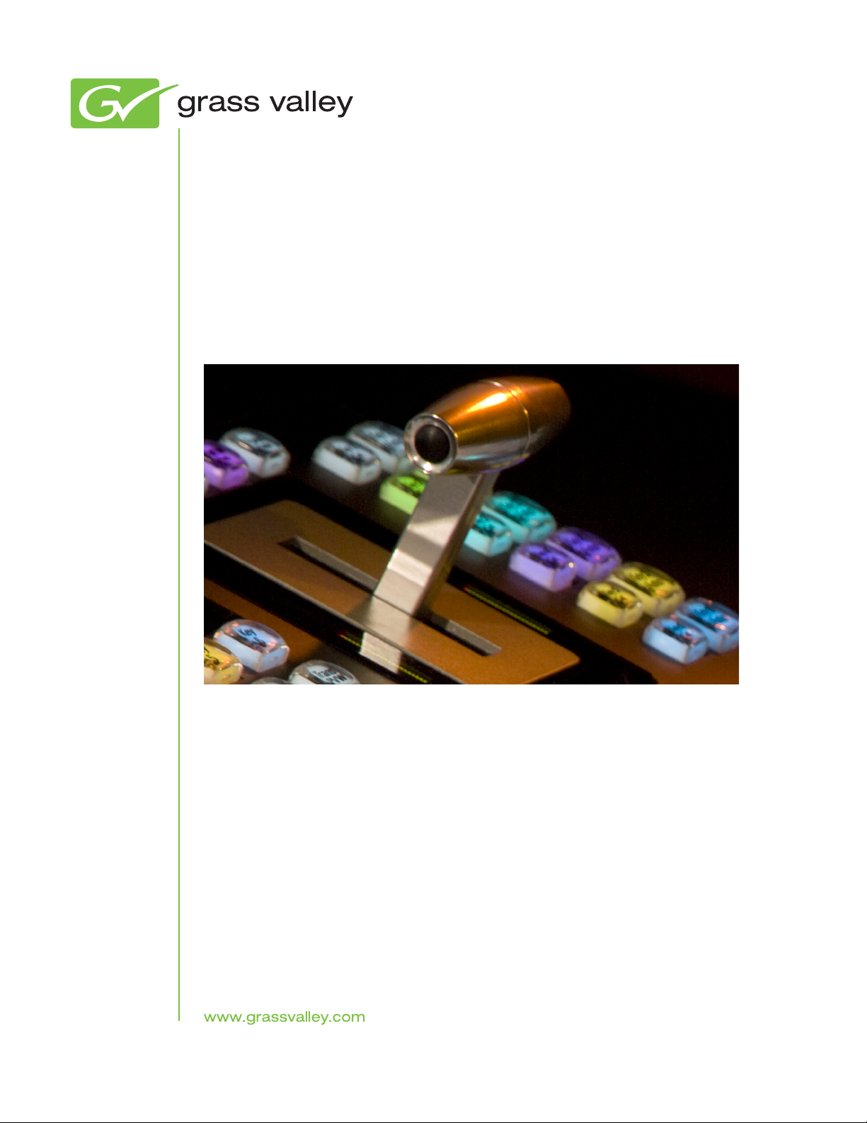
K-Frame Video Processor
The K-Frame Video Processor is available in two sizes (Figure 1). The
number of licensed boards present in the frame determines the number of
20 KAYENNE K-FRAME — User Manual
Page 21
MEs available, as well as the number of video inputs, outputs, GPIOs and
8875_01
K-Frame 13-RU
Video Processor
K-Frame 6-RU
Video Processor
Frame Power Supply 1-RU
(1 for each K-Frame)
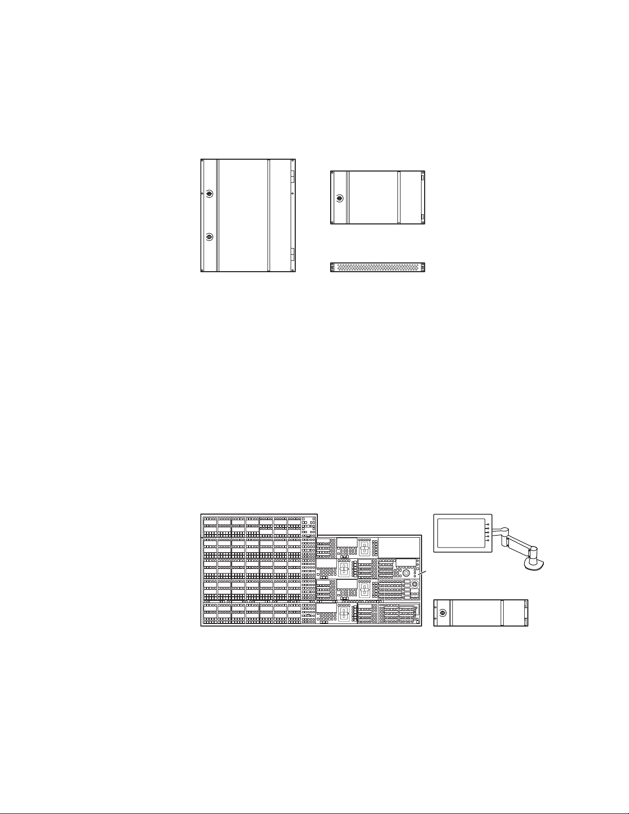
4-ME 35 Control Panel Menu Panel
Menu Panel
Articulated
Arm
8623266_01
Panel Control Unit (PCU)
Optional Device
Control Module
Optional
Module
Relay Tallies.
Figure 1. K-Frame Video Processors
K-Frame Control Surfaces
K-Frame Control Surfaces
Kayenne
KAYENNE K-FRAME — User Manual 21
A Kayenne control surface typically consists of a Control Panel, a Menu
Panel with an included articulated support arm, a Panel Control Unit
(PCU) frame, and optional Satellite Panels. This control surface has an
innovative modular design. Representative Kayenne control surfaces are
shown in the following illustrations.
Figure 2. Kayenne 4-ME 35 Control Surface
Page 22
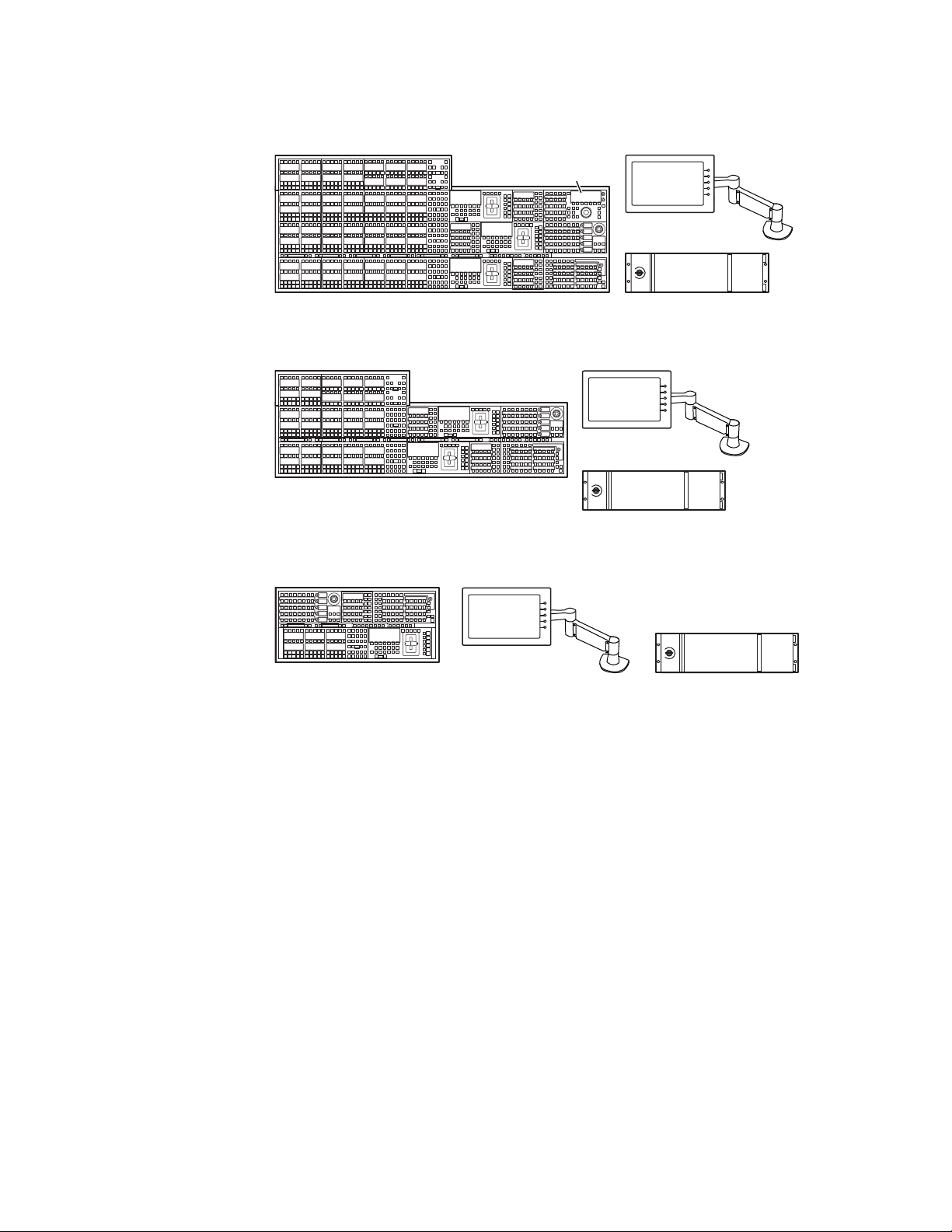
Section 1 — Introduction
Menu Panel
Menu Panel
Articulated
Arm
8623266_02
Panel Control Unit (PCU)
3-ME 35 Control Panel
Optional Device
Control Module
Menu Panel
Menu Panel
Articulated
Arm
8623266_03
Panel Control Unit (PCU)
2-ME 25 Control Panel
Menu Panel
Menu Panel
Articulated
Arm
8623266_04
Panel Control Unit (PCU)
1-ME 15 Control Panel
Figure 3. Kayenne 3-ME 35 Control Surface
Figure 4. Kayenne 2-ME 25 Control Surface
Figure 5. Kayenne 1-ME 15 Control Surface
The modular design and use of a separate PCU supports the hot-replacement of individual Control Panel components, if necessary, while the rest
of the system remains operational.
Flat or Curved Control Panel Orientation
The main Kayenne Control Panel supports different physical orientations.
Besides a conventional flat surface, a special support design permits a
curved working surface, where the MEs progressively tilt for improved
ergonomics (
Figure 6).
22 KAYENNE K-FRAME — User Manual
Page 23
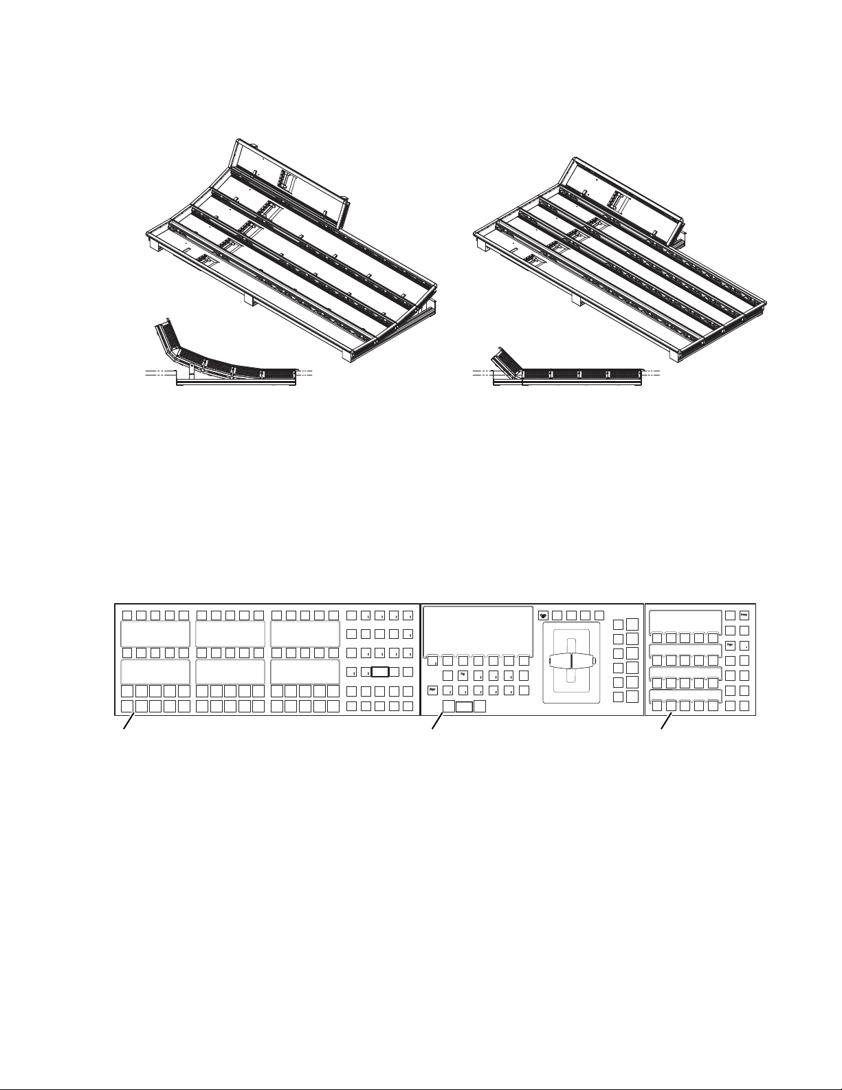
Figure 6. Curved and Flat Control Surface Installations
Flat Control Panel AssemblyCurved Control Panel Assembly
HoldHold
HoldHold
A
HoldHold
BU1U2
HoldHold
FarFarKeyKey
SplSplit
RulesRules
HoldHold
EMEMEMEM
SecSec
Aux
Pri
KeyKey3KeyKey
1
MacroMacro
KeyKey
5
KeyKey4KeyKey
2
RtrKeKey
6
EMEMEMEM
MaMacroro
RevRev
RwdRwd
RunRun
Transans
RateRate
Auto
Run
Run
Panelnel
MemMem
MeMenu
Mix
Transns
PVW
Transans
Rate
EMEMEMEM
Runun
Ptnt n
LimLimi t
Pst
BLK
KeyKey1KeyKey2KeyKey3KeyKey4KeyKey5KeyKey
6
KeKey1
CutCut
KeKey2
CutCut
KeKey4
CutCut
KeKey3
CutCut
KeKey6
CutCut
KeKey5
CutCut
KeKey 1
Auto
Auto
KeKey 2
Auto
Auto
KeKey 3
Auto
Auto
KeKey 4
Auto
Auto
KeKey 6
Auto
Auto
CutCut AutoAuto
KeKey 5
Auto
Auto
Userer5Userer
6
Userer4Wipeipe2Wipeipe
1
Userer3Userer2Userer
1
Key
Prior
8623266_54
Source Module (35, 25, or 15) Local E-MEM ModuleTransition Module
Control Panel Stripes
K-Frame Control Surfaces
The main Kayenne Control Panel is organized into from one to five Stripes.
Each Stripe consists of a tray and its complement of drop-in modules. An
ME Stripe has a module for Source Selection, Transition, and individual
E-MEM control (Figure 7). Additional Master E-MEM, Machine Control,
Multi-Function, and Local Aux modules are populated to complete the
control surface functionality.
Figure 7. Portion of Control Panel ME Stripe
Touch Screen Menu Panel
Each Kayenne control surface includes a Menu Panel that features a wide
format 15 in. touch screen display. An articulated arm is also included,
offering a wide variety of installation options (Figure 8). The Menu Panel
has a standard VESA-75 hole pattern and M4 threads, compatible with this
and many other mounting devices.
KAYENNE K-FRAME — User Manual 23
Page 24
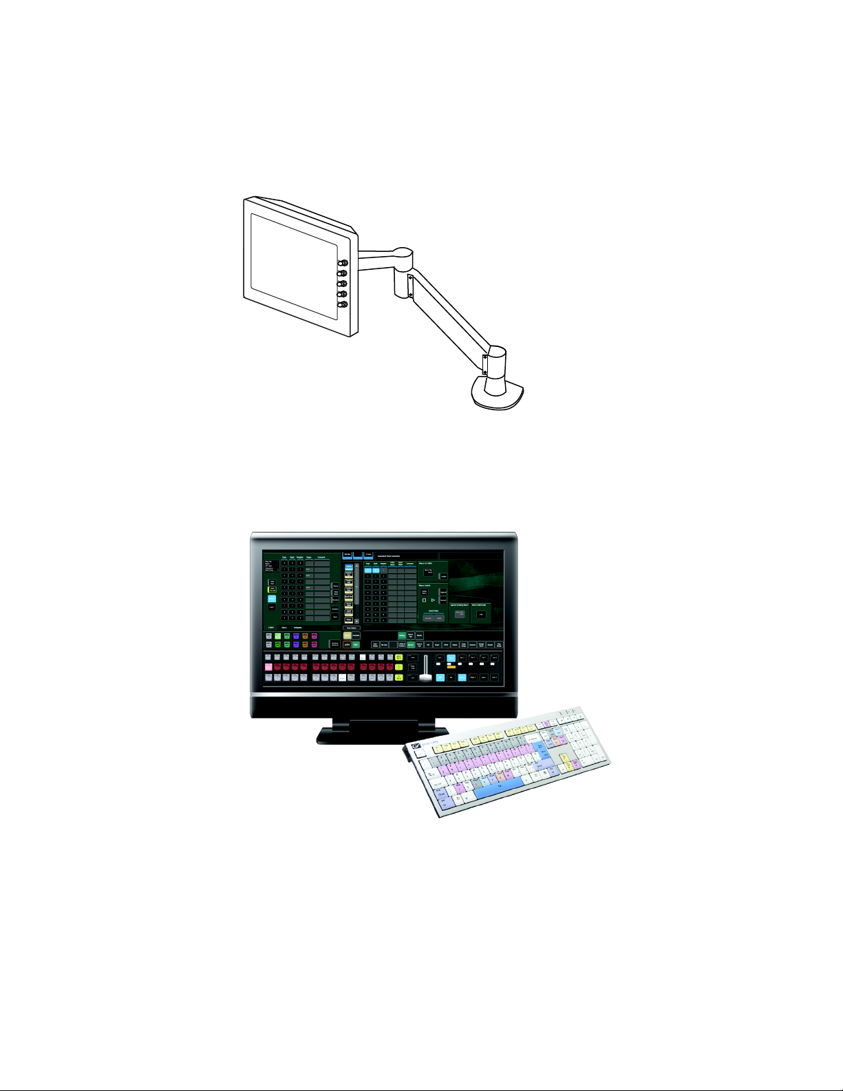
Section 1 — Introduction
The Menu Panel has four USB ports, two on the right side edge of the panel
and two on the back for keyboard and mouse (wired or wireless are sup
ported).
Figure 8. Menu Panel with Articulated Arm
8623266_05
-
Soft Panel (KSP) Option
Figure 9. Soft Panel Application
The KSP is an optional 1-ME Soft Panel GUI which provides direct control
of switching crosspoints, recalling effects and macros together with an inte
grated version of the Menu application. A customized PC keyboard is
included with the option for users who like quick cut and mix action from
a hard-button interface. The KSP can be used as an adjunct to a main panel,
providing a second seat (second control surface) in a Suite, or as the only
control surface for a second Suite.
-
24 KAYENNE K-FRAME — User Manual
Page 25
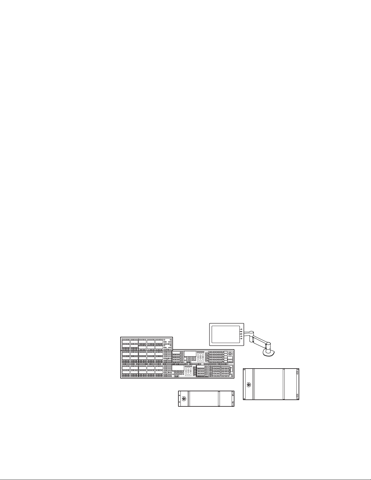
The KSP GUI application is designed to run on a PC platform. The screen
Menu Panel
Panel Control Unit (PCU)
2-ME 25 Kayenne Control Panel
8877_01
Compact 6-RU K-Frame
must be 1920x1080 resolution or better (which is common in professional
video environments). A touchscreen is not required, but can be very useful.
The KSP software is included with the switcher application software. Purchasing the option provides a software license that enables the interface for
the selected switcher, and includes a customized PC keyboard. The license
activates an unlimited number of KSP applications associated with the
licensed video processor frame. Additional customized PC keyboards are
also available for purchase.
Menu Application
The Menu application software provided with every K-Frame system can
be run on a standard PC. This software accesses all the system’s function
ality, permitting mouse and keyboard control from a laptop, or remote
control from any location on the network.
K-Frame System Examples
-
K-Frame System Examples
Basic Single Suite Kayenne Panel System
A basic K-Frame system consists of a Control Panel, a Menu application
running on a touch screen Menu Panel, and a Video Processor Frame. The
Control Panel and Menu application make up a control surface associated
with that frame. (
have associated active electronics housed in the Panel Control Unit (PCU).
Figure 10. Kayenne Single Suite Compact Frame Example
Figure 10). The Kayenne Control Panel and Menu Panel
KAYENNE K-FRAME — User Manual 25
Page 26

Section 1 — Introduction
Multiple Suite Kayenne Panel System
A K-Frame system can be subdivided into two suites, if desired, each of
which can have two control surfaces (Surface A and Surface B). Each
surface has it's own set of Panel Preferences for configuration of the control
panel behavior and independent macro systems to allow for independent
building and running of macros by each operator at the control surface.
Hardware resources in the Video Processor Frame can be assigned to an
individual suite during configuration, essentially creating two separate
switchers sharing one frame (
Figure 11. Kayenne Multi-Suite Standard Frame Example
Figure 11).
Suite 1
4-ME 35 Kayenne Control Panel
KSP 1-ME
Soft Panel Option
(Customer Supplied PC)
Suite 2
2-ME 25 Kayenne Control Panel
Menu Panel
Panel Control Unit (PCU)
Menu on PC
(Customer Supplied PC)
Menu Panel
Standard 13-RU
K-Frame
Panel Control Unit (PCU)
8875_20
26 KAYENNE K-FRAME — User Manual
Page 27

Supported Control Protocols
• Ethernet
• PBus II
•GPI Inputs and Outputs
• Serial BVW-75 for VTR control
• Odetics protocol for VTR control
• AMP (advanced media protocol) for Profile PVS, Profile XP Media Plat-
form, K2, M-Series, Turbo iDDR, and T2 iDDR systems over Ethernet
• Grass Valley Native Protocol for routers/routing control systems
(Trinix/Trinix NXT, Venus™, Triton™, and third-party routers; Jupiter
and Encore router control systems)
• Tally (contact closure)
• K-Frame Ethernet Tally protocol
• Ethernet CPL to control Grass Valley external remote AUX Panels
Supported Control Protocols
• Grass Valley Editor protocol
• SNMP system monitoring
• Serial and Ethernet VDCP
• LDK Series & LDX Series™ camera control with Ethernet tally via
Connect Gateway
KAYENNE K-FRAME — User Manual 27
Page 28

Section 1 — Introduction
28 KAYENNE K-FRAME — User Manual
Page 29

Setting Panel Preferences
Control Panel Source Select Button Mapping
Video sources can be assigned or “mapped” to Control Panel Source Selection buttons, referred to as “Button Mapping”, on each Control Panel
Mix/Effects (ME) bank and the Local Aux Panel. The same source can be
mapped to one or many buttons. Button mapping is also used to assign
Aux buses to delegation buttons, referred to as “Aux Delegate Button Map
ping”.
Source Select buttons on the Grass Valley Video Production Control Panel
and Local Aux can be changed from the defaults to best suit how you work.
Technical Directors often map groups of sources together, like cameras,
character generators, Image Store and ClipStore Channels, and other kinds
of like sources, or a TD may setup the source select buttons in the order they
plan to switch a show.
Section 2
-
Button mapping settings are included as part of Panel Preferences, and can
be saved and instantly loaded for use at any time from the File Ops, User
Setups menu.
Note If a GV Switcher system’s NV memory is cleared, the button mapping for the
Control Panel and Local Aux will revert to the factory defaults.
KAYENNE K-FRAME — User Manual 29
Page 30
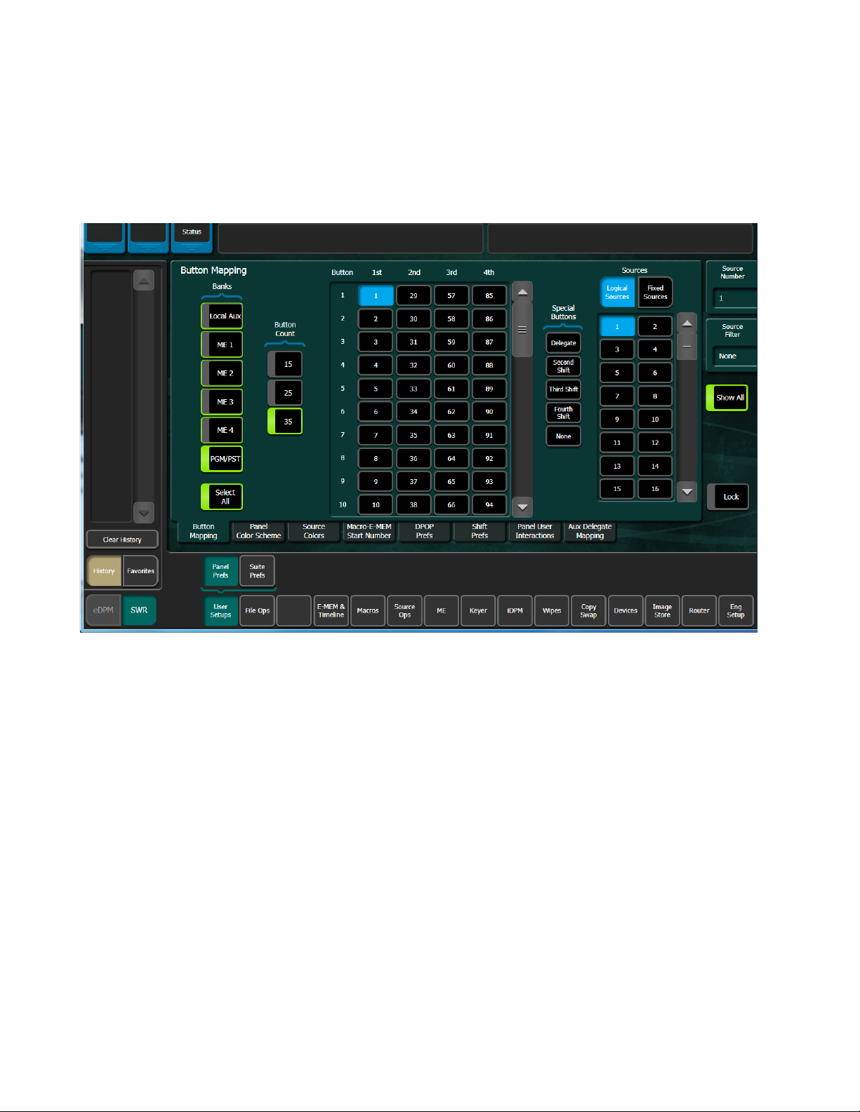
Section 2 — Setting Panel Preferences
The Button Mapping Menu
Access the Button Mapping menu by touching User Setups, Panel Prefs, Button
Mapping
Figure 12. Button Mapping Menu, Logical Sources
.
The following describes the menu area and button functions of the Button
Mapping menu (
• Bank toggle buttons are used to select one, several, or all MEs and/or
Local Aux (includes the
selected are assigned to any Banks buttons toggled to on in the Banks
button row.
• Whichever Bank buttons are on when a Logical or Fixed Source is
selected for assignment, the source select buttons for those banks are
assigned that selection.
Figure 12):
Select All button). Logical/Fixed sources
30 KAYENNE K-FRAME — User Manual
Page 31

The Button Mapping Menu
• Button Count buttons (15, 25, and 35) are used to select the button count
for the Control Panel. For example if the menu has not been associated
with a Control Panel or if using a 15 or 25 button Control Panel with a
35 button Aux Panel, the button count can be selected manually (this
selection is automatic if a panel has been associated in the
data pad, in the Eng Setup, Node Settings, Frame Suite Nodes &
Panel
ID menu).The Source Select button scrolling list allows you to select a
source select button to assign a source from the Logical/Fixed Sources
list.
Special Buttons are used to assign Delegate and Shifted Levels to Source
Select buttons:
• Delegate button is used to assign the Keyer and Bus Row delegations to
source select buttons.
Second Shift, Third Shift, and Fourth Shift buttons are used to assign those
•
shift levels to source select buttons.
Same as 1st button is used to assign the source from the first level on a
•
bus to another shifted level for that bus (Second, Third, or Fourth).
Associated
None button assigns the selected source select button as unmapped.
•
When a Special Button is selected as a mapped source for a Source Select
button, that assignment will be given to each level of that bus; each can be
changed individually afterward.
KAYENNE K-FRAME — User Manual 31
Page 32

Section 2 — Setting Panel Preferences
The Logical/Fixed Sources section is used to search and assign sources:
• Sources scrolling list is used to locate assignable sources. You can choose
from Logical Sources (Figure 12), or Fixed Sources (Figure 13).
Figure 13. Button Mapping Menu, Fixed Sources
• Source Number data pad displays a data entry pop-up when selected and
is used to assign a Logical source number to a source select button.
Source Filter data pad displays a data entry pop-up when selected and is
•
used to perform an alpha-numeric, case sensitive search of Logical or
Fixed sources.
Show All button displays all sources in the scrolling list.
•
Lock button locks the scrolling list; helpful for selecting multiple, adja-
•
cent sources.
32 KAYENNE K-FRAME — User Manual
Page 33

Default Control Panel Source Select Button Mapping
Default Control Panel Source Select Button Mapping
Table 1. 3-ME Factory Configured Source to Button Mapping 1st and 2nd Levels
Panel Button
Buttons 1-28 Source 1 - 28 Source 29 - 56
Button 29-32 M1 A - M4 A M1 C - M4 C
Button 33,34 Shift, Shift Shift, Shift
Button 35 Delegate Delegate
Ta bl e 2 shows the 3rd shifted level.
Table 2. 3-ME/35 Factory Configured Source to Button Mapping 3rd Level
Panel Button (35) 3rd
Buttons 1-28 Source 57 - 84
Button 29-32 M1 B - M4 B
Button 33,34 Shift, Shift
Button 35 Delegate
1st
(unshifted)
2nd
Ta bl e 3 shows the 4th shifted level.
Table 3. 3-ME/35 Factory Configured Source to Button Mapping 4th Level
Panel Button (35) 4th
Button 1-12 85-96
Button 13-18 IS 1A - IS 6A
Button 19 eDA
Button 20 eDC
Button 21-24 Pg A - Pg - D
Button 25 Blk
Button 26 Test
Button 27,28 Bg 1,Bg 2
Button 29-32 M1 D - M4 D
Button 33,34 Shift, Shift
Button 35 Delegate
Ta bl e 4 shows the source to button mapping for the 1st (unshifted) and
second levels for a 25 button 2ME system.
Table 4. 2-ME/25 Factory Configured Source to Button Mapping 1st and 2nd Levels
Panel Button (25)
Button 1-18 Source 1 - 18 Source 19 - 36
Buttons 19-22 M1 A - M4 A M1 C- M4 C
1st
(Unshifted)
2nd
KAYENNE K-FRAME — User Manual 33
Page 34

Section 2 — Setting Panel Preferences
Table 4. 2-ME/25 Factory Configured Source to Button Mapping 1st and 2nd Levels
Panel Button (25)
Button 23, 24 Shift, Shift Shift, Shift
Button 25 Delegate Delegate
Ta bl e 5 shows the source to button mapping for the 3rd level for a 25 button
2ME system.
Table 5. 2-ME/25 Factory Configured Source to Button Mapping 3rd Level
Panel Button (25) 3rd
Button 1-18 Source 37 - 54
Buttons 19-22 M1 B- M4 B
Button 23, 24 Shift, Shift
Button 25 Delegate
Ta bl e 6 shows the source to button mapping for the 4th level for a 25 button
2ME system.
1st
(Unshifted)
2nd
Table 6. 2-ME/25 Factory Configured Source to Button Mapping 4th Level
Panel Button (25) 4th
Button 1,2 Source 55,56
Buttons 3-8 IS 1A - IS 6A
Buttons 9,10 eDA, eDC
Buttons 11-14 Pg A - Pg D
Button 15 Blk
Button 16 Test
Buttons 17,18 Bg 1,Bg 2
Buttons 19-22 M1 D - M4 D
Button 23, 24 Shift, Shift
Button 25 Delegate
Setting Control Panel Source Select Button Mapping Preferences
Before setting Control Panel source select button mapping preferences,
Source Names have been defined in the Eng Setup, Source Definition menu
and Image Store channels are assigned to Aux Busses.
1. Tou ch User Setups, Panel Prefs, Button Mapping (Figure 14).
34 KAYENNE K-FRAME — User Manual
Page 35

Assigning Colors to Control Panel Source Select Buttons
Figure 14. Button Mapping Menu
2. Touc h t he PGM/PST Button Mapping Bank button. (Notice that a Select All
button is available below the list of bank buttons.)
3. touch the bank source button to be mapped in the center pane.
4. Touch the desired source in the right pane on the right. Select from
Logical or Fixed sources.
Result: As the button mappings change, the new source names will
appear on the source name displays of the source selection buttons on
the Control Panel and/or Local Aux.
Assigning Colors to Control Panel Source Select Buttons
The Control Panel Source Select buttons, including Delegate and Shift buttons, can be changed from the Control Panel color scheme to display userdefined colors (red, green, blue, light red, light green, cyan, magenta, etc.).
1. Tou ch User Setups, Panel Prefs, Source Colors (Figure 15).
KAYENNE K-FRAME — User Manual 35
Page 36

Section 2 — Setting Panel Preferences
Figure 15. Source Colors Menu
2. Select the Logical ID of the desired source (use Multi-Select button for
multiple selections).
3. Select the desired color in the System Colors pane.
4. Selecting the Invert button displays dark text over a colored background
in the Source Select Area display OLEDs (default is colored text over
dark background).
Assigning User-defined Colors
The User Color buttons allow you to create custom colors for Source Select,
Delegate, and Shift buttons.
1. Tou ch User Setups, Panel Pref (Figure 15).
2. Touch the number of the Logical ID in the scrolling list or enter the
number in the Logical ID pop-up keypad by touching the Logical ID
data pad (use
3. Touch a User Colors button User 1-User 5.
4. Adjust the User Color by turning the Red, Blue, and Green Menu Panel
soft knobs or by touching their data pads and entering a value in the
pop-up keypad (
Multi-Select button for multiple selections).
Figure 15, right).
36 KAYENNE K-FRAME — User Manual
Page 37

Mapping Remote Aux Panel Source Select Buttons on the Control Panel
Mapping Remote Aux Panel Source Select Buttons on the
Control Panel
The Remote Aux Panel Server Ethernet IP is set to the Video Processor
Frame of the GV Switcher system, in the Panel Network Configuration web
page and the Remote Aux appears in the Aux Panel Name column in the
Eng Setup, Node Settings, Remote Aux IP Network menu. Refer to the
Remote Aux Panel topics in the Installation & Service Manual for your
switcher model for more information.
1. Tou ch Eng Setup, Node Settings, Remote Aux Button Map.
Figure 16. Remote Aux Button Map Menu
2. Select an individual Remote Aux Panel by touching its button in the left
pane or select the
Settings menu.
3. Map the source buttons for the selected Aux panel(s) by selecting the
Aux source button in the central pane, then selecting the source in the
right pane.
Multi Select button for group selection of the Node
KAYENNE K-FRAME — User Manual 37
Page 38

Section 2 — Setting Panel Preferences
Mapping Remote Aux Panel Delegation Buttons
You can map Remote Aux buses to Panel Delegation buttons to make them
available as sources to the GV Switcher Control Panel.
Aux Delegate button mapping is performed in the Eng Setup, Node Settings, Remote Aux Bus Button Map menu. When multiple Remote Aux
Panels are selected, changing one button’s mapping changes the button
mapping for all the selected Remote Aux Panels.
1. Tou ch Eng Setup, Node Settings, Remote Aux Logical Map (Figure 17).
Figure 17. Remote Aux Bus Delegation Button Mapping Menu
2. In the Panel Delegation area, touch a Remote Aux Panel button.
3. In the Logical Aux Buses area, touch an Aux Bus delegation button.
Note Button mapping settings for Remote Aux Panels are saved to the Eng Setup
configuration file.
38 KAYENNE K-FRAME — User Manual
Page 39

Setting Suite Preferences
About Source Patching
Facility engineers need to know the exact routing of all the video signals
connecting all the devices they are responsible for. These engineers need to
be able to identify video signals in a way that will help them connect
devices properly. Production personnel, on the other hand, are interested in
the content they work with for their shows, and are generally not con
cerned about which individual device or routing path is used to make those
signals available. They just need a way to identify the content and access it
when they need it. To support these differing needs, two source naming
mechanisms are available on GV Switcher systems; Engineering Source ID
and Logical ID.
By default engineering source IDs are mapped one-to-one with logical IDs
but Source Patching can be used to quickly set up production elements for
use in a different facility. For example, a show’s effects, DDR clips, and
taped material may have been built in one production truck with one set of
devices, but the next show is scheduled for a different truck. Previously, to
use effects in the other truck the Technical Director (TD) would need to edit
the engineering source definitions in the new truck so they exactly matched
the old truck. By remapping the engineering sources of the devices in the
new truck to the logical sources used to build the effects, all the effects can
be used without having to edit them. Source Patching can also be used to
quickly swap out a defective device during a show without having to
reconfigure the engineering sources. In this case logical names seen by the
production personnel would be identical for that content, even though the
actual device playing the material changed.
Section 3
-
Note Source Patching is the bridge between engineering sources and logical
sources. Both TD and EIC should make reference to the Source Patch menu
when resolving source issues. The mechanism is similar in concept to a
physical patch panel. Effects and all source selections a
sources. Tally and associations with external devices are based on engi-
neering sources.
The Source Patch menu (Figure 18) scrolling list has more Logical IDs than
physical inputs. These can be used to permit alternative processing of the
same incoming signal. For example, the same camera input can be assigned
KAYENNE K-FRAME — User Manual 39
re based on logical
Page 40

Section 3 — Setting Suite Preferences
to two Logical IDs, and one of these Logical sources can be given a Source
Rule that can be cut on Key 5, and the other be given a Source Rule that cuts
on Key 6. Selecting these different versions of that same source would auto
matically apply or clear the keys, as needed.
Figure 18. Source Patch Menu
-
Engineering Names, Eng IDs, and Logical IDs
Engineering names are intended to identify a source as it applies to a specific facility. In a truck, for example, cameras may be hard wired to the production switcher and might be given Engineering names 1, 2, and 3. Names
like Patch
Engineering names are entered in the Eng Setup Source Definition menu,
as described above. Engineering source IDs are numeric only, and are avail
able on data pads and scroll knobs for quick selection. The GV Switcher
system also has logical IDs, that can be used for source patching, as
explained later.
14 or Rtr 5 may be used for inputs that are patched or routed.
Alternative Source Names
Alternative names can be assigned to sources for the convenience of production personnel. For example, you may give the cameras menu names
that include the operator (C1
Bob, C2 Phil, and C3 Bill), but remove the
-
40 KAYENNE K-FRAME — User Manual
Page 41

operator names from the OLED names to show C1, C2, and C3 in larger
characters. These alternative names are entered in the Source Patch menu.
The Source Patch menu (Figure 19) has three editable columns for defining
up to three alternative names:
A Panel Name is limited to four characters, to fit the space available on the
Control Panel’s Transition Area. This name is only displayed on the Control
Panel.
An OLED Name appears only on the Source Name Displays on the Control
Panel. Up to eight characters are displayed.
A Menu Name is limited to eight characters, and appears on all the GV
Switcher menu application screens except Engineering Setup menus,
which always display engineering IDs or names.
Multiple Suites and Source Names
Different sets of these alternative source names are defined for each GV
Switcher suite. Ensure the GV Switcher Menu Application you are using is
logged into the correct suite (
neering names will be used by both GV Switcher suites, however.
About Source Patching
Eng Setup, Eng Logon). The same set of engi-
Source Name Display Hierarchy
If a source’s engineering name is left blank, the Eng ID number will be
used. If no alternative names are defined for that source, then that Eng ID
number will appear on all the GV Switcher system displays.
If an engineering name has been entered (see the GV Switcher Installation
& Service Manual for your model) then the engineering name will be dis
played on all the GV Switcher system displays, including menus. Engineering names will be truncated to the character limits of the display,
starting with the first character.
For alternative names entered in the User Setups, Suite Prefs, Source Patch
menu (
For the three editable columns: Panel Name, OLED Name, and Menu Name, if any
of the three are left blank for that source, the first name to the left appears
in that display on the system (if all three are left blank, the name in the Eng.
Source Column is displayed). For example, if an alternative name is entered
in the OLED Name column for a source and the other two columns remain
blank, the Menu Name takes the OLED Name (OLED Name being first to
the left of the Menu Name) but the Panel Name takes the Eng. Source
column’s name (first name to its left). If names are entered in all three alter
native name columns, each area of the system displays the name entered in
each column of the Source Patch menu (
Figure 19), the following rules apply:
-
-
Figure 19).
KAYENNE K-FRAME — User Manual 41
Page 42

Section 3 — Setting Suite Preferences
Transition Area
If Menu Name is
left blank menus
use first entry to
the left
Menu Source
Lists
Figure 19. Source Patch Alternative Source Names
It is a good practice to create the least number of names possible. This
ensures consistency in the various displays and reduces the time needed to
enter and edit the names. If you can create short engineering names that
work for both the production staff and engineering, complete naming con
sistency is assured. However, this level of simplicity is probably only feasible at a fixed installation where all the shows use the same source names.
When multiple names are created, try to keep the first four characters
unique, and make different names for the same source similar for ease of
recognition.
Source Patching and Effects Portability
Source patching makes it possible to build effects on a GV Switcher system
in one facility or truck, and then use those effects on a different system at
another facility that has different Engineering source configurations.
Building a Source Patch table prior to effects creation simplifies the migra
tion of effects between facilities.
Plan out the sources you will use for a show, even ones that may not exist
on the system where you are creating the effects. Build a list of Logical
sources in the Source Patch menu without regard to the currently associ
ated Engineering sources. After the list is built, map one of the facility’s
existing Engineering sources to each Logical source. If physical devices
don't exist for some planned sources, substitute a dummy Engineering
source. You can then build your effects and verify that they run properly.
When you are satisfied with the effects, save the Suite Prefs and E-MEM
-
-
-
42 KAYENNE K-FRAME — User Manual
Page 43

Patching Engineering and Fixed Sources to Logical IDs
effects you created to USB Memory Stick. At the new facility, load these
files into that GV Switcher system. Do not load the Eng Setups of one
facility into the other, as this will overwrite that facility’s existing Engi
neering configuration.
Once the Suite Prefs and effects are loaded at the new facility, go to the
Source Patch menu and map the appropriate Engineering sources of the
new facility to the original list of Logical sources. Your effects should now
run as previously designed without having to edit or rebuild them. When
satisfied the effects run correctly at the new facility, save that Suite Prefs
under a different name for use the next time you use this facility. Do not
overwrite the original Suite Prefs, as you will need it when you return to
the original facility.
Patching Engineering and Fixed Sources to Logical IDs
1. Tou ch User Setup, Suite Prefs, Source Patch (Figure 20).
-
Figure 20. Source Patch Menu
2. Touc h t he Eng Sources/Fixed Sources button to select a source type.
KAYENNE K-FRAME — User Manual 43
Page 44

Section 3 — Setting Suite Preferences
3. Select the Logical ID of the source you wish to change by either:
• Touching the Logical ID data pad (Figure 20) and entering the
• Scrolling through the Source Names list with the scroll bar. This
4. Give sources alternative names in the Source Patch menu in the
following ways (
• Panel Name —Source will appear in the Transition and Multi-Function
displays with this name,
• OLED Name (SND Name column)—Source Name Display will appear
in mapped ME/PGM PST Source Select and the Multi-Function displays with this name,
• Menu Name (Menu Name column)—Source will appear with this
name in the menus only.
Logical ID number, or
scrolls the list without changing the current selection. When the
desired source appears on the menu, touch its Logical ID button to
select it. Use the
Lock button to lock the scroll bar.
Figure 20):
To change the source patching, select an Engineering/Fixed source to be
associated with the currently selected Logical source with the Engineering
Source data pad or by scrolling the Engineering Source IDs Button pane
(
Figure 20).
Enable Source Correction on any Source (Globally)
Using Source Corrections, in the User Setups, Source Patch menu (or the
Source Corrections menu), you can enable source correction for a patched
Engineering to Logical source. The source correction is global; anywhere
the patched source is mapped on the switcher. Source Correction is saved
as part of File Ops, User Setups, Suite Prefs and can be included/excluded.
Note Enabled Source Correction on a source is not E-MEMable, however patching
a source on an ME, from the Source Corrections menu, is E-MEMable.
1. Choose the source and enable Source Correction:
a. In the User Setups, Suite Prefs, Source Patch menu, touch the Enable
button to the right of the desired Source Patch row, or
b. In the Source Correction menu, touch the Logical Name data pad and
enter the Logical ID in the pop-up keypad then turn on the Source
Correction
Enable button.
2. Adjust the parameters for Video Processing and RGB Color Correction
in the Source Correction menu.
Note The same Engineering source can have Source Correction enabled or dis-
abled by patching the source to a different logical ID.
44 KAYENNE K-FRAME — User Manual
Page 45

Patch a Key Input from One Source to a Different Source Using Patch Key
Patch a Key Input from One Source to a Different Source
Using Patch Key
You can patch a key from a different source using Patch Key.
1. Tou ch User Setup, Suite Prefs, Source Patch (Figure 21).
Figure 21. Source Patch Menu
2. Touch the data entry pad in the Patch Key column for the Logical ID
you wish to patch a key from a different source.
3. Touch the Eng or Fixed source in the Sources scrolling list containing
the key you wish to patch (LOGO KEY in the example in
press the Patch Key Source ID data pad and enter the Source ID number for
the key you wish to patch, and press
Result: The key signal for Logical ID 19 (LOGO KEY) is now paired with
the Logical ID 16 (RED VID) video signal (
Example: The example in Figure 20 shows three different video sources
over the same key signal, in this case the station logo. The three logos are
defined as RED LOGO, BLU LOGO, and GRN LOGO in the menus and as
RLGO, BLGO, and GLGO in the Panel Name which will be displayed on
the OLEDs of the keyer source select buttons when assigned to the Control
Panel.
Enter.
Figure 20).
Figure 20) or
KAYENNE K-FRAME — User Manual 45
Page 46

Section 3 — Setting Suite Preferences
Default Keyframe
Default Keyframe settings are applied when an empty register is recalled
and when the
E-MEM (
• SPOP (Single Press) clears the working buffer of enabled levels to Default
Keyframe, however it does not clear the source memory.
DPOP (Double Press) clears the working buffer of enabled levels to Default
•
Keyframe and clears the source memory to the default settings for
sources selected on enabled levels.
The Default Keyframe menu is used to learn the current Control Panel state
to the system’s Default Keyframe (and to set the Default Keyframe back to
factory settings). Individual settings for each ME are stored in the Default
Keyframe, so different states can be saved for different MEs, if desired.
Note Individual Default Keyframe settings are saved for each GV Switcher ME.
CWB (Clear Wo rk in g Buffer) button is pressed in the Master
EMEM Edit, CWB button) of the Control Panel.
46 KAYENNE K-FRAME — User Manual
Page 47

Learning a Default Keyframe
1. Tou ch User Setups, Suite Prefs, Default Keyframe (Figure 22).
Figure 22. Default Keyframe Menu
Learning a Default Keyframe
2. Setup the Control Panel to the desired state.
3. Press the Learn button in the Default Keyframe pane.
Pressing the Set button overwrites the Default Keyframe with factory
defaults.
Note Save your current Suite Prefs, which includes the Default Keyframe settings
before resetting to factory defaults.
KAYENNE K-FRAME — User Manual 47
Page 48

Section 3 — Setting Suite Preferences
Preview Prefs
Preview displays can be adjusted by the user, including Safe Area borders,
Crosshairs, and the selection of optional multi-image ME Viewer layouts.
Figure 23. Preview Prefs Menu
Safe Area
• Preview Prefs buttons on the left select the ME or Switched Preview that
will be affected by the settings on the right. Each ME has Primary and
Secondary Preview parameters for Safe Area and Crosshairs, and an
ME Viewer layout. Switched Preview has a single set of parameters for
Safe Area and Crosshairs.
• Safe Area button, when illuminated, activates the Safe Area border
display for the selected preview.
Set Safe Area data pad displays knob controls on the right used to move
•
the Safe Area borders.
Action, SMPTE Title, EBU Title buttons sets the safe area borders to those
•
standards.
48 KAYENNE K-FRAME — User Manual
Page 49

Crosshair
• Crosshair button, when illuminated, displays a Crosshair for the selected
•
•
About ME Viewer
The K-Frame ME Viewer optional feature provides a special source from
each ME that can be used to display multiple ME signals on a single mon
itor. Each ME has a fixed source named (ME) pM (ME = 1-4 or Pg). This
source can be assigned one of six multiple signal arrangements, in User
Setups/Suite Prefs. Assigning this source to a physical output connector
permits viewing that arrangement of signals on a monitor.
Preview Prefs
preview.
Crosshair data pad displays knob controls on the right used to adjust the
position of the Crosshair.
Set to Default restores the default center position for the Crosshair.
-
KAYENNE K-FRAME — User Manual 49
Page 50

Section 3 — Setting Suite Preferences
Previews
Programs
Previews Programs
Primary Secondary Keys
Programs Previews Keys
Primary Previews Programs Keys
Figure 24. Examples of ME Viewer Displays
About Multiviewer Preferences
The K-Frame Multiviewer provides five layout configurations, tally preference settings, assignable Fixed and Logical inputs, Switched Preview, or
Aux Buses to each video window. Multiviewer menu preferences are saved
as part of Suite Prefs and can be loaded or excluded as part of the Load
Granularity in the File Ops, Eng Setup menu.
Prerequisite: Multiviewer resources have been allocated and configured,
see the Installation & Servicie Manual for your switcher model.
50 KAYENNE K-FRAME — User Manual
Page 51

Set Multiviewer Layout Preferences
Choose from one of five Multiviewer layouts.
1. Select the User Setups, Suite Prefs, Multiviewer Prefs menu buttons.
2. If there is more than one Multiviewer acquired, press the Identify button
to display the available Multiviewers in the top, middle of the monitor
so the correct Multiviewer will be selected for adjustment.
3. Select a Multiviewer to apply the preferences; buttons MV1-MV4 below
the layout configuration pane.
Figure 25. Eng Setup, Acquire Multiviewer—Standard Frame
About Multiviewer Preferences
4. Select a layout from the Layout list on the left side of the menu.
5. Select a window in the Multiviewer layout.
6. Select Logical or Fixed above the scrolling list on the right of the menu.
7. Scroll or filter to an input and select that input to assign it to the selected
window.
The window name is taken by default from the Eng Sources name but will
take the Menu name if entered in the User Setups, Suite Prefs, Source Patch
menu for the selected source.
KAYENNE K-FRAME — User Manual 51
Page 52

Section 3 — Setting Suite Preferences
8. To enter a name in the Menu column of the Source Patch menu to
change the window name:
a. With the source assigned and the window selected in the
b. Select the Source Patch menu tab.
c. Locate the noted source by either scrolling through the Source list
d. Select the Menu column data pad for the source and enter the new
e. Select Enter.
9. Repeat selecting windows then input sources for additional
assignments.
10. Turn off the Identify feature if on as it can obstruct some of the views.
Multiviewer Prefs menu, note the Source Number in the upper
right data pad.
(Logical ID column) or clicking on the Engineering Source ID data
pad and entering the Source Number noted from the Multiviewer
Prefs menu.
name in the pop-up keyboard.
File Operations
Note It is not recommended to have the Identify feature on during normal opera-
tions. The default is off and it is not saved as part of the suite preferences.
The GV Switcher system has a file browser from which you can browse
through folders on the local GV Switcher menu hard disk, the GV Switcher
Video Processor Frame, and the entire network file hierarchy of mapped
drives.
52 KAYENNE K-FRAME — User Manual
Page 53

Features
File Operations
The GV Switcher file browser supports the following features:
• Navigate through the Frame User Directory on the Video Processor
(System Storage menus) and access the Menu Panel and all mapped
network drives including USB Memory Sticks (Remote Storage menus),
• Save and Load Show, User Setup, Panel Memory, E-MEM, Macro,
Source Rules, Cues, e-DPM, R-MEM, and Eng Setup files,
• Organize collections of files as Shows,
• Sort files by name and type, and in reverse alphabetical order,
• Create new folders,
• Copy/Paste, and Delete files,
• Rename files and folders, and
• Select multiple files.
Introduction
GV Switcher system files are saved to the location that has been navigated
to with the browser, creating copies of the information currently in use by
the GV Switcher system. Files are copied from one location to another
without affecting the current operation of the GV Switcher system. File
information is loaded to GV Switcher system RAM, and this immediately
affects the operation and capabilities of the GV Switcher system.
File and load operations are available from various menus. The same basic
operating procedures are used at each location and each is divided into two
navigational areas; Local Storage and Remote Storage.
GV Switcher Drive Access
The GV Switcher File Operation menus can access directories located on
the Compact Flash in the Video Processor Frame (System Storage) and the
Menu Panel hard drive (Remote Storage). Local and network drives
mapped on the Menu Panel’s Windows system are also accessible (Remote
Storage). Standard Windows functionality automatically maps all local
drives during startup. Mapping network drives to a drive letter using the
Windows Explorer allows them to appear at the top of the File Operation
menus on that menu system.
File Storage Organization
The file browser gives you great flexibility for choosing and creating
storage locations for your files. Any number of folders can be created in
various locations. File folders and the files themselves can be named in any
KAYENNE K-FRAME — User Manual 53
Page 54

Section 3 — Setting Suite Preferences
manner. To prevent accidentally saving and loading incorrect files, your
facility should establish file storage and naming conventions and follow
them consistently.
The engineer in charge should create default Panel and Suite Prefs files that
are not to be modified by anyone, and shared by everyone. These can
provide a known starting point for users when they build their own pref
erence files.
Experienced users may want to create their own sets of preference files and
save only critical ones in the Frame User directory. Other files can be loaded
using the browser from any directory or be placed on a personal USB
Memory Stick.
Use the Show feature to manage groups of files routinely used together for
a particular production.
Save important files to the Menu Panel hard drive and a USB Memory Stick
for backup, clearly label each (perhaps including the date), and store them
in a safe place.
-
Managing Files Using the Utilities Pane Buttons in the File Ops Menus
Each File Ops menu category (Show Files, All Files, User Setups, etc.) has a
Utilities Pane, with buttons to perform Copy, Paste, Delete and Create
Folder operations and a
Multi-Select toggle button (Figure 26).
54 KAYENNE K-FRAME — User Manual
Page 55
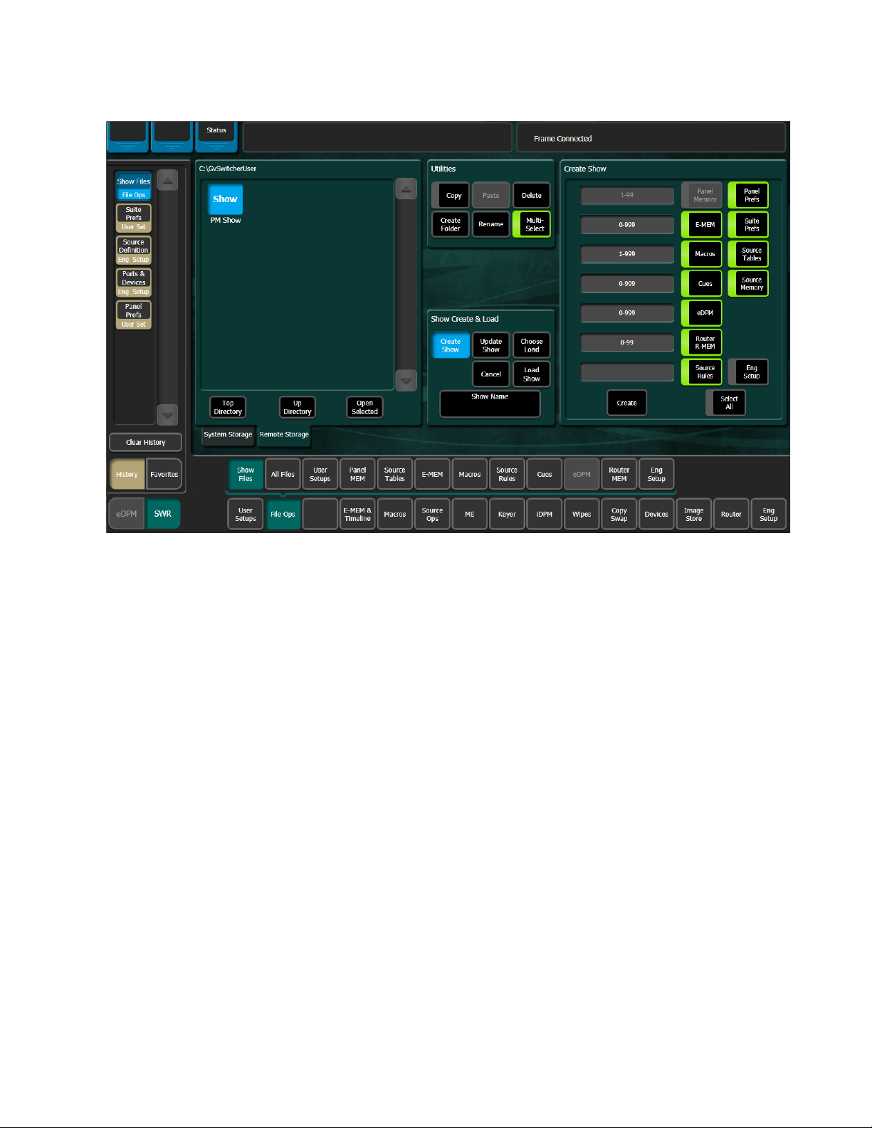
Managing Files Using the Utilities Pane Buttons in the File Ops Menus
Figure 26. File Operations Utilities Pane
Copy/Pasting Files
1. Navigate to the directory containing the file to be copied, using the
Top Directory, Up Directory, and Open Selected (or double-click on the file
icon) buttons.
2. Select the file(s) to be copied (choose the Multi-Select button for multiple
files)
3. Touc h t he Copy button. A new pane with its own scroll bar will appear
to the right.
right-hand pane. Files can only be pasted to the new right-hand pane.
The Delete, Create
pane only, and are inactive during a Copy/Paste operation.
4. Navigate the right-hand pane to the desired directory, using its
navigation buttons.
5. Touc h t he Paste button. A message indicating the file is being copied
will be displayed, and when finished the right-hand pane will close.
Note Use clear naming conventions and logical directory structures when creating
Top, Up, and Open navigation buttons will also appear for the
Folder, and Rename functions apply to the left-hand
folders and renaming files so you can reliably reload the correct versions of
these files when you need them.
KAYENNE K-FRAME — User Manual 55
Page 56

Section 3 — Setting Suite Preferences
Deleting Files
1. Navigate to the directory containing the file(s) to be deleted, using the
Top Directory, Up Directory, and Open Selected (or double-click on the file
icon) buttons.
2. Touch the file icon(s) to highlight it.
3. Touch the Delete button.
Creating a Folder
1. Touch the Create Folder button.
2. Enter the folder name in the pop-up keyboard.
3. Tou ch Enter.
Renaming Files
1. Navigate to the directory containing the file to be renamed, using the
Top Directory, Up Directory, and Open Selected (or double-click on the file
icon) buttons.
2. Touch the file icon to highlight it (only one file can be renamed at a
time).
3. Touch the Rename button.
4. Enter the new file name in the pop-up keyboard.
5. Tou ch Enter.
56 KAYENNE K-FRAME — User Manual
Page 57

GV Switcher File Type Extensions
GV Switcher files are named by the user when saved, and this name
appears below the icon. The extension for each GV Switcher system file
type is listed in
Table 7. GV Switcher System File Extensions
Icon Example File Type Extension
Ta bl e 7.
GV Switcher File Type Extensions
Panel Prefs .GVC
.GVF
.GVJ
Suite Prefs .GVS
.GVZ
Eng Setup .GVE
.GVH
.GVN
E-MEM Reg .GVR
R-MEM Reg .GVY
Panel Memory Reg .PMEM
Cues Reg .GVB
e-DPM Reg .GVI
Image Store .EIF
Macro Reg .GVG
Source Rules .GVL
Show Folders .GVV
Show Files
Show File Buttons
The extension is added to the file automatically when saved, but is not displayed as part of the file name itself. To prevent confusion, do not try to add
an extension to the file name when saving files.
Non-GV Switcher generated file icons show the file name with extension,
and displays the extension letters in the icon.
A Show is a special collection of GV Switcher files that can be managed as
a group. You can create and load a show file that contains all of your
switcher settings or you may want to customize your show by loading
some file types and not others. Both can be accomplished from the Show
Files menu.
Create Show: opens a create show pane. In this pane you enter the name of
the Show (touch the
Show Name data pad), and if you choose, select which
KAYENNE K-FRAME — User Manual 57
Page 58

Section 3 — Setting Suite Preferences
file types and choose a range of registers that will be included in the Show
file.
Load Show: immediately loads all the files in the currently selected show into
the GV Switcher system. This operation will overwrite the existing settings
that are currently being used. While the current work buffer and video
outputs will not be affected, other aspects of system operation (source map
ping, source name displays, available effects, etc.) will change depending
on what files are being loaded.
CAUTION Verify that the Show contains the desired files before loading, especially if the
Choose Load: brings up a pane that allows you to see what files are contained
in the Show, and select which files to load. Buttons for files not present are
grayed out. By default all the files in the Show are selected for load.
Specify the file types and ranges of files you wish to load, then touch the
Load button.
Clear and Replace: removes all files and replaces them so you can limit what
is loaded to what is in the Show file and not a cumulative load/overwrite.
-
system is currently on-air.
Select All: (toggle) button selects or deselects all the available file types.
Touching on a file type button selects or deselects that individual type of
file for saving/loading. Touching the data pads just to the left of the file
type buttons allows you to enter a range of registers, of that type, to include
in the show.
Create: saves the show into the currently selected directory. A pop-up panel
displays the status of each file type as the Show file is created.
Update Show: brings up a pane that allows you to select specific files within
a show to update. Specify the file types and ranges of files you wish to
update, then touch the
Update button. The selected files in the show will be
overwritten with the current GV Switcher settings for those items.
Note A best practice is to set the E-MEM range from 0-999 each time there is an
update, this will ensure that new registers are included (the same practice can
be applied to other file types).
58 KAYENNE K-FRAME — User Manual
Page 59

Create a Show File
1. Tou ch File Ops, Show Files (Figure 27).
Figure 27. Create Show File Operations
Show Files
CAUTION The Eng Setup button is off by default as ports and server IPs are unique so
transferring Show files from one location to another (including suites)
requires planning to prevent interruption.
2. Select the Create Show button in the Show Create & Load pane (bottom-
center).
3. Touch the Show Name data pad, type a name for the Show file, and
touch
4. In the Create Show pane, touch to select/deselect file types, or touch
the
be inactive).
5. Select the register data pad (left of each button) and enter a series or
range of registers to be included in the Show file (the default is all).
Note A best practice is to set the E-MEM range from 0-999 each time there is an
Enter.
Select All button (e-DPM is an option, if not installed the button will
update, this will ensure that new registers are included (the same practice can
be applied to other file types).
KAYENNE K-FRAME — User Manual 59
Page 60

Section 3 — Setting Suite Preferences
6. Touch the Create button in the Create Show pane.
Result: The Show file is created with the selected file types and appears
in the directory.
Load a Show File
All Show files can be loaded or selected Show files using the Show Create
& Load menu pane.
1. Tou ch File Ops, Show Files (Figure 28).
Figure 28. Load Show File Operations
CAUTION The Eng Setup button is off by default as ports and server IPs are unique so
transferring Show files from one location to another (including suites)
requires planning to prevent interruption.
2. Navigate to and touch the Show file you wish to load in the Directory
pane (left side of menu).
3. To load all files saved in a Show file, touch the Load Show button in the
Show Create & Load pane.
60 KAYENNE K-FRAME — User Manual
Page 61

Show Files
4. To only load selected files in a show, touch the Choose Load button to
bring up the Crate Show pane that allows you to see what files are
contained in the Show, and choose which files to load by touching the
File Type buttons.
5. In the Create Show pane, touch to select/deselect file types, or touch
the
Select All button (e-DPM is an option, if not installed the button will
be inactive).
6. Select the register data pad (left of each button) and enter a series or
range of registers to be included in the Show file (the default is all).
Note A best practice is to set the E-MEM range from 0-999 each time there is an
update, this will ensure that new registers are included (the same practice can
be applied to other file types).
7. Touch the Load button in the Create Show pane to load the Show file (not
the
Load Show button as this will load the entire Show file without your
File Type selections).
Load a Show from the Show Load History
Shows that have been loaded, are displayed in the Show Load History pane
on the right side of the Show Files menu. The list of previously loaded
shows are displayed until the
Show Load” reflects the date and time that the top item in history, was
loaded—in the current menu.
1. Select File Ops, Show Files.
2. Select a previously loaded show from the Show Load History scrolling
list on the right.
3. The selected show file is automatically displayed in the left-hand
directory pane.
4. Select the Load Show button.
Clear History button is selected. The “Last
KAYENNE K-FRAME — User Manual 61
Page 62

Section 3 — Setting Suite Preferences
Note A pink highlighted load list item means a full show, otherwise it is a partial
Figure 29. Show Files—Show Load History
show.
Updating a Show File
1. Tou ch File Ops, Show Files (Figure 28).
62 KAYENNE K-FRAME — User Manual
Page 63
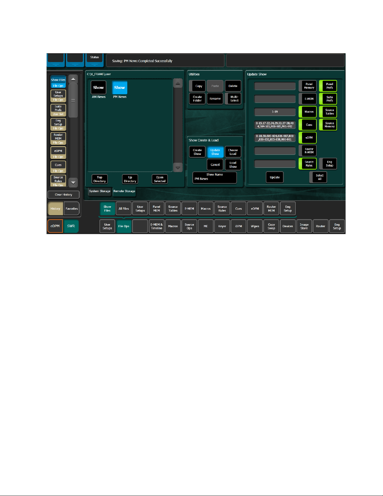
Figure 30. Update Show File Operations
Show Files
CAUTION The Eng Setup button is off by default as ports and server IPs are unique so
transferring Show files from one location to another (including suites)
requires planning to prevent interruption.
2. Navigate to and touch the Show file you wish to update in the Directory
pane (left side of menu).
3. Touc h t he Update Show button in the Show Create & Load pane to bring
up the Create Show pane that allows you to see what files are contained
in the Show, and choose which files to load by touching the File Type
buttons.
4. In the Create Show pane, touch to select/deselect file types, or touch
Select All button (e-DPM is an option, if not installed the button will
the
be inactive).
5. Select the register data pad (left of each button) and enter a series or
range of registers to be included in the Show file (the default is all).
Note A best practice is to set the E-MEM range from 0-999 each time there is an
update, this will ensure that new registers are included (the same practice can
be applied to other file types).
6. Touc h t he Update button in the Create Show pane to update the Show
file.
KAYENNE K-FRAME — User Manual 63
Page 64

Section 3 — Setting Suite Preferences
All File Type and Directory Management
The File Ops, All Files menu is used to quickly sort by using the Sort By Type,
Sort By Name, and Reverse Order (reorders the current sort to ascending or
descending) buttons and manage all files types in the System Storage and
Remote Storage directories. Use the Utilities pane buttons to perform file
operations. The menu is accessed from
Figure 31. All Files Menu
File Ops, All Files (Figure 31).
64 KAYENNE K-FRAME — User Manual
Page 65

Saving Panel Prefs and Suite Prefs Files
Saving Panel Prefs and Suite Prefs Files
1. Access the User Setups menu by touching, File Ops, User Setups.
Figure 32. User Setups Menu
2. Touc h t he Panel Prefs or Suite Prefs button.
3. Navigate to and touch the Show file you wish to update in the Directory
pane (left side of menu) and:
a. Touch a file to select it, or
b. Create a new file by touching the File Name button, typing a name,
and touching
4. In the Load Granularity pane, touch to select/deselect file types, or
touch the
5. Touc h t he Save button in the File Operations pane.
Select All button.
Loading Panel Prefs and Suite Prefs Files
1. Access the User Setups menu by touching, File Ops, User Setups
(Figure 32).
Enter.
KAYENNE K-FRAME — User Manual 65
Page 66
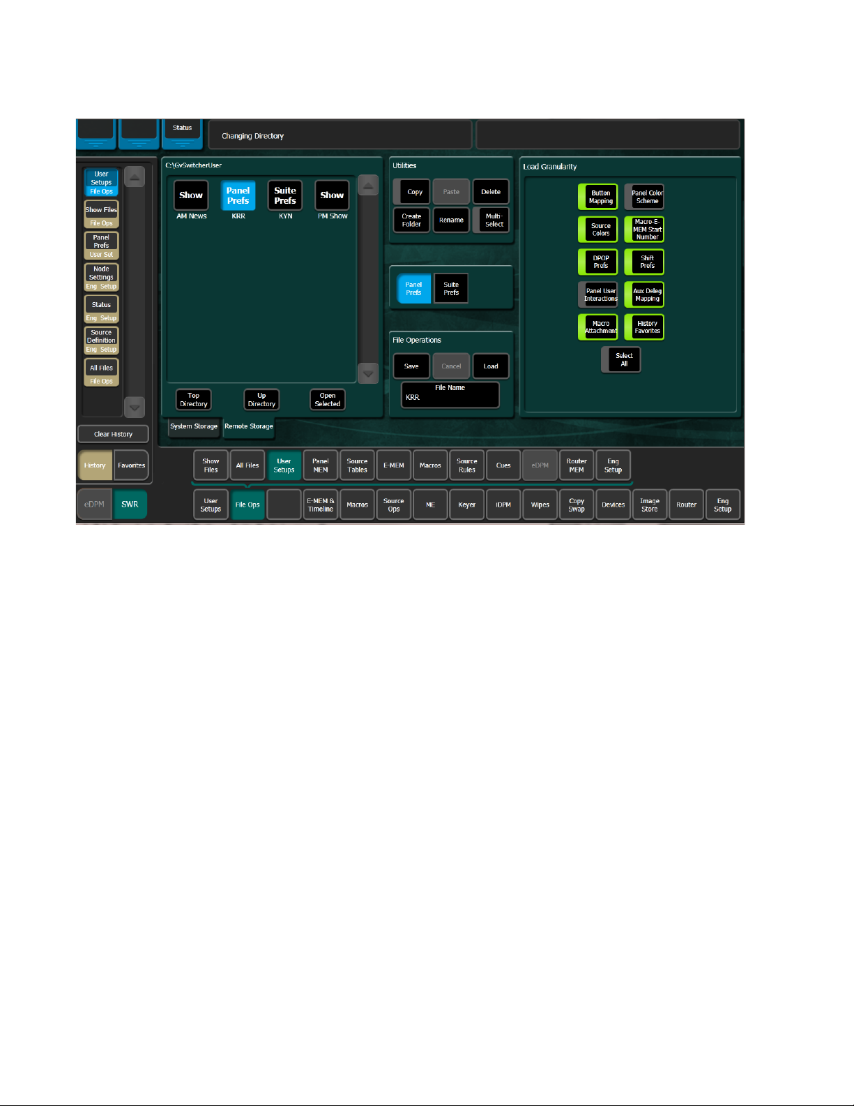
Section 3 — Setting Suite Preferences
Figure 33. User Setups Menu
2. Navigate to and touch the Show file you wish to update in the Directory
pane (left side of menu) and:
a. Touch a file to select it, or
b. Create a new file by touching the File Name button, typing a name,
and touching
3. In the Load Granularity pane, touch to select/deselect file types, or
touch the
4. Touch the Load button.
CAUTION The Load button immediately replaces information the GV Switcher system
Saving Source Tables
1. Access the Source Rules menu by touching, File Ops, Source Tables.
Enter.
Select All button.
is currently using with the selected file information. When configuration files
are loaded, significant changes to GV Switcher system operation are possible.
66 KAYENNE K-FRAME — User Manual
Page 67

Figure 34. Source Tables Menu
Saving Source Tables
2. Select a file by:
a. Navigating to the desired destination directory and touching a file
to select it, or
b. Creating a new file by touching the File Name button, typing a name,
and touching
3. Tou ch Save.
Enter.
KAYENNE K-FRAME — User Manual 67
Page 68

Section 3 — Setting Suite Preferences
Loading Source Tables
1. Access the Source Rules menu by touching, File Ops, Source Tables
(Figure 32).
Figure 35. Source Tables Menu
Register Files
2. Select a file by:
a. Navigating to the desired destination directory and touching a file
to select it, or
b. Creating a new file by touching the File Name button, typing a name,
and touching
3. Tou ch Load.
Register file menus all function similarly and are used to save and load
their corresponding register files. Each menu is accessed by touching,
File Ops, then the menu category: Panel MEM, E-MEM, Macros, Cues, e-DPM, or
Router MEM.
Enter.
68 KAYENNE K-FRAME — User Manual
Page 69

Saving Register Files
The key difference in these menus are the number of registers, for example
the E-MEM menu has 1000 register files while the Macro menu has 999, and
Router MEM has 100, and so on. Keep this in mind when entering registers.
Register files are named by their bank and register number. For example,
the filename for E-MEM register 5 in Bank 2 would appear as EMEM25. File
names consist of the bank and register appended with.GVR. It is important
that these files retain these names, as the number determines which register
will receive the data when files are loaded. In fact, register files saved
locally to the Frame C: drive cannot be renamed. If you try to rename an EMEM file on the Frame C: drive an error message will appear in the
message area. If for some reason an E-MEM file needs to be renamed, copy
it to a local drive and rename it.
Each menu is similar to the other File Ops menus with a file display pane
on the left and the same navigation and action buttons in the center.
Each menu provides the Utilities pane (Copy, Paste, etc.) and the ability to
select all, individual, or a range of register files to be saved or loaded. In
addition, in the File Operations pane, you can enter a starting register
which allows you to save/load a register or range of registers to a different
register or range of registers.
Saving Register Files
The File Ops Memory menus provide controls for saving and loading register files for each area of the switcher.
1. Access the Panel MEM, E-MEM, Macros, Cues, e-DPM, or Router MEM
menu by touching,
File Ops, and then selecting a MEM category.
KAYENNE K-FRAME — User Manual 69
Page 70

Section 3 — Setting Suite Preferences
Figure 36. Source Tables Example Menu
2. Select a file by:
a. Navigating to the desired destination directory and touching a file
to select it, or
b. Creating a new file by touching the File Name button, typing a name,
and touching
3. Touch one of the three Save/Load Register mode buttons (center) and
a. Touch the All button to select all register files, or
b. Touch the Enter Reg(s) button then enter a register or range of
registers in the
c. Touch the Select Reg(s) button then select register files in the file
display panel (touch
4. Tou ch Save.
Result: The register or range of registers is saved to the target directory.
Enter.
Register data pad (right), for example 1-5,10,12, or
Multi-Select button for multiple selections).
70 KAYENNE K-FRAME — User Manual
Page 71
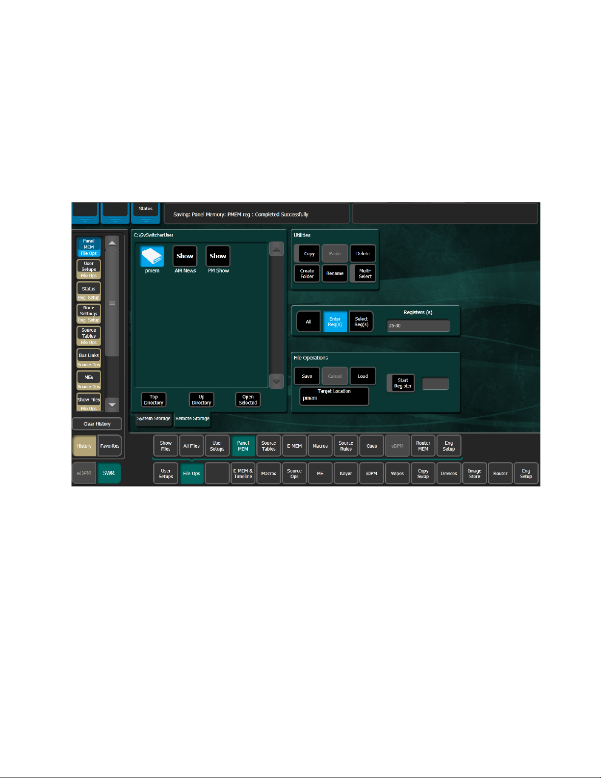
Loading Register Files
The File Ops Memory menus provide controls for saving and loading register files for each area of the switcher.
1. Access the Panel MEM, Source Tables, E-MEM, Macros, Cues, e-DPM,
or Router
category.
Figure 37. Panel MEM Menu—Load Registers
Loading Register Files
MEM menu by touching, File Ops, and then selecting a MEM
2. Select a file by:
a. Navigating to the desired destination directory and touching a file
to select it, or
b. Creating a new file by touching the File Name button, typing a name,
and touching
3. Touch one of the three Save/Load Register mode buttons (center) and
a. Tou ch th e All button to select all register files, or
b. Tou ch th e Enter Reg(s) button then enter a register or range of
registers in the
c. Touc h t he Select Reg(s) button then select register files in the file
display panel (touch
Enter.
Register data pad (right), for example 1-5,10,12, or
Multi-Select button for multiple selections).
KAYENNE K-FRAME — User Manual 71
Page 72

Section 3 — Setting Suite Preferences
4. Tou ch Load.
Result: The register or range of registers are loaded into the GV Switcher.
Loading to a Different Set of Registers
Registers can be loaded with an offset.
1. Navigate to the desired destination directory and/or create a new
folder for the file using the buttons in the File Operations pane.
2. Touch the Enter Reg(s) button then enter a register or range of registers in
the
3. Touch the Start Register (highlights green) button.
4. Enter the number of the first register into which you wish to load the
selected range of registers, then touch
5. Touch the Load button.
Result: The range of registers will be loaded to the specified register
number shown in the
Register data pad (right).
Enter.
Register data pad.
72 KAYENNE K-FRAME — User Manual
Page 73

Saving Source Rules Files
1. Access the Source Rules menu by touching, File Ops, Source Rules
(Figure 32).
Figure 38. Source Rules Menu
Saving Source Rules Files
2. Select a file by:
a. Navigating to the desired destination directory and touching a file
to select it, or
b. Creating a new file by touching the File Name button, typing a name,
and touching
3. Tou ch Save.
Enter.
KAYENNE K-FRAME — User Manual 73
Page 74

Section 3 — Setting Suite Preferences
Loading Source Rules Files
1. Access the Source Rules menu by touching, File Ops, Source Rules
(Figure 32).
Figure 39. Source Rules Menu
2. Select a file by:
a. Navigating to the desired destination directory and touching a file
to select it, or
b. Creating a new file by touching the File Name button, typing a name,
and touching
3. Tou ch Load.
Enter.
74 KAYENNE K-FRAME — User Manual
Page 75

Saving Eng Setup Files
The File Ops, Eng Setup menu is used to save and load engineering setups
information. Only this file format is supported in this menu.
1. The menu is accessed by touching File Ops, Eng Setups (Figure 40).
Figure 40. Eng Setup Save-Load Menu
Saving Eng Setup Files
2. Navigate to the desired destination directory and:
a. Touch a file to select it, or
b. Create a new file by touching the File Name button, typing a name,
and touching
3. In the Load Granularity pane, touch to select/deselect file types, or
touch the
4. Touc h t he Save button.
Select All button.
Enter.
KAYENNE K-FRAME — User Manual 75
Page 76
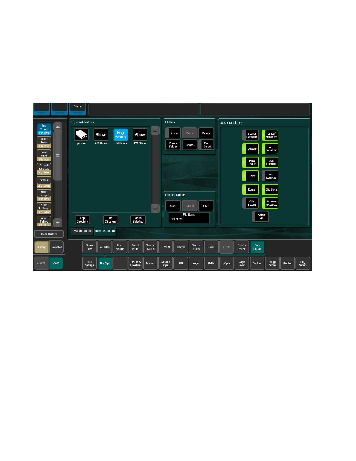
Section 3 — Setting Suite Preferences
Loading Eng Setup Files
The File Ops, Eng Setup menu is used to save and load engineering setups
information. Only this file format is supported in this menu.
1. The menu is accessed by touching File Ops, Eng Setups (Figure 40).
Figure 41. Eng Setup Save-Load Menu
2. Navigate to the desired destination directory and:
a. Touch a file to select it, or
b. Create a new file by touching the File Name button, typing a name,
and touching
3. In the Load Granularity pane, touch to select/deselect file types, or
touch the
CAUTION The Load button immediately replaces information the GV Switcher system
4. Touch the Load button.
Select All button.
is currently using with the selected file information. When configuration files
are loaded, significant changes to GV Switcher system operation are possible.
Enter.
76 KAYENNE K-FRAME — User Manual
Page 77

File Translation From Kayenne
About K-Frame and Kayenne Show Files
When loading a show created on a Kayenne frame system into a K-Frame
system, all the files transfer and the configuration files will set up the
K-Frame switcher for most functionality. However, because the K-Frame
hardware is different from the Kayenne frame, some settings will need to
be changed. These adjustments affect Eng Setups, Panel Prefs, and Suite
Prefs. In addition, while Macros and EMEMs from a Kayenne system will
run, if they include fixed sources they will not produce the correct effect.
Source Patching is one way to quickly resolve that issue.
Loading a Kayenne Show into a K-Frame
Eng Setup Adjustments
File Translation From Kayenne
• The Acquired Resources will not load from Kayenne. You should
update them first, including Acquisition of GPIs if you use them.
• The Frame Operating Mode will need to be set in the Video Settings
menu.
• Fixed Outputs connector settings will need to be updated in the
Outputs menu.
• ClipStore configuration settings will need to be re-entered. in the Clip-
Store Config menu.
• Modular I/O settings may need adjustment in the SetDef MatchDef
menu.
Note K-Frame 6.0 supports 24 PBus devices. The eight Kayenne PBus devices will
map to the first eight K-Frame devices.
Panel Prefs Adjustments
• Image Store and eDPM delegations can now be assigned separate
colors in the Panel Color Scheme menu.
• Source Colors for preview sources will need to be selected again in the
Panel Color Scheme menu.
• All Kayenne Background U1 & U2 functions are translated to the C and
D backgrounds in K-Frame. If you setup U1 and U2 for DPOP in Kayenne, they will transfer to C and D. The U1 and U2 buses are not used
for this in K-Frame.
• Aux Delegate Mapping for the two Image Store and six eDPM inputs
are adjusted in the Aux Delegate Mapping menu.
KAYENNE K-FRAME — User Manual 77
Page 78

Section 3 — Setting Suite Preferences
Suite Prefs Adjustments
• K-Frame has more Image Store channels than Kayenne. The E-MEM
Prefs for Image Store are adjusted in the Suite Prefs/EMEM Prefs/
Image Store menu. They will need to be set to the ME levels they are
used on.
E-MEMs and Macros – Source Patching
K-Frame fixed sources are different from Kayenne, so any Kayenne
EMEMS and Macros using them will not run properly on K-Frame.
One of the quickest ways to adjust for E-MEM and Macro functions is to
Source Patch the K-Frame fixed sources to the source IDs they had on Kay
enne. Tab le 8 on page 79 shows this source patching. For example, source
patch Logical Source 201 to Eng Source M1 A to make that K-Frame fixed
source match Kayenne’s. This allows sources that were selected using
E-MEMs and Macros on the Kayenne frame systems to be selected using
K-Frame E-MEMs and Macros.
-
78 KAYENNE K-FRAME — User Manual
Page 79

File Translation From Kayenne
Table 8. K-Frame Source Mapping for Kayenne Fixed Sources
Logical ID Eng Source Logical ID Eng Source
ME 1
201 M1 A 225 Pg A
202 M1 B 226 Pg B
203 M1 C 227 Pg C
204 M1 D 228 Pg D
205 M1 pA 229 Pg pA
206 M1 pC 230 Pg pC
ME 2 eDPM
207 M2 A 231 eDA
208 M2 B 232 eDAk
209 M2 C 235 eDC
210 M2 D 236 eDCk
211 M2 pA
212 M2 pC 240 Blk
ME 3
213 M3 A 244 Blk Key
214 M3 B 239 Test1
215 M3 C 241 Bg 1
216 M3 D 242 Bg 2
217 M3 pA
218 M3 pC 245 IS 1A
ME 4
219 M4 A 247 IS 3A
220 M4 B 248 IS 4A
221 M4 C 249 IS 5A
222 M4 D 250 IS 6A
223 M4 pA
224 M4 pC
Pgm Pst
Generated Sources
241 Wht
Image Store
246 IS 2A
E-MEM – Enable Definable Levels
Definable levels will need to be re-enabled in some effects. If you are using
definable levels then check to see that the levels are enabled and re-enable
them in effects that use them. The timeline of the definable level will be OK.
Only the enable will need to be modified.
Two Outputs on K-Frame eDPM
The K-Frame eDPM has two outputs. Each K-Frame suite can have an
eDPM if the K-Frame system is licensed for two.
KAYENNE K-FRAME — User Manual 79
Page 80

Section 3 — Setting Suite Preferences
Importing Kalypso Image Store File Types into K-Frame
CAUTION When importing files into Image Store cache, existing files with the same ID
• The still files must be named using the default Kalypso numbering
format (I000000.gvi/.gva, but not greater than I008999.gvi/.gva). If a
Kalypso still has been renamed, change it back to this naming format
using the Kalypso system, or by renaming both the .gva and .gvi files to
matching file names directly in the computer directory.
• Both of the Kalypso still .gvi and .gva file components must be present
for each image.
• Thumbnail .bmp images are not supported (the Kayenne K-Frame
system generates its own thumbnails). Kalypso image .bmp files can be
ignored, and can safely be deleted from the directory to keep them from
appearing on the Image Store Library menu screen.
• Kalypso clip conversion is not supported.
will be overwritten so check if the ID already exists in the cache.
Note Kalypso NTSC Still Store images contain 486 lines, while the Kayenne
K-Frame Image Store supports 487 lines. A Kayenne K-Frame system will
display one black line at the bottom of the image raster of converted Kalypso
NTSC stills.
80 KAYENNE K-FRAME — User Manual
Page 81

Video Mix/Effects
MEs and Keyers
An ME is a subsystem of a video production switcher that can create a composite of two or more pictures. An ME includes multiple source selection
buses and provides transition (mix and wipe) and keying capabilities on
the selected signals.
Keyers are used to insert part of one picture into another to create a composite picture. Keying involves three signals:
• background,
• key cut, used to specify where to cut a hole in the background, and
• key fill, used to fill the hole in the background. The fill can be an
incoming video signal or it can be an internally generated matte.
Section 4
Chroma Key
A separate key cut input signal is not necessarily required for keying. For
example, a self key (also called a video key) uses the same input signal for
both key cut and key fill.
The GV Switcher system supports the following types of keys:
• Linear Key (fixed and adjustable)
• Luminance Key
• Preset Pattern
• Chroma Key (option)
The GV Switcher system also supports self keys and split keys.
The GV Switcher system features the chroma keyers option with powerful
controls. These controls offer subtle adjustments to allow successful keying
of difficult subject matter (fine hair, smoke, translucent objects, etc.), and to
overcome some problems resulting from imperfect chroma key set coloring
KAYENNE K-FRAME — User Manual 81
Page 82

Section 4 — Video Mix/Effects
or lighting. The GV Switcher chroma key also has an Auto Setup feature
that can create an excellent chroma key under most circumstances without
the need for manual adjustment.
The following information provides more detailed instructions on how to
set up a chroma key using the Auto Setup feature and use the manual con
trols in the Keyer menu.
Chroma Key Auto Setup
The first step of setting up most chroma keys is to use Auto Setup. Auto
Setup automates the first steps to achieving a chroma key. Auto Setup per
forms the following:
• Calculates primary suppression Hue and Luminance.
• Sets primary suppression Selectivity and Chroma to defaults.
• Calculates Clip Low, and sets Clip Hi to default.
• Sets all the secondary suppression values to duplicate the primary sup-
-
-
pression values, but turns secondary suppression off.
• Changes Opacity temporarily to 100% to permit an accurate backing
color sample, and then returns it to its original setting.
• Sets Key Position and Size values to default (0).
Two different Auto Setup algorithms are available, one for well designed
and lighted sets (
Reshape on). Depending on individual circumstances, additional manual
(
adjustments may be required after you use Auto Setup.
After an Auto Setup has been initiated, you can cancel it by pressing the
Auto Setup button again, but the chroma key will retain the default settings
imposed.
Reshape off), and the other for more challenging sets
Manual Chroma Key Adjustments
If the Auto Setup of the hue fails to provide a suitable chroma key, additional controls are available in the Keyer menu for fine tuning the key.
Chroma key manual set up consists of choosing the best set of compromises
to provide adequate detail and color fidelity to meet your needs. While
using this menu you need to view the chroma key scene on a monitor. A
vectorscope and waveform monitor can also be very useful when setting
up a chroma key. During set up you need to focus your attention on partic
ular areas of the foreground, background, and/or composite. The areas you
look at will change depending on the individual controls being used. The
FG Only and BG Only menu buttons can be used to remove extraneous picture
information, allowing you to view only those areas of the composite.
-
82 KAYENNE K-FRAME — User Manual
Page 83

Chroma key set up procedures follow a recommended order, as indicated
by the numbered steps displayed on the menu. However, requirements can
vary depending on each individual scene. You may need to go back to
earlier steps and readjust previous settings to optimize the key. Under
standing what the chroma key controls do will help you decide what
adjustments are required for your individual situation.
Access Keyer Menu and Delegate Keyer
On the Menu Panel, touch Keyer, Mode. You can also double press the Chr
button in the Multi-Function area to access this menu. Delegate the keyer
you wish to set up on the left side of the screen, then touch the
Mode button (
Figure 42. Keyer Chroma Menu, Pri Suppress Controls
Figure 42).
Chroma Key
-
Chroma Key
Primary Suppression
Primary suppression is the most critical chroma key parameter, and the
easiest to set. Auto Setup should take care of this, but manual adjustments
can be made if desired. If primary suppression is set wrong, however, it will
be impossible to achieve a good chroma key with the other controls.
KAYENNE K-FRAME — User Manual 83
Page 84

Section 4 — Video Mix/Effects
Primary Suppression should be set while looking at the foreground. Ideally
the backing color will appear as a small dot on the vector scope and a per
fectly flat line on the waveform display, but this never occurs due to set
lighting variations, shadows, etc. This means you will need to pick the best
suppression for the overall look of the key.
You can touch the stage 1 Pri Suppress data pad, if necessary, to activate these
controls (
primary suppression to eliminate the backing color.
Figure 42) and adjust Hue, Selectivity, Chroma, and Luma
• Hue can be set accurately with Auto Setup. Hue should center on the
primary color of the backing area of the foreground scene.
Depending on where
adjusting
Chroma suppression should be preset to 100% and Luma set to 0%.
Hue can then be tuned to remove the backing color.
Selectivity may need to be increased if there are colors in the fore-
•
ground image that are being suppressed.
low as possible without including colors that should not be suppressed. For example, when keying on green, a greenish yellow
shirt might be affected by the suppression. If so, adjust the selectivity high enough to reject that color. Too high a selectivity is one
of the classic causes of a noisy key. If the foreground subject is stationary, consider using a force mask instead of increasing selectivity.
Chroma suppression can be set accurately with Auto Setup. To
•
adjust, increase
dot on the vector scope move toward the center. You want to center
it exactly, so no chroma exists in the backing area. 100% chroma suppression is the correct setting for all chroma keys. At this point, you
will probably see a line through the center of the vector scope. With
increased selectivity, this line will become an arc.
Hue may not make any noticeable change on the scene.
Luma and Chroma primary suppression are set,
Selectivity should be set as
Chroma suppression and observe the backing color
-
Luma suppression adjustments may be necessary if shading is
•
visible in the backing area with
adversely affects the background image. Primary Luma suppression is hardly ever desired when Reshape is on. To adjust, increase
Luma suppression and observe the backing color move toward
black. You want to make the backing color just black. Increasing this
control too much will make the chroma key hard and noisy. When
not enough, highlights will be added to the background. Note that
incomplete luminance suppression is not necessarily bad. The highlights added to the background will match the shading on the
backing wall, adding natural shadows and perhaps eliminating the
need to add artificial shadows.
• All the above adjustments may need to be revisited later.
Another potential artifact of chroma keying is a tinting of the overall foreground subject due to lighting splash from the backing color or lens flare.
Flare Suppression adds a small amount of color to the entire foreground
84 KAYENNE K-FRAME — User Manual
FG Only selected, or if the shading
Page 85

image to cancel the splash or flare. Typically less than 2% of the backing
color is needed to neutralize the flare.
Extra Chroma Key Controls
Additional chroma key controls are available by touching the stage 4 Extra
Controls
individually activated by touching the labeled buttons.
Figure 43. Extra Controls
data pad (Figure 43). Coring, fringe, and shadow controls can be
Chroma Key
Coring replaces any pixels in the luminance signal after primary suppression
that are below the adjustable threshold with black. This eliminates noise
resulting from incomplete suppression. While coring can improve some
keys, it can easily be over done. Coring thresholds much above black will
affect dark grays that are actually part of the foreground subject, making
the chroma key composite look unnatural.
Fringe is used to restore color to the gray portions of the foreground color
resulting from secondary suppression adjustments. This control is only
active when secondary suppression is on.
Shdw provides controls of shadows that fall on the backing. Shadow Clip and
Shadow Gain allow selecting the range of the luminance portion of the fore-
KAYENNE K-FRAME — User Manual 85
Page 86

Section 4 — Video Mix/Effects
Reshape Off
ground that produces a shadow. Shadow Density is an opacity control for the
shadow and adjusts how much shadow is added to the background.
Setting Up a Chroma Key
Using Auto Setup
1. Press one of the Key 1-Key 6 Transition buttons on an ME to delegate the
keyer you wish to use.
2. Choose the selected keyer’s key bus that has the chroma key source and
the chroma key backing color.
3. Select the Chr as the key type in the Multi-Function area (source memory
may automatically select this key type).
4. Choose on the A bus the source that will be used to replace the backing
color of the chroma key source.
5. Go to the Keyer menu (double press the Keyer 1-Keyer 6 button for that
keyer in the Keyer Transition area) and make sure
keyer you are using (
Figure 44. Keyer Menu, Chroma Key Reshape Off
Figure 44).
Reshape is off for the
86 KAYENNE K-FRAME — User Manual
Page 87

Setting Up a Chroma Key
6. Press the Auto Setup button in the Multi-Function area. Preview for that
ME will now display the chroma key source with a superimposed
cursor. The cursor actually represents a box of 16 x 16 pixels.
7. Use the joystick to position the cursor on the backing color. Select a
darker area, if one exists, to optimize the backing color suppression.
8. Press the button on top of the joystick. The chroma key will be set up
automatically using the average of the colors selected by the cursor box.
Because
9. If this chroma key is acceptable, you are done. If set, lighting, or other
conditions prevent the result from being acceptable, you need to decide
whether to adjust the chroma key manually or use Auto Setup with
Reshape.
• Manual adjustment permits retention of fine edge detail (see the
• Auto Setup with Reshape produces a chroma key with harder
Reshape was off, fine edges of the key will be preserved.
Switcher Concepts Manual for more information). In particular, if
there are problems with translucent areas (hair, smoke) secondary
suppression controls can be useful.
edges, but accommodates wider set variations (see below).
Reshaping a Chroma Key Using Auto Setup
If the set is lit unevenly or has other problems, Reshape is available to help
solve the problem. A better alternative, if time permits, is to adjust the
lighting on the set to even out the backing color. This may improve the key
so that Reshape is not needed.
1. If you decide you must use Reshape, follow the Auto Setup procedure
described above, but in
turn it on (its green indicator will illuminate). After selecting the
backing color area and touching the top button on the joystick, the
chroma key will be set up with coarser values better able to handle set
variations.
2. If this chroma key is acceptable, you are done. If you are still not
satisfied, you can fine tune the chroma key using manual adjustments.
Step 5 touch Reshape on in the Keyer menu to
Adjusting Chroma Key Controls
The purpose in adjusting Clip Hi and Clip Low is to cause the proper hole to
be cut in the background. All areas of the backing color should be full back
ground while all areas of the foreground should make the background
completely invisible. The easiest way to do this is to observe the key signal
while making your adjustments.
-
KAYENNE K-FRAME — User Manual 87
Page 88

Section 4 — Video Mix/Effects
The smaller the difference between Clip Hi and Clip Lo, the higher the keyer
gain. High gain amplifies noise present in the transition between trans
parent and opaque. The correct setting is with Clip Hi and Clip Lo set to just
barely achieve opacity and transparency, respectively
1. Touch the stage 2 Key Controls data pad to activate these controls. You can
2. Select Show Key in the Keyer menu (Figure 45) and look at the ME
Figure 45. Key Controls
-
.
now manually adjust keyer clipping controls.
preview output on a picture and waveform monitor.
3. Adjust Clip Hi so that all areas of the foreground objects are white. If
Clip Hi is set too low (too far clockwise), much of the translucent areas
will be forced to be fully opaque, hardening the key and darkening the
transition area between background and foreground.
4. Clip Low can be set accurately with Auto Setup. Adjust Clip Low so that all
areas of the backing color are black. If
counter-clockwise), translucent areas will be forced fully translucent,
hardening the key.
Note When adjusting clip levels, remember that areas on the edge of the fore-
ground subject should show as shades of gray. Gray indicates areas of trans-
lucency, which is desirable in chroma keying.
Clip Lo is set too high (too far
88 KAYENNE K-FRAME — User Manual
Page 89

5. Check the final results with Show Key off and the chroma keyer in normal
mode (
hard, noisy key.
6. If the chroma key now looks good, you are done. If dark edges are
present, there may be too much primary
Clip Low may be set improperly. If adjusting these parameters fails to
solve the problem, you should consider activating the Reshape feature.
FG Only turned off). Note that incorrect adjustments can create a
Reshaping Chroma Key
Reshape is useful when shading variations exists in the backing color. A
better alternative, if time permits, is to adjust the lighting on the set to even
out the backing color. This may improve the key so that Reshape is not
needed. Reshape helps with backing color suppression at the expense of a
harder looking key with more noticeable edge artifacts.A drawback of
Reshape is loss of detail in the keyed edge. For example, smoke and hair in
the foreground will probably be lost.
Setting Up a Chroma Key
Luma suppression or Clip Hi or
1. Touc h t he Reshape button to activate this feature.
2. Set primary Luma suppression to 0.
3. You can now readjust the Clip Hi and Clip Low controls if necessary to fine
tune the key as described above.
4. When Reshape is on, key resizing and positioning also become available
to clean up the key edges.
• Size narrows the key signal and can remove much of the blue or
green edge on the foreground subject.
Position moves the key signal left and right, and can be used to
•
reduce a color edge along only one side of the foreground.
Applying Chroma Key Secondary Color Suppression
Secondary color suppression is intended to improve the color of translucent areas (e.g., glass or smoke) or fine detail near the edge of a foreground
subject (e.g., hair). These areas can be take on some of the backing color.
Much less secondary suppression will be needed than is used for primary
suppression, because the foreground color is only partially corrupted by
the backing color. Because there is a mixture of backing color and fore
ground color, the secondary suppression Hue and the direction (Angle)
will be different from primary suppression. Primary suppression removes
the backing color, while secondary suppression corrects the color in trans
lucent areas.
-
-
KAYENNE K-FRAME — User Manual 89
Page 90

Section 4 — Video Mix/Effects
Note If Reshape has been applied, it is unlikely enough edge detail will remain to
1. Touch the stage 3 Sec Suppress data pad and then touch the
Figure 46. Sec Suppress Controls
use secondary color suppression.
Secondary Suppress button to activate this feature (Figure 46).
2. Adjust secondary suppression Hue and Selectivity so that the translucent
area is affected, but opaque areas of the foreground are not. The final
hue will lie somewhere between the backing color (primary
suppression hue) and the uncorrupted foreground color.
• When making this adjustment, it is helpful to turn the secondary
Chroma Suppression to maximum, and the secondary Suppression Angle
to produce an unnatural color in the affected area. This makes the
changes to secondary suppression more obvious.
• Selectivity should be kept as wide as possible. You should only
narrow selectivity (increase its value) if you cannot avoid changing
opaque areas of the foreground.
3. Adjust the secondary Angle so that changing secondary Chroma
suppression moves the color in the desired direction. You are trying to
match the color of the translucent areas to an opaque (uncorrupted)
area of the foreground subject.
90 KAYENNE K-FRAME — User Manual
Page 91

4. Decrease secondary Chroma suppression for the best match between
corrupted (translucent) and uncorrupted (opaque) areas. Interaction
between secondary suppression Angle and Chroma suppression may
require repeating these adjustments.
5. Increase secondary Luma suppression to balance lightness of the
translucent and opaque areas.
6. Repeat secondary suppression Angle, Chroma suppression and Luma
suppression for best results.
Generating Background Mattes
Background matte generators create colors and washes. These can be used,
for example, as the backgrounds for keys.
Background mattes cannot use the wipe pattern generators available to
keyer and wipe mattes, and cannot use Utility video as a wipe source.
Instead background mattes employ a simple dedicated wipe generator that
creates a single, straight line.
Generating Background Mattes
Background matte control is available from the Control Panel (Multi-Function area, Matt button in the Home menu) and from the Keyer, Matte menu,
which provides additional background parameter controls.
1. Go to the Mattes menu by pressing Keyer, Mattes.
2. Touc h t he BKGD button.
3. If not already selected, touch the Base Color data pad of the desired
Background (1 or 2). Use the top three soft knobs to adjust
Base Saturation, and Base Brightness of the base fill color (Figure 47).
Base Hue,
KAYENNE K-FRAME — User Manual 91
Page 92
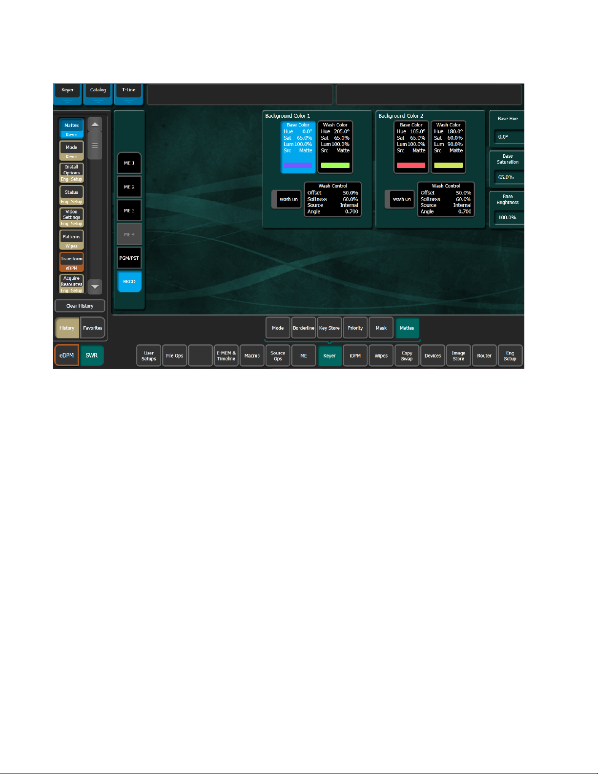
Section 4 — Video Mix/Effects
Figure 47. Matte Menu, Base Color Selected
Splitting a Key
4. Touch the Wash On button at the bottom so its indicator illuminates to
create a wash matte.
5. Touch t he Wash Control data pad to bring up Offset, Softness, and Rotate soft
knob controls. If necessary, use the
wash edge visible on the screen. You can also turn on the
and then adjust the angle of the edge using the
6. Touch the Wash Color data pad to delegate the soft knobs on the right to
adjust
Because all background matte parameters are keyframeable, you can build
effects with constantly changing backgrounds using multiple keyframes.
Sometimes you may wish to use the key cut signal of one source with the
key fill or video signal of another source. For example, you may have a
Character Generator creating matte filled characters, but wish to use a dif
ferent signal to fill the characters. A split key is used to accomplish this.
Wash Hue, Wash Saturation, and Wash Brightness of the wash fill color.
Offset and Softness knobs to make the
Rotate button,
Rotate soft knob.
-
Note On GV Switcher systems, the source select buses by default tally the key fill
signal.
92 KAYENNE K-FRAME — User Manual
Page 93

Splitting a Key
A split key can be created three different ways:
• Configure a source in the Eng Setup/Source Destination menu that
uses different video for cut than for fill. That split key will initially be
used whenever that engineering source is selected. See the K-Frame
Installation and Service Manual for more information.
• Setup a key patch (an implicit split key). This split key is used whenever
that logical source is selected, and adds operational flexibility. See Patch
a Key Input from One Source to a Different Source Using Patch Key on
page 45 for more information.
• Setup an explicit split key using the Source Ops menu. This split key is
used only at the time is has been set. Selecting a different source, then
returning to that formerly split source removes the split key.
To create an explicit split key:
1. Touch Source Ops, MEs (Figure 48).
Figure 48. Split Key—Source Ops, MEs Menu
2. Touch an ME button (left).
3. Touch the Cut signal data pad for the Keyer you wish to split
(highlights blue).
KAYENNE K-FRAME — User Manual 93
Page 94

Section 4 — Video Mix/Effects
4. Select a source from the scrolling Source List (right) and touch that
source.
The ME Status display in the Transition area shows the source names of
any key cut signals.
Note Split Key will be shown in the Multi-Function area display.
Setting Keyer Priority
The GV Switcher system has six keyers per ME so complex stacking is possible. Keys can be placed between other keys, using key priority.
Note You can also apply the following to the Keyer Secondary Priority Stack when
1. Tou ch Keyer, Priority (Figure 49).
an ME is in Split Mode.
Figure 49. Keyer Priority Menu, Current Stack Selected
2. If not already set up, turn on the desired keys and arrange them so they
overlap, observing the Program monitor. This will make the changes in
key priority visible. For demonstration purposes, you can use four
preset pattern keys.
94 KAYENNE K-FRAME — User Manual
Page 95

3. Select the keyer you wish to move in the stack in the Current column,
then use the
place the key in the desired location. The key priority order changes
immediately, as a cut.
Top, Move Up, Move Down, and Bottom buttons on the left to
Transitioning Between Different Keyer Priorities
Key priority transitions use a Current priority stack and a Next priority
stack. The transition occurs between the two stacks.
Note You can also apply the following to the Keyer Secondary Priority Stack when
an ME is in Split Mode.
1. Press the Key Prior Transition Element button in the Transition area
(button row under status display, far left function button).
2. If not already set up, turn on the desired keys and arrange them so they
overlap, observing the Program monitor. This will make the changes in
key priority visible. For demonstration purposes, you can use four
preset pattern keys.
Setting Keyer Priority
3. Delegate that ME for preview in the Preview button group on the
System Bar. This shows the end result of the transition (the Next
priority).
4. Go to the Keyer, Priority menu in the Menu Panel by pressing Keyer,
Priority.
5. The current stack in the menu is automatically set to what is currently
being output. You can change the Current priority stacking order if
desired, as described on
page 95.
KAYENNE K-FRAME — User Manual 95
Page 96

Section 4 — Video Mix/Effects
6. Set up the Next priority stacking order, selecting the keyers in the Next
Figure 50. Keyer Priority Menu, Next Stack Selected
column and then using the
(
Figure 50). The new stack will be visible on the preview monitor.
Top, Move Up, Move Down, and Bottom buttons
Key Store
7. Select the type of transition, using the Mix, Wipe 1, or Wipe 2 buttons in
the Transition area. If you selected a wipe, go to the Wipes menu by
double pressing one of the
any modifiers to be used with the wipe.
8. Move the lever arm or press the Auto button in the Transition area to
perform the key priority transition. The transition is shown on the
Program monitor.
Each keyer can store two frames of memory; each frame containing both
Keyer Video (fill) and Key (cut), that together create the Key Store.
Each Key Store can save the use of other switcher resources. For example
instead of using an Image Store channel or another keyer, you could store
a station ID or a replay graphic (still) for a sports show in a Key Store and
switch the image within the keyer.
Wipe buttons, and then select the pattern and
96 KAYENNE K-FRAME — User Manual
Page 97

Key Store
In the Keyer, Key Store menu (Figure 51), each Store has two frames, Frame
Store 1 and Frame Store 2. Each can ‘Grab’, ‘Store’, and ‘Use’ a still image
for a key source. So in addition to Live video, you have up to two fill/cut
images that can be interchanged on any full keyer source.
Figure 51. Key Store Menu
Show Key button—Shows the cut signal for the selected Key Store source.
Push to Preview button—Shows the current Key Store image on Preview.
The fill and cut from Live, and Frame Store 1 and Frame Store 2 pages can
be used in any combination, for example you can use the fill from Keyer
Video Source, Frame Store 1 with the cut from Keyer Cutout Source, Frame
Store 2. You can even use the Live video from the Keyer Video Source and
the cut from Keyer Cutout Source, Frame Store
On power cycle or reboot, Key Stores will have to be reloaded with the
correct video. They default to black keyed with black which will not show
up on a monitor.
Key Store is E-MEMable and keyframeable.
1.
KAYENNE K-FRAME — User Manual 97
Page 98

Section 4 — Video Mix/Effects
Grabbing a Key Store Image
The keyer settings are defined in the Eng Setup, Source Definition menu
where for example you can set a key to a Linear or Shaped Video. You will
need to define these parameters when creating a Key Store, if not defined
the key will be full raster white.
You can ‘Grab’ both a video and key frame simultaneously by touching
either the
page, or you can touch a
Frame Stores (
Once you grab fill and key images in Key Store, they are available for the
selected key source:
1. Tou ch Keyer, Keystore.
Figure 52. Key Store Menu
Grab V&K 1 or Grab V&K 2 button, located below each Frame Store
Figure 52).
Grab button for any of the four Video/Cutout
2. Touch a keyer with which you want to use a Key Store (Figure 52, left).
3. Touch either the Use Live V&K, Use FS 1 V&K, or Use FS2 V&K to select the
Video and Key source image (
a. Touch the Keyer Video Source you want as fill.
Figure 52), or
b. Touch the Keyer Cutout Source you want as the key cut.
98 KAYENNE K-FRAME — User Manual
Page 99

Setting a Pattern Mix
You can combine the complex wipe pattern generators (P1 and P2), to create
a wide variety of customized wipes.
1. Double press the Wipe 1 button in the Transition area. This selects Wipe 1
as the next transition type, and also opens the Wipes menu with
PRI
Wipe 1 delegated for control.
2. Select the P1 pattern to be used by touching the Wipe Pattern button
between the
one of the displayed patterns in the Pattern tab on the right.
Figure 53. Wipes, Patterns Menu
Setting a Pattern Mix
Pattern Mix and Generator/Border data pads, and then selecting
3. Select the Pattern Mix data pad, this switches the Pattern tab on the right
to the other generator; in this case P2 (to select the base wipe pattern
again, touch the Wipe Pattern button as in Step 2).
4. Touc h t he Mix data pad located below the Pattern tab. Additional
control buttons will appear at the bottom of the menu.
5. Delegate that ME for preview in the System Bar.
6. Press the Tran s PVW button in the Transition area, and move the lever
arm part way. This will display the P1 pattern on preview.
KAYENNE K-FRAME — User Manual 99
Page 100

Section 4 — Video Mix/Effects
7. Touch the delegation button in the Pri Wipe 1 column to delegate the
menu to control the Pri Wipe
8. Touch the Pattern Mix button so its indicator illuminates. The preview
monitor will now show the combined Mix
9. You can select the type of pattern mix with the Mix type buttons (Mix,
NAM +, NAM –). The NAM buttons are used for And or Or pattern mixing.
10. You can also adjust the amount each wipe pattern contributes to the mix
with the
the other pattern contributes only 25% to the final pattern.
About Source Memory
Source Memory is a K-Frame system feature that can be used to retain
keyer settings for each source on each keyer bus. Source Memory permits
the operator to, for example, hot cut from one source to another on that
keyer bus and automatically restore different settings learned for each
keyer source.
1 pattern generator.
1 and Mix 2 pattern.
Ratio control. At 50%, each pattern contributes equally. At 25%,
Source Memory settings for a keyer source are only applied when that
source is selected on that keyer bus. Selecting on that keyer bus a different
source that does not have learned Source Memory will restore the previous
keyer settings.
Source Memory keying settings include:
• Keyer Mode settings, including Preset Pattern and Chroma
• Keyer Mask settings
• Keyer and Wipes Mattes settings
• ME Video Proc settings (Keyer sources only)
• ME RGB Color Correct (Keyer sources only
• Wipes settings (Keyer sources only)
Source Memory settings are explicitly learned and deleted, using the Source
Memory
The following are NOT affected by Source Memory:
• Split keys
• Keyer Borderline settings
button.
• Keystore settings
• Background sources
• Aux sources
100 KAYENNE K-FRAME — User Manual
 Loading...