

GRASS VALLEY KAYENNE 2.0 - RELEASE NOTES 10-2010, KAYENNE 2.0 - RELEASE NOTES, KAYENNE Release Note
Page 1
KAYENNE
VIDEO PRODUCTION CENTER
Release Notes
Software Version 2.0
071868702
OCTOBER 2010
Page 2

Affiliate with the N.V. KEMA in The Netherlands
CERTIFICATE
Certificate Number: 510040.001
The Quality System of:
Thomson Inc, and its worLdwide Grass Valley division affiliates DBA
GRASS VALLEY
Headquarters
400 Providence Mine Rd
Nevada City, CA 95959
United States
15655 SW Greystone Ct.
Beaverton, OR 97006
United States
10 Presidential Way
Suite 300
Woburn, MA 01801
United States
Kapittelweg 10
4827 HG Breda
The Nederlands
7140 Baymeadows Way
Ste 101
Jacksonville, FL 32256
United States
2300 So. Decker Lake Blvd.
Salt Lake City, UT 84119
United States
Rue du Clos Courtel
CS 31719
35517 Cesson-Sevigné Cedex
France
1 rue de l’Hautil
Z.I. des Boutries BP 150
78702 Conflans-Sainte
Honorine Cedex
France
Technopole Brest-Iroise
Site de la Pointe du Diable
CS 73808
29238 Brest Cedex 3
France
40 Rue de Bray
2 Rue des Landelles
35510 Cesson Sevigné
France
Spinnereistrasse 5
CH-5300 Turgi
Switzerland
Brunnenweg 9
D-64331 Weiterstadt
Germany
Carl-Benz-Strasse 6-8
67105 Schifferstadt
Germany
Including its implementation, meets the requirements of the standard:
ISO 9001:2008
Scope:
The design, manufacture and support of video and audio hardware and software products and
related systems
.
This Certificate is valid until: June 14, 2012
This Certificate is valid as of: June 14, 2009
Certified for the first time: June 14, 2000
H. Pierre Sallé
President
KEMA-Registered Quality
The method of operation for quality certification is defined in the KEMA General Terms
And Conditions For Quality And Environmental Management Systems Certifications.
Integral publication of this certificate is allowed.
KEMA-Registered Quality, Inc.
4377 County Line Road
Chalfont, PA 18914
Ph: (215)997-4519
Fax: (215)997-3809
CRT 001 073004
Accredited By:
ANAB
Page 3

KAYENNE
VIDEO PRODUCTION CENTER
Release Notes
Software Version 2.0
071868702
OCTOBER 2010
Page 4
Contacting Grass Valley
International
Support Centers
Local Support
Centers
(available
during normal
business hours)
France
24 x 7
Australia and New Zealand: +61 1300 721 495 Central/South America: +55 11 5509 3443
Middle East: +971 4 299 64 40 Near East and Africa: +800 8080 2020 or +33 1 48 25 20 20
Europe
+800 8080 2020 or +33 1 48 25 20 20
Hong Kong, Taiwan, Korea, Macau: +852 2531 3058 Indian Subcontinent: +91 22 24933476
Asia
Southeast Asia/Malaysia: +603 7805 3884 Southeast Asia/Singapore: +65 6379 1313
China: +861 0660 159 450 Japan: +81 3 5484 6868
Belarus, Russia, Tadzikistan, Ukraine, Uzbekistan: +7 095 2580924 225 Switzerland: +41 1 487 80 02
S. Europe/Italy-Roma: +39 06 87 20 35 28 -Milan: +39 02 48 41 46 58 S. Europe/Spain: +34 91 512 03 50
Benelux/Belgium: +32 (0) 2 334 90 30 Benelux/Netherlands: +31 (0) 35 62 38 42 1 N. Europe: +45 45 96 88 70
Germany, Austria, Eastern Europe: +49 6150 104 444 UK, Ireland, Israel: +44 118 923 0499
Copyright © Grass Valley, Inc. All rights reserved.
This product may be covered by one or more U.S. and foreign patents.
United States/Canada
24 x 7
+1 800 547 8949 or +1 530 478 4148
Grass Valley Web Site
The www.grassvalley.com web site offers the following:
Online User Documentation — Current versions of product catalogs, brochures,
data sheets, ordering guides, planning guides, manuals, and release notes
in .pdf format can be downloaded.
FAQ Database — Solutions to problems and troubleshooting efforts can be
found by searching our Frequently Asked Questions (FAQ) database.
Software Downloads — Download software updates, drivers, and patches.
4 KAYENNE — Release Notes
Page 5

Contents
Kayenne Release Notes . . . . . . . . . . . . . . . . . . . . . . . . . . . . . . . . . . . . . . . . . . . . . . . . . . 9
Contents
Introduction . . . . . . . . . . . . . . . . . . . . . . . . . . . . . . . . . . . . . . . . . . . . . . . . . . . . . . . . . . . 9
Changes in Release 2.0 . . . . . . . . . . . . . . . . . . . . . . . . . . . . . . . . . . . . . . . . . . . . . . . . 9
New in Release 2.0 . . . . . . . . . . . . . . . . . . . . . . . . . . . . . . . . . . . . . . . . . . . . . . . . . . 9
Improved in Release 2.0 . . . . . . . . . . . . . . . . . . . . . . . . . . . . . . . . . . . . . . . . . . . . 10
Limitations in Release 2.0. . . . . . . . . . . . . . . . . . . . . . . . . . . . . . . . . . . . . . . . . . . . . 10
2.0 Upgrade Effects Existing E-MEMs: Bus Linking and eDPM Timelines . . . 10
Bus Linking and E-MEM Effects . . . . . . . . . . . . . . . . . . . . . . . . . . . . . . . . . . . . . 10
eDPM Effects . . . . . . . . . . . . . . . . . . . . . . . . . . . . . . . . . . . . . . . . . . . . . . . . . . . . . 10
ClipStore (Image Store Clips) . . . . . . . . . . . . . . . . . . . . . . . . . . . . . . . . . . . . . . . . . . . 12
Summit/Solo Software Version . . . . . . . . . . . . . . . . . . . . . . . . . . . . . . . . . . . . . . . 12
System Cabling . . . . . . . . . . . . . . . . . . . . . . . . . . . . . . . . . . . . . . . . . . . . . . . . . . . . . 13
Overview. . . . . . . . . . . . . . . . . . . . . . . . . . . . . . . . . . . . . . . . . . . . . . . . . . . . . . . . . 13
Basic Configuration. . . . . . . . . . . . . . . . . . . . . . . . . . . . . . . . . . . . . . . . . . . . . . . . . . 16
Summit Preparation. . . . . . . . . . . . . . . . . . . . . . . . . . . . . . . . . . . . . . . . . . . . . . . . 17
Kayenne System Preparation . . . . . . . . . . . . . . . . . . . . . . . . . . . . . . . . . . . . . . . . 17
Kayenne Configuration. . . . . . . . . . . . . . . . . . . . . . . . . . . . . . . . . . . . . . . . . . . . . 18
ClipStore Config Menu . . . . . . . . . . . . . . . . . . . . . . . . . . . . . . . . . . . . . . . . . . . . . 24
ClipStore as an External Device. . . . . . . . . . . . . . . . . . . . . . . . . . . . . . . . . . . . . . 26
Kayenne Control Panel Operation . . . . . . . . . . . . . . . . . . . . . . . . . . . . . . . . . . . . . 26
ClipStore Menu Operations . . . . . . . . . . . . . . . . . . . . . . . . . . . . . . . . . . . . . . . . . . . 27
Clip Replay . . . . . . . . . . . . . . . . . . . . . . . . . . . . . . . . . . . . . . . . . . . . . . . . . . . . . . . 27
Replay with E-MEMs . . . . . . . . . . . . . . . . . . . . . . . . . . . . . . . . . . . . . . . . . . . . . . 31
Recording Clips . . . . . . . . . . . . . . . . . . . . . . . . . . . . . . . . . . . . . . . . . . . . . . . . . . . 32
Editing Clips . . . . . . . . . . . . . . . . . . . . . . . . . . . . . . . . . . . . . . . . . . . . . . . . . . . . . . 35
File Operations . . . . . . . . . . . . . . . . . . . . . . . . . . . . . . . . . . . . . . . . . . . . . . . . . . . . 48
Changes to the Stills Menu. . . . . . . . . . . . . . . . . . . . . . . . . . . . . . . . . . . . . . . . . . 50
Key Chaining . . . . . . . . . . . . . . . . . . . . . . . . . . . . . . . . . . . . . . . . . . . . . . . . . . . . . . . . . 52
Creating Chains . . . . . . . . . . . . . . . . . . . . . . . . . . . . . . . . . . . . . . . . . . . . . . . . . . . . . 52
Using Key Cut/Auto Buttons . . . . . . . . . . . . . . . . . . . . . . . . . . . . . . . . . . . . . . . 53
Key Chaining on a Single ME . . . . . . . . . . . . . . . . . . . . . . . . . . . . . . . . . . . . . . . 54
Key Chaining Across MEs . . . . . . . . . . . . . . . . . . . . . . . . . . . . . . . . . . . . . . . . . . . . 55
Multiple Bus Linking . . . . . . . . . . . . . . . . . . . . . . . . . . . . . . . . . . . . . . . . . . . . . . . . . . 57
Configuring Source Substitution Tables . . . . . . . . . . . . . . . . . . . . . . . . . . . . . . . . 58
Source Table File Operations . . . . . . . . . . . . . . . . . . . . . . . . . . . . . . . . . . . . . . . . . . 60
Linking Multiple Busses. . . . . . . . . . . . . . . . . . . . . . . . . . . . . . . . . . . . . . . . . . . . . . 61
Parallel Links . . . . . . . . . . . . . . . . . . . . . . . . . . . . . . . . . . . . . . . . . . . . . . . . . . . . . 62
Cascading Bus Links . . . . . . . . . . . . . . . . . . . . . . . . . . . . . . . . . . . . . . . . . . . . . . . 63
Corner Pinning . . . . . . . . . . . . . . . . . . . . . . . . . . . . . . . . . . . . . . . . . . . . . . . . . . . . . . . 65
Corner Pinning and Cropping. . . . . . . . . . . . . . . . . . . . . . . . . . . . . . . . . . . . . . . . . 66
Corner Pinning Menu . . . . . . . . . . . . . . . . . . . . . . . . . . . . . . . . . . . . . . . . . . . . . . . . 67
Corner Pinning with the Multi-Function Module . . . . . . . . . . . . . . . . . . . . . . . . 71
eDPM Enhancements . . . . . . . . . . . . . . . . . . . . . . . . . . . . . . . . . . . . . . . . . . . . . . . . . . 74
eDPM Partitioning. . . . . . . . . . . . . . . . . . . . . . . . . . . . . . . . . . . . . . . . . . . . . . . . . . . 74
eDPM Definable Sub-levels . . . . . . . . . . . . . . . . . . . . . . . . . . . . . . . . . . . . . . . . . . . 75
Device Control Module Enhancements . . . . . . . . . . . . . . . . . . . . . . . . . . . . . . . . . . . 77
Q-MEM . . . . . . . . . . . . . . . . . . . . . . . . . . . . . . . . . . . . . . . . . . . . . . . . . . . . . . . . . . . . 77
Learning a Q-MEM Register with a Single Device. . . . . . . . . . . . . . . . . . . . . . . . 78
KAYENNE — Release Notes 5
Page 6

Contents
Learning a Q-MEM Register with Multiple Devices. . . . . . . . . . . . . . . . . . . . . . 78
Learning Devices with Letter Buttons . . . . . . . . . . . . . . . . . . . . . . . . . . . . . . . . 78
Learning Additional Devices. . . . . . . . . . . . . . . . . . . . . . . . . . . . . . . . . . . . . . . . 79
Learning Only Device Associations into a Register . . . . . . . . . . . . . . . . . . . . . 80
Learning Clips for Devices without Affecting Letter Button Associations . 80
Cues and Gangs. . . . . . . . . . . . . . . . . . . . . . . . . . . . . . . . . . . . . . . . . . . . . . . . . . . 80
Status Display . . . . . . . . . . . . . . . . . . . . . . . . . . . . . . . . . . . . . . . . . . . . . . . . . . . . . . 81
Gangs . . . . . . . . . . . . . . . . . . . . . . . . . . . . . . . . . . . . . . . . . . . . . . . . . . . . . . . . . . . . . 81
Ganging Devices Associated with Lettered Buttons . . . . . . . . . . . . . . . . . . . . 82
Ganging Additional Devices . . . . . . . . . . . . . . . . . . . . . . . . . . . . . . . . . . . . . . . . 82
Control Panel Enhancements . . . . . . . . . . . . . . . . . . . . . . . . . . . . . . . . . . . . . . . . . . . 83
Copy Swap Menus . . . . . . . . . . . . . . . . . . . . . . . . . . . . . . . . . . . . . . . . . . . . . . . . . . . . 84
Copy Swap ME Menu . . . . . . . . . . . . . . . . . . . . . . . . . . . . . . . . . . . . . . . . . . . . . . . 85
Copy Swap Wipes Menu . . . . . . . . . . . . . . . . . . . . . . . . . . . . . . . . . . . . . . . . . . . . . 86
Wipe Generator Buttons in the To Pane . . . . . . . . . . . . . . . . . . . . . . . . . . . . . . 86
Copying Transition and Keyer Wipes Directly . . . . . . . . . . . . . . . . . . . . . . . . 87
Copying Between Transition and Key Wipes. . . . . . . . . . . . . . . . . . . . . . . . . . 88
Copying with eDPM. . . . . . . . . . . . . . . . . . . . . . . . . . . . . . . . . . . . . . . . . . . . . . . 88
Copy Swap Mattes Menu . . . . . . . . . . . . . . . . . . . . . . . . . . . . . . . . . . . . . . . . . . . . 89
Copy Swap Keyer Menu . . . . . . . . . . . . . . . . . . . . . . . . . . . . . . . . . . . . . . . . . . . . . 90
Copy Swap Source Memory Menu . . . . . . . . . . . . . . . . . . . . . . . . . . . . . . . . . . . . 91
Copy Swap Macro Menu. . . . . . . . . . . . . . . . . . . . . . . . . . . . . . . . . . . . . . . . . . . . . 93
Copy Swap Timeline Menu. . . . . . . . . . . . . . . . . . . . . . . . . . . . . . . . . . . . . . . . . . . 94
Copy Swap and the Multi-Function Module . . . . . . . . . . . . . . . . . . . . . . . . . . . . 96
SetDef MatchDef. . . . . . . . . . . . . . . . . . . . . . . . . . . . . . . . . . . . . . . . . . . . . . . . . . . . . . 97
Source Ops, SetDef MatchDef Menu . . . . . . . . . . . . . . . . . . . . . . . . . . . . . . . . . . . 97
SetDef Output Conversion. . . . . . . . . . . . . . . . . . . . . . . . . . . . . . . . . . . . . . . . . . 98
MatchDef Input Conversion . . . . . . . . . . . . . . . . . . . . . . . . . . . . . . . . . . . . . . . . 99
E-MEM Control of SetDef MatchDef . . . . . . . . . . . . . . . . . . . . . . . . . . . . . . . . . . 100
SetDef . . . . . . . . . . . . . . . . . . . . . . . . . . . . . . . . . . . . . . . . . . . . . . . . . . . . . . . . . . 101
MatchDef . . . . . . . . . . . . . . . . . . . . . . . . . . . . . . . . . . . . . . . . . . . . . . . . . . . . . . . 102
E-MEM of Key Priority Transitions. . . . . . . . . . . . . . . . . . . . . . . . . . . . . . . . . . . . . 104
Key Store Enhancements. . . . . . . . . . . . . . . . . . . . . . . . . . . . . . . . . . . . . . . . . . . . . . 104
Key Store Operations . . . . . . . . . . . . . . . . . . . . . . . . . . . . . . . . . . . . . . . . . . . . . . . 104
Grabbing and Using a Key Store Image . . . . . . . . . . . . . . . . . . . . . . . . . . . . . . . 105
Macros Attached to Buttons without Colors . . . . . . . . . . . . . . . . . . . . . . . . . . . . . 106
Satellite Panel Installation . . . . . . . . . . . . . . . . . . . . . . . . . . . . . . . . . . . . . . . . . . . . . 106
Single Module Satellite Panel . . . . . . . . . . . . . . . . . . . . . . . . . . . . . . . . . . . . . . . . 107
Double Module Satellite Panel . . . . . . . . . . . . . . . . . . . . . . . . . . . . . . . . . . . . . . . 107
Satellite Panel Cabling . . . . . . . . . . . . . . . . . . . . . . . . . . . . . . . . . . . . . . . . . . . . . . 108
PCU Cabling . . . . . . . . . . . . . . . . . . . . . . . . . . . . . . . . . . . . . . . . . . . . . . . . . . . . 108
Internal Cabling. . . . . . . . . . . . . . . . . . . . . . . . . . . . . . . . . . . . . . . . . . . . . . . . . . 108
Setting the Summit/Solo IP Address . . . . . . . . . . . . . . . . . . . . . . . . . . . . . . . . . . . 109
Remote Desktop Connection. . . . . . . . . . . . . . . . . . . . . . . . . . . . . . . . . . . . . . . . . 109
Changing the Summit/Solo IP Address . . . . . . . . . . . . . . . . . . . . . . . . . . . . . . . 109
Kayenne Software Update . . . . . . . . . . . . . . . . . . . . . . . . . . . . . . . . . . . . . . . . . . . . 114
Introduction. . . . . . . . . . . . . . . . . . . . . . . . . . . . . . . . . . . . . . . . . . . . . . . . . . . . . . . 114
Materials Required . . . . . . . . . . . . . . . . . . . . . . . . . . . . . . . . . . . . . . . . . . . . . . . 114
Software Update Procedure . . . . . . . . . . . . . . . . . . . . . . . . . . . . . . . . . . . . . . . . .
Backup Current Configuration and Effects Files . . . . . . . . . . . . . . . . . . . . . . 115
Deploy Kayenne Update Package Files and Installer . . . . . . . . . . . . . . . . . . 115
Kayenne Installer Program Description . . . . . . . . . . . . . . . . . . . . . . . . . . . . . 119
System Update (Video Processor Frame & Control Panels). . . . . . . . . . . . . 120
Kayenne Menu Panel Application Installation/Update. . . . . . . . . . . . . . . . 122
114
6 KAYENNE — Release Notes
Page 7

Clear NV RAM for Control Panel and Frame . . . . . . . . . . . . . . . . . . . . . . . . . 127
Calibrate the Lever Arm and Joystick. . . . . . . . . . . . . . . . . . . . . . . . . . . . . . . . 127
Update Additional Kayenne Menu Panels or PCs . . . . . . . . . . . . . . . . . . . . . 128
First Time Kayenne Menu on PC Installation . . . . . . . . . . . . . . . . . . . . . . . . . 128
NetConfig and Newton Configurator Installation . . . . . . . . . . . . . . . . . . . . . 129
Macro Editor Installation . . . . . . . . . . . . . . . . . . . . . . . . . . . . . . . . . . . . . . . . . . 129
Check Software Versions . . . . . . . . . . . . . . . . . . . . . . . . . . . . . . . . . . . . . . . . . . 129
Confirm System Operation. . . . . . . . . . . . . . . . . . . . . . . . . . . . . . . . . . . . . . . . . 130
Backup New Configuration and Effects Files . . . . . . . . . . . . . . . . . . . . . . . . . 130
Other Kayenne Systems Software Update. . . . . . . . . . . . . . . . . . . . . . . . . . . . . . 130
Individual Kayenne System Component Update. . . . . . . . . . . . . . . . . . . . . . . . 130
Removing Kayenne Software . . . . . . . . . . . . . . . . . . . . . . . . . . . . . . . . . . . . . . . . 131
Kayenne Menu Panel Application Removal . . . . . . . . . . . . . . . . . . . . . . . . . . 131
Kayenne Deployment Tool Files Removal. . . . . . . . . . . . . . . . . . . . . . . . . . . . 131
Removing Using the Windows OS . . . . . . . . . . . . . . . . . . . . . . . . . . . . . . . . . . 132
Kayenne System IP Addresses . . . . . . . . . . . . . . . . . . . . . . . . . . . . . . . . . . . . . . . . . 133
Default IP Addresses. . . . . . . . . . . . . . . . . . . . . . . . . . . . . . . . . . . . . . . . . . . . . . . . 133
New Single Control Surface Kayenne Systems. . . . . . . . . . . . . . . . . . . . . . . . . . 133
Multiple Control Surfaces and Suites. . . . . . . . . . . . . . . . . . . . . . . . . . . . . . . . . . 134
Contents
KAYENNE — Release Notes 7
Page 8

Contents
8 KAYENNE — Release Notes
Page 9

Version 2.0
Kayenne Release Notes
Introduction
This document describes installation and other information specific to
Kayenne Video Production Center Release 2.0 software. See
Kayenne system update instructions.
Changes in Release 2.0
OCTOBER 2010
page 114 for
New in Release 2.0
• ClipStore (see page 12)
• Key Chaining (see page 52)
• Multiple Bus Linking (see page 57)
• Corner Pinning (see page 65)
• Copy Swap Menus (see page 84)
• Timeline Copy (see page 94)
• Bank Buttons on Local and Master E-MEM Modules (see page 83)
• Source OLED Enhancements (see page 83)
•Outline mode
• Line wrapping is now supported
• Panel Saver Timer (see page 83)
• Kayenne Menu on PC can be resized (click and drag from corner)
KAYENNE — Release Notes 9
Page 10

Ver sio n 2. 0
Limitations in Release 2.0
Improved in Release 2.0
• eDPM Enhancements (see page 74)
• Device Control Module Enhancements (see page 77)
• Control Panel Enhancements (see page 83)
• SetDef MatchDef (see page 97)
• E-MEM Control of SetDef MatchDef (see page 100)
• E-MEM of Key Priority Transitions (see page 104)
• Key Store Enhancements and Operations (see page 104)
• Macro Attachments (see page 106)
• Satellite Panel Installation Instructions (see page 106)
This Kayenne software release does not support the following features:
• Editor Interface control of a 5th ME, Keyers 5/6, and E-MEM registers
above 100.
2.0 Upgrade Effects Existing E-MEMs: Bus Linking and eDPM Timelines
Some E-MEM effects created using software versions earlier than Kayenne
2.0 will need to be modified as a result of the upgrade:
Bus Linking and E-MEM Effects
In earlier versions of Kayenne software, bus linking was a configuration
setting. In version 2.0, bus linking is now keyframable which provides
greater flexibility and the capability to change links dynamically during a
show. Due to this change, bus links created in older versions of software are
no longer valid in version 2.0 and should be recreated and learned into
E-MEM registers.
eDPM Effects
The following changes will effect the operation of current shows when
upgraded.
10 KAYENNE — Release Notes
Page 11

Introduction
Timeline Modifications
In Kayenne 2.0, eDPM levels of Master E-MEM have their own keyframes
and no longer project the timeline from the eDPM registers. Timelines
imported from version 1.5 software are converted to have a single Key
frame on the eDPM level of Master E-MEM, which will recall the correct
eDPM effect register that corresponds to your existing E-MEM. The fol
lowing are the steps to modify the timeline on the eDPM level to run the
effect from the Master E-MEM:
1. Recall the E-MEM register.
2. Go to E-MEM edit mode and select the end.
3. Disable all Master E-MEM levels except eDPM.
4. Press Modify (this will add a Keyframe to the DPM level at the point of
the run cursor position).
Note The timeline just modified by the above process will be the length of the
overall run time of the selected Master E-MEM level. The actual Master
E-MEM timeline for the eDPM level only needs to be as long as the total
runtime of the eDPM effect (it can be longer, but not less). If the timeline on
the eDPM level needs to be longer than the Master E-MEM effect duration,
position the run cursor on the first keyframe of the eDPM level (disabling all
levels but eDPM) and modify the Keyframe Duration to accommodate the
maximum runtime of the eDPM effect.
-
-
Partition Modifications
The eDPM partition sub-level has moved from Master E-MEM PART to the
eDPM Primary level. Some eDPM effects will have to be modified if they
need partitions:
1. Recall the eDPM effect that has Picture Combiner or partition
information included.
2. In the eDPM mode, Picture, Combiner menu, select the correct eDPM
settings and modify the effect for eDPM Primary.
KAYENNE — Release Notes 11
Page 12

Ver sio n 2. 0
ClipStore (Image Store Clips)
The ClipStore is being introduced with Kayenne 2.0. By seamlessly integrating the K2 Summit/Solo technology into Image Store, you can now
record and play clips with audio. The Summit provides four Video/Key
channels while the Solo provides two.
• The ClipStore is supplied to record and playback with AVC-Intra 100
compression format. Clips imported in DVCPRO HD, DVCPRO 25/50,
DV, and MPEG-2 will play natively.
• The ClipStore supports embedded audio only. The AES inputs and
outputs are not used.
The ClipStore is completely configured and controlled from the Kayenne
menu and control panel. There is no need to use the built-in AppCenter
Elite software. In fact, if changes are made to the ClipStore using App
Center, they will be overwritten by the switcher the next time it sends a configuration to the ClipStore.
This highly integrated solution provides several powerful features,
including:
-
• Fast access to clips and folders,
• Large storage capacity,
• Non-volatile memory—no loss of images due to power failure,
• Clip control from the Kayenne Menu Panel and clip stack control from
the Kayenne Control Panel,
• ClipStore device controls (including macros and cues) are E-MEMable,
and
• Make sub-clips from clips and build composite clips with audio.
Summit/Solo Software Version
Version 7.2.7.1403 is the current version of the AppCenter Elite software for
the ClipStore server, as of the release of this manual. The latest version of
the server software is available on the Kayenne Software Download site.
CAUTION Do not use AppCenter Elite software for ClipStore from the Summit/Solo
server website as it may not be compatible.
For more information about installing and updating AppCenter Elite software, see the Summit/Solo manuals.
12 KAYENNE — Release Notes
Page 13
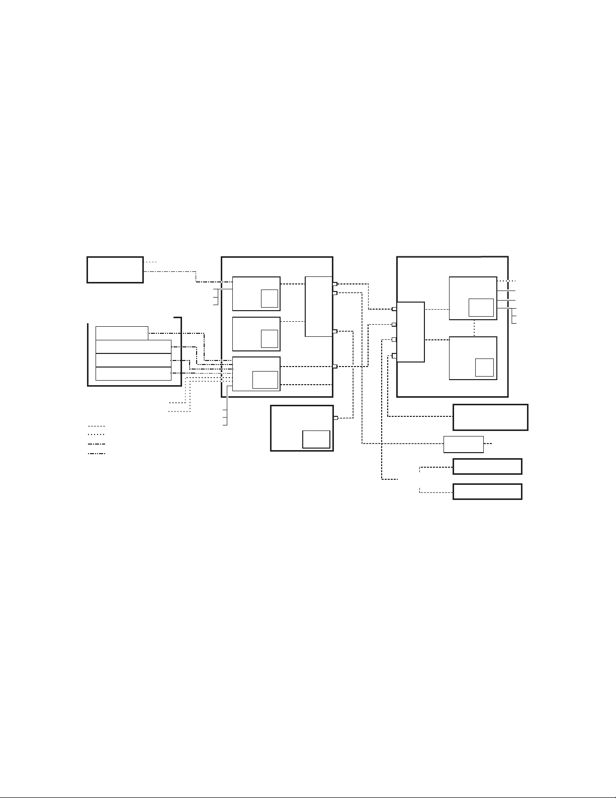
System Cabling
8623266_39_r2
Technical
Director’s
Laptop
CD-ROM
Drive
Disable Internet or
Wireless Connections
Isolate Kayenne System
from External Network
Ethernet
Serial Control
Custom Multi-Pin (Menu, 15m / 50ft max length)
Custom Multi-Pin (Panel, 15m / 50ft max length)
Maintenance Only (board front edge)
*
Internal
Control
Kayenne Video Processor
Frame
Video
Processor
CPU
Compact
Flash
Image
Store
CPU
RAM
Only
Ehternet Switch
1
2
3
4
5
6
7
8
Panel Main LAN
Panel Aux LAN
(not used)
Ehternet Switch
1
2
3
4
5
6
7
8
Kayenne PCU
Menu
CPU
Hard
Disk
Menu
CPU
(option)
Hard
Disk
Panel
CPU
Compact
Flash
Menu Panel
Kayenne Control Panel
Remote Aux Panel
Local Aux Stripe
ME Stripe
ME Stripe
ME Stripe
(Up to 8 Stripe Connections)
USB
RS-422/485
Facility LAN
Switch
Ethernet
Router
Remote Aux Panel
Clip Store
(Image Store Clips)
USB (2)*
Keyboard, VGA*
RS-232*
RS-422/485 (8)
GPI In/Out
Tally
Keyboard, VGA*
RS-232*
USB (2)*
USB (4)
RS-232*
USB (2)*
Keyboard, VGA*
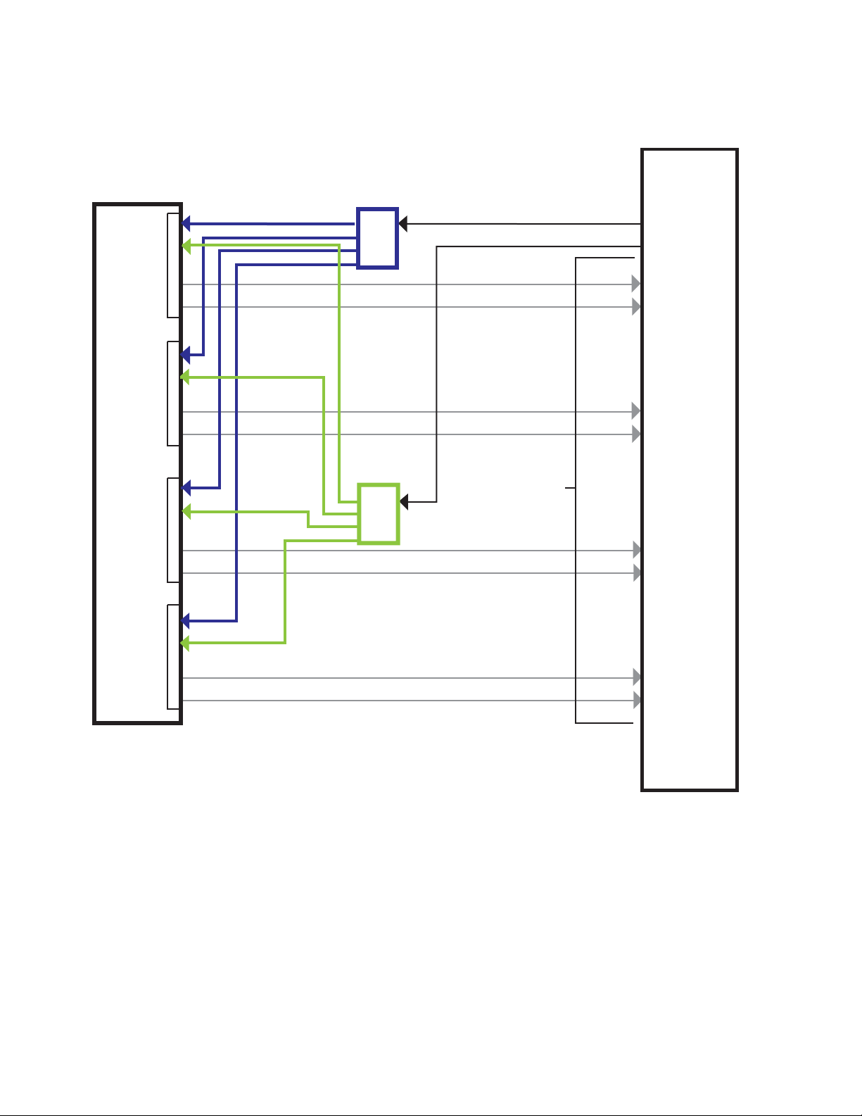
Overview
The Kayenne system uses an Ethernet connection for communications with
ClipStore (K2 Summit/Solo,
Kayenne Frame to the bottom left (of the four) 100BT/1000BT Ethernet
ports on the Summit/Solo backplane.
Note For a detailed cabling description, see the K2 Summit/Solo manuals included
Figure 1. Kayenne System Communications Overview
ClipStore (Image Store Clips)
Figure 1). Connect an Ethernet cable from the
in the packaging.
KAYENNE — Release Notes 13
Video Cabling
The ClipStore channels on the server backplane are labeled C1-C4
(Channel
The Solo backplane is not labeled, Channel 1 is on the left and Channel 2 is
on the right when facing the backplane.
ClipStore requires SDI connections for both video and key— two connections In/Out per channel (C1 in Figure 2) for recording and playback. For
1 through Channel 4 on the Summit) from left to right (Figure 2).
Page 14
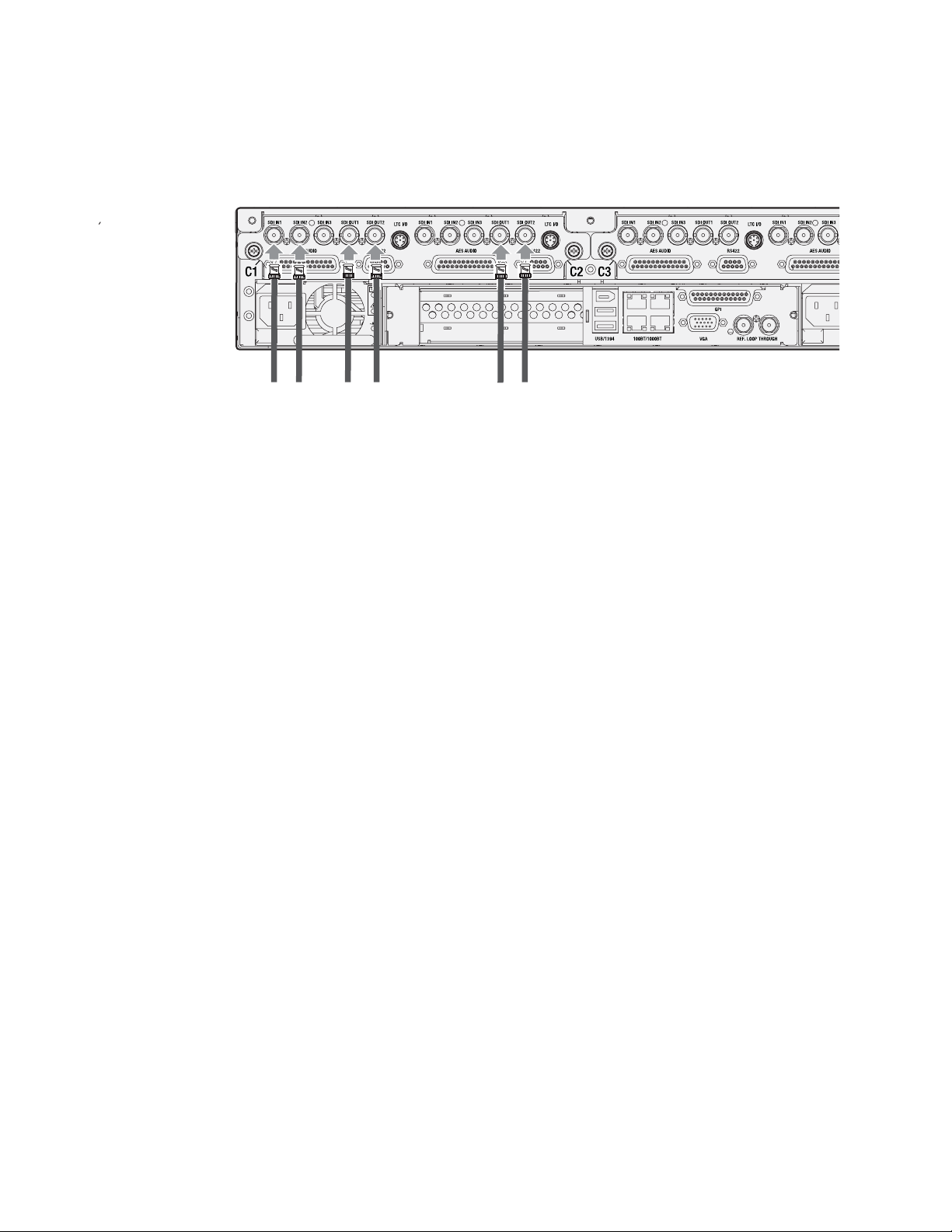
Ver sio n 2. 0
Video/Key
In
(Record/Play)
Video/Key
Out
Video/Key
Out
(Play Only)
playback only, two SDI connections to Out 1 and Out 2 are all that is
required per channel (C2 in
Figure 2. ClipStore Backplane Connections
Figure 2).
14 KAYENNE — Release Notes
Page 15

ClipStore (Image Store Clips)
Channel 2
Channel 3
Channel 4
Channel 1
Kayenne
Video Processing
Frame
C1 SDI IN 2
C1 SDI IN 1
C1 SDI OUT 2
C1 SDI OUT 1
C2 SDI IN 2
C2 SDI IN 1
C2 SDI OUT 2
C2 SDI OUT 1
C3 SDI IN 2
C3 SDI IN 1
C3 SDI OUT 2
C3 SDI OUT 1
C4 SDI IN 2
C4 SDI IN 1
C4 SDI OUT 2
C4 SDI OUT 1
ClipStore
(4 Channel Summit)
8623266_94
The ClipStore server (4-channel Summit/2-Channel Solo) can be connected
directly to the frame (
Figure 3). It is also possible to connect to the ClipStore
directly from a router and not use any switcher outputs.
Figure 3. ClipStore Direct Connection
Odd numbered outputs are used for fill and even are used for cut. The first
output assigned to a ClipStore channel must be an odd numbered output.
Also, DAs (Distribution Amplifiers) can be used to dis tribute Kayenne Aux
Bus output. The example in
Figure 4 shows DAs being used for both the
Video and Key Aux Bus outputs from the frame.
KAYENNE — Release Notes 15
Page 16
Ver sio n 2. 0
Channel 2
Channel 3
Channel 4
Channel 1
Kayenne
Video
Processing
Frame
Aux Bus Out/Key to DA (even)
Aux Bus Out/Video to DA (odd)
ClipStore
(Summit)
Aux Bus
Pair Out
DA
DA
Video/Key
Channels In
Figure 4. ClipStore Connection Using Distribution Amplifiers
Basic Configuration
ClipStore basic configuration includes preparing the Summit/Solo and
Kayenne systems through licensing, IP addressing, software installation,
cabling, and Kayenne menu configurations.
16 KAYENNE — Release Notes
Page 17

Summit Preparation
Setting the IP Address
The ClipStore Summit/Solo server is shipped with the following defaults:
• IP Address: 192.168.0.180
• Mask: 255.255.255.0
• Gateway: 192.168.0.1
• WINS: disabled (0.0.0.0)
• DNS: disabled (0.0.0.0)
You can temporarily change the default settings using Netconfig (see the
NetConfig Network Configuration Application Instruction Manual at
www.grassvalley.com).
To set a new IP Address at the ClipStore (Summit/Solo) server, see Setting
the Summit/Solo IP Address on page 109.
ClipStore (Image Store Clips)
The NetConfig Network Configuration Tool is installed as part of the
Kayenne software.
Note Make note of the ClipStore IP Address, it will be used later to enable Clip-
Stores as external devices later in the Kayenne configuration process.
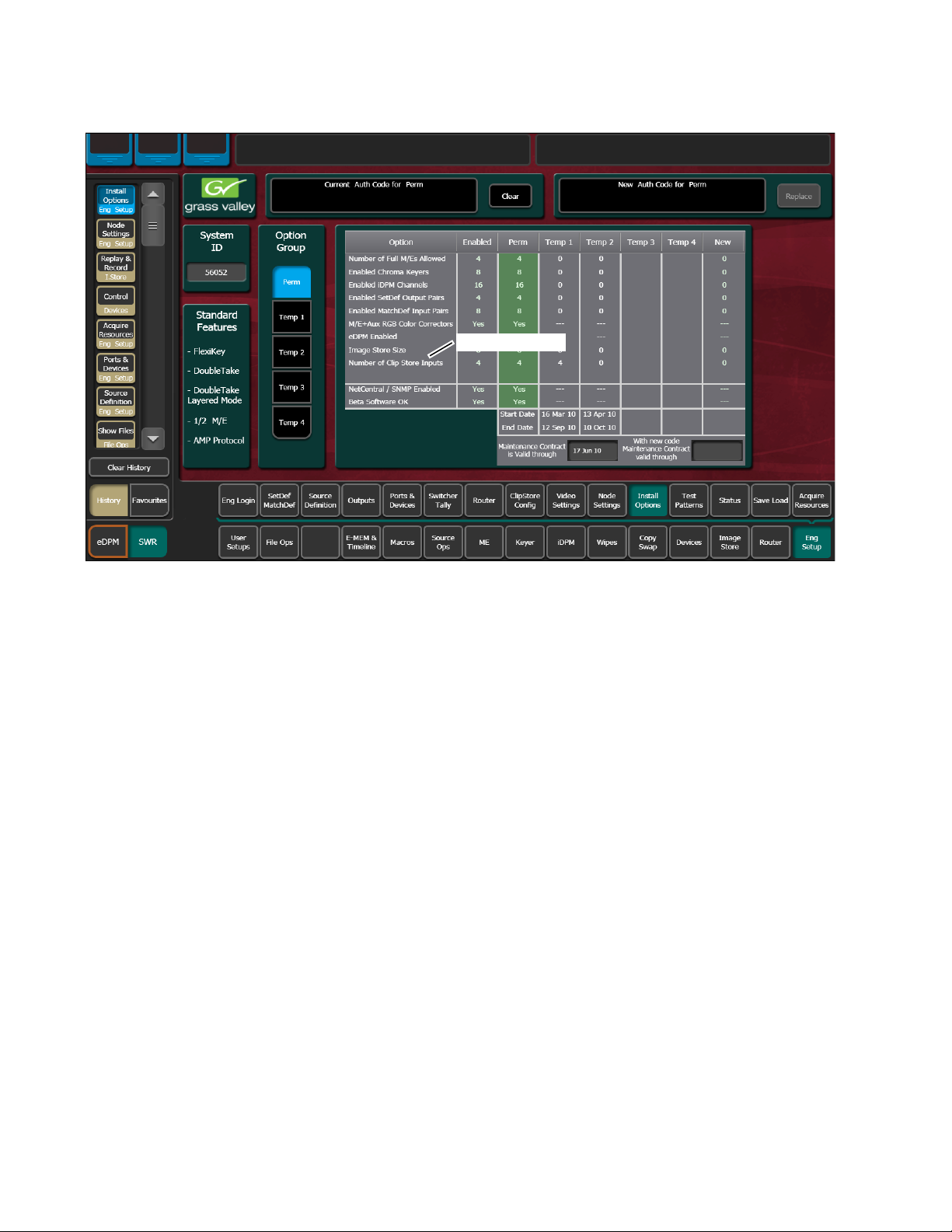
Kayenne System Preparation
Install Kayenne Software Version 2.0 or Later
Verify that the Kayenne software is version 2.0 or later. For information
about upgrading Kayenne software, see
page 114.
Install the ClipStore license (Figure 5). The following are the Kayenne ClipStore options (see the Kayenne Installation and Service Manual for more about
licensing):
• KAYN-CLPS-2CH-PAK (2-Channel Solo Server Platform)
• KAYN-CLPS-4CH-PAK (4-Channel Summit Server Platform)
Kayenne Software Update on
KAYENNE — Release Notes 17
Page 18
Ver sio n 2. 0
ClipStore Licenses
Figure 5. ClipStore License
Kayenne Configuration
Configuring ClipStore as a Node
ClipStore must be configured as a node in the Eng Setup, Node Settings
menu before the Kayenne system can communicate with the Summit/Solo
ClipStore server.
1. Verify there is a valid network connection.
2. Go to the Node Settings menu by touching Eng Setup, Node Settings, Frame
Suite Nodes & ID
3. Input a valid IP address for the ClipStore server by touching the
ClipStore IP Address data pad, typing the address, and touching Enter
Figure 6).
(
4. Tou ch t he Enable button (Figure 6).
The Enable button allows communication between the Kayenne and
the ClipStore server and highlights green indicating a proper connec
tion. Red will show no connection and yellow shows that some channels are connected. For both red and yellow indications, ensure that
channels are in AMP mode and available for remote control. Other
troubleshooting may be required.
(Figure 6).
-
18 KAYENNE — Release Notes
Page 19
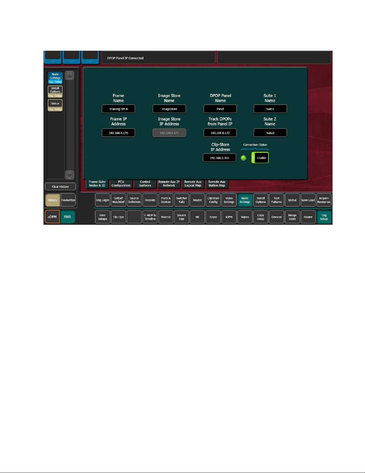
Figure 6. ClipStore Node Settings
ClipStore (Image Store Clips)
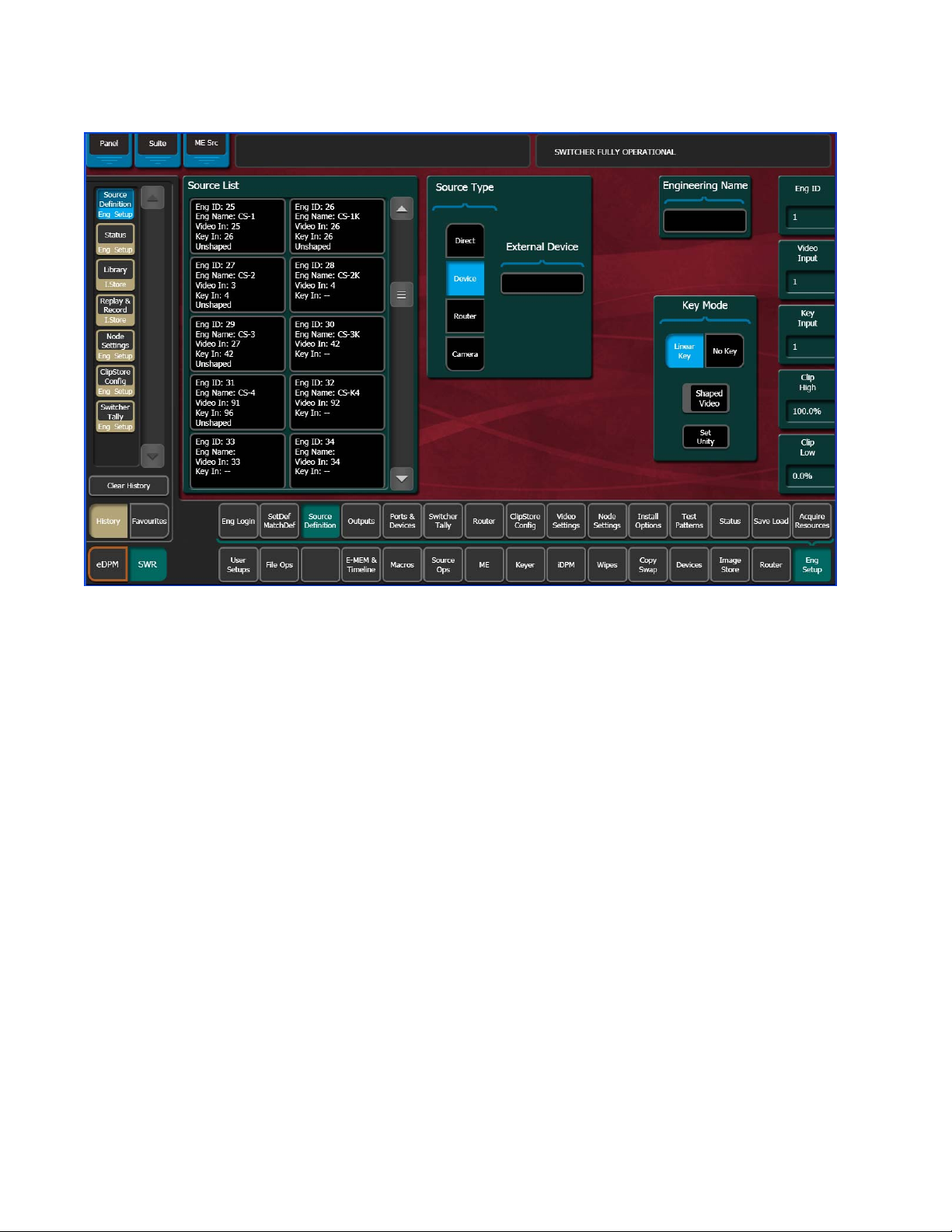
Configuring Source Definitions
To configure source definitions for ClipStore return outputs, choose a
source, a source type, an input, and in the case of a key, an Engineering
Name for the source if desired.
The following example demonstrates the configuration of a Summit with
four ClipStore channels. In this example the physical BNC connections
from the ClipStore to the Kayenne Frame are Inputs 25-32.
ClipStore can record Video only, Key only, or Video/Key clips. To do this,
both a video and a key for the video must be configured for each ClipStore
channel.
To configure a source for as a ClipStore Video input:
1. Go to the Eng Setup, Source Definition menu (Figure 7).
KAYENNE — Release Notes 19
Page 20
Ver sio n 2. 0
Figure 7. ClipStore Source Definition
2. From the Source List, touch a source (Figure 7).
3. Use the default video input (Video In:) or change it using the Video Input
data pad.
4. Touch the Linear Key button to select it.
5. Use the Key Input data pad (or soft knob) to select the source number of
the Key source you will use for the ClipStore channel.
6. Configure the Source Type:
a. To uch the Device mode button in the Source Type pane (Figure 8).
b. To uch the External Device data pad, the External Device List is
displayed (Figure 8).
20 KAYENNE — Release Notes
Page 21
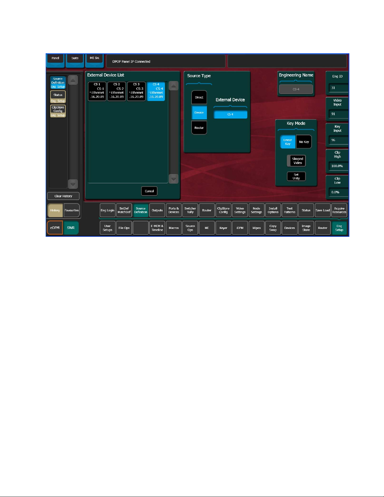
Figure 8. ClipStore External Device List
ClipStore (Image Store Clips)
c. Touch a CS channel to select it (Figure 8).
The External Device List closes and the Engineering Name is filled in
with the ClipStore External Device name automatically.
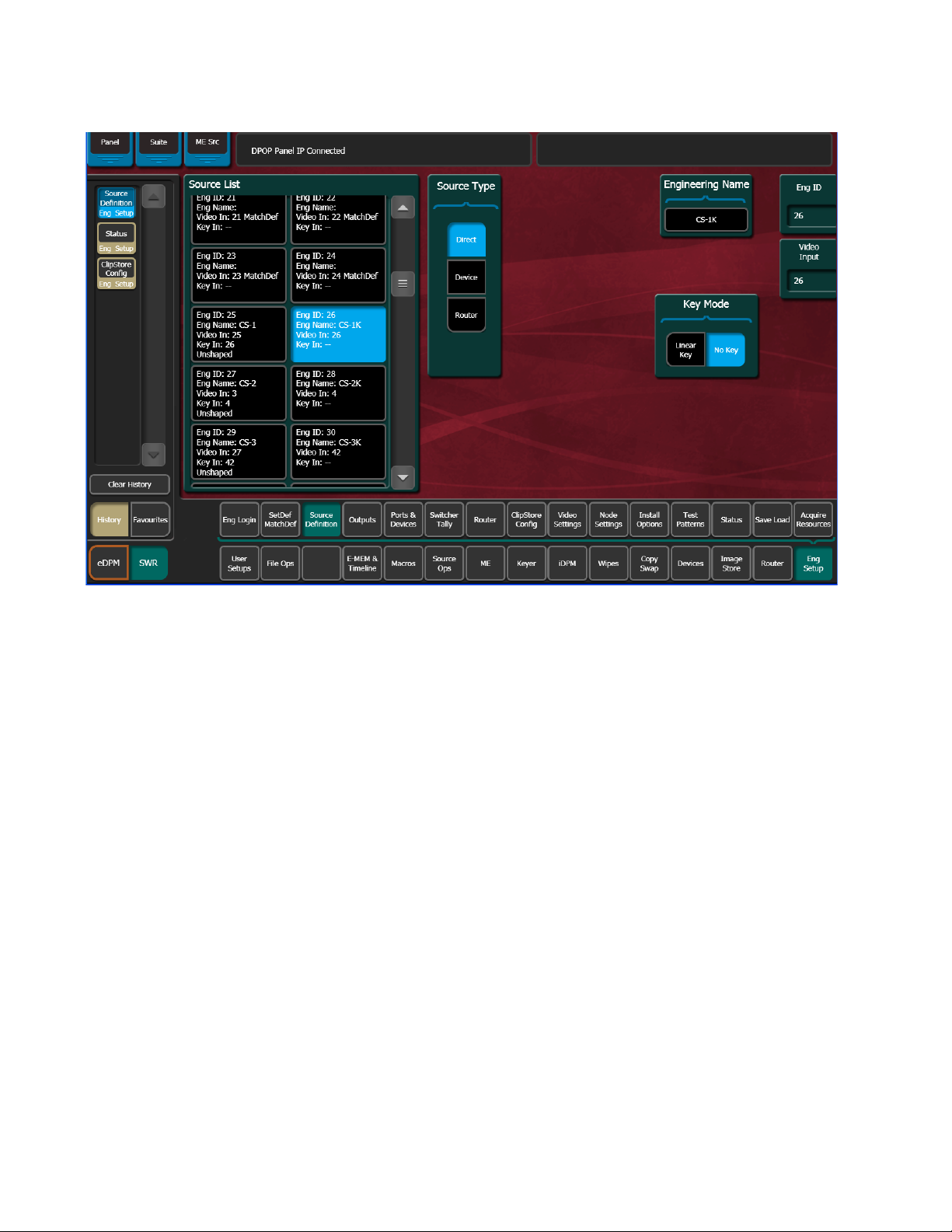
To configure a source as a ClipStore Key input (Key input to the ClipStore
Video input created earlier):
1. From the Source List, touch a source (Figure 9).
2. Tou ch t he No Key button in the Key Mode pane to select it (if not
selected).
3. Use the default video input (Video In:) or change it using the Video Input
data pad.
4. Tou ch t he Direct mode button in the Source Type pane to select it.
5. Give the ClipStore key input an Engineering Name if desired (CS-1K,
Figure 9), by touching the Engineering Name data pad and entering the
name in the pop-up keyboard.
KAYENNE — Release Notes 21
Page 22
Ver sio n 2. 0
Figure 9. ClipStore Key Input Source
You now have device control over this ClipStore resource, and it can be
mapped. Repeat the preceding steps for each ClipStore channel.
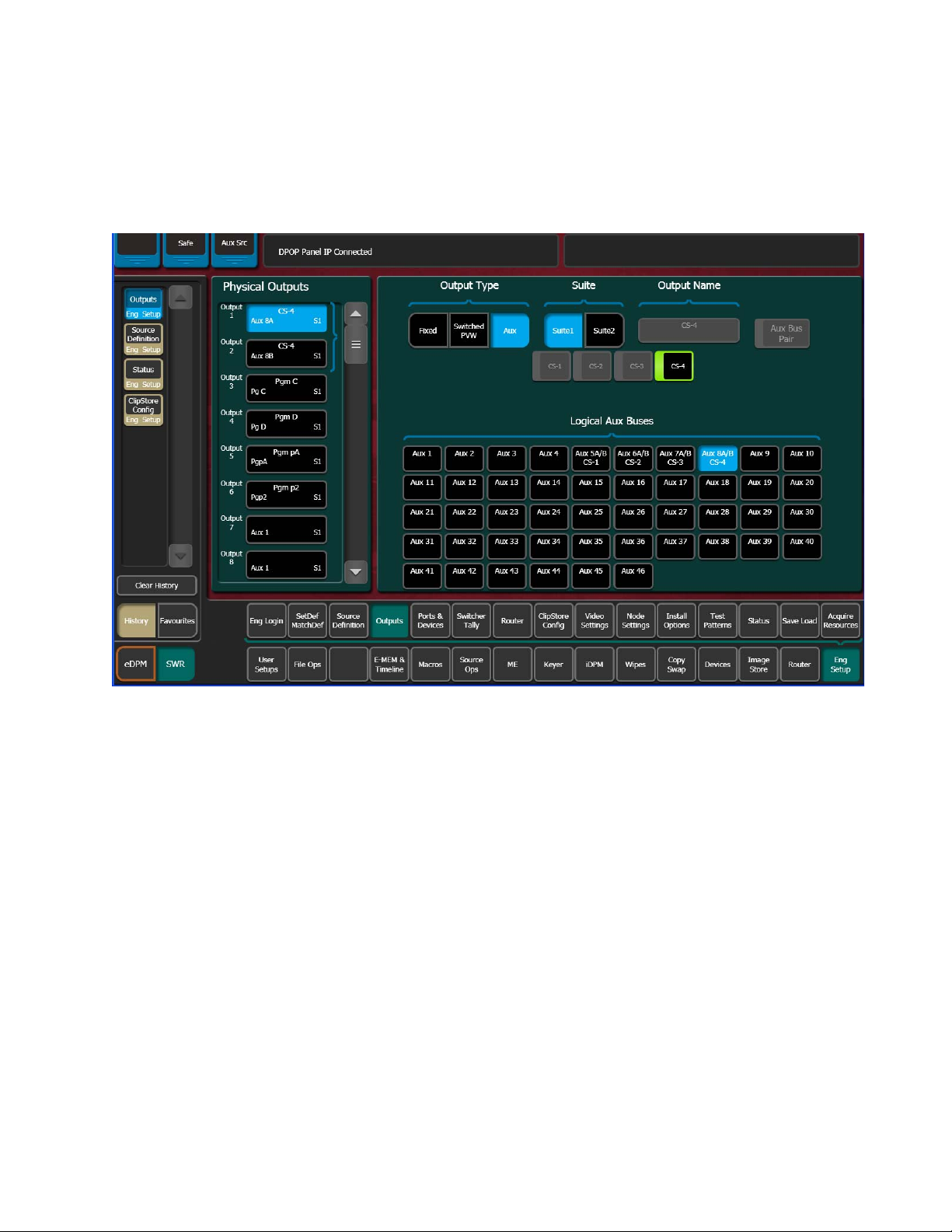
Configuring Outputs
Set the switcher outputs that are feeding into ClipStore. By selecting an Aux
bus then touching one of the CS-1 through CS-4 enable buttons, those Aux
bus outputs will be paired. In other words, if you select the output, then
22 KAYENNE — Release Notes
Page 23
ClipStore (Image Store Clips)
Aux 5, Aux 5a and Aux 5b will be paired as a ClipStore Video/Key pair
when the ClipStore button is enabled.
1. Go to the Outputs menu (Figure 10) by touching Eng Setup, Outputs.
Figure 10. ClipStore Output Configuration
2. Select the odd numbered output (first Aux bus output assigned for a
video/key pair must be odd/fill) that you wish to use as the input to
ClipStore (
desired logical Aux bus.
3. Touch one of the ClipStore buttons (Figure 10).
4. Repeat the preceding steps for each channel of ClipStore.
Note You only need to configure all channels as video/key if you wish to record on
The Engineering Names for each ClipStore channel will appear in the
Kayenne Local Aux Module and/or can be button mapped as desired.
When acquiring CS channels in another suite, before reassigning CS channels:
1. In the Outputs menu, deselect the CS channels to be acquired
(
Figure 10).
Figure 10). Then select Aux as the Output Type and the
all channels.
KAYENNE — Release Notes 23
Page 24
Ver sio n 2. 0
2. Tou ch t he Suite 1 or Suite 2 button (Figure 10) to change suite delegation.
3. Re-acquire the CS outputs by touching the CS buttons (CS-1, CS-2, etc.).
It is recommended at this point that you save a new Eng Setup file that
includes these changes.
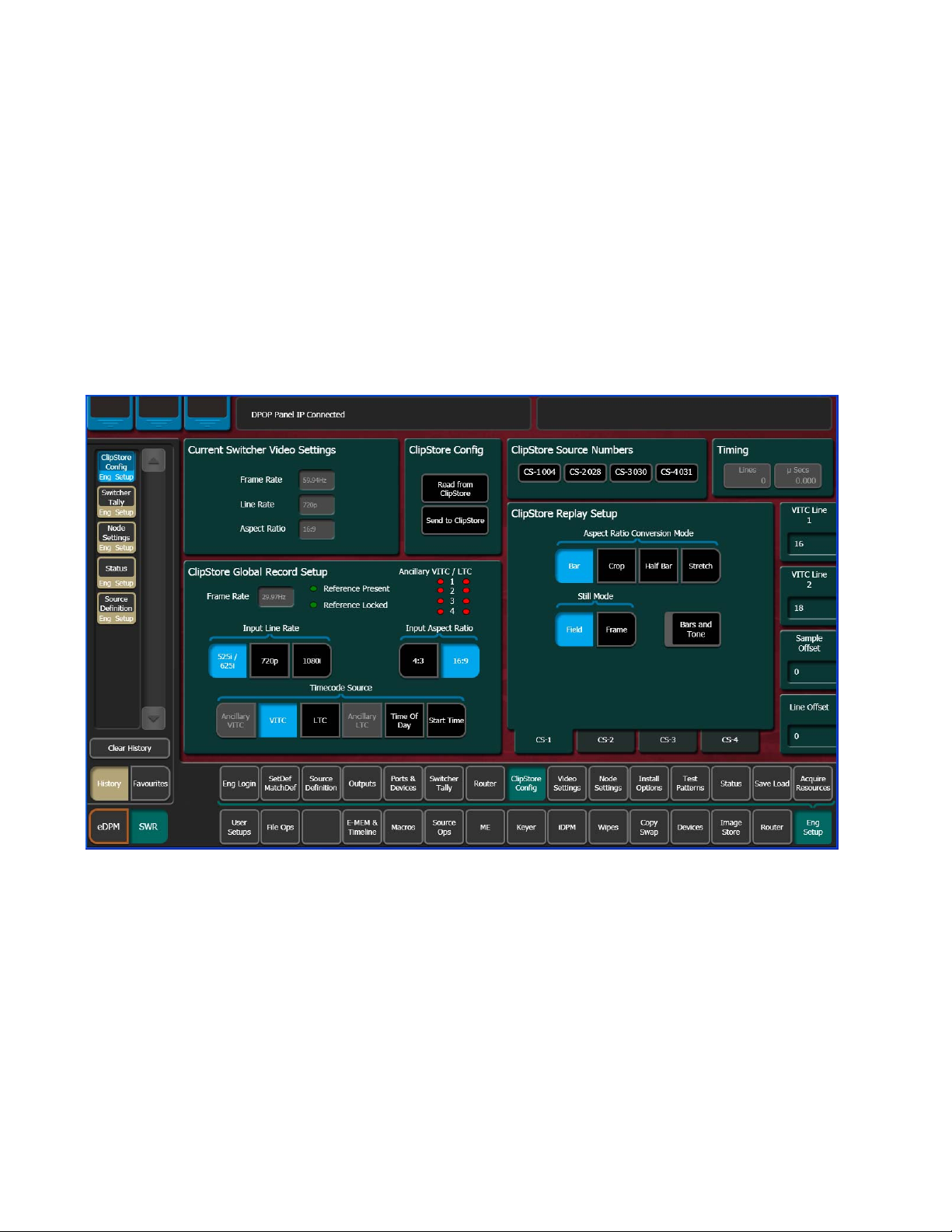
ClipStore Config Menu
The ClipStore Config menu is used to configure the ClipStore input/output
parameters and read those input/output parameters from, or send them to,
the ClipStore server (
Figure 11. ClipStore Configuration Menu
Figure 11).
Read from ClipStore button—Updates the Eng Setup, ClipStore Config menu
with the current parameter settings for the configured ClipStore server
channels (
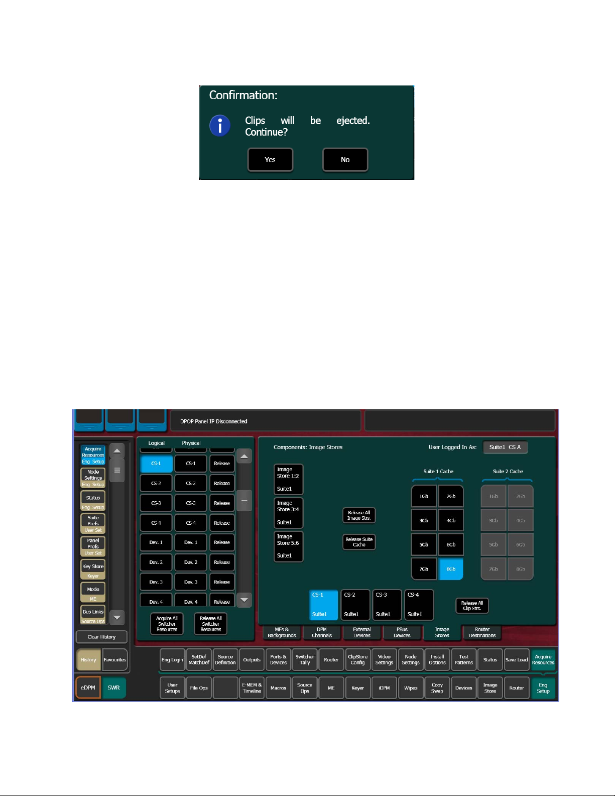
Send to ClipStore button—Sends all parameter and system settings required by
ClipStore to record, edit, and control clips to the server. Any changes to the
Record Setup or Replay Setup parameter settings will also be sent to the
ClipStore server (
pressed (Figure 12), stating that all clips will be ejected as part of this operation; keep this in mind if considering this operation during a broadcast.
Figure 11).
Figure 11). A dialog is displayed when this button is
24 KAYENNE — Release Notes
Page 25
ClipStore (Image Store Clips)
Figure 12. Send to ClipStore Confirmation Dialog
The ClipStore Source Numbers Pane (read-only), provides channel and
source information, for example CS-1025 means ClipStore Channel1 (CS-1),
Eng Source ID 25 (025).
Bars and Tone button—Turning this button on (highlighted green) then
touching the
figuration) and sends a tone to the selected ClipStore channel for testing.
Send to ClipStore button, loads color bars (and updates the con-
Assigning ClipStore Channel Resources to a Suite
ClipStore resources can be acquired in suites. ClipStore suite assignment
buttons have been added to the Eng Setup, Acquire Resources, Image
Stores menu (
see the Kayenne Installation and Service manual.
Figure 13). For information about acquiring suite resources,
Figure 13. ClipStore Acquire Resources
KAYENNE — Release Notes 25
Page 26

Ver sio n 2. 0
ClipStore as an External Device
Note ClipStores 1-4 as devices can only be enabled in the Eng Setup, Devices,
Node Settings menu in the Frame Suite Nodes & ID menu tab.
ClipStores 1-4 will appear as the first four external devices in the Device
Enables scrolling list (
Devices menus). External Device 1 will now be in the 5th position in the
Device Enables list (
menu do not function for ClipStore.
Note For a two-channel K2 Solo, only ClipStores 1 and 2 are reserved and External
Device 1 will be in the 3rd position.
ClipStore can be used in a gang like any other external device. For more
information about ganging devices, see the Kayenne User Manual.
Figure 14. ClipStore in Device Menu
Figure 14), in the Devices, Enables menu (and other
Figure 14). Enable/Disable buttons in the Devices
Kayenne Control Panel Operation
As with other external devices, device control is possible through the
MFM (Multi-Function Module), the optional DCM (Device Control
Module), and the System Bar. Engineering names (CS-1, CS-2, etc.) appear
26 KAYENNE — Release Notes
Page 27
in the control panel displays and all motion controls provided from the
server are available.
ClipStore motion controls can be learned as part of an E-MEM.
ClipStore Menu Operations
Clip Replay
The ClipStore output channels appear in the same columnar style as in the
Stills menu (
channel will be outlined in blue or red if on-air.
Note ClipStore channel represents a permanent Video/Key pair.
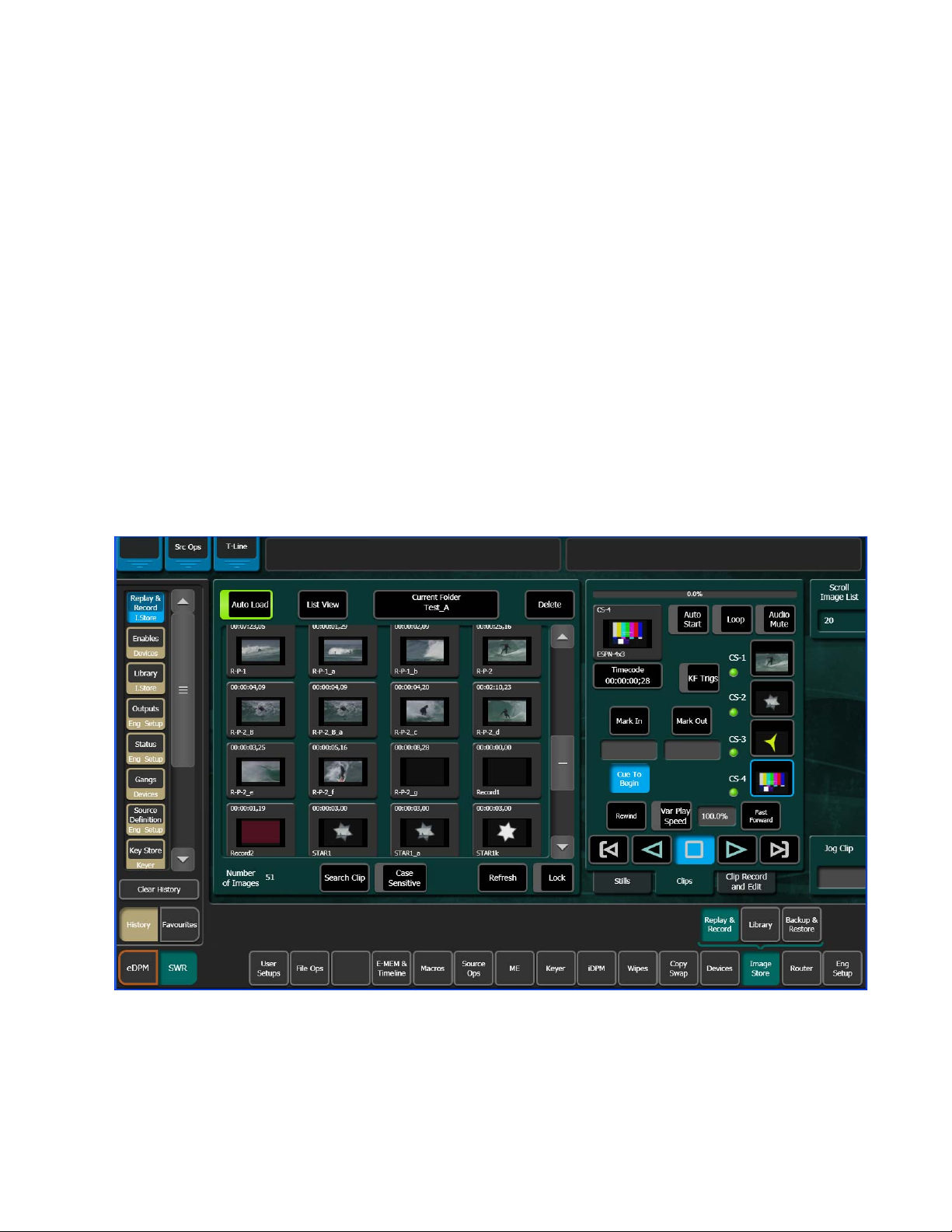
Clip replay is performed in the Image Store, Replay & Record, Clips (and
Clip Record and Edit) menu (
Figure 15). Also like the Stills menu, the selected output
ClipStore (Image Store Clips)
Figure 15).
Figure 15. Clips Menu
Folder Selection
Tou ch t he Current Folder data pad located just above the scrolling clip list
Figure 15) to change the current folder. The Folders/Clips menu is dis-
(
played (Figure 16).
KAYENNE — Release Notes 27
Page 28
Ver sio n 2. 0
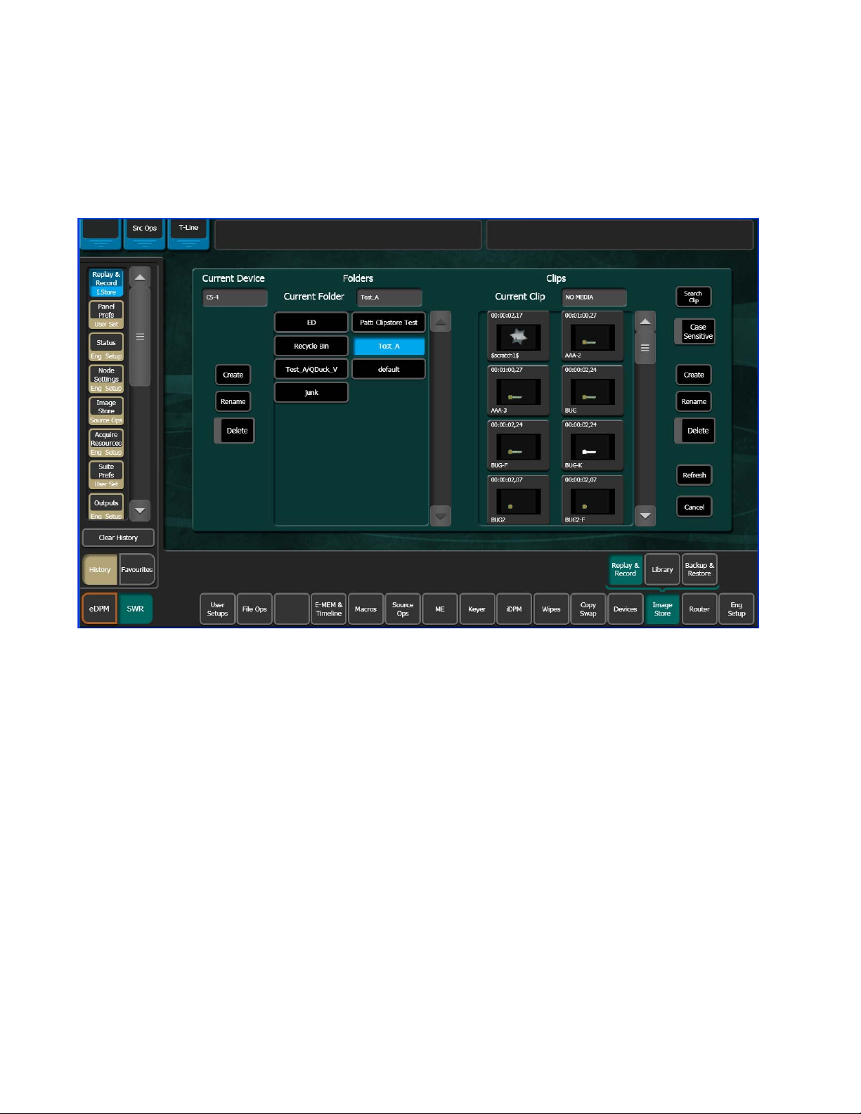
Touch the folder you wish to be the current folder and either select a clip on
the right or press the
close and return to the Clips menu (if the Cancel button is touched, the
folder will still be changed but it will not result in a clip load).
Figure 16. Folders/Clips Menu Selection
Cancel button (bottom right of menu, Figure 16) to
Menu Clip Selection
Clips can be selected in three ways in the menu:
• Touching a clip in the scrolling clip list (Figure 15),
• Touching the
Image ID for the clip (ascending numeric value in the current folder).
• Touching the Current Folders data pad and then touching a clip in the
Current Clip scrolling list (Figure 16).
With the Auto Load button selected (highlighted green), the clip will be
loaded into the selected ClipStore channel.
Scroll Image List data pad (Figure 15), and entering the
Clip Loading
As with Stills, to load a clip (Figure 15):
1. Turn on Auto Load by touching the Auto Load button.
Note Auto Load must be on to load a clip.
28 KAYENNE — Release Notes
Page 29
ClipStore (Image Store Clips)
Current
Thumbnail
Viewer
2. Touch a ClipStore channel.
3. Touch a clip in the scrolling clip list.
The clip loads to the selected channel.
The Current Thumbnail Viewer (Figure 17) displays the currently loaded
clip in the selected channel.
Figure 17. Current Thumbnail Viewer
Note When a ClipStore channel is selected and a clip is loaded, that clip will be
highlighted in
matically scroll to display the selected clip.
blue in the scrolling clip list (Figure 15) and the list will auto-
Clip Search
You can search for clips using the Search Clip button (Figure 15). Touching
the button displays the Search Clip keyboard. Type letters
and/or numbers (minimum 1 character) and touch Enter to execute the
search. The found clips will be listed in the scrolling clip list.
If Auto Load is on, the first clip in the resulting list will be loaded into the
selected channel. If Auto Load is off, or the search finds no clips, then no
clips will be loaded.
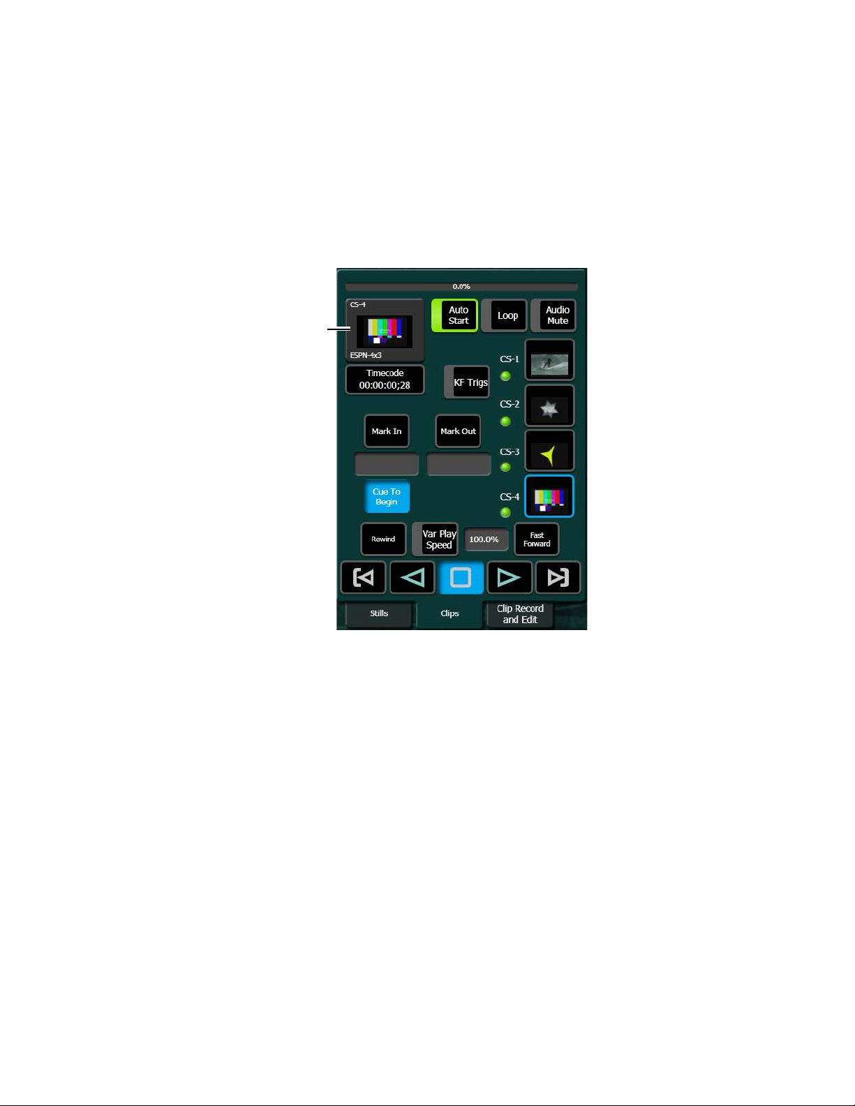
Playback
The Playback pane in the Image Store, Replay & Record, Clips menu provides playback and playback parameter controls for clips (Figure 18).
KAYENNE — Release Notes 29
Page 30

Ver sio n 2. 0
You can play a clip by loading it into a ClipStore channel and touching the
Play button, or by turning on the
on-air (
Figure 18). For example, if you take the CS-1 channel on-air, either
Auto Start button and taking the channel
as a background or keyer, the clip loaded into the CS-1 channel will play
automatically when the
Auto Start button is on.
You can loop a clip by touching the Loop button (highlights green) or mute
the audio of each channel individually with the
Figure 18).
(
Audio Mute button
Other controls include (Figure 18):
• Timecode data pad—Touch the Timecode data pad to enter a timecode.
Mark In/Mark Out buttons and data pads—Touch the Mark In/Mark Out
•
buttons to set the mark-in/mark-out to the current clip position, touch
the data pads to enter a Mark In or Mark Out point on a numeric
keypad.
Cue to In button data pad—Touch the Cue to In data pad and enter the
•
value.
Var Play Speed button and data pad—Var Play Speed button on, enables
•
variable speed play. Touch the data pad to enter the playback speed
value.
Device control buttons:
• Rewind
• Fast Forward
• Start of Clip
• Reverse Play
•Stop
•Play
• End of Clip
(The KF Trigs button is described in Replay with E-MEMs.)
Note All the functions listed above can be controlled by macros.
30 KAYENNE — Release Notes
Page 31

Figure 18. Playback Controls
Timecode
Data Pad
Clip Start
Reverse
Stop Play Clip End
Play
Mark In
Mark Out
Button/Data Pad
Audio Mute Icon
Variable Speed
Data Pad
Jog Clip Data Pad
(Soft Knob)
Button/Data
Pad
Cue to In
(Cues to
Mark In
set point)
ClipStore (Image Store Clips)
Replay with E-MEMs
ClipStore replay can be controlled with E-MEMs. Keyframe triggers that
are E-MEMable are:
• Load (Clip),
• Loop Enable/Disable,
• Cue (to in), and
• All Motion Controls including Variable Speed Play (
button).
Note The Master E-MEM has CS-1, CS-2, CS-3, and CS-4 assigned by default to
To create an E-MEM trigger, touch the KF Trigs button in the Image Store,
Clips menu (
buttons, and Loop Enable, Loop Disable and Cue buttons are displayed
(
Figure 19). When a Loop Enable, Loop Disable, Cue, or motion control button is
MISC 1-4.
Figure 19). The motion control buttons become jeweled toggle
Var Play Speed
KAYENNE — Release Notes 31
Page 32

Ver sio n 2. 0
touched, that operation will be learned by E-MEM. For more information
about E-MEMs, see the Kayenne User Manual.
Figure 19. Clip Replay with E-MEM Control
Recording Clips
Clips are recorded with embedded audio in the Image Store, Replay &
Record, Clip Record and Edit menus (
buttons (Figure 20) are positioned at the top right of the menu. To record,
the Record mode button must be selected (highlighted light blue, Figure 20).
Figure 20). The Record and Edit mode
32 KAYENNE — Release Notes
Page 33

Figure 20. Record Mode
ClipStore (Image Store Clips)
When the Record Enable button is touched, ClipStore ejects the clip from the
selected channel, places the ClipStore channels in E/E mode, and displays
a pop-up keyboard. Type in the name of the new clip. Once the name is
typed,
highlighted red and the menu has changed to display recording controls
and parameters in readiness for recording (
control button is replaced by a Record button.
Clips can be overwritten by entering an existing clip name into the pop-up
keyboard or by touching the
touching a clip (or folder then clip) in the Folders/Clips menu (
Once either operation is completed, you are returned to the Record mode
menu and the
Note Thumbnails do not display in the Current Thumbnail Viewer in Record Enable
Enter is pressed, and the keyboard closes, the Record Enable button is
Figure 21). The Play device
Cancel button in the pop-up keyboard and
Figure 16).
Record button is present and highlighted in red.
mode except when overwriting an existing clip.
KAYENNE — Release Notes 33
Page 34

Ver sio n 2. 0
Figure 21. Record Button Enabled
The Video and Key Record Elements buttons allow you to route the Aux Bus
selections:
• Video Only—Video + Full Raster White,
• Key Only—Key + Key, and
• Video/Key—Video + Key.
• Set a Record Time using the Record Time button.
Note If an Aux Bus is not configured for the ClipStore output, the Video and Key
buttons will always be on.
These elements are also very useful for editing when you want to build or
join clips (see
Time button and a pop-up keypad will appear to enter the desired value.
Tou ch
To record a clip:
1. Touch to select the ClipStore channel for recording.
2. Tou ch t he Record mode button.
3. Define the Record Elements you wish to apply to the clip to be
Enter when finished.
recorded.
Editing Clips on page 35). To set a record time, touch the Record
4. Tou ch t he Record Enable button.
34 KAYENNE — Release Notes
Page 35

5. Enter a new clip name or an existing clip name if you wish to overwrite
6. Tou ch Enter.
7. Tou ch t he Record device control button.
8. Tou ch t he Stop device control button when the desired length of the clip
Editing Clips
Clips can be edited in the Image Store, Clip Record and Edit menu. There
are three types of clip editing provided:
•Cut Edit,
• Build Edit, and
• Join Edit.
Cut Edit
ClipStore (Image Store Clips)
that clip.
is reached.
Cut Editing allows you to edit a clip in the following ways:
• Rename Clips (use the Rename button).
• Mark a thumbnail, see Cut Edit on page 35),
• Trim and remove from the head of the clip to the Mark In point (Tr i m
and Remove on page 37),
• Trim and remove from Mark Out point to the end of the clip (Tr im an d
Remove on page 37),
• Make sub-clips (including splitting one clip into two) from the current
clip (Make Sub-clips from the Current Clip on page 38), and
• Cut Edit while recording a clip (Cut Editing while Recording on page 39).
For Cut Edit, touch Image Store, Replay & Record, Clip Record and Edit and touch
the
Cut button in the Edit Type mode group (Figure 25).
KAYENNE — Release Notes 35
Page 36

Ver sio n 2. 0
Figure 22. Cut Edit Mode
Mark a thumbnail
The Cut Edit menu displays the currently loaded clip in the thumbnail
view. If you wish to change the clip, touch the
editing (
Figure 23).
Change Clip button before
36 KAYENNE — Release Notes
Page 37

Figure 23. Mark Thumbnail Point
ClipStore (Image Store Clips)
1. Tou ch t he Change Clip button to select a clip to edit (unless previously
loaded,
2. Either jog, shuttle, or play to the desired frame and touch the Mark
Thumbnail
3. Tou ch t he Mark Thumbnail data pad and enter the mark point in the pop-
up Mark Thumbnail Point keypad (
4. Tou ch t he Mark Thumbnail button (Figure 23).
The new thumbnail replaces the old in all views.
Figure 23).
button or,
Figure 23), and touch Enter.
Trim and Remove
Material can be removed from the head of a clip to a mark-in point and
from a mark-out point to the end of a clip. Both operations can be per
formed on a single clip.
-
KAYENNE — Release Notes 37
Page 38

Ver sio n 2. 0
Trim Clip operations include:
• Setting only the mark-in point, and touching the Trim C l ip button—the
clip will be trimmed from the beginning of the clip to the mark-in point.
• Setting only the mark-out point, and touching the
Trim Clip button—the
clip will be trimmed from the mark-out point to the end of the clip.
• Setting both a mark-in and mark-out point, and touching the
Trim Clip
button—the clip will be trimmed on both ends (beginning of clip to
mark-in and mark-out to end of clip).
To enter the mark-in/mark out points, either jog, shuttle, or play to the
desired frame and touch the
pad and enter the mark-in/out point in the pop-up keypad, and touch
Note Trim Clip to mark-in, trims up to the mark point in the clip so the marked
frame is the first frame of the new sub-clip.
CAUTION Trim Clip from the mark-out point, trims (removes) the marked frame and
trims to the end of the clip so the frame at the mark point will
the new sub-clip.
Mark In/Out button or touch the Mark In/Out data
Enter.
not be part of
Make Sub-clips from the Current Clip
A sub-clip can be created from the current clip with mark-in and mark-out
values (or without and the clip length will be the same as the original) or
split into two sub-clips.
1. To enter the mark-in/mark out points, either jog, shuttle, or play to the
desired frame and touch the
data pad and enter the mark-in/out point in the pop-up keypad, and
touch
Enter.
Mark In/Out button or touch the Mark In/Out
2. Tou ch t he Make Subclip(s) button.
3. Enter a clip name or accept the provided name (appends _a) and touch
Enter.
A new sub-clip with the trimmed length is created.
When making a split clip, the first clip is created from the current clip head
to the split mark point, the second from the split point to the clip end.
To split one clip into two sub-clips:
1. Either jog, shuttle, or play to the point in the clip where you want to
split the clip and touch the
2. Tou ch t he Mark Split data pad (below Mark Split button) and enter the
Mark Split button (Figure 24), or
value for the split point in the Mark Split Point pop-up keypad, and
touch
Enter (Figure 24).
38 KAYENNE — Release Notes
Page 39

Figure 24. Mark Split (One Clip Split into Two)
ClipStore (Image Store Clips)
3. Tou ch t he Make Subclip(s) button.
The Name First sub-clip pop-up keyboard is displayed.
4. Enter a name or accept the default name for the first sub-clip in the
Name First sub-clip pop-up keyboard (for the default, _a is appended
to the clip name).
5. Tou ch Enter.
6. Enter a name or accept the default name for the second sub-clip in the
Name Second sub-clip pop-up keyboard (for the default, _b is
appended to the clip name).
7. Tou ch Enter.
The two new sub-clips are created.
Cut Editing while Recording
A key advantage to using a ClipStore server is you can record and replay
simultaneously. This allows you to create sub-clips from the currently
recording clip.
KAYENNE — Release Notes 39
Page 40

Ver sio n 2. 0
The following rules apply to performing a Cut Edit operation during
recording:
• Making sub-clips is the only available operation.
• Only the Cut Edit type will be available.
• Changing the clip will not be possible from the menu during this operation.
Once recording has begun, you can touch the Edit mode button, set markin/mark-out points, and create a sub-clip (see
Current Clip on page 38).
A currently recording clip can also be loaded into another channel of ClipStore. From the other channel, sub-clips can be made from any part of the
recording without interrupting the record.
Make Sub-clips from the
40 KAYENNE — Release Notes
Page 41

ClipStore (Image Store Clips)
Build Editing
Build Editing (Figure 25) allows you to take elements from one long clip or
from multiple clips and make a sub-clip, including:
• Video and Audio (audio from a clip or .WAV file),
• Video (with embedded audio) and Key, or
• Video, Audio (audio from a clip or .WAV file), and Key.
CAUTION Audio files must be 48kHz/.WAV file format, other file types will not be
recognized by ClipStore.
Figure 25. Build Edit Mode
The clip created with the Make Clip operation will be a sub-clip that has its
head to tail length defined by the mark-in and mark-out points of the Video
track. (if there are no marks, the sub-clip created will be the same length as
the original). Both Audio and Key tracks of the new clip will only exist
inside the Video track’s marks.
Video is the controlling track in the scratch clip, i.e. the Audio, Key, and
motion control is slave to the Video track when selected.
Audio Offset, Key Offset, and Jog soft knobs are provided for editing (1/4 turn
equals 1 frame).
KAYENNE — Release Notes 41
Page 42

Ver sio n 2. 0
0.00 3.00
3.000.00
Audio/Key Track Timecode Position
Video Track Timecode Position
8623267_28
Mark In
Point
Mark Out
Point
Hold Sync
Point
Current Video
Timecode
Position
Hold Sync—Hold Sync sets the position of the Audio/Key track in relation to
the Video track’s current timecode position (
Figure 26). The Audio/Key
track’s timecode can be offset in relation to the video track timecode by
changing the Hold Sync Mark Point (using the
keypad or the
Audio/Key Offset soft knobs). In this way, the Audio/Key
Hold Sync data pad pop-up
tracks can be synchronized with the Video track. Different Hold Sync
Points can be set for the Audio and Key tracks in relation to the Video.
Note If a key track from another clip is used, and starts past the mark-in point of
the video track, full raster white will be used for the key until the key timecode
begins when the composite clip is played. If an audio element from another
clip is used, and starts past the mark-in point of the video track, there will be
no audio until the start of the audio timecode when the composite clip is
played.
Once the Hold Sync button is touched for either the Audio or Key, the Hold
Sync point will be set and their positions in relation to the current video
track timecode position become part of the scratch clip, and subsequently
the new sub-clip when the
Note You can still change any of the current timecode values, including the video
timecode by changing the mark-in/mark-out points and the Audio/Key timecode using the Hold Sync data pad or Audio/Key Offset soft knobs, before
the Make Clip button is touched. Each change updates the scratch clip.
Make Clip button is touched.
Figure 26. Hold Sync Point
The following provides examples and procedures of how to combine elements of Video, Audio, and Key. These composited elements become part
of the new sub-clip.
These procedures can also be used to make a composite clip of elements on
one long clip, for example if both Video and Key track are recorded on one
42 KAYENNE — Release Notes
Page 43

ClipStore (Image Store Clips)
clip, the clip can be loaded as the Video track and then as the Key track, synchronized, and then a sub-clip made of the composite elements.
As with other ClipStore editing operations, if you enter the name of an
existing clip, that clip will be overwritten when creating a sub-clip using
the Make Clip operation.
Editing a Video Clip with Build Edit—The following example is of how to mark-
in, mark-out, mark a thumbnail, and make a sub-clip. The
Video
and Use Key From Video buttons are enabled (highlighted green) which
means only the video track will be edited and a new clip made with those
changes:
Tou ch Image Store, Replay & Record, Clip Record and Edit and touch the Build
button in the Edit Type mode button group (
Figure 27. Build Edit Mode—Video Only Edit
Figure 27).
Use Audio From
1. Unless the desired clip is loaded, touch the Video Thumbnail Viewer
(
Figure 27).
2. Tou ch t he Change Clip button for the Video and touch the desired clip
Figure 27).
(
KAYENNE — Release Notes 43
Page 44

Ver sio n 2. 0
3. Determine where you want a mark-in point for the Video track by
either playing/jogging to the mark while viewing the clip on a monitor
and touching the
Mark In button (Figure 27) or if you know the timecode,
touch the Mark In data pad and enter the timecode into the pop-up
keypad, and touch
4. Determine the mark-out point for the Video track and enter it as
Enter.
described for Mark In.
Mark a Thumbnail
1. Jog, shuttle, or play to where you want to mark thumbnail and touch
the
Mark Thumbnail data pad, or
2. Tou ch t he Mark Thumbnail data pad and enter the mark-thumbnail point
in the pop-up keypad, and touch
Enter.
With the Video Thumbnail Viewer selected, you can test the composite elements using the motion control buttons.
Make the Sub-clip
1. Tou ch t he Make Clip button.
2. Enter the name of the new clip and touch Enter.
The new clip is created and appears in the clip lists in the ClipStore menus.
Note If Multiple sub-clips are desired from a built clip, use Build Edit to make the
whole clip and then use the Cut Edit to make multiple sub-clips.
Adding a New Audio Element with Build Edit—If you require audio before or after
video, a video track (for example of black) is needed so a mark can be made
(this can be added with Join Edit, see
Join Edit on page 47).
In this case, you want to use the Video and Key of the loaded Video track
but add/replace the Audio track and make a sub-clip. The
Use Key From Video
button is enabled (highlighted green):
1. Unless the desired clip is loaded, touch the Video Thumbnail Viewer
Figure 28).
(
44 KAYENNE — Release Notes
Page 45

Figure 28. Build Edit Mode—Audio Track Edit
ClipStore (Image Store Clips)
2. Tou ch t he Change Clip button for the Video and touch the desired clip
Figure 28).
(
3. Determine where you want a mark-in point for the Video track by
either playing/jogging to the mark while viewing the clip on a monitor
and touching the
touch the Mark In data pad and enter the timecode into the pop-up
keypad, and touch
4. Determine the mark-out point for the Video track and enter it as
described for Mark In.
5. Turn off the Use Audio From Video button (Audio section) by touching it
Figure 28).
(
6. Tou ch t he Audio Thumbnail Viewer.
7. Tou ch t he Change Clip button and touch the desired clip/.WAV file with
the desired Audio track.
8. Synchronize the Audio track in relation to the current video track
timecode position, if needed, using the
Offset
soft knob (see page 42 for more about Hold Sync).
Mark In button (Figure 28) or if you know the timecode,
Enter.
Hold Sync data pad or the Audio
KAYENNE — Release Notes 45
Page 46

Ver sio n 2. 0
With the Video Thumbnail Viewer selected, you can test the composite elements
using the motion control buttons.
Make the Sub-clip
1. Tou ch t he Make Clip button.
2. Enter the name of the new clip and touch Enter.
Add/Replace a Key Element with Build Edit—In this case, you want to use the
video and audio of the loaded video element but add/replace the key track
and make a sub-clip. The
green):
1. Unless the desired clip is loaded, touch the Video thumbnail viewer
(
Figure 29).
Figure 29. Build Edit Mode—Key Track Edit
Use Audio From Video button is enabled (highlighted
2. Tou ch t he Change Clip button for the Video and touch the desired clip
(
Figure 29).
3. Determine where you want a mark-in point for the Video track by
either playing/jogging to the mark while viewing the clip on a monitor
and touching the
touch the Mark In data pad and enter the timecode into the pop-up
keypad, and touch
Mark In button (Figure 29) or if you know the timecode,
Enter.
46 KAYENNE — Release Notes
Page 47

ClipStore (Image Store Clips)
4. Determine the mark-out point for the Video track and enter it as
described for Mark In.
5. Synchronize the Key track in relation to the current video track
timecode position, if needed, using the
Offset
soft knob (see page 42 for more about Hold Sync).
With the Video Thumbnail Viewer selected, you can test the composite elements using the motion control buttons.
Make the sub-clip
1. Tou ch t he Make Clip button.
2. Enter the name of the new clip and touch Enter.
Hold Sync data pad or the Key
Join Edit
Join Edit allows you to append one clip to another, and mark a thumbnail
if desired.
To go to the Join Edit mode menu, touch Image Store, Replay & Record, Clip
Record & Edit
(
Figure 30).
and touch the Join button in the Edit Type mode group
KAYENNE — Release Notes 47
Page 48

Ver sio n 2. 0
Figure 30. Join Edit Mode
1. Touch the Change Clip button for the first clip (top thumbnail) and touch
the desired clip.
2. Tou ch t he Change Clip button for the second clip (bottom thumbnail) to
be appended to the tail end of the first, and touch the desired clip.
3. Mark a thumbnail if desired (optional).
a. Determine where you want to mark thumbnail and touch the Mark
b. Enter the mark-thumbnail point in the pop-up keypad and touch
4. Tou ch t he Make Subclip(s) button.
The new clip is created and appears in the clip lists in the ClipStore menus.
File Operations
ClipStore file transfers are performed in the ClipStore Library menu. Touch
Image Store, Library. Files can be imported or exported using the Copy/Paste
(or
Cut/Paste in the case of ClipStore to ClipStore folder transfers) buttons
in the To and From ClipStore and Disk/Folder menu tabs (
Thumbnail
Enter.
data pad, or
Figure 31).
Note File renaming is not supported in the ClipStore Library menus.
48 KAYENNE — Release Notes
Page 49

ClipStore (Image Store Clips)
File transfers can be performed from/to the following locations from the
Kayenne Menu Panel:
• ClipStore Server,
• Image folder on the Kayenne Menu Panel,
• USB Storage Devices (seen as Removable Disks) and
• External USB Disk Drives (seen as Hard Disk Drives).
USB storage devices can be inserted into the USB ports on both the ClipStore server and on the Kayenne Menu Panel. Memory Sticks will be seen
as Removable Disks and will be displayed in the From Disk/Folders and
To Disk/Folders menu tabs. External USB Disk Drives will also be seen in
the From and To Disk/Folders menu tabs however first a shared folder is
needed on the device (see
Drives on page 50).
Figure 31. ClipStore Library Menu—File Transfer
Creating a Shared Folder for External USB Disk
Both files and folders containing files can be copied from disk to the ClipStore server. However, folders can only be copied to the top directory of the
ClipStore server, “nested” folders are not permitted.
Files can be exported in multiple formats, by touching the mode buttons in
the
Export Format modes pane (Figure 31). This operation is only supported
when the files selected for export are in the From ClipStore pane. Files in
Video/Key format can only be exported in GXF format.
KAYENNE — Release Notes 49
Page 50

Ver sio n 2. 0
Note If a folder is selected for export, all files within the folder will be exported with
the same format.
Creating a Shared Folder for External USB Disk Drives
To exchange files with an external USB disk drive, you will need to create a
shared folder in the device, in Windows:
1. Insert the USB connector for the external USB drive in the Menu Panel.
2. Minimize the Kayenne menu.
3. Open My Computer from the Desktop.
4. Open the disk drive from the Hard Disk Drives list.
5. Create a new folder using the File menu, name the folder (for example
“Kayenne Clips”).
6. Right-Click on the folder, and choose Sharing and Security from the pull-
down menu.
7. In the Sharing tab, select the Share this folder radio button.
8. Press the Permissions button.
9. Allow full control for Everyone.
10. Click Apply.
The folder is now shared. The new folder will be available in the Image
Store, Library, From/To Disk Folders menu tabs.
Changes to the Stills Menu
The Image Store Stills menu has been changed with Kayenne 2.0. Changes
include (
• Capture Still menu tab removed, replaced with menu when Capture Still
•
•
Figure 32):
button is pressed.
Reserve Space button removed.
Change Description button added (displays pop-up keyboard to change
image description).
50 KAYENNE — Release Notes
Page 51

Figure 32. Image Store Still Menu Changes
ClipStore (Image Store Clips)
KAYENNE — Release Notes 51
Page 52

Ver sio n 2. 0
Key Chaining
New with Kayenne 2.0, Key Chaining allows you to chain keys to coordinate their keyer states (on and off) on a single ME or from one ME to
another. There are 15 Key Chains available in a Kayenne System. All keys
in a chain transition on and off together. Key Chaining is performed in the
User Setup, Suite Prefs, Key Chaining menu (
Some uses for Key Chaining are:
• Keyers within an ME for language or Ident separations of clean feeds,
• Aspect ratio-specific graphics across more than one ME, or
• Advertising graphics on bus-linked MEs which already substitute
background pictures.
In the Key Chaining menu, you can configure which keyers are chained
together in each chain. The following rules apply:
• Each keyer may not be in more than one Key Chain.
• All keyers in a Key Chain will be equal in command priority.
Figure 33).
Key Chaining is part of the Kayenne configuration and saved as part of
File
been added to this menu.
Keyers are controlled from the Transition Module on the Kayenne Control
Panel. They can be cut on/off or transitioned on/off using the dedicated
Key Cut and Auto buttons. Key chaining allows for a single button push to
transition all the keys in the chain. A single keyer selection in the NextTransition area of the Module will similarly cause the other keys in the
chain to be selected. Then a single push of the Auto button or movement of
the Lever Arm will cause all of the keys in the chain to transition on one or
more MEs simultaneously.
Creating Chains
To create a Key Chain or chains in a single ME, simply touch a Chain
parameter data pad (Chain 1, Chain 2, etc.,
blue), and touch the keys you wish to add to the chain. Touch another
Chain parameter data pad and repeat the process (for the same ME in this
case).
Ops, Suite Prefs. A layer of load granularity (Key Chaining button) has
Figure 33) to select it (turns
52 KAYENNE — Release Notes
Page 53

Key Chaining
The Chain parameter data pads display each ME and either dashes (if
empty) or Keys 1-6 if keys are enabled for that ME in the chain (
Figure 33. Key Chaining Menu
Figure 33).
Once a keyer is enabled as part of a chain, the button is grayed out as each
key can only be part of one chain.
The Release ME Keys and Release All Keys buttons are provided to help manage
Key Chain configuration.
Using Key Cut/Auto Buttons
Pressing any of the K1 Cut - K6 Cut or K1 Auto - K6 Auto buttons in the Transition
Module of an ME, with those keyers as part of a chain, will result in the fol
lowing:
• Chained keyers on the same or different MEs all transition simultane-
ously,
• The transition rate of the button that is pressed (controlling keyer) is
applied to all the other (controlled) keyers in the chain.
-
KAYENNE — Release Notes 53
Page 54

Ver sio n 2. 0
Key Chaining on a Single ME
As shown in Figure 34 (in blue), in the Chain parameter data pads, the following three key chains have been created for ME 1:
• Chain 1—Keys 1 and 2,
• Chain 2—Keys 3 and 4, and
• Chain 3—Keys 5 and 6.
Figure 34. Key Chaining Menu—Single ME Key Chaining
Selecting keyers in the Next-Transition section of the Control Panel will
make those keyers initiators for the transition. Key Chaining causes the
chained (controlled) keyers to be selected as well. These chained keyers will
flash to indicate they are in the chain. The keys which do not flash are the
initiators. When the Lever Arm is moved, or the
keys transition together.
If a selection is made for a keyer in the primary partition, and the chained
controlled key is in the secondary partition, the controlled keyers will tran
sition simultaneously with the keys in the primary partition, irrespective of
the delegation of the
for selections made in the secondary partition with controlled keys in the
primary; they always delegate whether or not the
Module) is delegated. This behavior corresponds to the tally of the nexttransition buttons. The blinking tally indicates that the keys will transition.
SEC button (Source Select Module). The same is true
Auto button is pressed, the
PRI button (Source Select
-
54 KAYENNE — Release Notes
Page 55

Key Chaining Across MEs
As shown in Figure 35 (in blue), in the Chain 1 parameter data pad, the following multiple ME key chain has been created:
• PGM/PST, Key 1,
• ME3 Key 1, and
•ME1 Key1
Figure 35. Key Chaining Menu—Multiple ME Key Chaining
Key Chaining
Selecting a keyer in the Next-Transition section of the Control Panel will
make that keyer the initiator. On the MEs with keyers in the chain, their
next-transition selections will be erased and the keyers in the chain
selected. These keyers will flash to indicate that they are in the chain. The
key which is not flashing is the initiator.
You can also use the Cut/Auto keys as described in Using Key Cut/Auto
Buttons on page 53. If a Cut button is pressed on the initiating ME, then all
the MEs with chained keyers, cut. If an Auto button is pressed, then similarly, all MEs with chained keyers shall perform the same transition at the
same rate.
Other non-chained keys or other transition elements can be added to the
next-transition at this time.
KAYENNE — Release Notes 55
Page 56

Ver sio n 2. 0
Key chains can be established with keys both in the same and different
MEs.
56 KAYENNE — Release Notes
Page 57

Multiple Bus Linking
New with Kayenne 2.0, you can now create multiple bus links (Figure 36);
referred to as Parallel and Cascading Links. Also, you can define and associate one of the 15 new definable Source Substitution Tables to a bus (each
controlling and linked bus can be associated with any Source Table), and
save Bus Links as part of an E-MEM. Bus Links are now Keyframeable.
Note Bus Links created and E-MEMs learned using earlier versions of Kayenne
Bus Link is now an E-MEM sub-level in the User Setups, Suite Prefs, E-MEM
Prefs menu and therefore all the features and controls of a Kayenne
switcher sub-level now apply.
One-to-one, one-to-many (Parallel), and one-to-one-to one (Cascading)
links can exist simultaneously in the Bus Links, Links Setup menu
(
Figure 36).
Figure 36. Multiple Bus Links
Multiple Bus Linking
software must be rebuilt after upgrading to Kayenne 2.0.
Selected Controller and Linked bus buttons turn blue when selected in the
Current Link pane. In the example in
PGM U2 is the selected button.
Figure 36, the Linked bus button
KAYENNE — Release Notes 57
Page 58

Ver sio n 2. 0
Configuring Source Substitution Tables
For information about the Bus Hold Inhibits Links and All Links buttons, see the
Kayenne User Manual.
Source Tables have been added as part of the Bus Link enhancements with
Kayenne 2.0. There are now 15 additional configurable Source Tables. Each
can be assigned to one, many, or all Bus Links once configured in the Source
Tab les men u (
In earlier versions of Kayenne, source substitutions could be made on each
linked bus but each was treated separately so resources were consumed for
every source selection action. Now, instead, a Source Table (or lookup table)
can be configured and applied to every Controller/Link bus which frees up
resources and allows a faster more efficient way of applying the same
source substitutions to multiple links. Also, you are now able to create
named relationships between the Source Table and the links to which they
are assigned.
Figure 37).
Standard Table All Sources 1-to-1 Source Table is the default until one of the 15
configurable Source Tables is assigned.
In the example in Figure 37, Source Table 15 (Engineering Name) has been
configured with source substitutions using the Source Tables menu and
renamed “Home Team”. This Source Table can now be easily identified and
58 KAYENNE — Release Notes
Page 59

Multiple Bus Linking
Source List for
Linked Source
Column
assigned to one or many Controlling or Linked busses in the Bus Links,
Links Setup menu (
Figure 37. Source Tables
Figure 36).
To give a Source Table a descriptive name, touch the Rename button and
enter the name into the pop-up keyboard, and touch
Enter.
Table Setup, Linked Source buttons:
Set All One to One—Sets all sources one-to-one.
Set to None—Sets selected source’s Linked Source to none (blank).
Set All to None—Sets all Linked Sources to none (blank).
Set All to Current—Sets all Linked Sources to the currently selected Source
(including none if defined).
Store button—Allows the current source table to be copied to another
source table.
Note The Store button stores (or copies) the currently selected source table
assignments to another source table.
To configure a Source Table with source substitutions, use the Table Setup
pane (
Figure 37). The default is one-to-one, i.e. Source 1, Linked Source 1,
Source 2, Linked Source 2, etc. You can substitute the current Link Source
KAYENNE — Release Notes 59
Page 60

Ver sio n 2. 0
Source Table File Operations
with any source from the scrolling Source List (Figure 37, far right of
menu):
1. Rename the Source Table if desired.
2. Touch to select a source in the Source column of the Source/Link Source
scrolling list.
3. Touch the source in the scrolling Source List (Figure 37), far right of
menu) you wish to substitute for the current Link Source; the Linked
Source changes to reflect your selection.
4. Repeat the first two steps for all source substitutions.
The Source Table will be updated in the Bus Links, Links Setup menu
with the new name (
Source Tables now are part of Kayenne file operations; File Ops, Source
Tables menu. You can perform all the same file operations: copy, paste,
save, load, etc., as with other File Ops menus. For more about File Oper
ations, see the Kayenne User Manual.
Figure 36) and can be assigned to links.
-
60 KAYENNE — Release Notes
Page 61

Linking Multiple Busses
Multiple bus linking is divided into two categories: Parallel Links and
Cascading Links.
Source Tables can be setup for both Parallel and Cascading Links,
however the default will be “Standard Table All Sources 1-to-1”, or 00
as seen in the Current Link, Linked Bus data pads.
Touching the Controlling Bus or Linked Bus data pads in the Bus Links,
Links Setup menu displays the Bus Picker pop-up menu for each, from
which to choose linked busses (
Figure 38. Bus Picker Pop-up
Multiple Bus Linking
Figure 38).
KAYENNE — Release Notes 61
Page 62

Ver sio n 2. 0
Parallel Links
Parallel Links allow the controlling bus to control more than one linked
bus. In the example in
Aux 2, and ME1 Key1, are all linked in parallel to PGM A.
Figure 39. Parallel Links
Figure 39, PGM A is the controlling bus and Aux 1,
To create parallel links:
1. Tou ch t he Controlling Bus data pad in the Table Setup pane; the
Controlling Bus selection menu is displayed.
2. Tou ch t he ME busses, Aux Busses, or eDPM Inputs tab and touch the desired
bus. The menu closes and returns to the Bus Links menu. The selected
bus is displayed in the
Figure 39, the selected bus is PGM A).
3. Tou ch t he Linked Bus data pad in the Table Setup pane; the Linked Bus
selection menu is displayed.
4. Tou ch t he ME busses, Aux Busses, or eDPM Inputs tab and touch the desired
bus. The menu closes and returns to the Bus Links menu. The selected
bus is displayed in the
Controlling Bus data pad (in the example in
Linked Bus data pad.
62 KAYENNE — Release Notes
Page 63

5. Tou ch t he Linked Bus data pad again and touch the next bus you wish to
link to the controlling bus. The Bus Links menu now displays in the
Current Link pane, the controlling bus and two linked busses that are
linked to the controlling bus (in the example in
PGM A and Linked Aux 1 and LInked Aux 2).
6. If desired, assign a different Source Table to the Linked Bus:
a. Touch a Linked Bus data pad in the Current Link pane.
b. Touch a Source Table in the Table Setup pane.
Note Source Tables can only be assigned to Linked busses.
Cascading Bus Links
In Cascading Links, a controlling bus (A) has a linked bus (B) which in turn
acts as the controlling bus for another linked bus (C), and so on. Changing
a source on the controlling bus (A) will cause a change on both linked
busses (B and C).
Multiple Bus Linking
Figure 39, Controller
In the example in Figure 40, Controller PGM A controls Linked Aux 1,
Linked Aux 1 is the controller for Linked Aux 2, and Linked Aux 2 is the
controller for Linked Aux 3.
Button Color Definitions—The following applies for Cascading Links in the
Current Link pane, as seen in the example in
• Black—Controller but not controlled: PGM A Bus is a controller but is
not controlled so it is black in color.
• Green—Controlled and controls: Aux 1 Bus and Aux 2 Bus although
controllers, are also controlled so they are green in color.
• Blue—Aux 3 Bus is controlled but is not a controller therefore it is blue.
Figure 40:
KAYENNE — Release Notes 63
Page 64

Ver sio n 2. 0
Figure 40. Cascading Bus Links
To create cascading links:
1. Tou ch t he Controlling Bus data pad in the Table Setup pane; the
Controlling Bus selection menu is displayed.
2. Tou ch t he ME busses, Aux Busses, or eDPM Inputs tab and touch the desired
bus. The menu closes and returns to the Bus Links menu. The selected
bus is displayed in the
Figure 40, the selected bus is PGM A).
3. Tou ch t he Linked Bus data pad in the Table Setup pane; the Linked Bus
selection menu is displayed.
4. Tou ch t he ME busses, Aux Busses, or eDPM Inputs tab and touch the desired
bus. The menu closes and returns to the Bus Links menu. The selected
bus is displayed in the
5. Tou ch t he Controlling Bus data pad again, in the Table Setup pane; the
Controlling Bus selection menu is displayed. Touch the same bus as is
currently displayed in the
The linked bus is now also a controlling bus.
6. Tou ch t he Linked Bus data pad again in the Table Setup pane and select
another linked bus.
Controlling Bus data pad (in the example in
Linked Bus data pad.
Linked Bus data pad (your previous selection).
Repeat this process for each controlling and linked bus you wish to add
to the cascading links.
64 KAYENNE — Release Notes
Page 65

Corner Pinning
8623267_31
Corner Pinning
Corner Pinning allows you to move the corners of a source image relative
to the background. Corner Pinning is keyframeable, with all standard path
control functions. The new corner locations do not need to form a rectangle.
Corner Pinning is accomplished by distorting the source to fit into its newly
defined corners. The modified image remains in its original source plane,
and is not “bent” along the Z axis. Corner Pinning does not change the loca
tion of the axis of rotation or spin of the source image.
Figure 41. Corner Pinned Object
-
Corner Adjust Limits—Corner Pinning works for convex quadrilaterals but not
for concave quadrilaterals. A convex quadrilateral is defined as a foursided shape with all angles less than 180 degrees (
point outwards and all diagonals lie entirely inside the quadrilateral.
Results from adjusting a corner beyond the limits are undefined.
Figure 42. Convex Quadrilateral—Corner Adjust Limits
180 Degrees
Figure 42), all vertices
8623267_33
KAYENNE — Release Notes 65
Page 66

Ver sio n 2. 0
Corner Pinning and Cropping
To allow fine adjustment of an image when using Corner Pinning, the View
Through (View Thru Enable) feature allows you to temporarily (for editing
purposes only) reduce the opacity of an iDPM channel to let you “look
through” the image to align the corners precisely with the background.
Corner Pinning is designed to work in conjuction with cropping. After
pinning the corners of an image you can crop it to select the exact portion
of the source video to display in the corner pinned area.
For example, your source video could contain two people, but you may
want to fly the image of only one person (
build an effect, turn on Corner Pinning, use crop mode, and leave the
corners at the defaults. If you now move the crops maintaining the original
aspect ratio (4x3 or 16x9) you can position these crops so that only the
desired person is shown. If the person or the camera moves, you can adjust
the user crops to keep the person centered between the edges of the crops.
This will result in the person being centered in the video and the effect can
be flown around the screen.
Figure 43). In this case, you could
Figure 43. Corner Pinned Cropped Object
8623267_32
66 KAYENNE — Release Notes
Page 67

Corner Pinning Menu
The Corner Pinning menu (Figure 44) is available in both the SWR
(Switcher) (iDPM, Corner Pinning) and the eDPM (option) mode (eDPM,
Corner Pinning). The menus function identically.
Figure 44. iDPM, Corner Pinning Menu
Corner Pinning
KAYENNE — Release Notes 67
Page 68

Ver sio n 2. 0
Tou ch t he eDPM mode button (lower left), eDPM, Corner Pinning (Figure 45).
Figure 45. eDPM, Corner Pinning Menu
An example of how Corner Pinning would be valuable is that during a
sporting event, a camera points at a shot clock. The DPM uses Corner
Pinning to build a box to contain the clock and crop adjustments place the
clock exactly in the box but the camera is accidentally moved and the
content of the box no longer shows the entire shot clock. Using Pan and
Scan, you can move the camera content to be shown correctly without
moving the edges of the box.
Note Crop enables/disables and crop edge parameter changes are global. For
example, if crops are enabled in the iDPM, Transform menu, and the top crop
edge parameter was changed, the effect would be mirrored in the Corner
Pinning menu and vice versa in the iDPM, Corner Pinning menu.
1. Select a background source.
2. Select a source for a keyer, and cut on the key over the background.
3. Go to the iDPM, Transform menu and touch the Crop On button to turn
it on (highlights green).
4. Touch the Crop Edge data pad (turns light blue), the Crop Edge soft knobs
will be displayed.
68 KAYENNE — Release Notes
Page 69

Corner Pinning
5. Adjust the crop edges to include the portion of the video you want in
the key.
6. Go to the iDPM, Corner Pinning menu (Figure 46).
Figure 46. Corner Pinning On
7. Tou ch t he Corner Pinning On button to turn it on (highlights green).
The image will fill the screen—each corner of the key is now pinned to
the corners of the monitor.
8. Tou ch t he All button in the Corner Adjust area of the Corner Adjust/
Crop Adjust pane. Adjusting the iDPM with the Corner Pinning
button enabled, acts similar to a zoom. Use the
adjust the size of the key; in this case to the approximate size of the shot
clock.
9. Turn off All Corner Adjust.
10. Tou ch t he View Thru Enable button to turn it on. This will set the opacity
of the video in the key to 50% so you can see the shot clock through the
video which will help you align the corners of the image to the
background video (the shot clock). The opacity can be changed using
the
View Thru Opacity data pad or soft knob.
Corner All soft knob to
All
KAYENNE — Release Notes 69
Page 70

Ver sio n 2. 0
11. Touch a Corner Adjust button—Top Left, Top Right, Bottom Left, or Bottom
Right
, and use the Corner Adjust X and Corner Adjust Y soft knobs to pin the
corner to the corner of the shot clock in the background video. This will
allow you very precise adjustment. Repeat for each corner.
12. Turn off the View Thru Enable feature.
If the background video changes, you can re-center the image (shot clock in
the example) using the
the crop sideways which simultaneously trims the value of the Left Crop
and Right Crop, or ‘Scan’ the crop; move the crop up and down, which
simultaneously trims the Top Crop and Bottom Crop values (
Figure 47. Crop Pan and Scan
Pan and Scan crop buttons. You ‘Pan’ the crop; move
Figure 47).
1. Tou ch t he Crop Edge data pad.
2. Tou ch t he Pan or Scan button.
3. Use the Crop Edge Pan or Crop Edge Scan soft knob to pan or scan until the
image is re-centered.
Note Panning scanning beyond (+ 16:9 for example) can have unexpected results,
i.e. the picture may begin to stretch.
70 KAYENNE — Release Notes
Page 71

Corner Pinning with the Multi-Function Module
Wipeipe
1
KeyKey
5
KeyKey
3
KeyKey
1
Wipeipe
2
KeyKey
6
KeyKey
4
KeyKey
2
PGM
8623267_23_r1
SzLc
3dLc
ROT
SPIN
Axis
Adel
Last
iDPM ASPT
SKEW PRSP 2DLc PGLB
CROP
CPin
SHAD FILM FRZ
SGLB
CLR
Dlg
Dlg
Dlg Dlg
SLcX
SLcY
Size
PGMK2-iDPM
SRC TARG
XFER
SLcX SLcY
Size
WIPE HOME
Corner Pinning can be performed from the MFM (Multi-Function Module),
in the iDPM (and identically the eDPM), CPin menu.
The CPin (Corner Pinning) button has been added to the iDPM menu
(
Figure 48) in the MFM.
Figure 48. MFM—iDPM
Corner Pinning
Corner Pinning (Figure 49) and Crop (Figure 50) controls have been added
in the CPin MFM menu. Press the CPin button to enable/disable Corner Pinning, press the Dlg button directly below to turn on Corner pinning and
adjust the Corner Pinning parameters using the soft knobs.
KAYENNE — Release Notes 71
Page 72

Ver sio n 2. 0
Wipeipe
1
KeyKey
5
KeyKey
3
KeyKey
1
Wipeipe
2
KeyKey
6
KeyKey
4
KeyKey
2
Adel
9.000
Y
X
-9.000
Thru
50.%
Last
AlliDPM
ThruCropCPin
PGM Dlg
Dlg
8623267_29
T/L
T/R
B/L
X
Y
Thru
B/R
Note Corner Pinning and Crops have their own path controls, however each corner
and each crop edge share the same path. See the
Kayenne User Manual
for more information about paths.
Figure 49. MFM—iDPM, CPin (Corner Pinning)
The use of the All and corner buttons:
T/L—Top Left,
T/R—Top Right,
B/L—Bottom Left, and
B/R—Bottom Right,
are the same as in the Corner Pinning menu (see Corner Pinning Menu on
page 67). The MFM soft knobs are used for adjusting the corners when
selected.
The Thru button performs the same function as the View Thru Enable button in
the menu but is momentary (opacity setting is only visible when the button
is held down). The opacity is adjusted with the
Thru soft knob (Figure 49).
Crop is available in the CPin menu. When Corner Pinning is enabled, and
the
Crop button is pressed, the All button will be added to the Crop menu.
All button is a toggle that includes All, Pan, and Scan. Each work as in the
The
menu. Z operation of the joystick operates the All crop adjustment (works
similar to zoom), X and Y operates as Pan and Scan (
Crop All and Crop Edges can be adjusted using the soft knobs (Figure 50).
72 KAYENNE — Release Notes
Figure 50).
Page 73

Corner Pinning
Wipeipe
1
KeyKey
5
KeyKey
3
KeyKey
1
Wipeipe
2
KeyKey
6
KeyKey
4
KeyKey
2
PGM
8623267_30
SzLc
3dLc
ROT
SPIN
Axis
Adel
Last
iDPM ASPT
SKEW PRSP 2DLc PGLB
All
CROP
CPin
SHAD FILM FRZ
SGLB
CLR
Dlg
Dlg
Dlg Dlg
CR X CR Y
CR A
WIPE HOME
CR T
9.000
CR R
16.000
CR L
-16.000
CR B
-9.000
CR A
Note Crop Softness controls are not available for crops when Corner Pinning is
enabled in the MFM, however Crop Softness controls are available in the
Menu Panel.
Figure 50. MFM—Crop (Corner Pinning, Crop Menu)
KAYENNE — Release Notes 73
Page 74

Ver sio n 2. 0
eDPM Enhancements
The eDPM is now completely separate from the rest of the Switcher Master
E-MEM so you can recall and run effects from the eDPM independently, or,
you can use the Master E-MEM timeline to recall and run the eDPM. This
allows you to control the eDPM exactly as you would with an external
DPM. Also, you can have multiple E-MEM registers recalling the same
eDPM effect.
The switcher timeline and the eDPM timeline can now be different registers
and have different lengths. If you run the timeline from the eDPM Timeline,
it will run the effect as created in the eDPM or if you run it from the Master
E-MEM timeline (Switcher mode), it will run until the Master E-MEM time
line is complete.
If your E-MEM effect in the Master E-MEM only has one keyframe, you
must insert an additional keyframe to run the entire eDPM effect timeline.
Note For E-MEMs learned using versions earlier than 2.0 to work properly, you
-
must reconstruct a timeline for the proxy sublevels to run. The proxy sublevel
register has been created but is limited to a single keyframe.
Recalling and editing eDPM timelines from the Master E-MEM timeline is
truly independent and does not effect the keyframes in the eDPM. Inserting
keyframes in the Master E-MEM’s eDPM sub-level timeline creates a key
frame which is a ‘proxy’ to drive the eDPM’s timeline.
• When running an eDPM timeline from the Master E-MEM timeline,
pauses on the eDPM side are ignored.
• Start delays on the Master (Switcher) side are executed before eDPM
timeline.
eDPM Partitioning
The eDPM partition boundary is now a sub-level in the eDPM Primary partition. Figure 51 shows the Select All, EDPM Pri and EDPM Sec, and PART buttons. These buttons are used to enable/disable the partition settings and
control the Channel settings in the Picture, Combiner menu.
Note Unlike Master E-MEM Part level, the PART in eDPM is a sub-level of eDPM
-
Primary and cannot be enabled unless eDPM Primary is also enabled.
74 KAYENNE — Release Notes
Page 75

Figure 51. eDPM Partitions
eDPM Enhancements
In the Control Panel, the eDPM Primary and Secondary partitions are available in the eDPM menu of the Master E-MEM Module (removed from the
Multi-Function Module with Kayenne 2.0). Also, the
added in the eDPM menu delegation, so the eDPM Master E-MEM parti
tion can be enabled/disabled.
eDPM Definable Sub-levels
The Master E-MEM eDPM sub-levels (eDPM Pri and eDPM Sec) can now
be configured as Definable (controlled) or Not Assigned in the User Setups,
Suite Prefs, E-MEM Prefs, eDPM menu (see the Kayenne User Manual for
information about defining/assigning E-MEM sub-levels). The example in
Figure 52 shows the two defined eDPM sub-levels in the Master E-MEM
Timeline for ME 3.
PART button has been
-
KAYENNE — Release Notes 75
Page 76

Ver sio n 2. 0
eDPM Definable
Sub-levels
Figure 52. eDPM Sub-levels in the E-MEM Master Timeline
Using definable sub-Levels allows for the recall of eDPM effects from Local
E-MEM. For example, effects created for ME 1 can have the eDPM definable
sub-levels and will then run eDPM effects.
76 KAYENNE — Release Notes
Page 77

Device Control Module Enhancements
In Kayenne 2.0, Q-MEM and ganging have been improved in the DCM.
Creation of cues and gangs is made easier with the addition of quick
methods to create gangs and cues with more than one device. Overall
status and user feedback is improved on the DCM as well as overall respon
siveness and tactile feel of jog, var speed play, and shuttle.
Q-MEM
Q-MEM can be used to assign a device to a letter button on the DCM
(
Figure 53), load a named clip on that device and cue to its mark-in point,
and optionally play or loop the clip. Multiple devices can also be loaded
and cued using the “Link Cue” feature.
Each suite has 1000 cue memory registers (Q-MEMs).
Each cue has:
• Up to 38 devices with associated device state data (device state),
Device Control Module Enhancements
-
• Up to 6 device associations with device control buttons
• Selection of radio buttons
•One play flag.
For each device, the following device state data is learned into the cue:
• Clip name,
• Mark-In point for clip,
• Mark-out point (may be empty),
•Loop flag,
• Gang flag, and
• A list of ganged devices.
Recalling a cue register can be used to:
• Associate devices with the lettered buttons only, so you can set up your
DCM for manual use,
• Recall and cue devices without affecting the current letter button selec-
tions, and
• Both associate the devices with letter buttons and load, cue, and play
them.
A - F (or none) (device selection), and
A - F,
KAYENNE — Release Notes 77
Page 78

Ver sio n 2. 0
Go To
TCTC
Mark
In
In
LinkLink
CueCue
SetSet
InIn
Mark
Out
Out
SetSet
OutOut
CueCue
Load
LoopLoop
Var
ShShut l
A B C D E F
CLR
NEXT
LAST
ENT
GV/DogStar
I
ØØ:ØØ:ØØ:22 OU ØØ:ØØ:Ø7:24
D
ØØ:ØØ:Ø7:Ø2 TC ØØ:ØØ:ØØ:ØØ
CS-1
12
345
PBUS
LRN 9 8 7
SEQ 6 5 4
DIS 3 2 1
BNK 0 +/- .
8623267_12
Figure 53. DCM—Q-MEMs
Learning a Q-MEM Register with a Single Device
Learning a Q-MEM Register with Multiple Devices
78 KAYENNE — Release Notes
Learning Devices with Letter Buttons
To learn a simple cue with one device (see Figure 53):
1. Select a device by pressing a control button, A - F.
2. Select a clip on that device using the bottom soft knob and press the Load
button to load the clip. You can then set the mark-in/mark-out points
(
Mark In/Mark Out buttons) and optionally turn on the Loop button (tallies
blue).
3. Press the LRN button.
a. Optionally, press the Play button (flashes green) to add a play
command (so when the cue register is recalled, the clip will load and
play).
4. Press the desired Cue register number button (use the Page and Bank
buttons for the higher numbered registers). The selected Cue register
button high tallies red.
Lettered button (A - F) links can be learned as part of a Cue register for later
recall:
1. Press and hold down the letter buttons for the devices to be linked (for
example A, B, and D).
Page 79

2. Press the Link Cue button (high tallies blue).
Go To
TCTC
Mark
In
In
LinkLink
CueCue
SetSet
InIn
Mark
Out
Out
SetSet
OutOut
CueCue
Load
LoopLoop
Var
ShShut l
A B C D E F
CLR
ENT
K2-1 K2-4 K2-3 K2-2
CS-1 CS-4 CS-3 CS-2
IS 1 IS 4 IS-3 IS 2
IS 5 IS 6
8623267_34
GV/BrightStar
I
ØØ:ØØ:ØØ:22 OU ØØ:ØØ:Ø7:24
D
ØØ:ØØ:Ø7:Ø2 TC ØØ:ØØ:ØØ:ØØ
CS-1
12
345
MISC4
3. Learn the Q-MEM register.
4. Press the LRN button.
a. Optionally, press the Play button (flashes green) to add a play
command (so when the cue register is recalled, the clip will load and
play).
5. Press the Cue Register button to recall the cue.
Note To see the link cue status, press the lettered button then the Link Cue button.
Learning Additional Devices
You can link multiple devices in addition to the devices associated with the
lettered buttons using the Cue Device Selection menu (
will need to be setup with mark-in/out points etc. prior to creating the link.
Figure 54. DCM—Cue Links
Device Control Module Enhancements
Figure 54). Each clip
Hold down a lettered button (A - F) and press the Link Cue button (high tallies
blue), the Cue Device Selection menu is displayed (
device buttons to add (or remove) devices as part of the cue then press the
ENT (or Link Cue) button. All device buttons added to the cue will tally blue.
Pressing the CLR button clears all devices from the cue.
Note Both loop cue status and link status are always learned into the cue; if the
Figure 54). Press the
Loop button is high tally, then a loop is learned and if Link Cue button is high
tally blue, then the multiple devices are linked into the cue.
KAYENNE — Release Notes 79
Page 80

Ver sio n 2. 0
When recalled, a clip will load and cue for each device linked into the
Q-MEM register. (There is one Play command per register so if learned as
part of a Cue register, all devices will play when the register is recalled.)
Learning Only Device Associations into a Register
Cues can be used to associate devices to lettered buttons only, without
learning clip and mark information. So on recall, the devices are assigned
to the lettered buttons but nothing is done to the current status of the
devices.
tions.
To associate a devices to lettered buttons only:
1. Hold down a lettered button, and press the Link Cue button. Both the
2. Turn on any other letter buttons, but turn off the device buttons. If the
The Cue Device Selection menu is used to configure these associa-
letter button and the button for the device high tally.
letter button is on and the device button is off, then only the device
association will be learned into the register.
3. Press ENT to end the device selection and then learn a cue.
Only the association of the device to the lettered button is learned.
Learning Clips for Devices without Affecting Letter Button Associations
To learn a cue that recalls only device states for the clip, cue to mark, loop,
and play but does not affect the association of the devices with the DCM:
1. Hold down a lettered button, and press the Link Cue button. The letter
button and the button for the device are both high tally.
2. Add devices to be linked into the register, but turn off any lettered
buttons associated with the device.
Without the letter buttons being learned, a recall of the register will
control the specified devices but not affect what is currently happening
on the DCM.
3. Press ENT to end the device selection and learn a cue.
Cues and Gangs
If a device which is learned into a cue is ganged to another device, then that
gang association will be learned into the register too. So that when the reg
ister is recalled, the devices will be ganged.
-
80 KAYENNE — Release Notes
Page 81

Status Display
Go To
TCTC
Mark
In
In
LinkLink
CueCue
SetSet
InIn
Mark
Out
Out
SetSet
OutOut
CueCue
Load
LoopLoop
Var
ShShut l
A B C D E F
CLR
ENT
K2-1 K2-4 K2-3 K2-2
CS-1 CS-4 CS-3 CS-2
IS 1 IS 4 IS-3 IS 2
IS 5 IS 6
8623267_35
GV/BrightStar
I
ØØ:ØØ:ØØ:22 OU ØØ:ØØ:Ø7:24
D
ØØ:ØØ:Ø7:Ø2 TC ØØ:ØØ:ØØ:ØØ
CS-1
12
345
MISC4
Device
Mark Out
Time Code
Folder
Mark In
Duration
(Preset)
Page/Bank
E-MEM
Level
(Last Recalled
Register)
Page/Bank/Reg
Clip
Device Control Module Enhancements
For a selected device, the display will show (Figure 55):
• Device name,
• Preset or current Page/Bank,
• Last recalled page, bank, and register,
• E-MEM level name,
• Timecode,
• Mark-in/out timecode,
• Calculated duration between mark in and mark out, and
• Clip folder and clip name (folder only displayed if supported by the
device, e.g. ClipStore supports folder display but K2 does not).
Figure 55. DCM—Cue Links
Gangs
When devices are ganged, motion control commands are applied to all the
devices in the gang. Play, Stop, Cue to Mark-In, etc. are performed simulta
neously for all devices in the gang. Loading clips, which is not motion control, is not included in a gang. To load more than one device at the same
time, use a Q-MEM linked cue.
-
KAYENNE — Release Notes 81
Page 82

Ver sio n 2. 0
Ganging Devices Associated with Lettered Buttons
To gang devices associated with the A - F lettered buttons on the DCM, press
and hold down the letter buttons and press the
buttons tally green). For example, hold down
binations of A - F with devices associated) and press the Gang button on the
DCM. The devices associated with
button during device gang selection clears all devices from the gang.
A and B are ganged. Pressing the CLR
A and B buttons (or any com-
Ganging Additional Devices
Hold down a single lettered button (A - F) and press the Gang button (Gang
Device Selection appears on the status display). A menu of devices is dis
played that you can add (or remove) in association with the lettered button.
You can page through and press the device buttons to make your selections.
Once you’ve made your selections as part of the gang, press the
Gang) button to gang the devices.
The DCM supports multiple gangs, so there may be a gang associated with
the device on the
B button, and so on.
the
A button, and another gang on the device associated with
Gang button (the ganged
-
ENT (or
When the Gang button is high-tallied green, then there is an active gang
associated with the selected letter button. To temporarily disable the gang,
press the
Pressing
where one device is video and the other key. By pressing the
you can turn off the gang temporarily, jog the key channel to more precisely
align it with the fill, and then re-enable the gang.
Gang button; it will low tally green, then make an adjustment.
Gang again, will re-enable the gang. For example, this can be used
Gang button
82 KAYENNE — Release Notes
Page 83

Control Panel Enhancements
The following enhancements have been introduced in Kayenne 2.0 for the
Control Panel:
• Bank Buttons added to Local/Master E-MEM Modules—Bank buttons BNK 0 -
BNK 3 have been added to the Local and Master E-MEM Modules (right
side of keypad) to provide faster access to banks.
A single press of the button delegates to the bank indicated, a DPOP of
the button takes you to the bank indicated + 4, e.g. one press for Bank
DPOP for Bank 4. The highest bank available is Bank 7 (DPOP of
button). The buttons will be unlit for Banks 8 and 9. A DPOPed selec
tion high tallies cyan (blue) color.
• OLED display changes:
Outlines added to the OLED displays—For the Source Select Modules and
•
Local Aux Panels, outlines have been added to border the display
text; this is now the default. Outlines can be toggled off/on in the
MFM: from Home, press the
(under Joystick) button.
Control Panel Enhancements
0,
BNK 3
-
Panl, Bri, buttons then toggle the OUTL
Local Aux Panel OLEDs display three values (was four)—To allow a larger
•
font, the Local Aux Panel OLED no longer displays the Aux delegate Eng ID and Eng Name but the ID or Name (if configured), only.
Note If a name is configured, the Eng ID can still be seen in the Menu Panel.
• Inserting a space wraps OLED text—For the Source Select Modules,
inserting a space wraps the text to the second line. For example
typing
next line of the OLED button display.
Panel Saver delay time now user-controlled—The Panel Saver or “Sleep”
•
mode for the Control Panel can now be set to 10, 20, 30, or 60 Minutes
(default is 10 minutes), in the MFM by pressing from Home,
and turning the bottom soft knob labeled Panel Saver Delay, Minutes.
Note Panel Saver default of 10 minutes will be restored when the Control Panel is
• Colored buttons added to Local Aux Panel—The following: eDPM=Blue, IS
(Image Store Channel)=Orange, and Preview Primary=Yellow, will
now tally those button colors in the Local Aux Panel to more easily
identify those special sources.
CAM then a space then the number 3 would wrap ‘3’ to the
Panl, Bri,
rebooted.
Joystick Calibration from the MFM—A Joystick Calibration menu has been
•
added to the MFM: from Home, press
KAYENNE — Release Notes 83
Panl, Cali.
Page 84

Ver sio n 2. 0
Copy Swap Menus
The Copy Swap menus are used for copying setups from one part of the
system to another. For example, if a chroma key was set up on ME 1, but
the operator needs the key while ME 1 is in use, he can copy the keyer’s
setup to ME 2 and place the chroma key on air there.
The set of menus for Copy and Swap use a common layout. The Copy Swap
Mattes menu, shown in
Choose a source in the From pane, choose a destination in the To pane, and
an action in the Operations pane. After performing a Copy or Swap, one
level of Undo is available until another button on the menu is touched.
Figure 56. Copy Swap Menu
Figure 56, typifies the layout shared by the others.
84 KAYENNE — Release Notes
Page 85

Copy Swap ME Menu
The Copy Swap, ME menu is used to copy an entire setup from one ME to
another (
Figure 57. Copy Swap ME Menu
Copy Swap Menus
Figure 57).
KAYENNE — Release Notes 85
Page 86

Ver sio n 2. 0
Copy Swap Wipes Menu
Wipe parameters can be copied from one wipe to another. This can be done
on the same ME (or eDPM) or from one ME (or eDPM) to another.
Transition or complex wipes can be copied to Transition Wipes and Keyer
Wipes can be copied to keyer wipes directly. Transition Wipes can be copied
to Keyer wipes and vice versa.
Mattes can be included or excluded when copying wipes.
The Copy Swap, Wipes menu is used to copy wipe settings from one location to another (Figure 58).
Figure 58. Copy Swap Wipes Menu
Wipe Generator Buttons in the To Pane
When one of the P1, P2, S1 or S2 Wipe Generator buttons is selected in the
To p ane (
selected in the To pane will have that complex generator copied to it. For
example, if ME 2, Pri Wipe 1 is selected in the To pane, and
Figure 59), and Copy is touched, the Primary Wipe or Keyer Wipe
P2 is touched,
86 KAYENNE — Release Notes
Page 87

Copy Swap Menus
Wipes, Patterns Menu:
P1 Replaced with P2
when Copy is touched P2 replaces the ME 2, Primary Wipe 1-P1 wipe generator as seen in the Wipes, Patterns menu (Figure 59).
Figure 59. Copy Primary Generator
Copying Transition and Keyer Wipes Directly
Transition Wipes
To copy a Transition wipe to a Transition wipe:
1. Touch the ME and Primary (Pri Wipe 1 or Pri Wipe 2) or Secondary (Sec
Wipe 1
or Sec Wipe 2) wipe button in the From panel.
2. Turn on or off the Mattes button: On highlights green.
3. Touch an ME and Primary Wipe button in the To pane.
4. Tou ch t he Copy button.
Key Wipes
To copy a Key wipe to a Key wipe:
1. Touch the ME and Key Wipe (Key 1 - Key 4) button in the From panel.
2. Turn on or off the Mattes button: On highlights green.
3. Touch an ME and Key Wipe button in the To pane, and if desired,
choose a
from/to.
KAYENNE — Release Notes 87
Preset Patt, Inhibit Mask, or Force Mask button to copy parameters
Page 88

Ver sio n 2. 0
4. Tou ch t he Copy button.
Copying Between Transition and Key Wipes
If the keyer (to) is using a complex generator, you can choose which
complex wipe will be the destination. The complex wipe generator will be
copied and the keyer will be assigned to that generator. The generator is
also assigned to the transition wipe (in most cases) and the generator for
that transition wipe is also changed. If the Keyer is assigned to a keyer
wipe, only a subset of the complex wipe parameters will be assigned.
To copy a Transition Wipe to a Keyer Wipe:
1. Touch the ME and Primary (Pri Wipe 1 or Pri Wipe 2) or Secondary (Sec
Wipe 1
or Sec Wipe 2) wipe button in the From panel.
2. Turn on or off the Mattes button: On highlights green.
3. Touch an ME and Key Wipe (Key 1 - Key 4) button in the To pane, and if
desired, choose a
parameters from/to.
Preset Pattern, Inhibit Mask, or Force Mask button to copy
4. Tou ch t he Copy button.
Copying from a Key Wipe to a Transition Wipe works the same, however
Keyer wipe values will be copied to the Transition Wipe, not the Wipe Gen
erator.
Copying with eDPM
eDPM Channels can be copied from one to another and between Transition
and Key Wipes. eDPM Wipes are simple wipes, similar to the Key Wipes.
To copy an eDPM Wipe to another wipe:
1. Tou ch t he eDPM button in the From or To pane.
2. Touch a channel button (CH 1 - CH 4) with the parameters you wish to
copy from or to, and if desired, choose a
Mask
button to copy parameters from/to.
3. Tou ch t he Copy button.
-
Preset Patt, Inhibit Mask, or Force
88 KAYENNE — Release Notes
Page 89

Copy Swap Mattes Menu
Tou ch Copy Swap, Mattes to access the Copy Swap Matte menu (Figure 60).
Figure 60. Copy Swap Mattes Menu
Copy Swap Menus
Some combinations of ME level, Key level, and matte generator level do not
exist. For example, in
Pst Ptn Border, and Fill are grayed out because they only apply to keyer
mattes. Similarly, if Bkgd 1 had been chosen, no further delegation would
be needed, so all of the keyer related selections would be grayed out.
Figure 60, the destination matte is ME 1’s Trans Wipe.
KAYENNE — Release Notes 89
Page 90

Ver sio n 2. 0
Copy Swap Keyer Menu
Tou ch Copy Swap, Keyer to access the Copy Swap Keyer menu (Figure 61).
Figure 61. Copy Swap Keyer Menu
The menu enables the copying and swapping of entire keyers, including
the mapping of key cutter and key fill sources. It is a direct copy of what is
currently in the chosen From keyer, including key type, key split condition,
and all parameters describing the key’s behavior.
Wipes, Mattes, and iDPM resources can be included/excluded using the
buttons in the Include section of the Operations pane (
Figure 61).
90 KAYENNE — Release Notes
Page 91

Copy Swap Source Memory Menu
Tou ch Copy Swap, Source Memory to access the Copy Swap Source Memory
menu (
Figure 62. Copy Swap Source Memory Menu
Figure 62).
Copy Swap Menus
The user delegates the ME/eDPM level, the keyer within the ME/eDPM,
and the numbered input source to the keyer. Each source on each keyer has
its own source memory, which is a collection of keyer settings specific to
that particular intersection (point of use) of the keyer and its input.
The Source is automatically updated to the working buffer’s setting for the
selected ME/eDPM and keyer.
The user can choose to copy all the sources by touching the All Sources
button (
Source text box. When All Sources is chosen in the From pane, All Sources is
automatically put into the To pane. However, if a single source is chosen in
the From pane, it is permissible for it to copy into a single source or to All
Sources in the To pane. If
the
Figure 62). When selected, the words “All Sources” appear in the
All Sources is chosen in either pane but not both,
Swap Action button grays out.
KAYENNE — Release Notes 91
Page 92

Ver sio n 2. 0
When the All Sources button is off, the user can select a single source by
touching the Source text box. This pops up the Source Picker menu
arranged in numerical order, see
Figure 63. Copy Swap Source Picker Menu
Figure 63.
Copying or swapping of keyer parameters applies only to like types of
keying.
The key type buttons are simple on/off buttons (not radio buttons),
meaning the user may copy/swap any or all of the parameters for multiple
key types in a single operation. When the user selects a different ME (or
eDPM) or keyer, the key type buttons automatically default to the setting
in the working buffer. Since the working buffer will only have a single
keying type selected, then the default key type configuration displayed on
this menu will always be a single keyer level on. However, the user may
turn on additional key types and override the default.
In the To pane there is a Default button. If this button is selected, the From
key selectors and source selector, gray out, because the source for copying
is the set of defaults written in the engineering setup rather than specific
bus, keyer, and input source memory. The
transfer of default parameters go only one direction, from default storage
to source memory.
Swap button grays out. The
Several defaults can be transferred in a single operation. The To pane’s
selectors change to on/off LED buttons. The user can choose any combina
92 KAYENNE — Release Notes
-
Page 93

tion of default. The following scenarios might exist allowing the user to
copy:
• A specific default source and a specific bus,
• A specific source to all buses,
• All sources on a specific bus,
• All sources on an ME, or
• All sources to all buses on all MEs.
Copy Swap Macro Menu
The Copy Swap Macro menu (Figure 64) is accessed by touching Copy Swap,
Macro.
Note The functionality of this menu is duplicated in the Macros, Macro Ops menu
for convenience.
Copy Swap Menus
Figure 64. Copy Swap Macro Menu
Macro register information can be moved from one register to another with
this menu by selecting the registers in the From and To scrolling panes, then
touching the
KAYENNE — Release Notes 93
Copy or Swap buttons in the Macro Operations pane (Figure 64).
Page 94

Ver sio n 2. 0
Copy Swap Timeline Menu
The soft knobs and data pads on the upper right can be used to quickly
select specific register numbers in each pane.
The Copy Swap Timeline menu (Figure 65) is accessed by touching
Copy Swap, Timeline.
Figure 65. Copy Swap Timeline
Complete E-MEM timelines containing multiple keyframes can be copied
from one ME to another ME or the eDPM and vice versa. All sub-level
information can be included using the
or with this button off, sub-levels can be excluded from being copied by
touching the sub-level’s enable button (
Include All Sublevels button (Figure 65)
Figure 66).
94 KAYENNE — Release Notes
Page 95

Figure 66. Copy Swap Timeline sub-level Selection
Copy Swap Menus
For example, ME2 Pri, Effect Register 1, has two keyers with iDPM parameter settings you want as part of an effect (Figure 66) but you want to use
those sub-levels with the parameter settings in Effect Register 0, on ME1
Pri. One way to accomplish this is to copy the Keyer/iDPM sub-level infor
mation of Effect ME2 Pri, Effect Register 1, to Register 0, on ME1 Pri:
1. Tou ch t he From Effect Number data pad (Figure 66) and enter the effect
register number you want to copy ‘from’ in the Enter Source Register
pop-up keypad.
2. Tou ch t he To Effect Number data pad (Figure 66) and enter the effect
register number you want to copy ‘to’ in the Enter Destination Register
pop-up keypad.
3. With the Include All Sublevels button off, touch the Keyer 3, Keyer 4, iDPM 3
iDPM 4 sub-level buttons to turn them on (alternatively, you can
and
turn on Include All sub-levels and individually touch each sub-level to
disable them).
4. Tou ch t he Copy button.
5. Recall the destination register to see the result (touching the Copy
button does not trigger a recall).
-
The result is that only Keyer 3, Keyer 4, iDPM 3, and iDPM 4 are copied to
Register 0, on ME1 Pri. All other effect parameter settings are the same.
KAYENNE — Release Notes 95
Page 96

Ver sio n 2. 0
Copy Swap and the Multi-Function Module
Definable sub-levels can also be part of the copied register.
Also new with Kayenne 2.0, the Wipe, Matt, and DPM buttons can be turned
on and off (default is on) in the MFM. With an ME and keyer selected in
either Copy or Swap menu delegations, the buttons will be available.
96 KAYENNE — Release Notes
Page 97

SetDef MatchDef
Source Ops, SetDef MatchDef Menu
The SetDef and MatchDef options permit line rate signal format conversion
of selected Kayenne system outputs and inputs. SetDef output and
MatchDef input conversion is licensed in connector pairs. Conversion is
active when the associated Video Processor Frame ME board is present and
the license is enabled. Selecting an output or input button automatically
brings up controls for that conversion.
Note SetDef and MatchDef may be configured as part of engineering setup using
The default for the Source Ops, SetDef MatchDef menu is Auto Line-Rate
enabled. To access the Source Ops, SetDef MatchDef menu, touch
Ops
SetDef MatchDef
the Eng Setup, SetDef MatchDef menu. If SetDef or MatchDef has been configured as part of engineering setup, this takes precedence over the TD being
able to change these settings, and these items are grayed out in the Source
Ops, SetDef MatchDef menu.
Source
, SetDef MatchDef (Figure 67).
Figure 67. SetDef MatchDef Menu, SetDef Selected
KAYENNE — Release Notes 97
Page 98

Ver sio n 2. 0
SetDef Output Conversion
Each of the eight SetDef buttons report the current source, format, and crop
status for that output.
Note A SetDef output can only be controlled from the Source Ops, SetDef
MatchDef menu when the SetDef output is assigned to the same suite as the
menu (a caution dialog will display if you attempt to change the suite with
SetDef outputs assigned). Output suite assignment can be performed in the
Eng Setup, Outputs menu.
The four Enable buttons activate and deactivate conversion for the pairs of
output connector buttons immediately above.
The currently operating Kayenne video standard is shown in the System
Video Format
The SetDef Timing button, when selected, displays Horizontal and Vertical
Offset data pads, allowing changes to the timing of that output relative the
the Kayenne system video reference.
The conversion format for the selected output is chosen from the labeled
buttons in the right pane (
applied to both output pairs.
status display on the upper right portion of the menu.
720p, 1080i, Std Def 4:3, Std Def 16:9). This format is
Controls for Scale, Letterbox, Pillarbox, H-Center Cut and V-Center Cut are
displayed, depending on the format selected.
Scale - Scales the image to fill the full raster of the screen. If mismatched
formats are involved, the image may distort and appear wider or nar
rower that its original state.
Letterbox - Used to convert 16:9 to 4:3 by adding bars above and below
the image.
Pillarbox - Used to convert 4:3 to 16:9 by adding bars to the left and right
sides of the image.
H-Center Cut - Fills the screen with the center portion of the image, cutting
off some of the left and right sides.
V-Center Cut - Fills the screen with the center portion of the image, cutting
off some of the top and bottom.
The Crop button, when selected, displays Top, Bottom, Left, and Right crop
data pads. Crop values can be entered and activated by touching the
Crop Enable button.
When Crop, Letterbox, or Pillarbox is active, the Matte button can be
selected, which displays Hue, Saturation, and Brightness data pads. The
color values entered are applied to the non-image portion of the raster.
-
98 KAYENNE — Release Notes
Page 99

MatchDef Input Conversion
Figure 68. SetDef MatchDef Menu, MatchDef Selected
SetDef MatchDef
Each of the 16 Match Def buttons report the current source, format, and
crop status for that input.
The Enable buttons activate and deactivate conversion for the individual
input connector button located immediately above.
The currently operating Kayenne video standard is shown in the System
Video Format
Auto Line-Rate Enable – When on, the Kayenne system detects the input video
format and automatically chooses the appropriate line rate for the selected
input. One frame of video is required for detection. If the incoming video
signal format changes, one incorrect frame of video will be displayed.
When Auto Line-Rate Enable is on, the 720p, 1080i, and SDi buttons below
are inactive.
Note If the incoming source is has a noisy signal, choosing the correct frame rate
When Auto-Line Rate Enable is off, the conversion format for the currently
selected input can be chosen from the labeled buttons in the right pane
(
720p, 1080i, SDi).
status display on the upper right portion of the menu.
manually may provide better performance.
KAYENNE — Release Notes 99
Page 100

Ver sio n 2. 0
E-MEM Control of SetDef MatchDef
Controls for Scale/Sync, Letterbox, Pillarbox, H-Center Cut and V-Center
Cut are displayed, depending on the format selected. These controls are
identical to those used for SetDef. The
as the SetDef
Crop and Matte controls are also available, which operate the same as for
SetDef (see
New with Kayenne version 2.0, SetDef and MatchDef parameters can now
be learned and recalled using E-MEM. An E-MEM learned with the SetDef
and/or MatchDef sub-levels assigned means that the parameters set in the
Source Ops, SetDef MatchDef menu will be recalled as part of that E-MEM
(
Figure 69).
SetDef and MatchDef are E-MEMable but not keyframeable, therefore each
will only be recalled on the first keyframe.
Scale button, but also employs frame sync circuitry.
page 98).
Sync/Scale button behaves the same
Figure 69. Source Ops, SetDef MatchDef Menu
100 KAYENNE — Release Notes
 Loading...